1
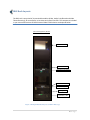
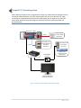
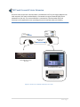
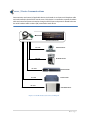
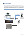
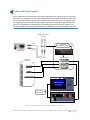
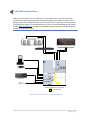
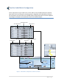
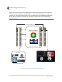
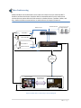
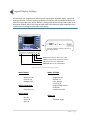
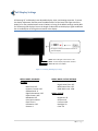
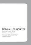
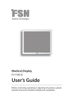
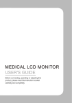
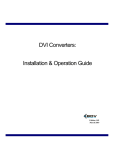
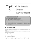
Service Manual: Connection Guide
Integrated Digital Surgical Suite
Prepared by: Matthew Gonsalves
Client: Massachusetts General Hospital – GI
Rev: 1.0 | February 2012
1|Page
Service Manual: Connection Guide
Integrated Digital Surgical Suite
Client: Massachusetts General Hospital
Edition 1.0 | February 2012
The Black Diamond Video logo and IDSS are registered trademarks of Black Diamond Video, Inc.
The information contained herein is subject to change without notice.
All warranties associated with Black Diamond Video products and services are set forth in the
warranty statements accompanying such products and services. Actions taken based upon the
contents of this document should not be construed as constituting an additional warranty. Black
Diamond Video shall not be liable for errors, technical or editorial, contained herein.
For technical support and service, contact Black Diamond Video at:
Black Diamond Video
503 Canal Boulevard
Point Richmond, California, 94804
Phone: (510) 439-4500
Fax: (510) 439-4599
Visit us on the web at: www.blackdiamondvideo.com.
2|Page
Contents
IDSS Rack Layouts ............................................................................................................... 4
Hospital PC Video Integration............................................................................................. 5
Provation PC Integration..................................................................................................... 6
Touch Screen Extension...................................................................................................... 7
Server / Device Communications........................................................................................ 8
OR Camera Integration ....................................................................................................... 9
Picture and Video Capture................................................................................................ 10
Audio Matrix Connections ................................................................................................ 11
ClearOne Audio Matrix Configuration .............................................................................. 12
Windowing Video Sources ................................................................................................ 13
Video Conferencing........................................................................................................... 14
Surgical Display Settings ................................................................................................... 15
Wall Display Settings......................................................................................................... 16
3|Page
IDSS Rack Layouts
The IDSS rack is comprised of 4 customizable modules (Video, Audio, Print/Record and Video
Teleconferencing), all controlled by an intuitive touch-panel interface. The components included
in your customized versions of Black Diamond Video’s IDSS solution are depicted below.
Pedi- Endoscopy Rack / GI Rack
CXPS Video Router
Network Switch
AVCX 3U Control Server
ClearOne Audio Mixer
Sampson Amplifier
Cooling Fans
PowerVar Isolation
Transformer / UPS
Figure 1: Example IDSS Rack Layouts at MGH - Endoscopy
4|Page
Hospital PC Video Integration
Each hospital provided PC that is integrated as an input into a Black Diamond equipped room is
connected as depicted below. The video output signal from each PC is split with one signal
connecting to a designated PC display and the other feeding into an input port on the CXPS
video router. Network and power supply are connected at ports located underneath the
workstation desk.
Partners PC – “PACS”
Power
CAT 5
VGA splitter
Power from PC
into outlet below
workstation
CAT 5 cable into
Partners Network
Jack below
workstation
BDV RGB-DVI
Converter
DVI video from
PC into CXPS
Input Card
Video source
routable to all BDV
destinations
Designated PACS PC
display at workstation
Figure 2: Partners PC Installation & Integration in BDV
5|Page
Provation PC Integration
The Provation PC supplies an input to and receives an output from the CXPS video router. After
a series of signal conversions, the CXPS output enters as the video input to the PC video capture
card and can then be utilized to grab and document images via the Provation software. The
video output from the PC, which includes the video capture card input (Provation software), is
split in two using a VGA splitter. One signal enters into a CXPS input port as a routable video
source and the other is feed directly to the designated PC workstation display.
CXPS Output
Provation Out
DVI Signal Conditioner and
Digital to Analog Converter
BDV RGB-DVI
v
Converter
Designated Provation PC
display at workstation
DVI video from
PC into CXPS
Input Card
RGB Scan Converter
Video into PC
capture card
Provation
Video source
routable to all BDV
destinations
VGA splitter
Provation PC
Figure 3: Provation PC Input / Output Video Integration
6|Page
USB Touch Screen & Printer Extension
All touch screen and printer communication is provided over CAT 5 by the single USB port Icron
2101 extender. Each touch enabled display is connected to a regional extender (REX) that is
powered from the rack. The remote extender is connected to a local extender (LEX) and
terminates at the application server providing the control interface video to the display.
USB
CAT 5
Power
CAT 5
USB over CAT 5
extension
USB
USB
AVCX Application Server
1U or 3U
Touch Display Control Station
HP Laserjet Printer
Figure 4: Touch Screen & Printer Extension via CAT 5
7|Page
Server / Device Communications
Communication and control of applicable devices is achieved via an 8-port serial breakout cable
and card installed in the AVCX 3U control server. Each device is connected to a specific breakout
cable and controlled /communicated to through an RS-232 port and protocols. Noted below are
the serial breakout cable numbers (P#) connected to each device.
RS-232 Serial Breakout
AVCX 3U Control Server
P1: TTY0
P2: TTY1
HD Wall Camera
HD Boom Camera
P3: TTY2
P7: TTY6
ClearOne Audio
Powervar UPS
P8: TTY7
CXPS Video Router
Figure 5: Serial Breakout Cable Connection Diagram
8|Page
OR Camera Integration
Room 1A has a HD boom mounted and HD wall camera available to view, route, and control
from any of the BDV user control stations. The video output feed from each camera is input into
the CXPS router and appears on the user interface as a routable source. Please note that the HD
boom camera video output is RGB and requires conversion to DVI via a BDV RGB-DVI converter.
Camera control is achieved via RS-232 connections from the device to a serial breakout cable on
the AVCX 3U server.
HD Wall Camera
Camera Control Box
Video – HD-SDI Output
Control – RS-232
Video – DVI Output
Control – RS-232
To Rack UPS
(Power)
To Rack UPS
(Power)
Into AVCX Server via Serial Breakout Cable
RGB to DVI
Converter
Into CXPS DVI Input Port
Figure 6: Camera Control / Video Connections
9|Page
Picture and Video Capture
Active video sources can be sent to either the print destination for capturing stills or the record
destination for recordings. The print and record destinations correspond to specific output ports
on the CXPS that feed into capture cards located inside the AVCX 3U server. The capture cards
are programmed specifically for the incoming CXPS output and store the image and video files
on a local 1 Tb hard drive. Capturing stills and recordings can also be remotely trigger via 3.5
mm stereo cables from the trigger enabled device to BDV accessory inputs located on the boom.
Trigger Connections
on Boom
Print
USB GPIO
Image/Record Trigger
Rec.
Input Device
Capture Cards
CXPS DVI
Output Ports
1 TB HDD for
Local Storage
Figure 7: Capturing Stills / Recording Video with Remote Trigger
10 | P a g e
Audio Matrix Connections
Audio inputs and outputs are all connected to a central audio mixer. The mixer comes with
software that enables programming of inputs/output gating as seen below. To access matrix
gating controls click the ClearOne mixer icon in the center of the screen after connecting to and
launching device software. The provided software, Interact, can be downloaded on the product
website www.clearone.com. The diagram below depicts audio connections and channel gating
in Pediatric Endoscopy room 1A
Ceiling Speakers
Into AVCX via Audio Breakout
Provation PC
ClearOne Audio Matrix Configuration
= Channel Gated
Figure 8: Audio Mixer Connections and Gating Diagram
11 | P a g e
ClearOne Audio Matrix Configuration
Further adjustments can be made to the in-room audio via the provided audio mixer software.
Input audio course and fine gains, processing, power, and gating can be adjusted by clicking on
the microphone icon next to the list of available inputs. Output audio levels can also be adjusted
by clicking on the output icon located next to the list of available outputs.
Audio Output Level
Gain Adjustments
Power / Mute Options
Gain Adjustments
Input Options
Power / Mute Options
Audio Input Level
Figure 9: Audio Mixer Configurations via Interact Software
12 | P a g e
Windowing Video Sources
Image processing for multi-source windowing occurs at the output end of the CXPS router. The
constructed windowed image is then feed back into an input of the CXPS where it can then be
routed to any chosen destination (CXPS output). Any alterations of the windowing configuration
will take place immediately and seamlessly, affecting any destination in which windowing is
currently routed to.
Windowing Feedback Loop
Image Processing Based
Upon Windowing Selection
Windowing Output Card
Video Inputs
Quad Windowing
Figure 10: Multisource Windowing Processing and Display
13 | P a g e
Video Conferencing
Audio and video to be conferenced out are input to the AVCX 3U server containing BDV’s
Sapphire conferencing solution. Sapphire-QHD1 is compatible with all major conferencing
systems that can support SIP and H.323 protocols, including Polycom, Tandberg, Codian, and
Sony. Audio and video communications are achieved over the hospital IS network.
Audio to Conf.
Audio from Conf.
Ceiling Speakers
Wired Mics.
Conf. Video Out
Conf. Video In
Audio from Conf.
IS
Network
Sapphire-QHD1
Procedure Room
Bi-Directional
Audio & Video
Far End Conferencing Solution
Conference Room
Figure 11: BDV Video Conferencing Connection Diagram
14 | P a g e
Surgical Display Settings
All Foreseeson 26’’ surgical touch and non-touch displays have adjustable display, input, and
viewing properties. To access the display adjustment interface press the MENU button on the
lower front right side of the display. Below is a listing of the default settings used by BDV for all
Foreseeson displays. Due to the length of video cable to the displays a signal conditioner box is
installed prior to DVI signal termination at the display.
DVI signal conditioner located on the rear of
each surgical display.
Power: When LED light is OFF monitor is ON.
Menu: To access display adjustment interface.
PIP: Must be set to OFF – DVI DIGITAL.
Video Input: Must be set to DVI DIGITAL.
Figure 12: Foreseeson Surgical Display Settings
MENU: ADJUST
Brightness: 50
Contrast: 50
Backlight: 100
MENU: COLOR TEMP
Color Temp: C1
MENU: SETTINGS
Image Size: Full
Gamma: 2.2
Filter: Normal
Over Scan: 0
Image Setting: Preset 1
Zoom/Pan: Freeze Frame: OFF
MENU: IMAGE
MENU: PIP
Red: 50
Green: 50
Blue: 50
PIP Mode: Single
15 | P a g e
Wall Display Settings
All Samsung 55’’ wall displays have adjustable display, input, and viewing properties. To access
the display adjustment interface press the MENU button on the lower front right side of the
display or on the provided remote control. Below is a listing of the default settings used by BDV
for all Samsung wall displays. Due to the length of video cable to the display a signal conditioner
box is installed prior to DVI signal termination at the display.
DVI signal conditioner located on the rear of
each wall display.
Power: When LED light is OFF monitor is ON.
Menu: To access display adjustment interface.
Source: Must be set to HDMI.
Figure 13: Samsung Wall Display Settings
MENU: MODE: ADVANCED
SETTINGS
Black Tone: OFF
Dynamic Contrast: OFF
Shadow Detail: 0
Edge Enhancement: OFF
Expert Pattern: OFF
RGB Mode: OFF
Color Space: Native
Flesh Tone: 0
LED Motion: OFF
Gamma: 0
MENU: MODE: PICTURE OPTIONS
Digital Noise Filter: OFF
MPEG Noise Filter: OFF
HDMI Black Level: LOW
MENU: PICTURE
Brightness: 45
Sharpness: 0
Contrast: 100
Backlight: 20
Color: 50
16 | P a g e