1
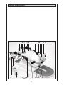
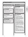
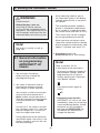
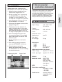
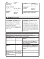
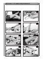
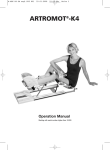
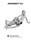
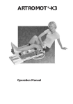
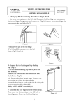
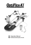
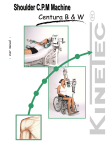
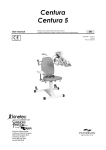
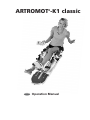
ARTROMOT®-K1 classic
USA/GB
Operation Manual
Device description
1
23 4
5 6
7
7
8 9 10 11 12 13
4
3
2
15
19
7
8
9
3
18 17 16
14
Contents
ARTROMOT®-K1 classic description
3
ARTROMOT®-K1 classic setup illustrations
1.
2.
3.
4.
5.
6.
150
How to use the CPM device
29
1.1
1.2
1.3
1.4
29
29
29
29
Fields of application
Therapy objectives
Indications
Contraindications
ARTROMOT®-K1 classic description
30
2.1
2.2
2.3
2.4
30
31
33
34
Description of the device components
Description of the programming unit
Explanation of symbols
Explanation of symbols (connections and nameplate)
Safety information
35
Device setup
38
4.1 Connecting the device, performance check
4.2 Adjusting the device to the femur length
4.3 Adapting the leg support assemblies/footplate
38
38
39
Setting the treatment values
5.1 General information on programming ARTROMOT®-K1 classic
5.2 Information about the ARTROMOT®-K1 classic therapy parameters
40
40
41
Care, maintenance, transport
42
6.1 Care
6.2 Maintenance (fuse replacement)
6.3 Transport
42
42
43
7.
Environmental Protection Statement
43
8.
Specifications
43
9.
IEC 60601-1-2:2001
44
9.1 Electromagnetic emissions
9.2 Electromagnetic immunity
9.3 Recommended Separation Distances
44
45
47
10. How to reach us
47
11. Technical service
48
11.1 Technical hotline
11.2 Shipment
11.3 Spare parts
48
48
48
12. Declaration of conformity
49
28
1. How to use the CPM device
1.3 Indications
ARTROMOT®-K1 classic is a motoroperated Continuous Passive Motion
(CPM) device used to mobilize knee
and hip joints.
The CPM device is indicated in the treatment of most injuries and diseases of
the knee and hip joints as well as in the
postoperative treatment after knee and
hip joint surgery. Examples:
Suitable for use in hospitals, clinics,
general practices and rental services, it
is an important supplement to medical
and therapeutic treatment.
- joint distortion and contusion
- arthrotomy and arthroscopy procedures
in combination with synovectomy,
arthrolysis or other intra-articular
interventions
1.2 Therapy objectives
- mobilization of joints in anesthetized
patients
CPM therapy with
ARTROMOT®-K1 classic is mainly
used to prevent the negative effects
of immobilization, to allow patients to
regain painless mobility of joints at an
early stage and to promote healing and
achieve a positive functional result.
- operative treatment of fractures,
pseudoarthrosis and osteotomy
- cruciate ligament replacement or
reconstruction
- endoprosthetic implant
Other objectives of therapy include:
1.4 Contraindications
- improvement of joint metabolism
- prevention of joint stiffness
Do NOT use ARTROMOT®-K1 classic
on patients with:
- promotion of the regeneration and
healing of cartilage and damaged
ligaments
- faster hematoma/fluid resorption
- acute inflammatory processes in
the joints, unless on the order of
a physician
- improved lymph and blood circulation
- spastic paralysis
- thrombosis and embolism prophylaxis
- unstable osteosynthesis
29
English
1.1 Fields of application
2. ARTROMOT®-K1 classic description
7. Clamping lever to adjust the height
of the calf support assembly
The motorized CPM device permits
extension and flexion of the knee joint
in the range of -10°/0°/120°,
and of the hip joint in the range of
0°/7°/115°.
8. Calf length fixation screws
(tibia length)
9. Calf length scale (tibia length scale)
It can be used on either side and
requires no configuration change.
10. Strap to secure the foot to the
footplate
These are some of the outstanding
ARTROMOT®-K1 classic features:
11. Footplate
- anatomically correct setup
12. Footplate angle fixation screw
- physiological movements
13. Clamping lever to adjust footplate
rotation and level and to remove the
footplate
- programming unit for precise
adjustment of patient-specific
therapy parameters
14. Connection for programming unit
- symbols for easy operation of the
programming unit
15. Connection for power cord
16. Fuse cap
17. Power switch (ON/OFF)
Biocompatibility
18. Nameplate
The parts of the
ARTROMOT®-K1 classic device that
come in contact with the patient during
the intended use, are designed to fulfill
the biocompatibility requirements of the
applicable standards.
19. Programming unit
2.1 Description of
the device
components
Note: Please fold out page 3!
1. Thigh support assembly
2. Clamping lever to adjust the height
of the thigh support assembly
3. Thigh length scale
(femur length scale)
4. Thigh length fixation screws
(femur length)
5. Knee hinge
6. Calf support assembly
30
2.2 Description of the programming unit
selected angle of
the CPM device
set extension
value
set flexion value
selected direction
of motion
Extension control
Flexion control
Pause control
Speed control
START/STOP key
(during operation:
LED green,
when stopped:
LED yellow)
31
English
2.2.1 Programming unit in normal mode
2.2.2 Programming unit in speed or pause
programming mode
set value of
selected function
(here: speed)
selected function
32
2.3 Explanation of symbols
Symbols that may appear in
the display
Extension
(stretching the knee)
Go to start position
(see Notes in 4.1)
Flexion
(bending the knee)
Controls on
programming unit
locked
(see Notes in 5.1)
Speed
Controls on
programming unit
unlocked
(see Notes in 5.1)
Pause (extension
and flexion)
Service menu
activated, for service
purposes only (also
refer to Service
Manual)
33
English
Symbols on the programming unit:
2.4 Explanation of symbols
(connections and nameplate)
Alternating current
Protective earth
connection
Type B applied part
Power switch OFF
Power switch ON
Refer to accompanying
documents
Do not dispose product
with unsorted household or municipal waste.
34
3. Safety information
Introduction and definitions
Safety information
Read the safety statements before use
of the CPM device. The safety statements are classified as follows:
ARTROMOT®-K1 classic is not
designed for use in areas where
an explosion hazard may occur.
An explosion hazard may result
from the use of flammable anesthetics, skin cleansing agents and
disinfectants.
DANGER!
Indicates an imminent hazard. If
not avoided, this hazard will result
in death or serious injury.
WARNING!
WARNING!
Indicates a hazard. If not avoided,
this hazard can result in death or
serious injury.
Patient hazard –
- Only authorized individuals
are allowed to operate the
ARTROMOT®-K1 classic device.
Individuals are authorized after
receiving training in the operation
of the device and reading this
operation manual.
CAUTION!
Indicates a potential hazard. If
not avoided, this hazard can result
in minor personal injury and/or
product/property damage.
- Before using the device, the
operator must ascertain that it
is in correct working order and
operating condition. In particular,
the cables and connectors must
be checked for signs of damage.
Damaged parts must be replaced
immediately, with original spare
parts.
- Before therapy, a test run
consisting of several exercise
cycles must be completed, first
without and then with the patient.
Check that all fixation screws are
tightened.
- Stop therapy immediately, when
you have doubts about the device
settings and/or the therapy protocol.
35
English
DANGER!
Explosion hazard –
WARNING!
WARNING!
Patient hazard –
Shock hazard –
Strictly observe the following
warnings. Failure to do so endangers
the lives of the patient, the user and
other persons involved.
- It is important that the patient's
position is anatomically correct.
Therefore, carefully verify the
following settings/positions:
1.
2.
3.
4.
- Allow ARTROMOT®-K1 classic
to reach room temperature before
use. If the device has been transported at temperatures below
0 °C/ 30°F), leave it to dry at
room temperature for about 2
hours, until any condensation
has disappeared.
femur length
knee joint axis
tibia length and leg rotation
leg support assemblies
- Movements must not cause pain
or irritation.
- Patients must be fully conscious
while being instructed in the use
of the CPM device and during
therapy.
- The ARTROMOT®-K1 classic
device must only be operated
in dry rooms.
- When disconnecting the device
from the power line, remove the
plug from the wall outlet first,
before disconnecting the cable
from the device.
- Only the responsible physician
or therapist is able and allowed
to choose the therapy parameters
to use. It is the physician's or
therapist's decision whether or
not to use the CPM device on
a specific patient.
- When connecting the device to
other equipment or when creating
a medical system, check that the
sum of leakage currents will not
cause any hazard. Please contact
ORMED, if you have questions in
this matter.
- The patient must be familiar
with the functions of the
ARTROMOT®-K1 classic
programming unit and the unit
must be within easy reach of the
patient, allowing him or her to
stop therapy, if needed. Patients
unable to operate the programming unit, e.g. paralytic patients,
must never be left unattended
during therapy.
- Do not use multiple portable
socket outlets (MPSO) to connect
the device to the power line.
ARTROMOT®-K1 classic must be
connected to a properly installed
wall outlet with a non-fused
earthed wire. Before connecting
the power cord, it must be completely unrolled and placed such
that it will not get caught by the
moving parts of the device.
- Any accessories used with
ARTROMOT®-K1 classic must
first be approved by ORMED.
- Do not allow parts of the body
or objects (such as blankets,
cushions, or cables) to get caught
in the moving parts of the CPM
device.
- Before cleaning and service interventions, disconnect the device
from the power line by removing
the power cord from the wall
outlet.
- Liquids must not be allowed
to enter the CPM device or the
programming unit. If liquids have
entered into the devices,
ARTROMOT®-K1 classic must be
immediately checked by a service
technician, before it can be reused.
36
CAUTION!
Equipment damage –
- Magnetic and electrical fields are
capable of interfering with the
proper performance of the device.
For this reason make sure that all
external devices operated in the
vicinity of the CPM device comply
with the relevant EMC requirements. X-ray equipment, MRI
devices and radio systems are
possible sources of interference
as they may emit higher levels of
electromagnetic radiation. Keep
the CPM device away from these
devices and verify its performance
before use.
- Check that the voltage and
frequency ratings of your local
power line are those indicated
on the nameplate.
- The leg support element withstands a maximum continuous
load of 20 kg.
- Do not allow any objects (such
as blankets, cushions, or cables)
to get caught in the moving parts
of the CPM device.
- Do not expose the
ARTROMOT®-K1 classic device to
direct sunlight, because some
of the components may reach
inadmissibly high temperatures.
- Refer repair and maintenance to
authorized persons.
- Route all cables below the device
frame to either side, ensuring
that they cannot get caught by
the moving parts during operation.
- Inspect ARTROMOT®-K1 classic
for damage and loose connections
at least once a year. Damaged
and worn parts must immediately
be replaced with original spare
parts by authorized staff.
CAUTION!
Preventing chafing and pressure
sores –
When your patient is adipose,
very tall or very short, be sure
to prevent chafing and pressure
sores. Place the leg concerned in
a moderate abduction position, if
deemed appropriate.
37
English
WARNING!
Equipment malfunction –
4. Device setup
ARTROMOT®-K1 classic enters the
home position (for home position
values, refer to section 4.1), the device
has passed the performance check.
Note: For a better understanding
of each step, please fold out pages
3 and 150.
4.1 Connecting the
device, performance
check
The device also runs performance
checks regularly during operation. This
is what happens, if a problem is identified:
- An audio signal sounds.
- The device switches off immediately.
- The message “ERROR”, accompanied
by a code number (e.g. ERROR 5),
appears on the display.
1. Connect the power cord to socket
(15) of the device and mains plug to
a wall outlet with a non-fused earthed
wire (100 to 240 Volt, 50/60 Hz).
In this situation, you may attempt to
restart the device by turning the device
briefly off and on again with the power
switch. If the error message persists,
have the device inspected by a Service
technician, before using it again.
2. Turn the power switch (17) on.
3. Follow these steps to set the carriage
to the home position.
Press the Extension key
4.2 Adjusting the device
to the femur length
and, holding it depressed, rotate
until 30° appears in the display
above the control.
1. Measure the length of the patient's
thigh (femur) from the greater
trochanter to the lateral knee joint
cavity (Fig. A).
In the same manner, select a
Flexion value of 35°.
2. Set the carriage to the home position
(see 4.1).
Then press the START/STOP key.
3. Set the measured value at the
femur scale (3) of the carriage.
When the carriage has reached this
range and does not stop automatically, press the START/STOP key
again to stop any movement.
- Loosen the two fixation screws (4).
- Extend the scale (3) to the required
length.
Note!
- Tighten the fixation screws (4) to
set the scale to the new length.
ARTROMOT®-K1 classic will stop
automatically in the home position
range, only if it was positioned
outside this range (30° to 35°) at
the time of programming (also
refer to 5.2)
CAUTION!
Equipment damage –
Do not attempt to extend the
femur scale beyond the stop.
Performance check
If the programming unit can be
operated as described above and
38
4.3 Adapting the leg
support assemblies/footplate
CAUTION!
Equipment damage –
1. Set the leg support assemblies and
the footplate (1, 6, 11) to the expected
positions before accommodating the
patient.
- Loosen fixation screws (8) to adjust
the footplate (11) to the length of the
patient's lower leg (Fig. C).
CAUTION!
Patient hazard –
Loosen clamping lever (13) and
adapt the footplate's rotation and
height to the patient (Fig. D).
Ensure that the rotational axes of
the CPM device and of the knee
joint coincide both in the vertical
and in the horizontal plane (Fig. G).
Loosen fixation screw (12) and adapt
the angle to the patient's foot (turn
the screw a few revolutions until the
footplate can be easily adjusted).
Symbol 1:
Measurement of the
patient's femur length
from the greater
trochanter to the
knee joint cavity
For short patients you can reverse
the footplate's bracket 180° (Fig. H)
to adapt the footplate to shorter
calves:
• Loosen clamping lever (13) and
remove the footplate (11).
Symbol 2:
Set the carriage to
the home position
(see 4.1) and adjust
it to the measured
femur length.
• Loosen the fixation screws (12).
• Reverse the bracket 180°.
• Screw the footplate to the bracket
and tighten the clamping lever.
Note!
Symbol 3:
Adjust height of calf
and thigh support
assemblies. Adjust
the footplate to the
height and length of
the lower leg.
When reversing the footplate,
ensure that the pins below the
clamping lever engage with the
recesses in the bracket.
- To adjust the height of the support
assemblies for calf (1) and thigh
(6), loosen clamping levers (2) and (7)
(Figs. E/F).
2. Place the patient’s leg on the carriage and repeat the steps outlined
under 1 above to adjust the device
to the patient.
39
English
Cover the leg support assemblies
with disposable tissues when
using ARTROMOT®-K1 classic
immediately after surgery.
This helps prevent discoloration.
5. Setting the treatment values
When adjusting speed or pause,
the information shown in the display
changes automatically as you press
the control.
WARNING!
Patient hazard –
Before therapy, a test run
consisting of several exercise
cycles must be completed without
the patient. Then repeat the test run
with the patient and check that the
movement does not cause any pain.
The selected parameter (speed or
pause) is immediately represented
by its symbol in a large format plus
the current value (also refer to 2.2.2).
The current value can be changed
by turning the depressed control.
When you have set the new value,
release the control and the standard
display reappears automatically after
approx. 5 seconds (see also 2.2.1).
Note!
See also 2.2 and 2.3 as well as
page 150!
3. Subsequently press the
START/STOP key to start therapy.
5.1 General information
on programming
ARTROMOT®-K1
classic
Note!
Refer to sections 5.2 for
a description of the parameters.
- To prevent accidental changes of
the parameter settings, lock the
programming unit by simultaneously pressing the "Extension"
and "Speed" controls.
1. You activate a function by
briefly pressing a control on
the programming unit.
2. You select a treatment value by
pressing the respective control
and turning it in either direction.
Press both controls again to
unlock.
You increase a value by turning the
control clockwise towards the +
(plus) symbol and you decrease a
value by turning the control counterclockwise towards the - (minus)
symbol.
- Emergency stop function:
ARTROMOT®-K1 classic will stop
immediately, when any of the keys
is pressed during therapy. Patient
treatment can be resumed by
pressing the START/STOP key.
The device will automatically
change the direction.
For the first 5° the values in the display change in steps of 1°, then the
interval changes to 5° so that you
reach the target value faster.
During adjustment of the extension
and flexion angles, the values in the
display change as you turn the control after pressing it.
40
Note!
- If the carriage is positioned
within the programmed range
of motion at the time therapy
begins, the therapy session will
start immediately.
The programmed value and the
value measured at the patient's
knee may deviate slightly.
If the carriage is positioned
outside the programmed range
of motion at the time therapy
starts, it will first enter the position
“extension +10°”. The carriage
will stop in this position and you
can initiate the therapy session
by pressing the START/STOP
key again.
The speed can be adjusted between
5 % and 100 % in steps of 5 %.
Default setting: 50 %
■ Pauses
Pauses occur at the selected limits
where stretching turns into bending
and bending into stretching (selected
extension and flexion values).
The value entered applies to both
extension and flexion pause.
5.2 Information about
the ARTROMOT®-K1
classic therapy
parameters
Pauses can be set to any value between 0 and 59 seconds in steps of 1
second, and to values between 1
and 59 minutes in steps of 1 minute.
When selecting the seconds, the
value changes in 1-second steps for
the first five seconds. Subsequently
the interval changes to 5-second
steps.
- You select a function by pressing the
corresponding control
- You change the treatment values by
turning the depressed control.
- You initiate the treatment session by
pressing the START/STOP key
The minutes are always adjusted in
1-minute steps.
Default setting: no pause
■ Extension (streching)
- Maximum knee extension:
-10 degrees
- Maximum hip extension:
7 degrees
■ Flexion (bending)
- Maximum knee flexion:
120 degrees
- Maximum hip flexion:
115 degrees
41
English
■ Speed
6. Care, maintenance, transport
6.1 Care
6.2 Maintenance
(fuse replacement)
WARNING!
Shock hazard –
Check before each use
Unplug the device from the power
line before cleaning.
Visually inspect the device for signs of
mechanical damage before each use.
Shock hazard, equipment damage –
Liquids must not enter the device
or the programming unit.
If you detect damage or malfunctions
that may impair the safety of the patient
or of the operator, have the device
repaired before using it.
- ARTROMOT®-K1 classic can be
disinfected by wiping down with a
disinfectant. Thus, it complies with the
special hygiene standards for medical
technical equipment.
Technical Inspections
For safety, the devices require regular
maintenance. To maintain the functional
and operational safety, check all
components for damage and loose
connections at least once a year.
- The enclosure and removable leg
support assemblies can be cleaned
with commonly used disinfectants
and mild household detergents.
These checks should be performed by
persons with adequate training and
experience. Damaged and worn parts
must immediately be replaced with
original spare parts by authorized staff.
- Use only a damp cloth to wipe
the carriage down.
Clean the sheath of the programming
unit on a regular basis. Remove it
from the programming unit before
cleaning. Allow the sheath to dry
before inserting the programming
unit again.
The checks can be carried out by
ORMED within the framework of a
service agreement.
Contact ORMED for details.
The device does not require additional
regular maintenance.
CAUTION!
Fuse replacement
Equipment damage –
- The plastic material used is not
resistant to mineral acids, formic
acid, phenols, cresols, oxidizing
agents and strong organic or
inorganic acids with a pH value
below 4.
WARNING!
Patient hazard, equipment
malfunction and damage –
The replacement of fuses must
be referred to specialists as defined
in IEC 60364 or similar standards
(e.g. biomedical technicians,
electricians, electronics installers).
- Use only clear disinfectants
to prevent discoloration of the
device.
- Do not expose the CPM device
to strong ultraviolet radiation
(sunlight) and fire.
Fuses used must be T1A fuses.
42
6.3 Transport
7. Environmental
protection statement
The product described in this operation
manual must not be dispose of with
unsorted household or municipal waste.
It requires separate disposal. Please
contact ORMED for information about
the possible recycling of the product.
1. Adjust the femur length to 49 cm
and the tibia length to 45 cm.
2. Set the carriage to 0° by pressing
the START/STOP key when the
carriage is in the 0° position. This
will stop the carriage in that position
3. Push the power switch to turn off
the ARTROMOT®-K1 classic.
8. Specifications
4. Disconnect the power cord and the
programming unit.
Input ratings:
5. The device must be stored in its
original shipping box for transport.
ORMED GmbH & Co. KG cannot be
held liable for damage in transit, if
the original shipping box was not used.
6. Inser the programming unit into
the space provided in the molded
polystyrene pads and secure with
adhesive tape.
7. Set the footplate to a horizontal
position.
9. Place the power cord at the
bottom of the box before inserting
the ARTROMOT®-K1 classic including
the polystyrene pads.
Programming Unit
Current
consumption:
850 – 370 mA
Fuses:
2 x T1A
Protection class:
I
Applied part:
type B
Max. load
on carriage:
20 kg
Dimensions
length:
width:
height:
8. Now slide the polystyrene pads
onto the ARTROMOT®-K1classic.
100 – 240 V AC/
50 – 60 Hz
96 cm
35 cm
min. 23 cm to
max. 56 cm
Adjustment ranges (min./max.):
Femur range:
approx. 31 – 49 cm
Power Cord
Lower leg range:
approx. 25 – 57 cm
Weight:
11 kg
Materials used:
ABS, POM
(Delrin 100),
PUR, PA, FR4,
aluminium, stainless
steel, brass
MDD
class 2a
Standards compliance:
IEC 60601-1:1988
+ A1:1991
+ A2:1995
Certification:
43
ANSI/UL 60601-1
CAN/CSA C22.2
No. 601.1
English
Follow these steps to prepare the
ARTROMOT®-K1 classic for transport:
EMC
(electromagnetic
compatibility)
IEC 60601-1
2:2001
Ambient conditions (operation)
temperature:
+10 ºC to +40 ºC
(50 °F to +104 °F)
Ambient conditions
(storage, transport)
temperature:
-24 ºC to +60 ºC
(-12 °F to +140 °F)
relative humidity:
atmospheric
pressure:
relative humidity:
atmospheric
pressure:
30 % to 75%
700 hPa to
1060 hPa
20 % to 85 %
Subject to change without notice.
(08/06)
700 hPa to
1060 hPa
9. IEC 60601-1-2:2001
The ARTROMOT®-K1 classic device is
subject to particular precautions regarding electromagnetic compatibility
(EMC). The device must be installed and
put into service strictly in compliance
with the EMC directives put forth in the
accompanying documents.
ARTROMOT®-K1 classic should not
be used adjacent to or stacked with
other equipment.
If adjacent or stacked use is necessary,
ARTROMOT®-K1 classic should be
observed to verify normal operation in
the configuration in which it will be used.
Portable and mobile RF communication
systems may affect the ARTROMOT®-K1
classic device.
We can guarantee the specified electromagnetic emission and immunity data
only if the manufacturer's original spare
parts are used in repair and maintenance
of the device.
9.1 Electromagnetic emissions
Guidance and Manufacturer’s Declaration – Electromagnetic Emissions
ARTROMOT®-K1 classic is intended for use in the electromagnetic environment
specified below. It is the responsibility of the customer or user to ensure that the
ARTROMOT®-K1 classic device is used in such an environment.
Emissions test
Compliance
Electromagnetic environment –
guidance
RF emissions to
CISPR 11
Group 1
ARTROMOT®-K1 classic uses RF energy
only for its internal function. Therefore, its
RF emissions are very low and are not
likely to cause any interference in nearby
electronic equipment.
RF emissions to
CISPR 11
Class B
ARTROMOT®-K1 classic is suitable for
use in all establishments, including domestic
and those directly connected to the public
low-voltage power supply network that
supplies buildings used for domestic
purposes.
Harmonic emissions to
IEC 61000-3-2
not applicable
Voltage
fluctuations/flicker emissions to IEC 61000-3-3
not applicable
44
9.2 Electromagnetic immunity
Guidance and Manufacturer’s Declaration – Electromagnetic Immunity
Electrostatic
discharge (ESD)
to IEC 61000-4-2
± 6 kV contact
e 6 kV contact
e 6 kV contact
e 8 kV air
e 8 kV air
Electrical fast transi- e 2 kV for power
ent/burst to IEC
supply lines
61000-4-5 ± 2 kV for
power supply lines
e 1 kV for
input/output lines
Surges to IEC
61000-4-5
Voltage dips, short
interruptions and
voltage variations
on power supply
input lines to IEC
61000-4-11
Mains power should be
that of a typical commercial
or hospital environment.
e 1 kV for input/out-
put lines
e 1 kV differential
mode
e 1 kV differential
e 2 kV common
mode
e 2 kV common
mode
mode
Mains power should be
that of a typical commercial
or hospital environment.
< 5 % UT
(> 95 % dip in UT)
for 5 s
Mains power should be
that of a typical commercial
or hospital environment.
If the user of the
40 % UT
ARTROMOT®-K1 classic
(60 % dip in UT) for device requires continued
5 cycle
operation during power
mains interruptions, it is
70 % UT
recommended that the
(30 % dip in UT) for ARTROMOT®-K1 classic
25 cycles
device be powered from an
uninterruptible power supp< 5 % UT
ly or a battery.
(> 95 % dip in UT)
for 5 s
3 A/m
3 A/m
< 5 % UT
< 5 % UT
(> 95 % dip in UT ) (> 95 % dip in UT )
for ) cycle
for ) cycle
40 % UT
(60 % dip in UT)
for 5 cycle
70 % UT
(30 % dip in UT)
for 25 cycles
Power frequency
(50/60 Hz) magnetic
field to IEC 610004-8
e 2 kV for power
supply lines
Floors should be wood,
concrete or ceramic tile.
If floors are covered with
synthetic material, the
relative humidity should
be at least 30%.
Power frequency magnetic
fields should be at levels
characteristics of a typical
location in a typical
commercial or hospital
environment. Portable and
mobile RF communications
equipment are used no
closer to any part of the
ARTROMOT®-K1 classic
device, including cables,
than the recommended
separation distance calculated from the equation applicable to the frequency of
the transmitter.
NOTE: UT is the a.c. mains voltage prior to application of the test level.
45
English
ARTROMOT®-K1 classic is intended for use in the electromagnetic environment specified
below. It is the responsibility of the customer or user to ensure that the ARTROMOT®-K1
classic device is used in such an environment.
IEC 60601-test
Compliance level Electromagnetic
Immunity test
level
environment - guidance
Guidance and Manufacturer’s Declaration – Electromagnetic Immunity
ARTROMOT®-K1 classic is intended for use in the electromagnetic environment specified
below. It is the responsibility of the customer or user to ensure that the ARTROMOT®-K1
classic device is used in such an environment.
Immunity test
IEC 60601
test level
Compliance level
Electromagnetic environment-guidance
Recommended separation
distance:
Conducted RF to
IEC 61000-4-6
3 Vrms
150 kHz to
80 MHz
3 Vrms
Radiated RF to
IEC 61000-4-3
3 V/m
80 MHz to
2.5 GHz
3 V/m
d =
r
1.2 öP
d = 1.2
800 MHz
r
öP
d = 2.3
2.5 GHz
80 MHz to
r
öP
800 MHz to
where P is the maximum output
power rating of the transmitter
in watts (W) according to the
transmitter manufacturer andd
is the recommended separation
distance in meters (m).
Field strengths from fixed RF
transmitters, as determined by
an electromagnetic site survey a,
is less than the compliance
level in each frequency rangeb.
Interference may occur in the
vicinity of equipment marked
with the following symbol
NOTE 1: At 80 MHz and 800 MHz, the higher frequency range applies.
NOTE 2: These guidelines may not apply in all situations. Electromagnetic propagation
is affected by absorption and reflection from structures, objects, and people.
a) Field strengths from fixed transmitters, such as base stations for radio (cellular/cordless)
telephones and land mobile radio, AM and FM radio broadcast and TV broadcast cannot
be predicted theoretically with accuracy. To assess the electromagnetic environment due
to fixed RF transmitters, an electromagnetic site survey should be considered. If the measured field strength in the location in which the ARTROMOT®-K1 classic device is used
exceeds the applicable RF compliance level above, the ARTROMOT®-K1 classic device
should be observed to verify normal operation. If abnormal performance is observed,
additional measures may be necessary, such as reorienting or relocating the
ARTROMOT®-K1 classic device.
b) Over the frequency range 150 kHz to 80 MHz, field strengths should be less than 3 V/m.
46
9.3 Recommended separation distances between portable and mobile RF
communications equipment and the ARTROMOT®-K1 classic device.
The ARTROMOT®-K1 classic is intended for use in an electromagnetic environment
in which radiated RF disturbances are controlled. The customer or the user of the
ARTROMOT®-K1 classic device can help prevent electromagnetic interferences by
maintaining a minimum distance between portable and mobile RF communications equipment (transmitters) and the ARTROMOT®-K1 classic device as recommended below,
according to the maximum output power of the communications equipment.
separation distance according to frequency of transmitter
m
150 kHz to 80 MHz
d =
r
1.2 öP
80 MHz to 800 MHz
d =
r
1.2 öP
800 MHz to 2,5 GHz
d =
r
2.3 öP
0.01
0.12
0.12
0.23
0.1
0.38
0.38
0.73
1
1.2
1.2
2.3
10
3.8
3.8
7.3
100
12
12
23
For transmitters rated at a maximum output power not listed above, the recommended
separation distance d in meters (m) can be estimated using the equation applicable to the
frequency of the transmitter, where P is the maximum output power rating of the transmitter
in watts (W) according to the transmitter manufacturer.
NOTE 1: For calculation of the recommended separation distance of transmitters in the
frequency range from 80 MHz to 2.5 GHz an additional factor of 10/3 was taken into
account to reduce the probability of mobile/portable communications equipment brought
into the patient environment by accident causing any malfunction.
NOTE 2: These guidelines may not apply in all situations. Electromagnetic propagation
is affected by absorption and reflection from structures, objects, and people.
10. How to reach us
We would be happy to answer any
questions you may have about our
products or services.
Warranty:
2 years (mechanical parts)
2 years (electronics)
■ ORMED international
Please contact your local dealer or
the ORMED headquarters in Germany.
Sales:
ORMED GmbH & Co. KG
Merzhauser Straße 112
D-79100 Freiburg
■ Headquarters Germany
ORMED GmbH & Co. KG
Merzhauser Straße 112
79100 Freiburg - Germany
Tel. +49 761 45 66-01
Fax +49 761 45 66 55-01
■ Internet
www.ormed.de
e-mail: [email protected]
47
English
rated maximum output
power of transmitter
W
11. Technical service
11.1 Technical hotline
Do you have any technical questions?
Do you need technical service?
Telephone: +49-180-5-1 ormed de
+49-180-5-1-67 63 33
Fax:
+49-180-5-3 ormed de
+49-180-5-3-67 63 33
11.2 Shipment
To prevent damage during transport,
only use the original shipping box.
These boxes can be obtained from
ORMED.
Before packing the CPM device, set it to
the transport position (see chapter 6.3).
11.3 Spare parts
Refer to the Service Manual for
the most recent list of spare parts.
When ordering spare parts, always
specify:
- item
- description
- part number
- quantity
- serial number of the CPM device
Note!
Refer repairs to authorized,
specially trained staff.
ORMED GmbH & Co. KG offers
service training for your personnel.
Surcharges may apply in certain cases
to spare parts ordered in low quantities.
48
In compliance with the Council Directive 93/42/EEC of 14 June 1993
concerning medical devices, the company
ORMED GmbH & Co. KG
Merzhauser Straße 112
D-79100 Freiburg
declares that the products of the product line
ARTROMOT® (see Annex)
fulfill the requirements of the Council Directive 93/42/EEC of 14 June 1993,
Annex II as well as the essential requirements of Annex I.
0297
Freiburg, August 28th, 2006
- QA Management Representative-
Annex:
ARTROMOT®-S2 PRO
ARTROMOT®-S3
ARTROMOT®-S3 Comfort
ARTROMOT®-K1
ARTROMOT®-K2
ARTROMOT®-K2 PRO
ARTROMOT®-K2 PRO Chip
ARTROMOT®-K3
ARTROMOT®-K4
ARTROMOT®-SP2
ARTROMOT®-E2
ARTROMOT®-E2 compact
49
English
C ONFORMITIY
OF
D ECLARATION
Declaration of conformity
ARTROMOT®-K1 classic setup illustrations
A
B
C
D
E
F
G
H
150
© ORMED 806
O R M E D G m b H & C o . K G • M e r z h a u s e r S t r a ß e 112 • D - 7 910 0 F r e i b u r g
Te l + 4 9 7 6 1 4 5 6 6 - 0 1 • F a x + 4 9 7 6 1 4 5 6 6 - 5 5 0 1 • w w w. o r m e d . d e
E-Mail: info @ ormed.de
DIN EN 13485
ORMED Nr. 018 829-01