1
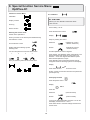
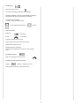
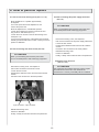
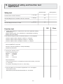
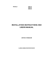
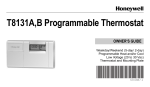
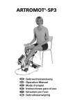
OptiFlex-K1
Service Manual
Table of contents
2. Purpose
1. History
2
2. Purpose
2
3. General
2
4. Packing and unpacking OptiFlex-K1
5
5. Block diagram of the electronic parts OptiFlex-K1
6
6. Bill of material for service parts OptiFlex -K1
7
7. Figure for bill of material
8
The purpose of this Service Manual is to help you make
simple repairs on the OptiFlex -K1. Only authorized staff may
perform repairs and maintenance as the manufacturer’s
warranty and liability would otherwise be invalidated.
Only original parts may be used for servicing in accordance
with the attached spare parts list.
3. General
3.1 Electronics, connection cables
8. Special function Service menu for OptiFlex-K1
10
9. How to perform repairs
12
10. Checklist of safety and function test OptiFlex-K1
13
No plugs may be connected or disconnected while the
unit is switched on. Always switch the OptiFlex -K1
off before connecting or disconnecting a plug.
The locks for spiral cable for the hand-held programming unit have to be closed at all times.
When you assembling with electronic parts make sure
to use ESD (Electro Static Discharge) equipment.
If you have to exchange any of the printed circuit boards
including the knee electronics or motor control you have
to perform a calibration.
Possible errors: Errors will be displayed on the handheld programming unit as follows shown:
1. History
Revision
Date
Name
Change
1
01.08.2007
S. Herr
Service Manual
created
ERROR
XX
(XX = Number of the error)
1
Potentiometer error:
Wrong angle information
-> Check the femur settings
-> Replace knee electronics (Pos. 3)
-> Replace motor control (Pos. 20)
2
Failure at the potentiometer:
Connection to the potentiometer is interrupted
-> Replace the spiral cable of the potentiometer (Pos. 19)
-> Replace knee electronics (Pos. 3)
-> Replace motor control (Pos. 20)
2
3
Motor driver error:
The motor driver IC reported an error
-> Replace motor control (Pos. 20)
4
Motor error:
The motor did not turn properly
-> Replace motor control (Pos. 20)
-> Replace the motor (Pos. 21)
21 Range exceeded:
The measured angle is out of the range of motion
-> Replace motor control (Pos. 20)
5 Motor over current:
The current for the motor exceeded the maximum limit
-> Check the mechanics (Pos. 25)
-> Replace motor control (Pos. 20)
-> Replace the motor (Pos. 21)
22 ROM error in the hand held programming unit:
Memory error in the hand held programming unit
-> Replace the hand held programming unit (Pos. 14)
6 Motor control error:
Internal error in the motor control.
-> Replace motor control (Pos. 20)
23 Invalid parameter:
Internal error in the hand held programming unit
-> Replace the hand held programming unit (Pos. 14)
7 Eprom access error:
Memory error in the access of the EPROM
-> Replace the hand held programming unit (Pos. 14)
24 24V supply error motor control:
Error in the 24V supply in the motor control
-> Replace motor control (Pos. 20)
-> Replace the power supply electronics (Pos. 23)
8 CPM ROM error:
Memory error in the motor control
-> Replace motor control (Pos. 20)
25 Bus error:
Bus system error
-> Replace the spiral cable of the hand held
programming unit (Pos. 15)
-> Replace the hand held programming unit (Pos. 14)
-> Replace motor control (Pos. 20)
9 Communication:
Communication to the motor control is not possible
-> Check spiral cable and connector (Pos. 15)
-> Replace the hand held programming unit (Pos. 14)
-> Replace motor control (Pos. 20)
26 24V supply hand held programming unit:
24V supply of the hand held programming unit is
defective
-> Replace the hand held programming unit (Pos. 14)
10 General error in the motor control:
Unknown error in the motor control
-> Replace motor control (Pos. 20)
11 Motor enable timeout
Motor could not be enabled in time
-> Replace motor control (Pos. 20)
27 5V supply hand held programming unit:
5V supply of the hand held programming unit is defective
-> Replace the hand held programming unit (Pos. 14)
28 3.3V supply hand held programming unit:
3.3V supply of the hand held programming unit is
defective
-> Replace the hand held programming unit (Pos. 14)
12 Invalid parameter motor error:
Motor has received a invalid parameter
-> Replace motor control (Pos. 20)
-> Replace the hand held programming unit (Pos. 14)
29 Calibration:
The calibration data in the motor control are wrong.
-> Perform a calibration (see chapter 8.1)
13 Stop release error:
The motor could not be released
-> Replace motor control (Pos. 20)
-> Replace the hand held programming unit (Pos. 14)
30 Calibration error:
-> Repeat the calibration (see chapter 8.1)
-> Replace knee electronics (Pos. 3)
-> Replace motor control (Pos. 20)
14 Unexpected motor Stop:
-> Check spiral cable and connector (Pos. 15)
-> Replace motor control (Pos. 20)
31 Calibration timeout:
-> Replace motor control (Pos. 20)
15 Motor disabled:
Motor control disabled the motor.
-> Replace motor control (Pos. 20)
32 Motor enable error:
The motor could not be enabled
-> Replace motor control (Pos. 20)
16 Wrong command in the motor :
-> Replace motor control (Pos. 20)
-> Replace the hand held programming unit (Pos. 14)
33 Motor disable error:
The motor could not be disabled
-> Replace motor control (Pos. 20)
17 5V supply error:
5V supply of motor control not sufficient
34 Motor stop error:
Motor stop command timeout error
-> Replace motor control (Pos. 20)
-> Replace motor control (Pos. 20)
18 Initialise error real time clock:
-> Replace the hand held programming unit (Pos. 14)
35 Configuration error:
Invalid configuration of the hand held programming unit
-> Replace the hand held programming unit (Pos. 14)
19 Communication error real time clock:
-> Replace the hand held programming unit (Pos. 14)
20 Error real time clock:
-> Replace the hand held programming unit (Pos. 14)
3
45 Wrong product combination:
Mixup between non compatible device and hand held
programming unit
-> Use the correct hand held programming unit (Pos. 14)
46 Handset error internal communication:
Invalid interchip communication inside the hand held
programming unit
-> Replace the hand held programming unit (Pos. 14)
47 Internal communication error motor control:
Internal communication error motor control.
-> Replace motor control (Pos. 20)
48 User stoped the special function
49 Unknown error in the motor control:
-> Replace motor control (Pos. 20)
3.2 Mechanics
The movable screws should not be completely unscrewed when adjustments are being made. Make sure
that the movable screws are tightened for operation
and transport.
The frame is unstable:
Possible cause: Bolt / screws missing or loose. Tighten
the screws / bolts.
3.3 Others
Do not clean the housing or the support with grease or
oil.
No solvents may be used when cleaning the
OptiFlex-K1.
4
4. Packing and unpacking the OptiFlex-K1
The following settings must be made to transport the
OptiFlex-K1:
Move the two styrofoam parts and the extra
protection for the knee joint on the device
First put the power cord and the extra box with the hand
held programming unit on the bottom of the box as shown
on the figure below and then the OptiFlex-K1 with the two
styrofoam parts.
Set the packing setting in the menu or move the device
in a position of EXTENSION 0 degrees.
Switch off the OptiFlex-K1.
Remove the power cord and disconnect the hand
held programming unit.
Only use original packaging for transport.
Put the hand-held programming unit into the extra box.
Set the femur lenght on maximum and the lower leg
setting on 42 cm.
Set the angle joint horizontal.
Extra box with the hand-held
programming unit
5
Extra protection for
the knee joint
5. Block diagramm of the electronic parts OptiFlex-K1
Hand-held programming unit
Display
Motor Control
Controllogic
Microprocessor
5
Control-logic
24 V
Ground
Memory
Clock
Stop
Microprocessor
Motor
driver
Motor
Pot.
Control
Pot.
2
Keypad
Power supply 24 V DV
6
6. Bill of material for service parts OptiFlex-K1
Position
Description
Ordernumber
2
Fixation screw
GN534-32-M5sw
Washer
DIN125D6A2
Countersunk screw
DIN933M5x20A2
3
Knee electronics complete
0.0037.041
4
Fixation screw
GN534-32-M5sw
Washer
DIN125D6A2
Countersunk screw
DIN933M5x20A2
Distance disk
DIN988D6x12x0,3
Footplate
0.0037.045
6
7
Fixation screw
GN534-40-M6sw
Rubber puffer complete for angle joint
0.0037.202
9
Connection hand held programming unit
2.0037.004
10 + 12
Power switch (ON/OFF) with connection
0.0034.245
11
Fuses cap
0.0034.246
Fuses 1 AT
0.0000.005
Hand held programming unit with spiral cable OptiFlex
0.0037.062
Protection for hand held programming unit
0.0037.103
Holder K1 hand held programming unit
0.0037.076
15
Spiral cable hand held programming unit
2.0037.035
16
Holding clip
0.0031.004
17
Housing cover OptiFlex-K1 with sticker
0.0037.205
18
Housing cover OptiFlex-K small
0.0037.206
19
Spiral cable black for potentiometer
0.0037.007
20
Motor control K1
2.0037.901RevB
21
Motor complete
0.0037.075
22
Wire set
2.0037.005
23
Power supply electronics
0.0034.244
24
Lip
2.0037.105
Wire for lip
0.0031.300
Spindle complete K1 with alu profile
0.0037.210
Power cord USA version
0.0034.011
Option: Frame adapter add-on-kit
0.0037.204
14
25
7
7. Figure for bill of material
7 6
4
2
3
18
19
15
16
17
24
10/11/12
9
10/11/12
9
14
20
21
23
8
22
Position 25
9
8. Special function Service Menu
OptiFlex-K1
Function of service Menu
8.1 Calibration
Calibration
ATTENTION!
Display contrast
Before you do a calibration switch the device
OFF and ON.
Error log
Femur setting: 49 cm.
Device runtime
Press the Extension control.
Entering the service menu:
Switch off the OptiFlexK1.
Display:
When you switch on the device press simultaneously
Keep on pressing the control
the Extension control
Extension
(OptiFlex-K1 move in
direction Extension)
Display will show following symbol:
Entering code.
Flexion
(OptiFlex-K1 move in
direction Flexion)
For the code press the control as shown below:
until the OptiFlex-K1 reach 0 degrees.
and the Flexion control
1
3
2
4
Press START, the calibration starts automatically. The
device will reach both maximum points and move
between –10 bis 120 degrees with different speed.
Wait until the OptiFlex-K1 stops.
If the calibration was succesful the device stops at
0 degrees and show following symbols on the display:
Now you see the symbols of the service menu:
Display:
Press STOP twice to leave the service menu.
Finally, a safety and function test has to be performed
(see chapter 10).
8.2 Display contrast
Press the speed control.
Display:
XX %
Press the control
Extension
(value decrease)
Flexion
(value increase)
to set up the requested display contrast. You can set
the display contrast from 0 – 100 %
Press STOP twice to save the settings and leave the
service menu.
10
8.3 Error log
Press the pause control
You will find following information on the display:
Upper line: Number of the current showed error message
and the total number of the saved error messages.
Lower line: Error message
Left side: The symbol of the causer.
= Hand held programming unit
= Motor
Press the control
Extension
(last entry)
Flexion
(next entry)
to see the entries of the error log.
Press STOP twice to leave the service menu.
General note to the error log
Entries are always in english.
The entries are ordered by causer and not in temporal
order.
8.4 Device runtime
Keep on pressing the Flexion control.
The display shows the device runtime
Display:
XX (XX = Runtime in hours).
Press STOP twice to leave the service menu.
11
9. How to perform repairs
9.1 How to remove the housing cover (Pos. 17 + 18).
9.3 How to exchange the power supply electronics
(Pos. 23).
Move OptiFlex-K1 in a position approximately
80 degrees.
Turn of the power OFF at the OptiFlex-K1 and
remove the power cord.
ATTENTION!
When you assembling with electronic parts make sure
to use ESD (Electro Static Discharge) equipment.
Move the OptiFlex-K1 in a stable side position.
Loosen the 4 outside torx screws to remove the housing cover K1 with sticker (Pos. 17).
Loosen the 2 torx screws to remove the housing cover
small (Pos. 18).
If you have to exchange any of the printed circuit boards
including the knee electronics or motor control you have to
perform a calibration.
Remove the housing cover, see chapter 9.1.
Pull out the connectors of the power supply electronics.
Loosen the four screws.
Exchange the defective electronics and fix it with the
screws.
Put back in the connectors in the same position.
9.2 How to exchange the motor control (Pos. 20).
Rebuild the housing cover.
Perform a calibration.
ATTENTION!
Finally, a safety and function test has to be performed.
When you assembling with electronic parts make
sure to use ESD (Electro Static Discharge) equipment.
9.4 Repairs of the drive unit
(Pos. 21 + 25).
Remove the housing cover, see chapter 9.1.
ATTENTION!
Pull out the connectors of the motor control.
Only authorized and certified staff may perform repairs
and maintenance at the drive unit otherwise the
manufacturer´s warranty and liability will be invalidated.
Loosen the four screws.
Exchange the defective motor control and fix it with the
screws.
Put back in the connectors in the same position.
3-pin connector 2-pin connector
Rebuild the housing cover.
Perform a calibration.
Finally, a safety and function test has to be performed.
12
10. Checklist of safety and function test
OptiFlex-K1
Safety test
Measured value
Protective earth conductor resistance
≤ 0,1 Ohm
Ground leakkage current EN 60601 / IEC 601/ VDE 0751
≤ 500 µA
µA
≤ 300 µA
µA
Date/ Signature
Ohm
Or
Ground leakkage current as in UL 2601
OK
Function test
1.
Switch on the OptiFlex -K1. Press the two outer control (Extension/ Flexion)
simultaneously.
Display: Software version VX.X XX.XX.XX (X = optional) Keep on pressing.
Display: Artromot K1 Classic
2. The maximum range of motion for Extension/ Flexion is -10 to 120 degrees.
Check the angle in position 0 degrees. Tolerance +/- 5 degrees.
Check the angle in position 60 degrees. Tolerance +/- 5 degrees.
Check the angle in position 100 degrees. Tolerance +/- 5 degrees.
3. Check the emergency-off function.
Start the OptiFlex K1 in any mode.
Press any control, the OptiFlex- K1 will stop immediately.
Check this for all controls.
4. Checking the "PAUSE" function.
Select the following settings:
Extension = 10 degrees
Flexion
= 90 degrees
Speed
= 50%
Pause
= 10 seconds
Start the OptiFlex-K1.
At the reversal points (at 10 / 90 degrees) the pause must be lasting 10 seconds
(+/- 2 seconds).
The speed is substantially lower than in a 100% setting.
5. Start the OptiFlex -K1 in the motion range between –10 to 120 degrees.
Set the speed to 100%.
Both extreme points should be reached within 45 – 65 seconds.
13
Error
ORMED GmbH & Co. KG • Merzhauser Straße 112 • D -79100 Freiburg
Tel +49 761 4566-01 • Fax +49 0761 4566-5501 • www.ormed.de • E-Mail: [email protected]
DIN EN 13485
ORMED Nr. 018 829-01