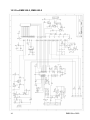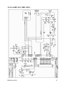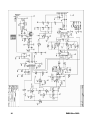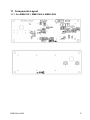
1
KERN & Sohn GmbH
Ziegelei 1
D-72336 Balingen
E-Mail: [email protected]
Tel: +49-[0]7433- 9933-0
Fax: +49-[0]7433-9933-149
Internet: www.kern-sohn.com
Service manual
School balance
KERN EMB
Version 3.3
4/2009
GB
EMB-SH-e-0933
GB
KERN EMB
Version 3.3 4/2009
Service manual
School balance
Table of Contents
1
Basic Information ________________________________________________ 3
2
Features ________________________________________________________ 3
3
Calibration Procedure (CAL) _______________________________________ 4
4
Internal Calibration Procedure (Linearity Adjustment) __________________ 5
4.1
Readout of the Internal Counts _______________________________________ 6
5
Display Segment Test_____________________________________________ 6
6
Functional Block Diagram / Description______________________________ 7
6.1
Functional Block Diagram ___________________________________________ 7
6.2
Function Description _______________________________________________ 8
7
Trouble Shooting ________________________________________________ 9
8
To Replace PCB ________________________________________________ 10
9
To Replace Load Cell Assembly ___________________________________ 11
10 Schematics ____________________________________________________ 12
10.1 For EMB 220-1, EMB 2200-0, EMB 5.2K5 ________________________________ 12
10.2 For EMB 500-1, EMB 1200-1, EMB 5.2K1 ________________________________ 13
10.3 For EMB 200-2, EMB 600-2 ___________________________________________ 14
10.4 For EMB 100-3, EMB 1000-2 __________________________________________ 15
11 Components Layout _____________________________________________ 17
2
11.1
For EMB 220-1, EMB 2200-0, EMB 5.2K5 ______________________________ 17
11.2
For EMB 500-1, EMB 1200-1, EMB 5.2K1 ______________________________ 18
11.3
For EMB 200-2, EMB 600-2__________________________________________ 18
11.4
For EMB 100-3, EMB 1000-2_________________________________________ 19
EMB-SH-e-0933
1 Basic Information
Grundlegende Hinweise
The device must be repaired only by trained specialist staff or personnel with
professional formation (such as a repair-specialist accredited by law
concerning verification).
The service manual is obligatory for repair work.
After repair, original conditions of the device have to be restored.
Only original spare parts should be used.
Das Gerät darf nur von geschultem oder beruflich ausgebildetem
Fachpersonal (z. B. eichrechtlich anerkannter Instandsetzer) repariert werden.
Die Serviceanleitung ist bindend für Reparaturen.
Das Gerät muss nach erfolgter Reparatur wieder in den Originalzustand
zurückversetzt werden.
Es dürfen nur Originalersatzteile verwendet werden.
2 Features
•
•
•
•
•
•
•
•
•
•
•
•
•
Auto zero
Full Tare function
4 weighing units
Display segment test function
Negative value indication
Auto off function (battery mode only, enable / disable)
Zero tracking enable / disable
Two types of Digital Auto Calibration
Solder pads to prevent end-user internal calibration
Low battery indicator
Overload protection / indication
AC adaptable
Operated by 2 x AA size alkaline batteries (EMB220-1, EMB2200-0, EMB5.2K5),
9V battery (EMB100-3, EMB200-2, EMB600-2, EMB1000-2, EMB500-1, EMB1200-1,
EMB5.2K1)
EMB-SH-e-0933
3
3 Calibration Procedure (CAL)
1. Turn scale on by pressing the [ON/TARE] key.
2. Press the [OFF] key for approx. 5 seconds. Display will show [CAL] and then the
required calibration weight.
3. Gently place the correct calibration weight on the center on the weighing pan.
Wait until display shows [ F ] then turn off.
In case [ E] is display instead of [ F], this indicates a calibration procedure error,
unstable or wrong calibration weight applied for calibration.
Turn the scale off and then on and repeat the procedure.
4
EMB-SH-e-0933
4 Internal Calibration Procedure (Linearity Adjustment)
1. Remove the top housing of the scale.
2. Connect the pads below together by soldering:
J1 for EMB 220-1, EMB 2200-0, EMB 5.2K5
J3 for EMB 100-3, EMB 500-1, EMB 1000-2, EMB 1200-1, EMB 5.2K1
J9 for EMB 200-2, EMB 600-2
3. Place scale on a hard level surface. With weighing pan installed, turn scale on.
Display shall show the internal counts.
4. The internal counts shall fall in the range from 3 000 to 5 000.
For EMB 200-2 and EMB 600-2 the internal counts shall fall in the range
from 50 000 to 80 000.
For EMB 100-3 and EMB 1000-2 the internal counts shall fall in the range
from 100 000 to 300 000.
In case out of this range, connect J9 (J4 for EMB 200-2 and EMB 600-2;
J6 for EMB 100-3 and EMB 1000-2) left side or right side to increase or reduce the
reading.
Connecting or disconnecting pads on
J6, J7 or J8 for EMB 220-1, EMB 2200-0, EMB 5.2K5
J5, J6, J7 or J8 for EMB 500-1, EMB 1200-1, EMB 5.2K1
J1, J2 or J3 for EMB 200-2, EMB 600-2
J2, J3, J4 or J5 for EMB 100-3, EMB 1000-2
can fine tune the reading.
5. Press [OFF] key once. Display will show the required calibration weight.
Place the corresponding calibration weight on the center of the weighing pan.
Press [OFF] key while the weight is placed on the weighing pan.
6. Repeat step 5 for other calibration weights until display show [
Remove all weights from weighing pan.
F ] then off.
7. Disconnect the pads below:
J1 for EMB 220-1, EMB 2200-0, EMB 5.2K5
J3 for EMB 100-3, EMB 500-1, EMB 1000-2, EMB 1200-1, EMB 5.2K1
J9 for EMB 200-2, EMB 600-2
8. Turn scale on and check the accuracy at different weight.
9. Install the top housing of scale.
In case [
E ] is display instead of [
F ], this indicates a calibration procedure
error or wrong weight applied for calibration.
Turn the scale off and then on and repeat the procedure.
EMB-SH-e-0933
5
4.1 Readout of the Internal Counts
For example:
Without number
In that case the internal count is 66 063
With number (here 3)
You have to set this number
before the value
In that case the internal count is 321 580
5 Display Segment Test
Whenever the scale is power on, all segments of the LCD will be turn on
for approx. 5 seconds. Check for any missing segment.
6
EMB-SH-e-0933
6 Functional Block Diagram / Description
6.1 Functional Block Diagram
Keyboard
9V/2xAA Battery
or
Adaptor
LCD
Power control /
Regulator &
Low battery
detector
Microprocessor
digital signal
Load cell
(Sensor)
EMB-SH-e-0933
Amplifier
A/D Converter
analog
signal
7
6.2 Function Description
1. Load cell
This is the heart of the whole system. The load cell itself is arranged as a bridge.
The resistance change of the bridge elements is proportional to the load applied
on the load cell. Therefore, the output of the load cell is an analog signal,
which is proportional to the load applied on the scale.
2. Amplifier
The analog signal from the load cell is very small, of the order of micro-volt.
Hence, a linear and stable amplifier is applied to amplify the analog signal
to an appropriate level.
3. A/D Converter
In order for the analog signal can be input to the microprocessor, this part
converts the analog signal to its digital equivalent. The operation of the analog
to digital converter is using a SIGMA DELTA technique and under the control
of the microprocessor.
4. Microprocessor
The microprocessor control all the functions of the scale, such as auto zero,
A/D conversion, timings, weight calculation, display, overload indication,
low battery indication, tare function, etc….
5. Display
This is the part where the weight is shown out on the LCD display in digital form.
The whole display is driven by the microprocessor.
6. Power Regulator and Low Battery Detector
This part contains the ON/OFF power control. In order for the external power can
be used by other parts of the scale, a regulator is used to regulate the supply.
A low battery detector is employed to make sure that the power supply is strong
enough for normal operation of the scale.
7. Keyboard
The keyboard provides on user interface. [On/TARE], [OFF] keys are employed
to operate the scale.
8
EMB-SH-e-0933
7 Trouble Shooting
Power on
↓
Full Segments?
If no display, check battery /adaptor, keys, connection between
battery/adaptor—main board.
If missing segments, check fixing of LCD frame, zebra connector under LCD.
↓
Display Zero?
If display [LO], check battery >2.6v
(>7.5v for EMB 100-3,EMB 200-2,EMB 600-2,EMB 500-1,EMB 1000-2,
EMB 1200-1,EMB 5.2K1)
adaptor>9v.
If display [ E] , check internal count.
↓
Proper readout?
If unstable reading, check weighing plate, overload stopper, load cell and wires,
environmental conditions and stable table.
↓
Correct reading?
If not accurate, perform internal calibration.
If cannot reach full capacity, check weighing plate, overload stopper, load cell
and internal zero point.
If always zero, check internal zero point. Internal calibration if necessary.
↓
Normal operation.
EMB-SH-e-0933
9
8 To Replace PCB
1. Disassemble top housing of scale.
2. Disconnect
PL1, SS1 and flat line of keyboard (EMB 220-1, EMB 2200-0, EMB 5.2K5)
PL1, PL2 and PL3 (EMB 500-1, EMB 1200-1, EMB 5.2K1)
PL1, PL2 and JP1 (EMB 200-2, EMB 600-2)
PL1, PL3, JP2, J1 (flat line) and SENSOR (EMB 100-3, EMB 1000-2)
from the PCB. Disassemble the PCB screw.
Replace a new PCB. Assemble the PCB screw and connect the cables and
the flat line again.
3. Perform internal calibration as described in section 4.
4. Assemble the top housing.
5. Check accuracy of scale at different weight.
EMB 200-2
EMB 600-2
EMB 220-1
EMB 500-1
weight
(g)
tol.
(g)
weight
(g)
tol.
(g)
weight
(g)
tol.
(g)
weight
(g)
tol.
(g)
50.00
0.02
100.00
0.02
50.0
0.2
100.0
0.3
100.00
0.02
200.00
0.02
100.0
0.2
300.0
0.3
150.00
0.02
400.00
0.04
150.0
0.2
500.0
0.3
200.00
0.02
600.00
0.06
200.0
0.2
EMB 1200-1
EMB 2200-0
EMB 5.2K1
EMB 5.2K5
weight
(g)
tol.
(g)
weight
(g)
tol.
(g)
weight
(g)
tol.
(g)
weight
(g)
tol.
(g)
200.0
0.3
500
2
1000
3
1000
10
500.0
0.3
1000
2
3000
3
3000
10
1000.0
0.3
1500
2
5000
3
5000
10
1200.0
0.3
2000
2
EMB 100-3
EMB 1000-2
weight
(g)
tol.
(g)
weight
(g)
tol.
(g)
10.000
0.002
100.00
0.02
20.000
0.002
200.00
0.02
50.000
0.003
500.00
0.03
70.000
0.003
700.00
0.03
100.000
0.003
1000.00
0.03
6. Check other functions, such as Tare and Auto-Off.
10
EMB-SH-e-0933
9 To Replace Load Cell Assembly
1. Disassemble top housing of scale.
2. Disconnect the load cell wires from main PCB. Remove the screws fixing the
bottom plate of the load cell assembly. Replace the load cell with a new one.
Connect the load cell wires and fix the screws.
3. Perform internal calibration as described in section 4.
4. Assemble the top housing.
5. Check accuracy of scale at different weight.
EMB 200-2
EMB 600-2
EMB 220-1
EMB 500-1
weight
(g)
tol.
(g)
weight
(g)
tol.
(g)
weight
(g)
tol.
(g)
weight
(g)
tol.
(g)
50.00
0.02
100.00
0.02
50.0
0.2
100.0
0.3
100.00
0.02
200.00
0.02
100.0
0.2
300.0
0.3
150.00
0.02
400.00
0.04
150.0
0.2
500.0
0.3
200.00
0.02
600.00
0.06
200.0
0.2
EMB 1200-1
EMB 2200-0
EMB 5.2K1
EMB 5.2K5
weight
(g)
tol.
(g)
weight
(g)
tol.
(g)
weight
(g)
tol.
(g)
weight
(g)
tol.
(g)
200.0
0.3
500
2
1000
3
1000
10
500.0
0.3
1000
2
3000
3
3000
10
1000.0
0.3
1500
2
5000
3
5000
10
1200.0
0.3
2000
2
EMB 100-3
EMB 1000-2
weight
(g)
tol.
(g)
weight
(g)
tol.
(g)
10.000
0.002
100.00
0.02
20.000
0.002
200.00
0.02
50.000
0.003
500.00
0.03
70.000
0.003
700.00
0.03
100.000
0.003
1000.00
0.03
6. Check other functions, such as Tare and Auto-Off.
EMB-SH-e-0933
11
10 Schematics
10.1 For EMB 220-1, EMB 2200-0, EMB 5.2K5
12
EMB-SH-e-0933
10.2 For EMB 500-1, EMB 1200-1, EMB 5.2K1
EMB-SH-e-0933
13
10.3 For EMB 200-2, EMB 600-2
14
EMB-SH-e-0933
10.4 For EMB 100-3, EMB 1000-2
EMB-SH-e-0933
15
16
EMB-SH-e-0933
11 Components Layout
11.1 For EMB 220-1, EMB 2200-0, EMB 5.2K5
EMB-SH-e-0933
17
11.2 For EMB 500-1, EMB 1200-1, EMB 5.2K1
EMB 500-1
EMB 1200-1
EMB 5.2K1
11.3 For EMB 200-2, EMB 600-2
18
EMB-SH-e-0933
11.4 For EMB 100-3, EMB 1000-2
EMB-SH-e-0933
19
20
EMB-SH-e-0933