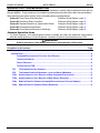
1
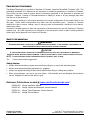
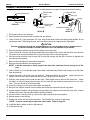
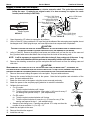
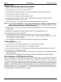
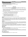
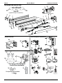
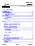
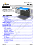
SERVICE MANUAL MIRAGE RV MANUAL/MOTORIZED STANDARD/AUTO-RETRACT/DIRECT RESPONSE These instructions apply to all models listed. Details and procedures unique to a specific model are labeled appropriately. TABLE OF CONTENTS Product Overview .......................................................................................................................... 1 Mirage Patio Awning Specifications........................................................................................................ 1 Canopy Replacement .................................................................................................................... 2 Spring Arm Replacement.............................................................................................................. 3 Replacing the Arm .................................................................................................................................. 3 To Replace the Lead Rail Connector: ................................................................................................. 4 To Replace the Case Arm Support ..................................................................................................... 4 Motor Replacement ....................................................................................................................... 5 Hand Crank Replacement ............................................................................................................. 6 Diagnostics/Troubleshooting ....................................................................................................... 7 Common Operation Items ................................................................................................................... 7 System Tests .......................................................................................................................................... 8 Standard Electronics w/ Optional Auto-Retract ................................................................................... 8 Direct Response w/ DKS Style Switch Panel ...................................................................................... 8 Testing the Key FOB ........................................................................................................................... 9 Electrical ...................................................................................................................................... 14 Wiring Harness – Optional Light & Speaker End Caps ........................................................................ 15 Wiring Diagram - Direct Connect (No Relay Control Box) .................................................................... 15 Wiring Diagram –Switches w/ Relay Control Box - Previous ................................................................ 16 Wiring Diagram –Switches w/ Relay Control Box - Current .................................................................. 17 Wiring Diagram – Standard Electronics w/ Optional Auto Retract ........................................................ 18 Wiring Diagram – Direct Response Electronics .................................................................................... 19 Wiring Diagram – Direct Response Winnebago ................................................................................... 20 Control Board Replacement - Direct Response.................................................................................... 21 Sensor Replacement for Direct Response ........................................................................................... 22 Installing the Vertical Mount Bracket ................................................................................................. 22 Installing a New Sensor .................................................................................................................... 22 Optional Manual Bypass Switch – Direct Response............................................................................. 23 Standard Service Procedures .................................................................................................... 24 Manual Override (motorized versions only) .......................................................................................... 24 Adjusting the Pitch ................................................................................................................................ 24 Setting the Motor Limits ........................................................................................................................ 25 Adjusting the OUT Limit Switch......................................................................................................... 25 Adjusting the IN Limit Switch............................................................................................................. 25 Setting the Wind Speed Sensitivity (standard electronics) ................................................................... 26 Programming the Remote (standard electronics w/ optional remote)................................................... 26 Programming the Remote Receiver (Direct Response) ....................................................................... 27 Operational Notes: ............................................................................................................................ 27 Standard Maintenance ................................................................................................................ 28 Part Number Listing .................................................................................................................... 29 Part Number Configuration ................................................................................................................... 29 Illustrated Parts List .............................................................................................................................. 30 052979-301r9 Printed in USA May, 2013 PROPRIETARY STATEMENT The Mirage Patio Awning is a product of Carefree of Colorado, located in Broomfield, Colorado, USA. The information contained in or disclosed in this document is considered proprietary to Carefree of Colorado. Every effort has been made to ensure that the information presented in the document is accurate and complete. However, Carefree of Colorado assumes no liability for errors or for any damages that result from the use of this document. The information contained in this manual pertains to the current configuration of the models listed on the title page. Earlier model configurations may differ from the information given. Carefree of Colorado reserves the right to cancel, change, alter or add any parts and assemblies, described in this manual, without prior notice. Carefree of Colorado agrees to allow the reproduction of this document for use with Carefree of Colorado products only. Any other reproduction or translation of this document in whole or part is strictly prohibited without prior written approval from Carefree of Colorado. SAFETY INFORMATION WARNING A WARNING INDICATES A POTENTIALLY HAZARDOUS SITUATION WHICH , IF NOT AVOIDED, COULD RESULT IN DEATH OR SERIOUS INJURY AND/OR MAJOR PROPERTY DAMAGE. CAUTION A CAUTION INDICATES A POTENTIALLY HAZARDOUS SITUATION THAT MAY CAUSE MINOR TO MODERATE PERSONAL INJURY AND/OR PROPERTY DAMAGE. IT MAY ALSO BE USED TO ALERT AGAINST UNSAFE PRACTICES. NOTE: A note indicates further information about a product, part, or step. Tip: A tip provides helpful suggestions. Safety Notes: Always disconnect battery or power source before working on or around the electrical system. Always wear appropriate safety equipment (i.e. goggles). Always use appropriate lifting devices and/or helpers when lifting or holding heavy objects. When using fasteners, use care to not over tighten. Soft materials such as fiberglass and aluminum can be "stripped out" and lose the ability to grip. Reference Publications located @ www.carefreeofcolorado.com:' 052979-003 052979-201 052979-211 052979-301 Mirage Installation Manual Mirage, Manual and Motorized, Owner's Manual Mirage, Direct Response, Owner's Manual Mirage Service Manual Carefree of Colorado a Scott Fetzer company 2145 W. 6th Avenue Broomfield, CO 80020 303-469-3324 ♦ www.carefreeofcolorado.com Carefree of Colorado Service Manual MIRAGE PRODUCT OVERVIEW The Mirage Patio Awning offers the coach owner an awning system that provides as much or as little shade as required. The canopies are housed in an aluminum case that easily blends in with the coach side wall. The canopy is made from Sunbrella® fabric. Each unit is equipped with Mirage lateral support arms that are the strongest available on the market. No vertical arms interfere with coach sidewalls or equipment that may be mounted on the sidewalls or sidewall graphics. These arms can also be adjusted to vary the canopy pitch up to 2 feet (it is strongly recommended that service and adjustments be performed by trained technicians). The unique and innovative 110V electronic control system provides Carefree’s Direct Response system with interior pushbutton controls for standard extend/retract functions. When power is ON, the auto-retract system is engaged to automatically retract the awning in windy conditions. Sensitivity can be set to respond to a variety of wind speed conditions. An RF remote is standard with the Direct Response system. MIRAGE PATIO AWNING SPECIFICATIONS The following information is for reference only. 12’ – 21’ [3.66m - 6.4m] (in 1 foot [.305m] increments) LENGTH EXTENSION: 10' [3m] DROP @ MIN. PITCH: 10" [25cm] DROP @ MAX. PITCH: 35" [89cm] Values are approximate, actual dimensions may vary with specific installations. SUPPORT: Lateral Spring Arms 2 for 12' - 18'; 3 for 19' - 21' MOTOR: Tubular Power: CONTROLS: Available in LH or RH configurations 120V, 60Hz, 2.5A Torque: 60nm Speed: 14 RPM Direct ResponseTM Hardware: White or Black Woven Acrylic (refer to sales literature for colors) Fabric: APPROXIMATE WEIGHT (LBS.) Awning Length Weight Dim B Awning Length Weight Dim B Awning Length 12 134 6.5in 15 160 11.25in 19 13 143 16 169 20 14 152 17 177 21 18 186 22 COLOR: A (Awning Length) Back Plate (Awning Case) 1 1/2" (ref) Weight 194 203 211 220 5.57" Dim B 17in 1 1/4" 3" (ref) 8" Mounting Plate (ref) B Lateral Arm Mount (ref) 6 3/8" B MIRAGE007a Figure 1. General Description - Mirage Patio Awning. 052979-301r9 1 MIRAGE Service Manual Carefree of Colorado CANOPY REPLACEMENT During the following instructions, use the manual override procedure on page 24 to open and close the awning. Outer Spring Arms Phillips Head Screw Rubber Well Nut Case End Plate Idler (ref) Canopy Firmly Tie Elbows Together DETAIL A Socket Head Screw (2) End Cap DETAIL B Lead Rail End Plate Lead Rail DETAIL C Mirage038 1. Disconnect power to the awnings. 2. Open the awning several inches to expose the arm elbows. 3. (refer to Detail A) Using a minimum 1/2" rope, firmly tie the elbows of the outer spring arms together, do not use bungee cords. When tying the rope, use a non-slip knot such as a square knot or equivalent. CAUTION 4. 5. 6. 7. 8. FAILURE TO SECURE THE LEAD RAIL AS DESCRIBED WILL ALLOW THE SPRING ARMS TO UNEXPECTANTLY EXTEND OUT POSSIBLY CAUSING PERSONAL INJURY AND DAMAGE TO THE AWNING. Remove the fabric retainer screws in the leading rail and set aside. (refer to Detail B) Remove the phillips head screw and rubber well nut from the top of the case and the (2) socket head screws that attach the end cap from the inside of the awning case. Use the manual override (refer to page 24) to unroll the canopy until the slot in the tube is aligned with the awning case opening. Remove the end plate from the lead rail assembly. Remove the end plate from the awning case. NOTE: It will be necessary to firmly support the roller tube and keep it from coming out of the case. 9. (refer to Detail C) From the idler end of the rollbar, simultaneously slide the old canopy out of the roller tube and lead rail. 10. Inspect the slots in the roller tube and lead rail. Clean and deburr as required. Lightly spraying the inside of the slot with a dry silicone lubricant will aid in sliding the new fabric in. 11. Slide the new canopy into the lead rail and roller. Both edges must be done at the same time. Orient the fabric so that the large polycord goes into the lead rail, the smaller polycord goes into the roller tube. The hem should be on the down side. 12. Center the canopy into the slots of the rollbar and lead rail. 13. Remove any support material from the rollbar and install the case and lead rail end plates. 14. Use the manual override to roll the canopy onto the rollbar, the material rolls under the roller tube. Ensure the fabric rolls evenly onto the rollbar without wrinkling or folding. 15. Once the fabric is snugly rolled up, remove the rope used to tie the arms together. 16. Restore power to the awning. 17. Extend and retract the awning several times. This will allow the canopy to self-center. NOTE: It may be necessary to adjust the motor limits. Refer to page 25. 18. Install the fabric retainer screws in the lead rail. 19. Install the end cap. 2 052979-301r9 Carefree of Colorado Service Manual MIRAGE SPRING ARM REPLACEMENT CAUTION THE SPRING ARM IS UNDER TENSION TO OPEN. USE EXTREME CARE TO FIRMLY HOLD THE SPRING ARMS DURING ASSEMBLY AND DISASSEMBLY TO AVOID ANY SUDDEN OR UNEXPECTED MOVEMENT BY THE ARM. SERIOUS PERSONAL INJURY AND/OR PROPERTY DAMAGE COULD OCCUR. REPLACING THE ARM The following procedure requires two people. 1. Open the awning to the maximum extension or as wide as possible. This is to minimize the spring tension in the arms during this procedure. 2. Disconnect power to the awning. B 3. Use a scaffold, ladder or other means to firmly support the lead rail. 4. For arms with the sensor cable mounted, carefully remove the sensor cable from the wire channel on top of the arm. Use care to not bend, break or compromise the cable. 5. Lead Rail Connector 6mm Adjustment Screw (refer to Detail A) At the lead rail, remove the M121.25 lock washer and nut from the arm and lead rail connector. 6. Slightly loosen the 6mm adjustment screw. DO NOT loosen the outer set screw. 7. Firmly grasp the spring arm and slide the lead rail arm knuckle out of the lead rail connector. Allow the arm to extend to its maximum length outside the lead rail. Have a second person hold or otherwise support the unattached end. 8. A (refer to Detail B) Inside the case, remove the M121.25 x 25 bolt and washer from the side of the arm support. Remove the M12-1.25 x 40 bolt, washer and saddle from the front of the support. 9. Slightly loosen the 6mm locking screw. Rail Knuckle M12-1.25 Washer & Nut Detail A (Lead Rail) Case Arm Knuckle Arm Support M12-1.25 x 25 Bolt & Washer 6mm Locking Screw Saddle M12-1.25 x 40 Bolt & Washer Detail B (Case) Mirage037 10. Firmly grasp the spring arm and slide the case arm knuckle out of the arm support. Set the old arm aside. 11. If the arm has wire channel mounted for the sensor cable, carefully remove the channel from the arm to reuse on the new arm. 12. On the replacement arm assembly, remove the lead rail connector and arm support bracket from the arm knuckles. NOTE: The lead rail connector and arm support bracket are included in case there is damage to the existing brackets. If there is no damage, it is not necessary to replace them with the arm. 13. If replacing the lead rail connector or case arm support, go to page 4 then return to step 14. 14. Using two people firmly hold the new arm assembly and remove the shipping ties. Allow the arm to slowly open to its maximum extension. CAUTION WHEN THE ARM IS CLOSED, IT CAN OPEN WITH SIGNIFICANT FORCE. USE CARE WHEN OPENING THE ARM. Tip: Use a floor or ground cover and place one knuckle and arm half on the ground. Have one person firmly hold the arm half on the ground while the second person carefully opens the other arm half. 052979-301r9 3 MIRAGE Service Manual Carefree of Colorado 15. Lift the arm assembly into position. 16. (refer to Detail B) Slide the case arm knuckle into the support inside the case and secure with 1 each M12-1.25 x 25 bolt and washer and 1 each M12-1.25 x 40 bolt, washer and saddle. Do not tighten at this time. 17. (refer to Detail A) Insert the lead rail arm knuckle into the lead rail connector and secure with 1 each M12-1.25 bolt, washer and nut. Do not tighten at this time. 18. If the sensor cable is routed on the replacement arm: a. Attach a piece of wire channel to the top of each section of the arm. If using new channel, cut each piece slightly shorter than the arm extrusion. Attach the channel using double sided tape. b. Route the cable through the wire channel. At the arm joints, arch the cable slightly to avoid binding. Do not twist the cable. Tip: Use a small tool, such as a flat bladed screwdriver to gently spread open the channel then insert the cable. Do this for the entire length of the channel until the cable is fully inserted. 19. Adjust the arm pitch as required. Follow the procedure for pitch adjustment on page 24. 20. Extend and retract the awning several times. This will allow the canopy to self-center. NOTE: It may be necessary to adjust the motor limits. Refer to page 25. To Replace the Lead Rail Connector: 1. Remove the lead rail end plate. 2. Carefully mark the location of the existing connector. 3. Loosen the 6mm securing screw and slide the existing connector from the lead rail. This is the outer hex screw. 4. Insert the new connector assembly into the lead rail and position at the marks made previously. 5. Tighten the outer 6mm securing screw. 6. Attach the lead rail end plate. To Replace the Case Arm Support 1. Carefully mark the location of the existing support. 2. Remove the end cap if installed. 3. Remove the end plate. For the idler side, slide the end plate off of the roller tube idler and set aside. (Refer to details on page 2.) For the motor side, Support the roller tube and carefully pull the motor and end plate out 3"-4". (Refer to details on page 5.) CAUTIONS WHEN PULLING THE MOTOR OUT OF THE CASE, THE SERVICING TECHNICIAN MUST USE CARE TO NOT BREAK OR DAMAGE THE MOTOR CABLES. WHEN PULLING THE MOTOR, DO NOT LET THE ROLLBAR COME OUT MORE THAN 1"; OTHERWISE THE ROLLBAR IDLER WILL DISENGAGE FROM THE OPPOSITE END PLATE. IF THIS OCCURS, REINSERT THE IDLER INTO THE ENDPLATE BEFORE CONTINUING (REFER TO ILLUSTRATION UNDER CANOPY REPLACEMENT ON PAGE 2 FOR IDLER DESCRIPTION). 4. Loosen the clamping screws on the support and slide the old support out of the case. 5. Insert the new support assembly into the case and position at the marks made previously. 6. Tighten the clamping screws. 7. For an idler side replacement. Reinstall the end plate. Ensure that the idler pin of the roller tube is properly seated. 8. For a motor side replacement. Press the motor back into the rollbar. Ensure that the idler pin of the roller tube is properly seated on the opposite side. Reattach the end plate to the case. 9. Reinstall the end caps if previously installed. 10. Return to step 14 on the previous page. 4 052979-301r9 Carefree of Colorado Service Manual MIRAGE MOTOR REPLACEMENT During the following instructions, use the manual override procedure on page 24 to open and close the awning. Outer Spring Arms Phillips Head Screw Rubber Well Nut Roll Bar (ref) Drive Gear (ref) Motor Firmly Tie Elbows Together DETAIL A Socket Head Screw (2) End Cap DETAIL B Crown (ref) Case End Plate DETAIL C Mirage039 1. Disconnect power to the awning. 2. Open the awning several inches to expose the arm elbows. 3. (refer to Detail A) Using a minimum 1/2" rope, firmly tie the elbows of the outer spring arms together, do not use bungee cords. When tying the rope, use a non-slip knot such as a square knot or equivalent. CAUTION FAILURE TO SECURE THE LEAD RAIL AS DESCRIBED WILL ALLOW THE SPRING ARMS TO UNEXPECTANTLY EXTEND OUT POSSIBLY CAUSING PERSONAL INJURY AND DAMAGE TO THE AWNING. 4. (refer to Detail B) Remove the phillips head screw and rubber well nut from the top of the case and the (2) socket head screws that attach the end cap from the inside of the awning case. NOTE: It will be necessary to firmly support the roller tube to keep it from coming out of the case. 5. (refer to Detail C) Remove the attaching screws then pull the end plate and motor partially out from the awning case. CAUTIONS WHEN PULLING THE MOTOR OUT OF THE CASE, THE SERVICING TECHNICIAN MUST USE CARE TO NOT BREAK OR DAMAGE THE MOTOR CABLES. WHEN PULLING THE MOTOR, DO NOT LET THE ROLLBAR COME OUT MORE THAN 1"; OTHERWISE THE ROLLBAR IDLER WILL DISENGAGE FROM THE OPPOSITE END PLATE. IF THIS OCCURS, REINSERT THE IDLER INTO THE ENDPLATE BEFORE CONTINUING (REFER TO ILLUSTRATION UNDER CANOPY REPLACEMENT ON PAGE 2 FOR IDLER DESCRIPTION). 6. Disconnect the motor wires from inside the coach and pull out or clip the motor wires. If cutting the motor wires be sure to leave enough wire that can be stripped and spliced. 7. Pull the motor out of the roller tube and remove the attaching screws holding the motor to the end plate. Make note of the motor orientation on the end plate. Do not discard the hardware. 8. Remove the drive gear and crown from the old motor and install on the new motor. 9. Attach the new motor to the end plate paying attention to match the orientation from the old motor. 10. Slide the new motor assembly into the roller tube. Ensure that the motor drive gear and crown are properly seated inside the roller tube. 11. Route the new motor wire into the coach and attach (refer to wiring diagrams on pages 15 - 19 for the appropriate control system) or if the wires were cut, splice the new wires to the existing wires. Ensure that the wire colors match (i.e. red to red and black to black). All wiring must conform to NEC (National Electrical Code) and local codes. 12. Attach the end plate to the case. 13. Remove the roller tube support. 14. To test, restore power then extend and retract the awning. 15. It will be necessary to adjust the motor limits. Refer to page 25. 16. After completing the adjustments, install the end cap. 052979-301r9 5 MIRAGE Service Manual Carefree of Colorado HAND CRANK REPLACEMENT NOTE: Replacement crank assemblies have a shorter extension shaft. The eyelet does not extend below the case. If replacing an original crank, it is also necessary to replace the crank handle (crank handle p/n R001564). 1/4-20 x 1 SHC Screw Spacer Attach (qty: 2) #10 x 1 PTH Screw and Well Nut 4.2 x 25mm PPH Screw Endplate Attach (qty: 3) Spring Arms 6.1 x 50mm SHC Screw Crank Attach (qty: 2) Firmly Tie Elbows Together DETAIL A 1. 2. #8 x 1 SHC Screw Spacer Endcap Attach (qty: 2) Crank DETAIL B Mirage050 Open the awning 12" inches to expose the arm elbows. (refer to Detail A) Using a minimum 1/2" rope, firmly tie the elbows of the outer spring arms together, do not use bungee cords. When tying the rope, use a non-slip knot such as a square knot or equivalent. CAUTION FAILURE TO SECURE THE LEAD RAIL AS DESCRIBED WILL ALLOW THE SPRING ARMS TO UNEXPECTANTLY EXTEND OUT POSSIBLY CAUSING PERSONAL INJURY AND DAMAGE TO THE AWNING. 3. (refer to Detail B) Remove the phillips head screw and rubber well nut from the top of the case and the (2) socket head screws that attach the end cap from the inside of the awning case. NOTE: It will be necessary to support the roller tube to keep it from coming out of the case. A rag can be stuffed between the tube and case to temporarily hold the roller tube in place. 4. Remove the attaching screws then pull the end plate and hand crank out from the awning case and roller tube. CAUTION WHEN REMOVING THE CRANK, DO NOT LET THE ROLLER TUBE COME OUT MORE THAN 1"; OTHERWISE, THE ROLLBAR IDLER WILL DISENGAGE FROM THE OPPOSITE END PLATE. IF THIS OCCURS, REINSERT THE IDLER INTO THE ENDPLATE BEFORE CONTINUING (REFER TO ILLUSTRATION ON PAGE 2 FOR IDLER DESCRIPTION). 5. Remove the screws holding the spacer to the end plate. Set parts aside and save. 6. Remove the screws holding the crank to the spacer. Note the hole position and orientation of the parts. Set parts aside and save. 7. Attach the new crank to the spacer using the screws removed previously. 8. Attach the spacer to the end plate paying attention to match the orientation. 9. Calibrate the hand crank. For LH cranks: a) a) Twist the eyelet clockwise until it stops. b) b) Twist the eyelet counterclockwise 4 turns plus (+) 4.5 turns for every 6" Left Hand Crank the awning was opened in step 1. (see sample below). For RH cranks: a) Twist the eyelet counterclockwise until it stops. b) Twist the eyelet clockwise 4 turns plus (+) 4.5 turns for every 6" the awning was opened in step 1. (see sample below). Sample of calculating turns: If awning was opened 12" in step one then the number of turns would be 4 + (2 x 4.5) = 13. 10. Attach the end plate to the case. 11. Remove the roller tube support. 12. Install the end cap. 6 a) b) Right Hand Crank Mirage051 052979-301r9 Carefree of Colorado Service Manual MIRAGE DIAGNOSTICS/TROUBLESHOOTING The following procedures are intended to aid the service technician to logically resolve operational issues with the Mirage installation. These procedures do not address conditions that may arise with the basic awning installation. When procedures are system specific, the four electrical systems are designated as: System #1, Direct Connect (No Relay Box) Reference Wiring Diagram - page 15 System #2, Switches w/ Relay Control Box Reference Wiring Diagram - page 16 System #3, Standard Electronics w/ Optional Auto-Retract Reference Wiring Diagram - page 18 System #4, Direct Response Electronics Reference Wiring Diagram - page 19 System #4, Direct Response Electronics, Winnebago Reference Wiring Diagram - page 20 Common Operation Items 1. For Direct Response: If the optional ignition lockout is installed, the system will disable the extend function while the vehicle ignition key is in the ON position. Operation will return to normal when the key is OFF. WARNING ALWAYS DISCONNECT POWER WHEN CONNECTING OR DISCONNECTING 110VAC WIRES. Procedures in this section: Page COMMON OPERATION ITEMS ..................................................................................................................... 7 SYSTEM TESTS ........................................................................................................................................ 8 STANDARD ELECTRONICS W/ OPTIONAL AUTO-RETRACT ............................................................... 8 TESTING THE REMOTE................................................................................................................... 8 DIRECT RESPONSE ....................................................................................................................... 8 TESTING THE KEY FOB ................................................................................................................. 9 D01 THE AWNING DOES NOT OPERATE .......................................................................................... 10 D02 THE AWNING OPERATES DIFFERENTLY THAN THE SWITCH MARKINGS ...................................... 11 D03A AWNING DOES NOT AUTO-RETRACT IN WIND (STANDARD ELECTRONICS) ................................. 12 D03B AWNING DOES NOT AUTO-RETRACT IN WIND (DIRECT RESPONSE) ........................................... 12 D04A REMOTE DOES NOT OPERATE (STANDARD ELECTRONICS W/ OPTIONAL REMOTE) .................... 13 D04B REMOTE DOES NOT OPERATE (DIRECT RESPONSE) ................................................................ 13 052979-301r9 7 MIRAGE Service Manual Carefree of Colorado SYSTEM TESTS Standard Electronics w/ Optional Auto-Retract 1. Provide 110VAC and 12DC power to the awning system. 2. At the switch panel, turn the POWER SWITCH to "ON". 3. Press the button to extend the awning. The awning will continue to the maximum extension. 4. Pressing the button again will stop the awning. 5. Press the button a third time and the awning will retract. 6. Set the WIND SPEED switch to 12 mph. Refer to Setting the Wind Speed Sensitivity on page 26. 7. Extend the awning using the PATIO switch. 8. Spin the anemometer. The awning should retract automatically to the closed position. NOTE: Do not hit the anemometer to spin. Using compressed air provides a constant pressure source and the output can be regulated to test the various sensitivity settings. DO NOT position the nozzle closer than 10 inches from the cups. 9. Repeat steps 7 and 8 two (2) more times with the Wind Speed switch set to a medium value and then to higher value. 10. Repeat steps 7 through 8 with the Power switch set to OFF. The awning should not move. If the awning does not operate as described: If the awning extends, reverse the red and black motor wires. Refer to the wiring diagram. If the awning does not stop at maximum extend or retract, it may be necessary to adjust the "in" and/or "out" limit switches. Refer to page 25. If the awning does not operate, check the wiring and power according to the wiring diagram. TESTING THE REMOTE 1. Turn the power switch to "ON". 2. On the remote, press and release the down arrow. The awning should extend. 3. Press and release the stop (center) button. The awning should stop. 4. Press and release the up arrow. The awning should retract and stop automatically when fully closed. If the awning does not operate as described: If the awning moves in a direction opposite than described; in the control box, reverse the red and black wires from the motor. If the awning does not operate using the remote; program the remote following the directions on page 26. Direct Response w/ DKS Style Switch Panel When 110VAC power is removed from the system, the controller DOES NOT retain previous positioning information. When power is restored, positioning information is updated when the first function is initiated. The function LEDs (extend, retract and stop) perform a dual function. When the button is pressed, the LED illuminates. The LED stays illuminated during the selected operation and after the awning has fully extended or retracted. This provides an indicator of the awning position. When the stop button is pressed, the LED will illuminate and stay on until a function is pressed. If on, it indicates that the awning is partially extended/retracted. All function buttons are press ON/press OFF. The auto-functions will continue until the awning is fully extended/retracted or when the stop button is pressed. 8 052979-301r9 Carefree of Colorado Service Manual MIRAGE 1. While observing the control panel, have a second person initiate 110VAC power to the coach and awning system. The following should occur: 1.1 The Auto-Retract and Wind Speed LEDs should illuminate briefly then extinguish. 1.2 The Power ON/OFF and function/position LEDs will briefly illuminate. 1.3 The system then goes to the default settings: The POWER “ON”, AUTO-RETRact “ON” and MEDIUM Wind Speed LED will be on. NOTE: The function/position LEDs (extend, stop and retract) will not be illuminated. During power up the controller does not retain position information. The controller is updated with the first function used. 2. Press the POWER “OFF”. ALL LEDs should extinguish. The POWER ON/OFF button disables all functions including Auto-Retract and the optional RF remote if installed. It does not disconnect the 110VAC power. 3. Press the POWER “ON”. Press the EXTEND button, the LED should illuminate while the awning extends and stay on after the awning auto-stops. Observe the awning, it should fully extend. The system performs an auto-tension action when the awning is fully extended. The awning rolls in reverse to tension the fabric. The auto-tension feature works only with the extend function when the awning is fully extended or the stop button is pushed while extending. 4. After the awning is fully extended, press the RETRACT button, the EXTEND LED should extinguish and the Retract LED should illuminate while the awning is retracting. Press the STOP button. 5. When the STOP button is pressed, the awning will stop, the RETRACT LED should extinguish and the STOP LED should illuminate. 6. Press the RETRACT button, allow the awning to retract fully, the Retract LED will illuminate and stay lit. 7. Press the AUTO-RETRACT OFF. The AUTO-RETRACT and WIND SPEED LEDs should go out. 8. Press the AUTO-RETRACT ON. Press each Wind Speed button and confirm that the LEDs illuminate. 9. Test the Auto-Retract function: 9.1 Fully extend the awning. 9.2 With the AUTO-RETRACT ON, set the WIND SPEED to the lowest setting. 9.3 Create a firm but gentle rocking motion with the leading edge of the awning. The awning should retract after 2-3 seconds of the motion. 10. If the optional Ignition Sensor is installed: 10.1 Partially retract the awning. 10.2 Turn the ignition key ON. 10.3 Press the EXTEND button. The LED should flash for 2 seconds then shut off and the previous function LED will come back on. Testing the Key FOB 1. Ensure that the system is OFF at the switch panel. 2. Press each button on the Key FOB. The awning should not move. 3. Turn the system on. 4. Press and release the EXTEND button. The awning should extend automatically. 5. Press and release the RETRACT button on the Key FOB. The awning should retract automatically. 6. While the awning is retracting, press and release the STOP button on the Key FOB. The awning should stop when the button is pushed. 052979-301r9 9 MIRAGE Service Manual Carefree of Colorado In the charts below, YES is a positive response to the test; NO is a negative response. D01 A B THE AWNING DOES NOT OPERATE Confirm 110VAC power to control box. 1. Shut off power source. 2. Open control box. 3. On some early units a fuse is installed on the circuit board (if installed). Check that fuses on circuit boards are intact. 4. Check that 110VAC connections are correct and secure. Refer to correct system schematic. Confirm awning motor is functioning 1 1.1 With power off, disconnect motor wires and AC power in from switches (system #1) or control box. 1.2 Connect awning motor directly to 110VAC power source. Motor White to Neutral (White) of AC cord Motor Green to Ground (Green) of AC cord Motor Red & Black are Motor Direction Control – connect Red to AC Hot (Black). 1.3 While observing awning, briefly apply power. 1.4 Disconnect power and attach other motor direction control wire (Black) to AC Hot (Black). 1.5 While observing awning, briefly apply power. 1.6 Does awning move when power is applied? Note: If the awning runs but does not extend or retract completely, it may be necessary to adjust the motor limits (refer to page 25). 2 Test continuity and connections of motor wire between control box and junction box. YES NO Power is present; go to test B Check vehicle circuits and fuses. Repair as required and retest YES Awning motor is good, control circuit is defective – test and repair For System #1, 2, 3 – Go to Step C For System #4 – Go to Step D Go to step B-2 NO YES NO C Test Control Switches (Systems #1, 2, 3 Only) This test requires the use of a continuity tester. 1. Disconnect wires from switch to be tested. 2. Attach the first probe to the common (center) terminal; attach the second probe to the second terminal. 3. With switch in neutral or off position, does meter indicate an open circuit? 4. Activate switch, does meter indicate a closed circuit? 5. For double direction switches, move the second probe to the third terminal and repeat step 4. YES NO Continuity is good, motor is defective – replace Repair wire as required and retest Switches are good, control box is defective – replace NOTE: Relay box for system #2 is no longer available. It will be necessary to replace with system #3 control box and switches. Follow the diagram on page 18. If answer to any of question (3 – 5) is no, switch is defective – replace. D01 Continued on next page 10 052979-301r9 Carefree of Colorado D01 D Service Manual MIRAGE THE AWNING DOES NOT OPERATE (continued from previous page) Test Key pad (System #4 – Direct Response Only) 1 Confirm 110VAC power to control box 1.1 Shut off power source. 1.2 Open control box. 1.3 On some early units a fuse is installed on the circuit board. Check that fuses on circuit boards are intact. 1.4 Check that 110VAC connections and splices to board is correct and secure. Refer to system schematic. 1.5 While observing the circuit boards, have power restored. The LEDs on the boards should blink red then green. 2 Press the "Power On" button on the touch-pad. The "Power On" LED should illuminate. 3 4 Check the cable between the switch and control box. As a continuity check, Pin 1 of connector 1 goes to Pin 1 of connector 2; pin 2 goes to pin 2; pin 3 goes to pin 3 and pin 4 goes to pin 4. Check the function of the Key pad 4.1 On the control board, locate the terminal strip next to the phone cord connectors. 4.2 Insert 3 wires into the terminals shown below 4.3 While observing the awning, short the wire ends between the Common and Extend terminals. Does the awning move? 4.4 Short the wire ends between the Common and Retract terminals. Does the awning move? YES NO Power is present; go to test B Check vehicle circuits and fuses. Repair as required and retest YES NO Power is on, go to step D-4 LED does not illuminate, go to step D-3 Continuity OK; go to step D-4 Replace cable and retest YES NO YES NO Control Board is good, Key pad is defective - replace Control Board is defective – replace control box. Retract Extend Common MIRAGE040 D02 THE AWNING OPERATES DIFFERENTLY THAN THE SWITCH MARKINGS This condition generally occurs during new installations or when major components have been replaced. YES Motor wires from awning are A Does Awning operate in reverse of the switch plate labeling (i.e. extends when retract is pushed)? reversed - locate motor wires in the control box, reverse the red and black wires. 052979-301r9 11 MIRAGE Service Manual Carefree of Colorado D03A AWNING DOES NOT AUTO-RETRACT IN WIND (STANDARD ELECTRONICS) NOTE: For standard electronics with the optional auto-retract anemometer; the auto-retract system is always on. Confirm that the sensitivity is set correctly (if set on highest level, system may appear not to function). Setting the sensitivity is in the Owner's manual and on page 26. YES Function works using the switch; go to A Confirm that the retract function works using the PATIO switch test B NO Function does not work with switch; go to procedure D01 B Test Anemometer 1 Do the anemometer cups spin freely? YES Go to step B2 NO Anemometer defective - replace 2 Test signal from anemometer: YES Control Box is defective - replace 2.1 Remove anemometer wires from control box; NO The circuit stays open or stays closed; 2.2 Place continuity tester between anemometer go to step B3 wires; 2.3 Have a helper slowly turn the anemometer: Does the circuit open and close? It should open and close once for every revolution. 3 Test the wire continuity between the control box and the YES Continuity OK; replace anemometer anemometer. NO Repair or Replace wires as required D03B AWNING DOES NOT AUTO-RETRACT IN WIND (DIRECT RESPONSE) A Press the power on button then press the auto-retract button. Does the auto-retract LED flash? YES NO B Confirm that the retract function works using the push buttons. YES NO C 12 Test Motion Sensor 1 Confirm cable is plugged into connector on box marked “Shaker” 2 2.1 Unplug sensor from control box. 2.2 Connect a second sensor into control box. 2.3 Set the control switches for the auto retract function 2.4 Hold the second sensor horizontally and gently move up and down. YES NO YES NO The flashing LED indicates that the sensor has been disengaged or otherwise disabled. Go to step C. Function does not work with switch; go to procedure D01 Function works using the switch; go to test C Function does not work with switch; go to procedure D01 Go to step 2 Correct as required and test. Awning retracts; original sensor defective - replace Awning does not retract; control box defective - replace 052979-301r9 Carefree of Colorado Service Manual MIRAGE D04A REMOTE DOES NOT OPERATE (STANDARD ELECTRONICS W/ OPTIONAL REMOTE) 1 Confirm normal operation with switches 2 4 Confirm batteries in remote are good. Pressing any button on the remote will illuminate the LED indicator on the remote Confirm that the receiver is programmed for the remote 5 Program a second remote and test If system does not operate, go to test D01 Replace as needed -YES NO Refer to “Programming the remote on page 26 and retest. If system does not work; go to step 4 2nd remote works. 1st remote is defective. 2nd remote does not work; control box receiver is defective - replace D04B REMOTE DOES NOT OPERATE (DIRECT RESPONSE) 1 Confirm normal operation with touch pad 2 YES 3 Check the cable between the RR24 and control box. As a continuity check, Pin 1 of connector 1 goes to Pin 1 of connector 2; pin 2 goes to pin 2; pin 3 goes to pin 3 and pin 4 goes to pin 4. Cable must be plugged into the "BUS" port of controller #1. Confirm that the RR24 is programmed for the Remote 4 Program a second remote and test YES NO -- NO 5 Replace the Receiver and test. (it will be necessary to program receiver for remote) YES NO 6 Replace control box 052979-301r9 If system does not operate, go to test D01 Cable is OK. Confirm that cable is securely plugged in; go to step 4 Repair or Replace cable as required. Refer to “Programming the Receiver” on page 27 and retest. If system does not work; go to step 5 2nd Key FOB works. Replace battery in 1st Key FOB and retest, if no response, 1st Key FOB is defective. 2nd remote does not work; go to step 6 System works OK. 1st receiver is defective System does not work. Reinstall 1st receiver; go to step 7 -- 13 MIRAGE Service Manual Carefree of Colorado ELECTRICAL IMPORTANT NOTICES: Failure to follow the wiring instructions in this publication may void the motor warranty. All wiring must conform to NEC (National Electrical Code) and local codes. DO NOT wire two or more motors to one switch—No parallel wiring. The SO cable from the 110VAC awning motor can only pass directly through a wall, it can not be laid up in the wall and must be connected to NM wire or individual wires in conduit no more than 6 inches past the point of entry. For 110VAC installations, enclosed junction boxes are required for all wire splices and direct connection switch installations. Boxes are required in conformance with prevailing construction codes. The servicing technician or installer is required to furnish the flush mounted, UL approved electrical duplex boxes where required. The 110V electronic control system provides the user with simple pushbutton controls for the awnings installed. Four configurations are available: WARNING ALWAYS DISCONNECT THE VEHICLE BATTERY AND ELECTRICAL SOURCES BEFORE WORKING WITH ELECTRICAL WIRING AND COMPONENTS. 1) Direct Connect (reference as system #1). 110VAC is routed directly through the switches to the awning motor. System includes: 1 power switch and 1 patio (extend/retract) switch. This system is no longer offered. 2) Optional Relay Box (reference as system #2). 110VAC power is controlled by a relay control box. The switches use a 12VDC signal to control the relays. Switch installation is simplified; the switches do not require a duplex box. System includes: 1 power switch, 1 patio (extend/retract) switch and 1 relay control box. This system is no longer offered. 3) Standard Electronics w/ Optional Auto-Retract (reference as system #3). The optional auto-retract system detects adverse wind conditions and retracts the awning. Sensitivity is set by the user. Standard system includes: 1 power switch, 1 patio (extend/retract) switch, 1 control box An optional anemometer is available for the auto-retract system; and An optional remote control is available. 4) Direct Response (reference as system #4). The 110V electronic control system provides the user with simple pushbutton controls for the awning. The Direct Response electronic system is a premier autoretract system that detects motion from adverse wind conditions and retracts the awning. Sensitivity is set by the user System includes: Control box, Master control panel (w/ pushbutton awning control and windspeed sensitivity setting), motion sensor. An optional RF remote control is available with the Direct Response system. An optional ignition lockout is available. The switches use a 5VDC signal to operate the control box; thus eliminating the need for a junction box for the control panel. Components are connected using terminated cables. Terminated cable is 4-wire RJ11 terminated phone cord (straight, no twist). This does not include 110VAC power in or awning motor power. 14 052979-301r9 Carefree of Colorado Service Manual MIRAGE WIRING HARNESS – OPTIONAL LIGHT & SPEAKER END CAPS (THIS SYSTEM IS NO LONGER AVAILABLE) +12VDC Stereo Consult Stereo Manual for Speaker Connections Shielded Outdoor Speaker Grade Wire 16 AWG UL Listed Outdoor Grade Wire 16 AWG UL Listed Motor Side Idler Side Mirage041 WIRING DIAGRAM - DIRECT CONNECT (NO RELAY CONTROL BOX) SYSTEM #1 (THIS SYSTEM IS NO LONGER AVAILABLE) To 110VAC Green White Black Green White Black Red 2 Conductor 14AWG NM Wire w/ Ground 1 2 4 6 8 3 5 7 Power Switch 1 3 2 4 6 8 5 7 Patio Switch 3 Conductor 14AWG NM Wire w/ Ground Green White Black Red UL Approved Junction Box Install per Construction Code Installer Furnished From Motor Red Black A 1 3 2 4 6 8 5 7 Patio Switch Detail A For LH Configuration Reverse Red & Black Wires on Switch Terminals 1 & 7 MIRAGE015 052979-301r9 15 MIRAGE Service Manual Carefree of Colorado WIRING DIAGRAM –SWITCHES W/ RELAY CONTROL BOX - PREVIOUS SYSTEM #2 - The current configuration of this switch configuration has been updated to use R019468-006 switch kit. For switch replacement use R019468-006 kit and the wiring diagram on the next page. 1 3 5 7 6 8 7 5 Power Switch 2 4 6 8 1 2 3 4 5 6 7 8 9 10 Patio Switch +12VDC A Red 2 4 Black 1 3 Detail A For LH Configuration Reverse Red & Black Wires on Terminals 4 & 5 1 2 3 4 5 6 7 8 9 10 12VDC Ground From Motor Red Black Green White Red Black Green White Black White Ground To 110VAC 2 Conductor 14AWG NM Wire w/ Ground 3 Conductor 14AWG NM Wire w/ Ground MIRAGE016 Patio Switch Power Switch Motor AC Power Source 16 FROM Terminal 1 Terminal 7 Terminal 6 Terminal 8 Red Black Ground White Ground White Black TO (RH CONFIGURATION) Control Box Terminal 1 Terminal 2 Patio Switch Terminal 3 12VDC Power Source Control Box Terminal 4 Terminal 5 Terminal 6 Terminal 8 Control Box Terminal 7 Terminal 9 Terminal 10 TO (LH CONFIGURATION) Control Box Terminal 1 Terminal 2 Patio Switch Terminal 3 12VDC Power Source Control Box Terminal 5 Terminal 4 Terminal 6 Terminal 8 Control Box Terminal 7 Terminal 9 Terminal 10 052979-301r9 Carefree of Colorado Service Manual MIRAGE WIRING DIAGRAM –SWITCHES W/ RELAY CONTROL BOX - CURRENT SYSTEM #2 +12VDC Extend/Retract Rear View of Switch On/Off Red A Black 1 2 3 4 5 6 7 8 9 10 Detail A For LH Configuration Reverse Red & Black Wires on Terminals 4 & 5 1 2 3 4 5 6 7 8 9 10 12VDC Ground From Motor Extend/Retract Switch ON/OFF Switch Motor AC Power Source Red Black Green White FROM Upper Terminal Lower Terminal 1st Terminal1 2nd Terminal1 Red Black Ground White Ground White Black Red Black Green White 3 Conductor 14AWG NM Wire w/ Ground TO (RH CONFIGURATION) Terminal 1 Control Box Terminal 2 Extend/Retract Center Terminal Switch 12VDC Power Source Terminal 4 Terminal 5 Control Box Terminal 6 Terminal 8 Terminal 7 Control Box Terminal 9 Terminal 10 Black White Ground To 110VAC 2 Conductor 14AWG NM Wire w/ Ground MIRAGE016a TO (LH CONFIGURATION) Terminal 1 Control Box Terminal 2 Extend/Retract Center Terminal Switch 12VDC Power Source Terminal 5 Terminal 4 Control Box Terminal 6 Terminal 8 Terminal 7 Control Box Terminal 9 Terminal 10 NOTES: 1. Wires to ON/OFF Switch are not pin specific. 2. The SO cable from the 110VAC awning motor can only pass directly through a wall, it can not be laid up in the wall and must be connected to NM wire or individual wires in conduit no more than 6 inches past the point of entry. 052979-301r9 17 MIRAGE Service Manual Carefree of Colorado WIRING DIAGRAM – STANDARD ELECTRONICS W/ OPTIONAL AUTO RETRACT SYSTEM #3 (THIS SYSTEM IS NO LONGER AVAILABLE) A GND UP DOWN COM +12VDC Green Red Black White 3 Conductor 14AWG NM Wire w/ Ground NEUT HOT Black Green White Wires for Anemometer are not pin specific 2 Conductor 14AWG NM Wire w/ Ground 12VDC Ground 1 3 5 7 Power Switch From Motor Installer Furnished Junction Box WIND COMMON To110 VAC Green Red Black White Anemometer Wires for Patio Switch are not pin specific 2 GND 4 UP 6 DOWN 8 Patio Switch COM Green Black Red White NEUT HOT Detail A For RH motor configurations: Red Motor Wire goes to “DOWN” Terminal Black Motor Wire goes to “UP” Terminal Mirage031 18 052979-301r9 Carefree of Colorado Service Manual MIRAGE WIRING DIAGRAM – DIRECT RESPONSE ELECTRONICS 3 Conductor 14AWG NM Wire w/ Gnd AMD grn 6 DSK EYE AUX SUN 2 Conductor 14AWG NM Wire w/ Gnd wht blk 1 Wire Legend: 4 Key Pad grn NOTES: UP Remote wht blk To 110VAC Ignition Lockout Sensor (Optional) Splitter Sensor RH Motor Wire Shown See Detail A for LH Motor RED 1 BLK 2 WHT 3 4 5 GRN 6 7 12VDC Ground Sensor Program Mode Awning #1 RED BLK WHT GRN RF Receiver Press to Learn Transmitter 3 Ignition Switched +12VDC TO EYE PORT on RP24 5 BLK 1 RED 2 WHT 3 4 5 GRN 6 7 Patio Auto-Retract On/Off Wind Speed High Power On/Off Ribbon Cable Extend Stop Retract Low Detail A For LH Configuration Reverse Red & Black Wires Wind Speed Rear View Switch Panel 5 Red Detail B Black Used thru 2006 White Green (Ground) For RH Motor Configurations: Motor Red goes to Pin (1); Motor Black goes to Pin (2) For LH Motor Configurations: Motor Red goes to Pin (2) Black; Motor Black goes to pin (1) The SO cable from the 110VAC awning motor can only pass through a wall, it cannot be laid up in the wall and must be connected to NM wire or individual wires in conduit no more than 6 inches past the point of entry. Splitter is used only when Optional Lock-Out Sensor is installed. Connect RF Receiver directly to “EYE” if Lock-Out is not installed. Wires for the Ignition Lock-Out Sensor are not pin specific. 6 For early units: Label “DSK” was “ACC”; Label “EYE” was “BUS”; Label “AMD” was ”SHAKE” 2 3 4 DR012a Figure 2. Wiring Diagram – Direct Response System. FROM TO (RH CONFIGURATION) TO (LH CONFIGURATION) Motor Red Control Box Control Box 1 2 Black 2 1 White 3 3 Ground 6 6 AC Power White Control Box 4 Control Box 4 Source Black 5 5 Ground 7 7 Awning Sensor 10’ Cable Control Box “AMD” Control Box “AMD” Switch Assy 60“ Cable Control Box “DSK” Control Box “DSK” Splitter 60" Cable Control Box "EYE" Control Box "EYE" Receiver 60” Cable Splitter Splitter Ignition Lockout 60“ Cable Splitter Splitter Notes: 1. Cable lengths are the lengths of the furnished cables. If a connection requires a length greater than the supplied cable, the installer must provide a terminated jumper cable from the box location to the cable end. 052979-301r9 19 MIRAGE Service Manual Carefree of Colorado WIRING DIAGRAM – DIRECT RESPONSE WINNEBAGO Ignition Switched +12VDC 12VDC Ground OEM Lockout Harness RF Receiver Wires to Ignition Lockout are not pin specific Program Mode Press to Learn Transmitter Ignition Lockout Sensor TO EYE PORT on RP24 Awning Keypad UP RED BLK WHT GRN Sensor Splitter Coupler OEM Keypad Harness Green Red Black AMD SUN AUX EYE DSK Yellow Green Red Black grn wht blk GRN RED BLK WHT Yellow Cables are 4-wire RJ11 terminated phone cord (straight, no twist). Red Yellow Motor Wire Pigtail To 110VAC Green Black Wires enter rear of connectors as shown DR030 Mating Connectors: Ignition Lock Out Harness - AMP female 2 pin Mat-N-Lok p/n 1-480699-0; 18-24 ga. pin p/n 350689-1. Key Pad Harness - Molex 4 pin Minifit Jr p/n 39-01-2040; 18-24 ga. female terminal p/n 39-00-0039. 20 052979-301r9 Carefree of Colorado Service Manual MIRAGE CONTROL BOARD REPLACEMENT - DIRECT RESPONSE When a control board fails, it is possible to replace the board. It is not necessary to replace the complete control box assembly. CAUTION THE PROCEDURE REQUIRES HANDLING THE PRINTED CIRCUIT BOARD. TO AVOID INCIDENTAL DAMAGE FROM STATIC DISCHARGE, THE TECHNICIAN SHOULD GROUND THEIR SELF TO DISSIPATE ANY STATIC ELECTRCITY BEFORE OPENING THE PACKAGE OF THE NEW BOARD. FOR DISASSEMBLY AND ASSEMBLY, USE ONLY HAND TOOLS. DO NOT USE POWER EQUIPMENT. Control Board Loctite 29005 Spring Loaded Terminal Block A Screw (qty: 4) Spacer (qty: 4) Screw Type Terminal Block DETAIL A DR027 Figure 3. Replacing a Control Board. NOTES: a. The illustration shows the flat square enclosure. The procedure is valid for all enclosure styles including the single and double rectangular enclosures. b. For reference, use the appropriate Direct Response wiring diagram on page 19. c. (Detail A) On older boards, power and motor wires were connected using a spring loaded terminal block. Newer and replacement boards use a screw type terminal block. Wire connections are the same for both (i.e. motor ground wire goes to terminal 6). d. For early units: Label "DSK" was "ACC"; Label "EYE" was "BUS"; Label "AMD" was "Shake". 1. Disconnect the AC power to the control box. 2. Remove the lid from the control box and set aside. 3. Disconnect all wires and cables from the board to be replaced. Mark and tag the wires. The wires must be connected to the replacement board in the same configuration as removed from the old board. 4. Remove the four screws, circuit board and spacers (if used) from the enclosure. Set screws and spacers aside. 5. Install the replacement board in the enclosure. For rectangular enclosures use the existing screws. The board seats on top of the molded posts and does not require spacers. For the square enclosures, new screws and spacers are included with the replacement board. Spacers are required to provide clearance from the mounting board. 6. Connect the wires and cables to the new board. (Refer to notes above). 7. Restore AC power to the awning systems and test operation. 8. After testing, use Loctite 29005 or equivalent to secure screws in terminal block. 9. Reattach the lid to the control box. 052979-301r9 21 MIRAGE Service Manual Carefree of Colorado SENSOR REPLACEMENT FOR DIRECT RESPONSE NOTE: The original Direct Response Shake Sensor was mounted horizontally on the inside of the lead rail. For product integrity, sensors are now mounted vertically. If replacing an original horizontally mounted sensor, it is necessary to install the vertical mounting bracket for the replacement sensor. Replacement sensors must be mounted vertically and will not work properly if mounted horizontally. #6 x 3/8 Screw (qty: 2) Lead Rail (ref) PC Board (ref) Cable Gland Clamping Nut Vertical Mounting Bracket End Plate (ref) Cable Connector DETAIL B Sensor (ref) #10 x 3/4 Screw (qty: 2) DETAIL A Completed Installation Mirage043 Figure 4. Replacing the Sensor. Installing the Vertical Mount Bracket (Detail A) 1. Remove the lead rail end plate and set aside. 2. Detach the existing sensor. The sensor is attached with a strong double sided adhesive tape. It will be necessary to use a putty knife or similar tool to carefully pry the sensor off. Use care to not bend or otherwise damage the lead rail. Allow the sensor to hang from the cord. DO NOT CUT THE SENSOR CABLE. 3. Use an acetone solvent and clean any glue residue from the inner surface of the lead rail. Follow the solvent manufacturer's directions. 4. The sensor is secured to the new bracket with a #10 x 3/4 screw on each side of the bracket. Insert one (1) screw into the edge of the bracket that will be pointed to the inside of the lead rail. 5. Slide the new vertical mount bracket into the grooves of the lead rail. Position in the approximate location of the old sensor. 6. Secure the bracket with two (2) #6 x 3/8" screws through the top of the bracket. Installing a New Sensor (Detail B) The replacement sensor is furnished with a 25 foot cable. The cable is furnished in case the installed cable has been damaged or compromised. CAUTION DO NOT ATTEMPT TO CUT AND SPLICE THE CABLE. IF DAMAGED, THE CABLE MUST BE REPLACED TO ENSURE SYSTEM INTEGRITY. REMOVING THE OLD SENSOR 1. After detaching the sensor from the lead rail, loosen the clamping nut on the wire gland. 2. Unscrew the wire gland from the sensor case and slide down the wire and out of the way. 3. Remove the back of the sensor case to reveal the PC board. 22 052979-301r9 Carefree of Colorado Service Manual MIRAGE 4. Carefully remove the board from the case. In some instances, the board may be tacked with adhesive and must be pried out. Use care to not damage the cord or connector. 5. Disconnect the cable from the board and slip the connector out of the case. Set the old sensor parts out of the way. 6. Test the integrity (continuity) of the installed cable. Several cable testers are commercially available. If the cable is faulty, go to "Replacing a Sensor and Cable". If the cable is OK go "Installing a Sensor Only". REPLACING A SENSOR AND CABLE 1. Remove the existing cable. Pay particular attention to the routing and attachment points of the existing cable. 2. Slide the new sensor into the vertical mounting bracket and secure with a #10 x 3/4 screw as shown. 3. Route the new cable and sensor to the control box. Arch the cable slightly at the arm joints to avoid binding. Tip: Use a small tool, such as a flat bladed screwdriver, to gently spread open the channel then insert the cable into the channel. Do this for the entire length of the channel until the cable is fully inserted. INSTALLING A SENSOR ONLY: 1. On the new sensor, loosen the clamping nut on the wire gland. 2. Unscrew the wire gland from the sensor case and slide down the wire. 3. Remove the back of the sensor case to reveal the PC board. 4. Carefully remove the board from the case. 5. Disconnect the cable from the board and slip the connector out of the case. 6. Slide the connector of the installed cable into the new sensor case. 7. Attach the wire gland to the case. Do not tighten the clamping nut at this time. 8. Attach the cable to the new board. 9. Reassemble the new sensor. 10. Tighten the cable gland clamping nut. 11. Slide the new sensor into the vertical mounting bracket and secure with a #10 x 3/4 screw as shown. OPTIONAL MANUAL BYPASS SWITCH – DIRECT RESPONSE Installers may elect to install a manual bypass switch for testing or emergency operation of the awning. The simple switch allows the operator to extend or retract the awning without using the keypad control panel. For multiple awning installations, a separate switch must be installed for each awning. 1. Open the control box and identify the terminal block next to the phone cord jacks. Common Extend Retract 2. Connect the switch to the terminal block as shown in the Manual Switch Single Pole, Double diagram. Throw, Momentary ON, The switch is a single pole, double throw, momentary ON, center OFF. Components are installer furnished. Center OFF DR011 Figure 5. Manual Bypass Switch. 052979-301r9 23 MIRAGE Service Manual Carefree of Colorado STANDARD SERVICE PROCEDURES MANUAL OVERRIDE (MOTORIZED VERSIONS ONLY) If 110V power is not available to the coach, the Mirage awning can still be safely retracted using the manual override. The bypass may be accessed from inside the case on the motor housing or from the top of the case above the motor housing. Wall Remove Screw and Rubber Well Nut to Access Manual Overide (7mm Hex) To use the inside bottom access: The awning must be open a minimum of 8” to afford access to the override. To use the top bypass access: Remove the screw and well nut that is used to secure the end cap. 1. Chuck the 7mm hex key into a 3/8” battery powered drill. 2. Insert the hex key into the manual override on the awning. For the top access, it will be necessary to locate the hex by feel; it is not visible with the key inserted in the hole. 3. Operate the drill in the forward (clockwise) direction to close the awning. Reverse the drill to open the awning. Top View 7mm Hex Manual Override Bottom View Wall MIRAGE028 Figure 6. Manual Override Access. NOTE: When using the bottom override, the awning can only be closed within 6-8”. It will be necessary to use the top access to close the awning completely. 4. When done, return the screw and well nut to the top of the case if removed. ADJUSTING THE PITCH CAUTION DURING INSTALLATION OR WHEN THE PITCH OF THE AWNING IS ADJUSTED, IT IS IMPORTANT THAT THE LEAD RAIL IS PARALLEL TO THE AWNING HOUSING. 1. 2. Extend the awning fully. 3/4” Adjustment Nut On one end, loosen the 6mm hex screw located on the spring 3/4” Nut arm knuckle. On Side of Knuckle 3. SLIGHTLY loosen the 3/4” nut on the side of the knuckle. 4. Turn the 3/4” adjustment nut located on the bottom of the knuckle. 6mm Hex Screw CLOCKWISE raises the pitch, COUNTERCLOCKWISE lowers the pitch. Coach Wall NOTE: When raising the pitch, it is helpful to have a second person lift up on the lead rail. 5. Repeat steps 2 through 4 for the other end. Note the caution Lead Rail (ref) information above. 6. When the pitch adjustments are completed, tighten the 6mm screw and the 3/4” nut on the side of the knuckle. When the pitch is adjusted, it is necessary to adjust the angle of 6mm Hex Screw the lead rail for the awning to close correctly. 3/4” Nut MIRAGE024 7. SLIGHTLY loosen the 3/4” nut on the side of each arm knuckle on the lead rail. Figure 7. Pitch Adjustment. 8. Turn the INSIDE 6mm hex screws of each knuckle to increase or decrease the angle of the lead rail. The face of the lead rail should be parallel with the coach wall. 9. When the lead rail adjustments are completed, tighten the 3/4” nut on the side of the knuckles. 24 052979-301r9 Carefree of Colorado Service Manual MIRAGE SETTING THE MOTOR LIMITS The motor limit switches are preset at the factory for best operation of the awning. The “OUT” limit switch is used to stop the motor when the awning is fully extended. The “IN” limit switch is used to stop the motor when the awning is fully retracted. Decrease Run Time Decrease Run Time Increase Run Time “OUT” Limit Switch “IN” Limit Switch Previous Configuration Decrease Run Time Previous Configuration Decrease Run Time “IN” Limit Switch “OUT” Limit Switch Increase Run Time Current Configuration Increase Run Time LH Motor RH Motor Wall Increase Run Time Current Configuration MIRAGE023 Figure 8. Motor Limit Switches. The limit switches are located inside the case, near the end cap. It is necessary to extend the awning to access the switches. NOTE: There are two (2) motor limit switch configurations. Before making adjustments, visually inspect the limit switches to determine which configuration is installed in the awning. Use the illustration above to determine the correct turning direction for the adjustments. Adjusting the OUT Limit Switch NOTE: During normal operation, the awning will extend out then roll back slightly to tension the fabric. 1. Extend the awning out completely. 2. Confirm that the arms are fully extended. The motor should stop and the fabric should be tight. 3. If the motor continues to run, the fabric will sag; use a 4mm allen wrench to turn the "OUT" limit switch to DECREASE the motor run time. 4. If the motor quits before the arms are extended; use a 4mm allen wrench to turn the "OUT" limit switch to INCREASE the motor run time. NOTE: It is best to make the adjustments in increments of a single turn. 3 full turns of the screw equals approximately 2” of fabric extension. 5. Extend and retract the awning several times to confirm that the adjustment is correct. 6. Repeat as required until the awning extends correctly. Adjusting the IN Limit Switch NOTE: The “IN” limit switch is not adjusted when the Direct Response system is installed. The system electronics monitors the motor and shuts the motor off when the awning is fully retracted. If the IN limit switch is accidentally adjusted, the motor may shut off before the awning is fully closed. If this occurs, turn the "IN" adjustment screw to INCREASE the motor run time. It is not necessary that the screw matches the closed position. The Direct Response electronics control the closed position. NOTE: It is normal for the lead rail to slightly relax after the awning closes completely. 052979-301r9 25 MIRAGE Service Manual Carefree of Colorado For motorized awnings w/ standard electronics: 1. Retract the awning in completely. 2. Confirm that the arms are fully retracted. The motor should stop when the awning is fully retracted. If the motor continues to run; or, if the motor quits before the arms are fully retracted, it will be necessary to adjust the “IN” limit switch. 3. Using a 4mm Allen wrench turn the “IN” limit switch to increase the run time to pull the awning into the case or decrease the run time so the awning does not try to over retract. NOTE: It is best to make the adjustments in increments of a single turn. 3 full turns of the screw equals approximately 2” of fabric extension. 4. Extend and retract the awning several times to confirm that the adjustment is correct. 5. Repeat as required until the awning retracts correctly. SETTING THE WIND SPEED SENSITIVITY (STANDARD ELECTRONICS) The wind sensitivity can be set for a preferred wind speed. 1. Open the control box. 2. In the center of the control board, locate the speed adjust switch. 3. Turn the switch to the desired setting. Turning to the left increases sensitivity (less wind); turning to the right decreases sensitivity (higher wind). The label next to the switch gives approximate values in miles per hour. 12 17 22 31 26 MPH WIND ADJUSTMENT SunDay012 Figure 9. Setting Wind Sensitivity. PROGRAMMING THE REMOTE (STANDARD ELECTRONICS W/ OPTIONAL REMOTE) a. Connect awning to power source. b. Press the Programming Button (PROG) of the receiver located in wind sensor control box (lower right corner) until LED illuminates. Programming Button NOTE: The receiver exits the program after 60 seconds and the LED will extinguish. Control Box Programming Button somfy Rear View Reciever LED Figure 10. Programming the Remote. SunDay009 c. Press the Programming Button on the back of the transmitter (remote) with a ballpoint pen until the receiver’s LED blinks. The address of the transmitter is instantly memorized and the receiver automatically ends the programming mode. Reinstall the control box cover. 26 052979-301r9 Carefree of Colorado Service Manual MIRAGE Press to Learn Transmitter TO EYE PORT on RP24 Early transmitters & receivers operate on a frequency of 418MHz. Models for 2007 & on operate on 433MHz. The transmitter and receiver frequencies must match. Identifying the transmitter frequency is described under the operational notes below. 1. Power to the control box must be on. 2. Press and release the “Press to Learn Transmitter” button on the bottom of the receiver box. The receiver is in program mode when the red light comes on. 3. For Gray Button Key FOBS: Press and release ANY button on the remote. It is recommended to use the STOP button. The red light will go out after the receiver learns the remote signal. Program Mode PROGRAMMING THE REMOTE RECEIVER (DIRECT RESPONSE) UP Indicator Light CAUTION Program Button DR020 WHEN THE RECEIVER LEARNS THE TRANSMITTER SIGNAL THE SYSTEM WILL PERFORM THE OPERATION OF THE BUTTON PRESSED. EXAMPLE: PRESSING AN "EXTEND" BUTTON DURING THE LEARNING PHASE WILL CAUSE THE AWNING TO EXTEND WHEN THE RECEIVER LEARNS THE SIGNAL. USE CAUTION TO AVOID UNEXPECTED MOVEMENT BY THE AWNING. 4. For Key FOBS w/ Antenna: Press and release the STOP button on the remote. The red light will go out after the receiver learns the remote signal. NOTE: Pressing the stop button will cause the blue up arrow button to default as the open (extend) function. If a function button is pressed to train the receiver, it will be programmed as the open (extend) button. Example: Pressing the bottom button will program the bottom button for extend and the top button as retract. 5. Repeat for each additional remote. Operational Notes: a. Transmitter and receiver must match in frequency (418 MHz or 433 MHz). Key FOBs: Rear Label The gray button Key FOBS are FCC ID OJM-CMD-KEYX-XXX FCC ID OJM-CMD-KEYX-XXX marked with a label for 418MHz or or 433MHz 418MHz 433MHz. 418 MHz 433 MHz Key FOBS w/ antenna are 433MHz. Receivers: RR24 RR 418 MHz receivers are marked Version 1 "RR24". RR 433 MHz receivers marked "RR" Version 1 can only be used with the 433 MHz gray button Key FOB. 418 MHz 433 MHz 433 MHz receivers marked "RR" RF Receiver Version 2 can be used with either of the 433 MHz Key FOBs. b. The receiver exits the program mode after ten seconds. 315MHz 418MHz 433 MHz ONLY 433MHz RR Version 2 RR Program Mode UP TO EYE PORT on RP24 Program Mode Press to Learn Transmitter UP TO EYE PORT on RP24 Program Mode Press to Learn Transmitter TO EYE PORT on RP24 RR24 Press to Learn Transmitter ONLY 315MHz UP 433 MHz DR026a c. If the light does not come on above, the memory is full and must be cleared. d. If the light does not go out above, the receiver already knows the transmitter's signal or the battery in the remote needs to be replaced. e. To clear the memory: PRESS AND HOLD the transmitter learn button. While holding the button, the indicator light should be OFF for the full 5 seconds then come on. f. The system may be programmed for up to 5 remotes. Additional remotes may be ordered separately. 052979-301r9 27 MIRAGE Service Manual Carefree of Colorado STANDARD MAINTENANCE Maintaining the Carefree Manual Patio Awning is easy. Just follow these basic steps: Always operate the awning according to the instructions. Periodically check that the fasteners are tight. Tighten if necessary. Keep the awning fabric and arms clean. FABRIC CARE CAUTION DO NOT USE OIL BASED CLEANERS OR ANY CAUSTIC, GRANULATED, OR ABRASIVE TYPE CLEANERS ON YOUR CAREFREE PRODUCT. 1. One of the best ways to keep the fabric looking good and to delay the need for deep or vigorous cleanings is to hose fabrics off on a monthly basis with clear water. This practice will help prevent dirt from becoming deeply imbedded in the fabric. In most environments, a thorough cleaning will be needed every two to three years. 2. When it’s time for a thorough cleaning, the fabric can be cleaned while still on an awning frame. For Vinyl Fabric – Use a soft brush and warm water with soap. For Acrylic Fabric – Use a stiff brush and warm water with soap. 3. When cleaning the fabric, it is important to observe the following: Always use a natural soap, never detergent. Water should be cold to lukewarm, never more than 100F. Air-dry only. Never apply heat to the fabric. Always allow the fabric to dry thoroughly before rolling up the awning. Mildew Mildew is a fungus growth that looks like dirt. Vinyl coated polyester fabrics are mildew resistant because of a chemical biocide in the vinyl coating. Under ordinary conditions, mildew will not appear. However, in areas where high temperature and humidity are common, mildew can be a problem and required the material to be washed more frequently. Thoroughly rinse the fabric with clean water and allow to air dry completely before rolling up the awning. Pooling When water collects on the top of the fabric, this is known as "pooling". This can occur during inclement weather or if a running air conditioner discharges over the awning. The water is dumped when the awning is retracted. It is recommended that if water accumulates on the top; retract the awning in steps (8"-12") to dump the water. This will help prevent the fabric from stretching or distorting. The effects of wind and rain on an awning are unpredictable. Severe damage to the awning and the vehicle may result. IF WIND OR EXTENDED PERIODS OF RAIN ARE EXPECTED, ROLL UP THE AWNING AND SECURE FOR TRAVEL. ARM CARE The best method of keeping the arms and braces operating smoothly is to clean them. Dirt and debris can cause the channels not to slide easily. NOTE: Avoid introducing water into the motorized housings. Periodically wash out the channels with running water (i.e. a hose) to keep them clean. If the channels still do not slide easily, lightly spray the joints with a dry silicone lubricant. After the arms have been cleaned and dried thoroughly. MOTOR MAINTENANCE 28 Check all wiring and connections for wear. Repair when needed. 052979-301r9 Carefree of Colorado Service Manual MIRAGE PART NUMBER LISTING PART NUMBER CONFIGURATION Example: Part Number: V W 1 9 C W 2 5 1 0 D R VW Mirage Box Awning 19 19’ CW Toast (acrylic) STYLE CODE SIZE CANOPY COLOR VW = w/ 10' arms WQ = w/ 8' arms 12' – 21' (in feet) ACRYLIC Refer to sales order information for specific codes and colors available 25 White CASE COLOR STANDARD & CUSTOM Refer to sales order information for specific codes and colors available 10 10’ Extension DR Direct Response EXTENSION CONTROL SYSTEM 10' standard No Code = Manual Crank WM = 110V motorized DR = 110V motorized w/ Direct Response Serial# / Part# Located Inside Case on Motor Side Mirage048 052979-301r9 29 MIRAGE Service Manual Carefree of Colorado ILLUSTRATED PARTS LIST 22 10 9 DISCONTINUED 23 Detail B Detail A (Lighted Endcaps w/ Speakers) (Manual Configuration) 3 2 A 1 7 17 5 11 13 18 14 12 11 8 6 19 4 21 15 20 16 21 Direct Response Electronics Simple Electrical 24 25 33 32 ON RETR ACT 35 OFF EXTE Awnin g Contr ND ol 34 36 38 37 Power On/Off Automatic Wind Retraction 26 Awning Control Extend 29 27 Stop 39 Retract Low 41 28 PATIO 40 Motion Sensor High 43 42 POWER ON RETRACT EXTEND OFF Carefree of Colorado 30 47 48 44 FCC ID OJM-CMD-KEYX-XXX 315MHz 418MHz 433MHz 31 49 Rear Label This part no longer available 45 46 418 MHz OR FCC ID OJM-CMD-KEYX-XXX 315MHz 418MHz 433MHz 433 MHz somfy 30 433MHz 418MHz This System DISCONTINUED Limited Parts Availability 433 MHz Mirage501sm 052979-301r9 Carefree of Colorado Item Part Number R001077SAT-xxx 1 R036333-001 2 R040548-001 3 R001054 4 R062755-001 5 R001055 6 R030886-001 7 R030885-001 8 R062779-001 9 R040551-001 10 10a R001546-RP R001052 11 R001051XXX 12 R001056XXX 13 R012531-XXL096 14 R001616XXX R062764-001 15 R062766-001 16 R012531-XXR096 17 R001617XXX R062765-001 18 R062767-001 19 R001173-XXX-xxx 20 R001053 21 Discontinued 22 Discontinued 23 55WH3 R019468-006 24 R060487-001 25 R060443-004 26 R060443-005 27 R019633-006 28 R060452-001 29 Discontinued 30 SR0017 31 R060525-001 32 R060633-001 33 R060535-001 34 R019474-001 35 R072141-001 36 R060616-102 37 R060434-001 38 R040616-006 39 R040616-005 R060538-001 40 R001356 41 R001036 42 R060429-002 43 R060430-003 44 Obsolete 45 R060622-001 46 R060532-001 47 R060532-002 R060589-001 48 SR0095 49 R012458-001 50 NLA 51 R012459-001 52 Service Manual Description Mounting Plate Backing Plate Cover, Backing Plate End Plug, Roller Tube, Left Glide Bushing, LH Motor Assy Drive Gear, Motor Crown, Motor Gear Assy, Hand Crank Spacer Used w/ Hand Crank Crank Handle Assy End Plate, Housing End Cap, Standard, LH End Cap, Standard, RH Spring Arm Assy, LH 8' extension Spring Arm Assy, LH 10' extension Knuckle, LH, Spring Arm, Mirage Connector, LH, Lead Rail, Mirage Spring Arm Assy, RH 8' extension Spring Arm Assy, RH 10' extension Knuckle, RH, Spring Arm, Mirage Connector, RH, Lead Rail, Mirage Lead Rail End Plate, Lead Rail End Cap w/ Light and Speaker, Left End Cap w/ Light and Speaker, Right Bulb (not shown) Not Available from Carefree Switch Kit (includes switches, base plate, bezel and screws) Relay Box Switch, SPST, Ext/Ret Switch, DPST, ON/OFF For replacements use item 24 Switch Plate Control Box Wind Sensor Anemometer Wind Sensor Remote Control Wind Sensor Control Box DSK Control Box 110VDR Switch Plate Switch Assy, DSK style Mounting Box, Switch Key Pad Phone Cable, 60" Cable Channel Black Cable Channel White Motion Sensor w/ cable Bracket Kit, Vertical Sensor Mount, Mirage RF Remote Receiver, 418MHz RF Remote Receiver, 433MHz, Version 2 Key FOB, Remote, 418 MHz Key FOB, Remote, 433 MHz, Version 1 Key FOB, Remote, 433 MHZ, Version 2 Ignition Lockout Sensor, EL (Extend Lockout) Optional Ignition Lockout Sensor, RTL (Retract Then Lock) Optional Splitter used w/ Ignition Lockout Sensor Sensor Test Tool Hardware Pack, Motorized, Aftermarket not shown Hardware Pack, Manual, Aftermarket not shown Hardware Pack, OEM not shown MIRAGE Notes 8 8 8 8 9 9 9 9 2 2 12 12 11 5,11 11 3,7 3,7 3 3,7 3 3,7 3 3 3 3,6 6 10 10 10 10 10 4 4 4 See notes on next page 052979-301r9 31 MIRAGE Service Manual Carefree of Colorado Notes: 1. XXX = Color; xxx = Length in inches. 2. End Caps w/ Lights and Speakers have been discontinued and are no longer available. 3. Direct Response system is available as a factory option for the Mirage. Upgrade kits are available for Mirage (SR0035). 4. Ignition Lockout Sensor is an option for the Direct Response System Only. 5. Item 30 anemometer is no longer available. Contact customer service for repair/upgrade options. 6. Replacement motion sensors must be mounted vertically. If replacing a horizontal mount sensor, it will be necessary to order and install R001356 bracket kit. 7. The DSK style switch assy must be used with item 36 control box. The keypad (item 41) must be used with the "110VDR" control box (item 37). 8. Item 14 (LH Spring Arm Assy) contains items 15 and 16 (LH Knuckle and Lead Rail Connector). 9. Item 17 (RH Spring Arm Assy) contains items 18 and 19 (RH Knuckle and Lead Rail Connector). 10. Key FOB and Receiver must match in frequency (418 MHz or 433 MHz). 418 MHz receivers are marked "RR24" and have a blue band or no band around the antenna. 433 MHz receivers are marked "RR" and have a red band around the antenna. Refer to the "Operational Notes" on page 27 for application differences between "Version 1" and "Version 2" remotes and receivers. 11. System marked with note 11 is discontinued. Limited parts availability. 12. Kit SR0091 contains switch kit (item 24) and relay control box (item 25). 32 052979-301r9