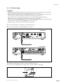
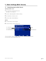
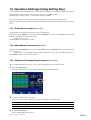
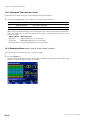
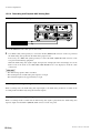
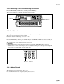
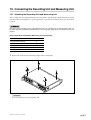
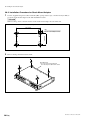
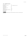
1
Hi-speed HDD Data Recorder
SIR-3400H
Precision Analog Unit / Wide Band Analog Unit
SIR-3032i / SIR-3032W
Read all the instructions in the manual carefully before use and strictly follow them.
Keep the manual for future references.
Instruction Manual
[For U.S.A. and Canada]
[For EU and EFTA countries]
THIS CLASS A DIGITAL DEVICE COMPLIES WITH
PART15 OF THE FCC RULES AND THE CANADIAN
ICES-003. OPERATION IS SUBJECT TO THE
FOLLOWING TWO CONDITIONS.
(1) THIS DEVICE MAY NOT CAUSE HARMFUL
INTERFERENCE, AND
(2) T H I S D E V I C E M U S T A C C E P T A N Y
INTERFERENCE RECEIVED, INCLUDING
INTERFERENCE THAT MAY CAUSE
UNDERSIGNED OPERATION.
CE Notice
Marking by the symbol CE indicates compliance with
the EMC directive and the Low-voltage directive of the
European Community. This marking shows
conformity to the following technical standards.
EN 55011 Group 1 Class A/1998 A1/1999 A2/2002 :
"Limits and methods of measurement of radio
disturbance characteristics of industrial, scientific and
medical (ISM) radio-frequency equipment"
EN 61000-3-2/2000 :
CET APPAREIL NUMÉRIQUE DE LA CLASSE A
EST CONFORME À LA NORME NMB-003 DU
CANADA.
[For the customers in Australia]
Australian EMC Notice
This product complies with the following Australian
EMC standard.
AS/NZS CISPR11/2002 Emission Standard for
ISM Equipment
"Limits for harmonic currents emissions (equipment
input current ≦ 16 A per phase)"
EN 61000-3-3/1995 A1/2001 :
"Limitation of voltage fluctuations and flicker in lowvoltage supply systems for equipment with rated
current ≦ 16 A"
EN 61000-6-2/2001 :
"Electromagnetic compatibility (EMC) - Part 6-2 :
Generic standards - Immunity for industrial
environments"
EN 61010-1/2001 :
"Safety requirements for electrical equipment for
measurement, control and laboratory use Part 1:
General requirements"
For DC power-driven products to meet EN 61000-6-2/2001,
the following operational conditions must be satisfied.
1. Input and output signal cable length : 30 m or less
2. Cable length for input power source : 10 m or less
Note
When using the same cable for output signal and input
power source, the cable must not be longer than 10 m.
For AC power-driven products to meet EN 61000-6-2/2001,
the following operational conditions must be satisfied.
1. Input and output signal cable length : 30 m or less
SIR-3400H / SIR-3032i / SIR-3032W
Raadpleeg uw leverancier indien de
batterij toch vervangen moet worden.
De batterij mag alleen vervangen
worden door vakbekwaam servicepersoneel.
English
Disposal of Waste Electrical and Electronic Equipment for Business use
(Applicable in the European Union and other European countries with separate
collection systems)
This symbol on the product or on its packaging indicates that this product shall not be treated
as household waste. Instead it shall be handed over to the applicable take-back scheme for the
recycling of electrical and electronic equipment. By ensuring this product is disposed of
correctly, you will help prevent potential negative consequences for the environment and
human health, which could otherwise be caused by inappropriate waste handling of this
product. The recycling of materials will help to conserve natural resources. For more detailed
information about recycling of this product, please visit Sony Manufacturing Systems
Europe’s web site:
http://www.sonymanufacturing.com/environment
Deutsch
Entsorgung von als Industriemüll anfallenden elektrischen und elektronischen
Geräten (anzuwenden in den Ländern der Europäischen Union und anderen
europäischen Ländern mit einen separaten Sammelsystem für diese Geräte)
Das Symbol auf dem Produkt oder seiner Verpackung weist darauf hin, dass dieses Produkt
nicht als normaler Haushaltsabfall zu behandeln ist, sondern im Rahmen des entsprechenden
Rücknahmeprogramms für das Recycling von elektrischen Geräten abgegeben werden muss.
Durch Ihren Beitrag zum korrekten Entsorgen dieses Produkts schützen Sie die Umwelt und
die Gesundheit Ihrer Mitmenschen. Umwelt und Gesundheit werden durch falsches Entsorgen
gefährdet. Materialrecycling hilft, den Verbrauch von Rohstoffen zu verringern. Weitere
Informationen über das Recycling dieses Produkts erhalten Sie auf der Webseite von Sony
Manufacturing Systems Europe:
http://www.sonymanufacturing.com/environment
SIR-3400H / SIR-3032i / SIR-3032W
SIR-3400H / SIR-3032i / SIR-3032W
Safety Precautions
Sony Manufacturing Systems Corporation products are designed in full consideration of safety.
However, improper handling during operation or installation is dangerous and may lead to fire,
electric shock or other accidents resulting in serious injury or death. In addition, these actions
may also worsen machine performance.
Therefore, be sure to observe the following safety precautions in order to prevent these types of
accidents, and to read these “Safety Precautions” before operating, installing, maintaining, inspecting, repairing or otherwise working on this unit.
Warning indication meanings
The following indications are used throughout this manual, and their contents should be understood before reading the text.
Warning
Failure to observe these precautions may lead to fire, electric shock or other accidents resulting
in serious injury or death.
Caution
Failure to observe these precautions may lead to electric shock or other accidents resulting in
injury or damage to surrounding objects.
Important
If there is any abnormal phenomena during installation or operation, disconnect the power cord
and contact service engineer person immediately. It is dangerous to use the unit if it is not
operating normally.
General
.
.
.
.
WARNING
No user-serviceable parts are inside the unit. Removing the covers may expose you danger.
Never push objects of any kind into the unit through the slots.
Do not place any liquids on the top of the unit.
Should any object or liquid fall into the unit, turn the power OFF and unplug the unit and call service engineer person to
check it before using again.
The SIR-3000 series should be used indoors or under similar conditions.
Clean the recorder by wiping it with a dry cloth.
.
.
. Be careful that you do not listen to earphones (sold separately) at a high volume for extended periods of time.
SIR-3400H / SIR-3032i / SIR-3032W
(E) (1)
Installation
WARNING
. When unpacking, packing or installing, assign more than 2 persons to handle the unit to prevent injury.
. Be careful never to drop the unit when handling, unboxed or boxed. If the unit is dropped, turn the power
OFF and unplug the unit and call service engineer person to check it before using again.
. Be sure that the unit is firmly positioned on its supporting surface. The unit cause an injury if it falls or
dropped.
. To allow adequate air circulation, do not block the ventilation of the unit.
. Do not place the unit or other heavy objects on the power cord. If damaged, the cord may cause fire or
electric shock.
Operating Cautions
* Be sure to observe the following cautions.
. Use the supplied power cord.
The POWER cord contains a safety earth ground. Make
sure to connect this earth ground. Failure to do so may
result in electric shock or fire.
Make sure to ground
the POWER cable firmly.
Earth
.
.
.
.
.
.
.
CAUTION
Keep the unit away from strong magnetic fields such as high voltage transformers, speakers, and
electric motors.
When receives strong outer noises, the unit may operate improperly.
Do not locate the unit in a dusty, hot or humid place.
Do not place heavy objects on the top of the unit, otherwise it may fall and cause an injury.
To disconnect the power cord or signal cable, always pull it by the plug. Pulling wire may cause it to be
damaged resulting fire or electric shock.
Keep the power cord or signal cable away from where people might step on it or trip over it.
Be sure that the attached AC power cord is firmly connected.
There is a protective ground wire in attached AC power cord.
Operation
WARNING
. Be sure operate the unit only with the specified power supply. Use of an incorrect voltage will
cause severe damage.
. Be sure to input to the unit only the specified signal voltage.
. Replace only with specified type and rated fuse.
CAUTION
. Disconnect the power cord from the unit if it is not in use.
. Disconnect the power cord before replaceing fuse.
(2) (E)
SIR-3400H / SIR-3032i / SIR-3032W
Caution
Please read carefully the following precautions prior to use. These precautions will
prevent your data on recording media from being damaged or lost.
Condensation
In the default settings, the condensation sensor on this unit is set to off.
(1) Always turn the condensation sensor on under conditions where condensation may form easily such as
when the temperature around the recording unit goes from a low to high temperature.
(2) To prevent damage to data in environments where condensation tends to occur, be sure to always eject
the recording media after using the recording unit, and then press the POWER switch to turn off the
power.
<Reference> (Section 7-2-2)
Off : Condensation is not detected. If condensation occurs the recording media and data may become damaged.
On : Condensation is detected when the unit’s power is turned on to protect the recording media and data
from being damaged.
Warming Up/Cooling Down
When the temperature inside the unit is too high or too low, the unit displays one of the following messages
and the unit is automatically cooled down or warming up. The unit cannot be operated until the temperature
reaches proper level and the message on LCD display disappears.
LCD message
Recording unit status
Remarks
Low Temp Warming Up
Internal temperature < 5 dC
Displayed until the internal temperature is
5 dC or higher
Displayed until the internal temperature is less
than 70 dC
High Temp Cooling Down 70 dC < Internal temperature
Overwrite
Once overwritten, the previously recorded data after the point where the overwriting ends cannot be reproduced
(see section 2-5).
<Reference> (Section 8-2-3)
Overwriting is prohibited in the default settings.
To cancel the overwrite protection, set the Overwrite option under Utility_Global Setup Menu_Function to
On in the LCD screen.
In an attempt of overwriting, a message “Overwrite?” will appear on the LCD of the recording unit. If you
wish to overwrite the old data, press FWD key with REC key pressed down.
Power Switch
When turning off the unit completely, first confirm that the ACCESS lamp is out and then turn off the
POWER switch on the rear of unit.
SIR-3400H / SIR-3032i / SIR-3032W
(E) (3)
Caution
Power Supply Back-up (Power Outages or Power Cord Disconnection)
When the power supply is stopped, the unit switches to the backup power supply without turning off the
power. The unit automatically switches to the power supply in the following order of priority (starting from
the highest priority): AC > DC > Internal backup battery.
(1) When the unit is backed up by the internal battery for 3 minutes or longer, to protect the recording
media, the operation is stopped. Then, the unit starts the shut-down operation.
(2) The backup power supply may not be activated if the internal backup battery is not fully charged.
c
The unit is shut-down in the following process of operation in which case both of more than 3 minutes
passed or pressing the Standby key on the front panel to more than 2 seconds, during the back-up operating
state.
The screen display goes out.
(10 seconds at the maximum)
The standby lamp and other lamps on the
front panel go out.
(The unit is completely shut down.)
Connection of Cables for IEPE Inputs
Be sure to make the input format settings while a signal source is not connected to the INPUT connector of
the unit.
Use of IEPE inputs format * may damage the signal source as 24 V power is supplied to the INPUT connector.
* IEPE input format: The input format for using a sensor with built-in the pre-amplifier (IEPE type). In this unit, either TEDS
mode, which acquires the TEDS data, or IEPE mode, which doesn’t acquire TEDS data, can be
selected.
(4) (E)
SIR-3400H / SIR-3032i / SIR-3032W
Contents
1. Overview ......................................................................... 1-1
1-1.
1-2.
Introduction .................................................................................................. 1-1
Major Features ............................................................................................. 1-1
2. Data Format and Basic Operations .............................. 2-1
2-1.
2-2.
2-3.
2-4.
2-5.
2-6.
Data Format .................................................................................................. 2-1
TOC .............................................................................................................. 2-2
Initialization of Recording Media (Formatting) ........................................... 2-2
Removing Recording Media ........................................................................ 2-2
Overwriting Data .......................................................................................... 2-2
ID Block ....................................................................................................... 2-3
3. Names and Functions of Parts ..................................... 3-1
3-1.
3-2.
SIR-3400H (Recording unit) ........................................................................ 3-1
3-1-1. Front Panel .................................................................................. 3-1
3-1-2. Rear Panel ................................................................................. 3-11
3-1-3. Side Panels ................................................................................ 3-15
SIR-3032i/W (Measuring Unit) ................................................................. 3-16
3-2-1. Front Panel ................................................................................ 3-16
3-2-2. Rear Panel ................................................................................. 3-19
3-2-3. Side Panels ................................................................................ 3-21
4. Preparations ................................................................... 4-1
4-1.
4-2.
4-3.
4-4.
4-5.
4-6.
4-7.
Connecting the Power Supply ...................................................................... 4-1
4-1-1. AC Power Supply ........................................................................ 4-1
4-1-2. DC Power Supply ........................................................................ 4-3
4-1-3. Internal Backup Battery .............................................................. 4-4
Connecting the Signals ................................................................................. 4-4
Cartridges ..................................................................................................... 4-5
4-3-1. Cartridges .................................................................................... 4-5
4-3-2. Loading a Cartridge ..................................................................... 4-5
4-3-3. Ejecting the Cartridge ................................................................. 4-6
Diagnostics ................................................................................................... 4-7
Calibration .................................................................................................... 4-7
Required Settings Before Recording ............................................................ 4-7
Source and Record ....................................................................................... 4-8
4-7-1. Source .......................................................................................... 4-8
4-7-2. Record ......................................................................................... 4-8
5. Description of Transport Mode ..................................... 5-1
5-1.
5-2.
5-3.
Transport Modes .......................................................................................... 5-1
Operation Transition Diagram ...................................................................... 5-2
Transport Mode Transition Table ................................................................. 5-3
6. Setting and Check Items................................................ 6-1
6-1.
6-2.
SIR-3400H / SIR-3032i / SIR-3032W
Default Settings ............................................................................................ 6-1
6-1-1. Recording Unit Setting/Checking (Including Media Settings) ... 6-1
6-1-2. Measuring Unit Setting/Checking
(Including Input/Output Settings) ............................................... 6-2
LCD Screen Configuration ........................................................................... 6-3
(E) i
7. Basic Settings (Main Screen) ........................................ 7-1
7-1.
7-2.
Setting Procedure (for Main Screen) ............................................................ 7-1
Settings ......................................................................................................... 7-2
7-2-1. Fan Control On/Off (Fan Control) .............................................. 7-2
7-2-2. Condensation Sensor On/Off (Dew Sense) ................................. 7-2
7-2-3. Synchronized Master/Subordinate Operation (Sync-Mode) ....... 7-3
8. Function Setup (Function Screen) ............................... 8-1
8-1.
8-2.
Setting Procedure (for Function Screen) ...................................................... 8-1
Settings ......................................................................................................... 8-2
8-2-1. Selecting the Frequency Type (Freq-Type) ................................. 8-2
8-2-2. Recording Media Auto Repeat On/Off (Auto-Repeat) ............... 8-2
8-2-3. Recording Media Overwrite On/Off (Overwrite) ....................... 8-2
8-2-4. Selecting the Trigger Mode (Trigger Mode) ............................... 8-3
8-2-5. Pre-Trigger Recording On/Off (Pre-Trigger) .............................. 8-3
8-2-6. IRIG-B Timecode On/Off (IRIG) ............................................... 8-3
9. Display Settings (Display Screen) ................................ 9-1
9-1.
9-2.
Setting Procedure (for Display Screen) ........................................................ 9-1
Settings ......................................................................................................... 9-1
9-2-1. Switching the Response Characteristics (Bar meter Peak) ......... 9-1
9-2-2. Switching the Bar Meter Scale (Bar meter Scale) ...................... 9-2
9-2-3. Adjusting LCD Contrast (LCD Contrast) ................................... 9-2
9-2-4. Adjusting LCD Brightness (LCD Brightness) ............................ 9-2
10. Network Settings (Network Screen) ........................... 10-1
10-1. Setting Procedure ....................................................................................... 10-1
11. Clock Setting (Clock Screen) ...................................... 11-1
11-1. Setting Procedure ....................................................................................... 11-1
12. Operation Settings (Using Setting Key) ..................... 12-1
12-1.
12-2.
12-3.
12-4.
12-5.
ID Number Increments ............................................................................... 12-1
Index Number Increments .......................................................................... 12-1
Setting the Recording/Playback Speed ...................................................... 12-1
Setting the Number of Recording Channels ............................................... 12-2
Setting the Input Range .............................................................................. 12-3
12-5-1. Setting the Manual Range ......................................................... 12-3
12-5-2. Setting the Auto Range .............................................................. 12-4
12-6. Setting the Input DC Offset ........................................................................ 12-5
12-6-1. Setting Input DC Offset Manually ............................................ 12-5
12-6-2. Setting Input DC Offset Automatically ..................................... 12-6
12-7. Setting the Input Format ............................................................................. 12-7
12-8. Setting the Transmission Format ................................................................ 12-8
12-9. Recording Memo ........................................................................................ 12-8
12-10. Setting the Output Level .......................................................................... 12-10
12-11. Setting the Test Signal .............................................................................. 12-11
12-12. Mark Settings ........................................................................................... 12-11
12-13. Panel Lock ................................................................................................ 12-11
ii (E)
SIR-3400H / SIR-3032i / SIR-3032W
13. Other Settings .............................................................. 13-1
13-1. Changing to the Address, Amount of Recording Media Remaining,
or Time Display .......................................................................................... 13-1
13-2. Clearing the Peak Indicator and Over Indicator ......................................... 13-1
13-3. Switching the Speaker or Earphone Playback Signal Source .................... 13-1
13-4. Adjusting the Playback Volume ................................................................. 13-1
13-5. Changing the AC Voltage ........................................................................... 13-2
14. Execution of Function/Checking ................................ 14-1
14-1.
14-2.
14-3.
14-4.
14-5.
14-6.
14-7.
14-8.
Save of Setting Values/Recall of Setting Values (Save/Recall Setup) ........ 14-1
Copying Mark1/Mark2 (Copy) .................................................................. 14-3
Formatting the Hard Disk Drive (Format) ................................................. 14-4
Repairing Recording Media Discrepancies (RAID Rebuild) ..................... 14-5
Executing Calibration (Calibration) ........................................................... 14-6
Bar Meter Auto Adjustment (Barmeter Auto Adjustment) ........................ 14-7
Executing Diagnostics (Diagnostics) ......................................................... 14-8
Checking the Recording Media Contents (TOC Viewer) ........................... 14-9
14-8-1. Viewing the TOC List ............................................................... 14-9
14-8-2. Detailed INDEX List including IDs .......................................... 14-9
14-8-3. TOC Screen Elements ............................................................. 14-10
15. Data Recording/Playback ............................................ 15-1
15-1. Data Recording ........................................................................................... 15-1
15-2. Data Playback ............................................................................................. 15-3
15-3. Recording and Playback Voice Annotations .............................................. 15-4
15-3-1. Connecting the Microphone and Earphone ............................... 15-4
15-3-2. Recording Voice Annotations .................................................... 15-5
15-3-3. Playback Voice Annotations ...................................................... 15-5
15-4. Recording and Playback AUX Digital Data ............................................... 15-6
15-4-1. Connecting the AUX Digital Data ............................................. 15-7
15-4-2. Recording AUX Digital Data Signals ....................................... 15-7
15-4-3. Playback AUX Digital Data Signals ......................................... 15-7
15-5. Recording and Playback AUX Analog Data .............................................. 15-8
15-5-1. Recording and Playback IRIG-B Time Code Signal ................. 15-8
15-5-2. Recording and Playback AUX Analog Data ........................... 15-10
15-6. Trigger Recording .................................................................................... 15-11
15-6-1. Connecting the Trigger Signal ................................................ 15-11
15-6-2. Trigger Recording ................................................................... 15-12
15-6-3. Playback of the Pre-trigger Data ............................................. 15-12
16. Search ........................................................................... 16-1
16-1. ID/INDEX Number Search ........................................................................ 16-2
16-1-1. Searching with the SEARCH key ............................................. 16-2
16-1-2. Searching with the TOC Viewer ................................................ 16-2
16-2. Start ID Search ........................................................................................... 16-2
16-2-1. Searching at the Next Recording Start Position ........................ 16-2
16-2-2. Searching at the Current Recording Start Position ................... 16-3
16-3. Mark Search ............................................................................................... 16-3
16-4. Address Search ........................................................................................... 16-3
SIR-3400H / SIR-3032i / SIR-3032W
(E) iii
16-5. Real-time Clock Search .............................................................................. 16-4
16-6. Manual Search ............................................................................................ 16-4
17. Control by Telnet .......................................................... 17-1
17-1. Command Overview .................................................................................. 17-2
17-2. Command Details ....................................................................................... 17-4
18. Errors and Error Messages ......................................... 18-1
18-1. Warning Messages ...................................................................................... 18-1
18-2. Error Code .................................................................................................. 18-2
18-3. Remedies for Operation Errors .................................................................. 18-3
18-3-1. When Power does not Turn On when Standby Switch is Held
Down for Two Seconds, or Key Operation is Disabled ............ 18-3
19. Connecting the Recording Unit
and Measuring Unit ...................................................... 19-1
19-1. Attaching the Recording Unit and Measuring Unit ................................... 19-1
19-2. Cable Connections ..................................................................................... 19-3
20. Installing the Shock Mount Adaptor ........................... 20-1
20-1. Before Usage .............................................................................................. 20-1
20-2. Installation Procedure for Shock Mount Adaptor ...................................... 20-2
21. Attaching the Rack Mount Adaptor ............................ 21-1
21-1. Before Use .................................................................................................. 21-1
21-2. Attachment Procedure for Rack Mount Adaptor ....................................... 21-1
22. Specifications ............................................................... 22-1
22-1. Specifications (SIR-3400H) ....................................................................... 22-1
22-1-1. Cartridges .................................................................................. 22-1
22-1-2. Voice Annotation Channel ......................................................... 22-1
22-1-3. Monitor Out ............................................................................... 22-1
22-1-4. AUX Digital Channel (AUX-1) ................................................ 22-1
22-1-5. AUX Analog Channel (AUX-2, IRIG-B Channel) ................... 22-2
22-1-6. Power Supply System ................................................................ 22-2
22-1-7. External Dimensions/Mass ........................................................ 22-2
22-1-8. Operating Environment ............................................................. 22-3
22-1-9. Supplied Accessories ................................................................. 22-3
22-2. Specifications (SIR-3032i/W) .................................................................... 22-4
22-2-1. Recording/Playback System ...................................................... 22-4
22-2-2. Operation System ...................................................................... 22-5
22-2-3. Monitor System ......................................................................... 22-5
22-2-4. Power Supply System ................................................................ 22-6
22-2-5. Dimensions and Mass ............................................................... 22-6
22-2-6. Operating Environment ............................................................. 22-6
22-2-7. Supplied Accessories ................................................................. 22-7
iv (E)
SIR-3400H / SIR-3032i / SIR-3032W
1. Overview
1-1. Introduction
The SIR-3000 series is a lineup of data recorders consisting of a recording unit and measuring unit. The
recording unit and measuring unit are used in combination together.
Seven speeds are available for both recording and playback so that high-speed data recorded at 4x speed can
be played back at 1/16x speed, or the maximum 250 hours of data recorded at 1/16x speed can be played in
four hours at 4x speed.
SIR-3400H (recording unit)
This device records data obtained from the measuring unit.
Two hard disk drives (HDD) are used for the recording media. Data is written simultaneously to the two
HDDs so that even if a failure were to occur in one HDD, recording is still maintained in the other HDD.
When the SMH-200 is used, the capacity of HDD is 200 Gbytes. The unit can continuously record the digital
data of 128 ch x 20 kHz (SIR-3032i / SIR-3032W) / 32 ch x 80 kHz (SIR-3032W) for about 4 hours.
SIR-3032i/SIR-3032W (measuring unit)
This device sends the measured data to the recording unit.
Up to four measuring units can be connected to a single recording unit.
1-2. Major Features
Wideband, Multi-Channel
By combining with a measuring unit, the SIR-3000 series can be used to build the optimum system for
measurement subjects.
Support for 32 ch x 20 kHz is provided by combining the minimum configuration of the SIR-3400H and
SIR-3032i.
Replacing the measuring unit with the SIR-3032W enables wideband recording at 32 ch x 80 kHz.
Connection of four SIR-3032i/W to the recording unit enables recording and playback to one HDD group at
128 ch x 20 kHz.
Equipped with Sensor Input
The SIR-3032i/W (measuring unit) can supply power to the sensor with built-in pre-amplifier (IEPE type).
This enables the sensor to be connected directly to the data recorder, realizing enhanced portability and
saving total costs. A choice between the IEPE input (IEPE or TEDS) and conventional DIRECT input is
available for each channel.
Input Range
The input range now covers ± 0.1 Vpk to ± 10 Vpk (Maximum 7 ranges), enabling a broad range of signals to
be recorded and played back at the optimum levels.
Subchannels
In addition to the above analog channels, the recorder is equipped with the subchannels listed below to allow
various types of subdata to be recorded or played back together with the analog data.
Channel
Application
Input/Output connector
Voice channel
Voice annotation
Front panel
AUX analog channel
IRIG-B timecodes, etc.
Rear panel
AUX digital channel
Binary data such as tacho pulse
Rear panel
SIR-3400H / SIR-3032i / SIR-3032W
(E) 1-1
1. Overview
Recording/Playback
By adopting the 16 bit linear quantization, the dynamic range of 90 dB Typ is achieved. Further more the
phase difference between channels is suppressed to less than 1 degree. And the analog input level is allowed
to ± 133 % of the input range value, and the input DC offset of each channel can be automatically or manually
adjusted within ± 100 %.
Time Axis Conversion
Data speeds for recording and playback can be selected from the 7 levels of 4, 2, 1 (normal speed), 1/2, 1/4,
1/8 and 1/16. Data can be recorded for a maximum of 256 hours at 1/16 speed when using a 200 GB HDD.
By playing back at low speed the data recorded at high speed, data can be converted to the playback frequency
to meet the process speed of the external analyzing equipment.
Synchronized Operation
By connecting two recording units with the synchronizing cable (option), the synchronized recording/playback
can be performed with accuracy of a quartz level.
This enables doubling of the number of channels without reducing the frequency bandwidth or data transfer
rate.
Trigger Recording
Recording can be started by receiving the trigger signal from the external source.
Once the pre-trigger is enabled, a built-in large capacity data buffer memory allows data to be recorded
before and after a trigger. This is useful for recording suddenly-occurring phenomena such as lightning and
avalanches.
Compatibility with Computers
Data recorded in HDDs by the SIR-3000 series can be read out directly using the optional Media docking
station (STC-3010).
Therefore, even if the recording unit is not available, data can be directly analyzed.
High-speed Data Transfer Interface
By employing the high-speed data transfer interface (option), digital data can be transferred to a computer in
real-time during recording or playing back. (The transfer speed depends on the computer performance.)
Control Functions
The unit can be controlled from the local (front panel) or from the host computer via Ethernet.
1-2 (E)
SIR-3400H / SIR-3032i / SIR-3032W
1. Overview
2-way Power Supply System
The SIR-3000 series can run on AC 100/120 V (allowable range 90 to 132 V) or AC 220/240 V (allowable
range 198 to 250 V), or DC 12 V (allowable range 11 to 30 V) supplied externally. The recording unit also
includes a dedicated nickel-hydride battery pack for smooth, uninterrupted operation if the power is suddenly
cut off.
The unit automatically switches to the power supply in the following order of priority: 1 AC, 2 DC, 3
internal backup battery.
If the AC source is cut off, the external DC or internal backup battery provides uninterrupted backup. If the
external DC source is cut off, the internal backup battery provides uninterrupted backup. The SIR-3000
series cannot operate on the battery only. The internal backup battery is used to protect the recording media
when the power failure occurs. When the backup operation continues for 3 minutes or longer, the unit is shut
down.
n
The internal backup battery is recharged automatically, but note that it may not be charged in the cases
shown below based on the power switch setting or power supply conditions.
Power switch
off
Power switch on
No power
Standby mode
supply input
DC
AC + DC
AC
Operating
mode
Internal backup
battery charging
No
No
Yes
Yes
Yes
Yes
Standby lamp
Off
Off
Lit orange
Lit orange
Lit orange
Lit green
Easy Operation
The SIR-3000 series was designed to provide an intuitive man-machine interface.
. Central display screen featuring a backlit, semi-transparent, color LCD panel.
. Direct access to all functions by dedicated keys.
Compact and Light
Dimensions of 449 (W) x 88 (H) x 305 (D) mm (recording unit only, without projections) and a weight of
approximately 10.5 kg for the recording unit and 7.5 kg for the measuring unit give the SIR-3000 a design
with superior compactness and portability.
SIR-3400H / SIR-3032i / SIR-3032W
(E) 1-3
1-4 (E)
SIR-3400H / SIR-3032i / SIR-3032W
2. Data Format and Basic Operations
2-1. Data Format
Data recorded to HDDs by the SIR-3400H is based on the FAT32 logical format. However, at the application
level the data is of the SIR dedicated format. This is outlined below.
Generally, recording and playback are performed by observing the HDD as sequential media.
Start of recording
Start ID
Start ID
ID001
BOM
BOD
ID002
ID003
ID number increments
ID004
ID999
T
O
C
TOC
EOD
Blank
EOM
. SHIFT + INDEX/ID key
. When the INDEX number exceeds 99
INDEX01
INDEX99
INDEX number increment
. INDEX/ID key
BOM (Beginning Of Media)
Position of beginning physical recording.
BOD (Beginning Of Data)
User data is recorded from here.
EOD (End Of Data)
Each time recording stops, an EOD is written.
When a recording is added, the previous EOD is overwritten and
deleted, and a new EOD is written at the location where the last
recording ended. Generally, data cannot be read after the EOD, even
if previously recorded data remains.
EOM (End Of Media)
Last position where recording is physically possible.
ID number
ID blocks are formed for each recording with ID numbers (001 to 999)
automatically assigned. These can be used for ID searches.
Increments
-Automatic. Start of each recording (including cancellation of recording
pauses)
. When the index number exceeds 99
-Manual. When the INDEX/ID key is pressed after the SHIFT key during
recording
INDEX number
An index (01 to 99) can be added at desired locations during
measuring. By marking an index, the desired location can quickly be
found during analysis (INDEX search).
Increments
-Manual. When the INDEX/ID key is pressed during recording
Start ID
This indicates the point where recording starts. The start ID is not actually
written on the recording media, but the position is registered in the TOC.
The start ID can be used for start ID searches.
TOC (Table of Contents)
The position and other information for all ID blocks are recorded in table
format in this area.
SIR-3400H / SIR-3032i / SIR-3032W
(E) 2-1
2. Data Format and Basic Operations
2-2. TOC
The position on the media of each recording block is registered in the TOC together with the ID and index
number and recorded immediately before the EOD. This allows searching to be performed by specifying an
ID or index number.
2-3. Initialization of Recording Media (Formatting)
When a different format (such as one where data has been written by a computer) or unformatted SMH
cartridge is loaded in the SIR-3400H, the Format Error is displayed on the LCD screen. Implement the HDD
formatting.
2-4. Removing Recording Media
Before removing a HDD, be sure to first set to STOP mode and check that HDD access has been completed.
Then, use the supplied key to eject the cartridge. If you attempt to remove it during HDD access, the HDD
can be damaged. Remove the cartridge after making sure that the access lamp goes out.
If you open the front panel while in REC mode, a warning sound is made continuously to indicate that
recording is in progress.
2-5. Overwriting Data
Overwriting can be performed on pre-recorded HDDs. An EOD is written at the point where the new recording
ends, and so old data remaining after that point cannot be played back. Therefore, care should be taken when
overwriting on pre-recorded HDDs. The figure below shows an example of an HDD which has been
overwritten from the middle of ID number 003.
Start ID
Start ID
ID001
ID002
ID003
ID004
ID100
BOM BOD
T
O
C
Blank
EOM
EOD
Status before overwriting (example)
New recording start
ID001
ID002
ID003
ID004
Not played back
T
O
C
Recording stop
BOM BOD
Blank
EOD
EOM
Status after overwriting on the data in ID003 (example)
New recording start
Not played back
T
ID001 O
C
BOM BOD
Blank
EOD
EOM
Status after overwriting from the BOD (example)
2-2 (E)
SIR-3400H / SIR-3032i / SIR-3032W
2. Data Format and Basic Operations
2-6. ID Block
Each ID block consists of segments of approximately 550 kbytes referred to Records. Therefore, the shortest
ID block length is one Record. This is approximately 42 ms at 4x speed, 170 ms at normal speed (1x), and
2.7 seconds at 1/16x speed. Thus, recording at 1/16x speed cannot be stopped within 2.7 seconds.
SIR-3400H / SIR-3032i / SIR-3032W
(E) 2-3
2-4 (E)
SIR-3400H / SIR-3032i / SIR-3032W
3. Names and Functions of Parts
3-1. SIR-3400H (Recording unit)
3-1-1. Front Panel
1 Standby key
2 Front panel lock knobs
3 Ventilation slits
LCD screen
Announcement
monitor area
Setting keys
Transport
operation keys
1 Standby key
Used to changes mode between standby and operation. Press and keeping this key at least two seconds
to changes standby or operation mode.
* When the unit is set to the panel lock mode, the standby key is also inhibited.
Power switch
off
Power switch on
No power
Standby mode
supply input
DC
AC + DC
AC
Operation
mode
Standby key
Disabled
Disabled
Hold down for 2 seconds to switch between
standby and operation modes
Standby lamp
Off
Off
Lit orange
Lit orange
Lit orange
Lit green
2 Front panel lock knobs
Used to open and close the front panel.
When set to RELEASE, the front panel can be opened. When the front panel is closed, both knobs are
set to LOCK.
c
Be sure to always close the front panel when using the recording unit.
3 Ventilation slits
These slits are used to take in air to cool the inside of the recording unit.
To prevent the inside of the recording unit from overheating, do not cover the ventilation slits.
SIR-3400H / SIR-3032i / SIR-3032W
(E) 3-1
3. Names and Functions of Parts
Transport Operations Keys
The lamps above the keys light to indicate the active mode.
During transport mode transition, the lamp over the respective key blinks, and no key operation is accepted.
4
6
7
5
9
0
qa
qs
8
4 ACCESS lamps (1, 2)
Lights when access to the recording media is possible.
The lamps blink while access is in progress.
ACCESS1: Recording media 1
ACCESS2: Recording media 2
Lit green
Access possible
Blinking orange
HDD operation in progress
5 BOD lamp
Lights when the recording media is at the BOD (beginning of data recorded on the recording media)
position.
6 REW key
Used for the following operations.
. Rewinding data
. Start ID search of the current data
. Manual search (rewind direction)
7 FF key
Used for the following operations.
. Fast-forwarding data
. Start ID search of the next data
. Manual search (fast-forward direction)
8 EOD lamp
Lights when the recording media is at the EOD (end of data recorded on the recording media) position.
9 FWD key
Plays back the data.
0 STOP key
Stops data playback or recording.
c
After the stop key is pressed, a buffer recording for up to 20 seconds is made. As a result, the recording
media may not stop.
qa REC key
Press this key alone to select the E-E mode.
Press this key together with the FWD key to record data.
qs PAUSE key
Used when performing a recording pause or playback pause.
3-2 (E)
SIR-3400H / SIR-3032i / SIR-3032W
3. Names and Functions of Parts
LCD Screen
Checking of the recording and playback statuses, basic settings, operation settings, and other operations are
performed at the LCD screen.
For details about the settings, see the setting description chapter. This section explains the recording/playback
screen (Measurement).
qd
qg
qh
qj
qf
qk
ql
w;
wa
ws
wd
wf
qd Title display area
This area displays the title of the currently displayed screen.
For details, see “6-2. LCD Screen Configuration.”
qf Status display area
This area uses icons to indicate the input status of subchannel data or essential notification information
such as errors or warnings.
Mark
Description
When a power supply error occurs
When a condensation error occurs
When a recording/playback error occurs
When multiple measuring units are operating in synchronizing mode
When signals are input to the AUX1 (DIGITAL) IN connector or when the recorded
signals are played back
When signals are input to the AUX2 (IRIG-B) IN connector or when the recorded
signals are played back
When IRIG-B time code signals that are input from an external time code generator
are detected correctly or when the recorded signals are played back
When the playback signal source of the speakers or earphones are set to voice
annotation
When the playback signal source of the speakers or earphones are set to analog
data signals
SIR-3400H / SIR-3032i / SIR-3032W
(E) 3-3
3. Names and Functions of Parts
qg Bar meter display area
This area displays the bar meters for each channel.
A single bar meter indicates one channel. A maximum of 16 channels can be displayed from left to right.
The displayed channels vary depending on if the red frame is lit for A or B in the measuring unit number
display area w;.
A: Channels 1 to 16
B: Channels 17 to 32
Selection of a bidirectional or unidirectional bar meter is made using the Barmeter Scale setting (section
9-2-2).
qh ID display area
This area indicates the ID number.
The displayed information varies depending on the transport mode.
Transport mode
Display
E-E, REC-PAUSE, REC, and succeeding STOP
Value set in recording unit
FWD and succeeding STOP
Value recorded on recording media
qj INDEX display area
This area indicates the INDEX number.
The displayed information varies depending on the transport mode.
Transport mode
Display
E-E, REC-PAUSE, REC, and succeeding STOP
Value set in recording unit
FWD and succeeding STOP
Value recorded on recording media
qk Speed display area
This are displays the speed of the recording media.
The displayed information varies depending on the transport mode.
Transport mode
Display
E-E, REC-PAUSE, REC, and succeeding STOP
Value set in recording unit
FWD and succeeding STOP
Value recorded on recording media
ql Recording media position display area
The displayed information varies depending on the transport mode.
Transport mode
Display
E-E, REC-PAUSE, REC, and succeeding STOP
ADDRESS, REMAIN, and S-TIME values set in
recording unit
FWD and succeeding STOP
ADDRESS, REMAIN, and R-TIME values
recorded on recording media
ADDRESS : Displays the recording media position from the (00H00M00S) of each recording block in
hour, minute and second.
. The address is set automatically to 00H00M00S when recording begins.
. The address counts in step with real time at 1x speed, and slows down in proportion to
the speed at 1/2 speed or slower.
. In addition, when operating at 1/2 speed or slower, the lower digit for indication of
seconds blinks at a rate of once per second.
REMAIN : Displays the amount of recording media remaining in hour and minute according to the
speed.
S-TIME : Displays the current time in recording unit in year/month/day and in hour/minute/second.
R-TIME : Displays the time recorded on the recording media in year/month/day and in hour/minute/
second.
3-4 (E)
SIR-3400H / SIR-3032i / SIR-3032W
3. Names and Functions of Parts
w; Measuring unit number display area
This area displays the measuring unit number and channel group of the displayed bar meter.
The displayed bar meter channels gorup vary depending on if the red frame is lit for A or B.
A: Channels 1 to 16
B: Channels 17 to 32
wa MONITOR display area
This area displays the channel number selected for monitor output of the recording unit.
ws Setting value display area
This area displays setting values, recording notes, status of the recording unit, and other information
using the setting key.
<Displayed setting values>
Input range, Input DC offset, Output level, Input format, Recording note, Test signal
wd Recording media status display area
This area displays the recording media capacity that is being used.
wf Function key command display area
This area displays the function key commands during setting.
(The function key commands vary depending on the setting option.)
SIR-3400H / SIR-3032i / SIR-3032W
(E) 3-5
3. Names and Functions of Parts
Setting Keys
The setting keys can be used to perform the following two operations.
. Function and operation settings
. Input of numbers and text (for recording notes only)
Key operation is described primary as function/operation keys.
Also, in this manual, the key names (such as INDEX/ID key) are used as function/operation setting keys
except in the description of note recording.
wg
wh
wj
e;
ej
wk
wl
ea
ef
es eg eh ed
ek
The enabled keys are changed in transport mode. (Yes: Enabled, No: Disabled)
Transport
mode
Setting keys
INDEX/ID SPD/BCM SPEAKER
RANGE OFFSET INPUT SEARCH MEMO OUT/TSG MRK1
MRK2
SHIFT
STOP
No
Yes
Yes
Yes
Yes
Yes
Yes
Yes
Yes/No
Yes
Yes
Yes
E-E
No
Yes
Yes
Yes
Yes
No
No
Yes
Yes
Yes
Yes
Yes
REC-PAUSE No
Yes
Yes
Yes
Yes
No
No
Yes
Yes
Yes
Yes
Yes
REC
Yes
No
Yes
Yes
Yes
No
No
Yes
Yes
Yes
Yes
Yes
FWD
No
No
Yes
No
No
No
No
No
Yes/No
Yes
Yes
No
FF
No
No
Yes
No
No
No
No
No
No
No
No
No
REW
No
No
Yes
No
No
No
No
No
No
No
No
No
SEARCH
No
No
No
No
No
No
No
No
No
No
No
No
<Lamps>
The lamp above the key indicates the status below.
Blinking : The key is enabled.
Lit
: The key was pressed, and the setting can be made.
When there are two lamps, the key has the following two functions. (See “Setting Key Descriptions”.)
Left-side lamp : When the key is pressed by itself
Right-side lamp : When the setting key is pressed after pressing the SHIFT key (except for the SHIFT key
right lamp)
<Setting Key Descriptions>
The functions of some setting keys change depending on if the key was pressed by itself or if the setting key
was pressed after pressing the SHIFT key.
The descriptions in this section use the expressions below to indicate how the key was pressed.
When the key is pressed by itself
: No additional comment
When the setting key is pressed after the SHIFT key : in SHIFT mode
3-6 (E)
SIR-3400H / SIR-3032i / SIR-3032W
3. Names and Functions of Parts
wg INDEX/ID key
Press this key to increment the value of the INDEX number by 1 in the REC mode.
INDEX number: 01 to 99 (The ID numbers increase up to 99 and then go back to 01.)
When this key is pressed in SEARCH mode, the data for the set INDEX number is searched.
[In SHIFT mode]
Press this key to increment the value of the ID number by 1 in the REC mode.
ID number: 001 to 999
When this key is pressed in SEARCH mode, the data for the set ID number is searched.
These keys wh to ed are used when making the settings below.
Number
Key
Key by itself
In SHIFT mode
wh
SPD/BCM key
Recording/Playback speed setting
Setting for number of recording
channels
wj
SPEAKER key
Selects the speaker or the
earphone for listening to the
played signal
wk
RANGE key
Manual range setting
Auto range setting
wl
OFFSET key
Manual input DC offset setting
Auto input DC offset setting
e;
INPUT key
Input format setting
ea
SEARCH key
Search mode setting
es
MEMO key
Editing of recording note
ed
OUT/TSG key
Output level setting
Test signal setting
ef MRK1/MRK2 key
Press this key in REC or FWD mode to store the current recording or playback position in the memory.
eg SHIFT key
This key enables the shift operation for each setting key.
Hold the SHIFT key down for at least 2 seconds to switch key operation of the recording unit between
enabled or disabled.
eh PNL LOK lamp
Lights when key operation of the recording unit is set to disable (panel lock mode).
ej f, F, g, G keys
. Used to select items and values.
. Used for changing monitor channels.
f / F key : Every 16 channels
g / G key : Every channel
ek F1 to F4 keys
The functions displayed on the current LCD screen are assigned to F1 to F4 keys. The assigned functions
vary depending on the setting item.
SIR-3400H / SIR-3032i / SIR-3032W
(E) 3-7
3. Names and Functions of Parts
Announcement Monitor Area
el
r;
ra
rs
el VOL knob
Rotate to adjust the playback volume for the speakers or earphones.
r; PHONE jack
Insert the plug of any separately purchased earphones using a mini plug here.
ra MIC jack
Insert the supplied microphone plug here.
The lamp at the bottom right lights according to the sound input.
rs MONITOR
The channel of the measuring unit displayed on the LCD screen is output.
3-8 (E)
SIR-3400H / SIR-3032i / SIR-3032W
3. Names and Functions of Parts
Inside the Front Panel
When the two lock knobs on the front panel are set to RELEASE, the front panel can be opened.
When the front panel is opened, the recording unit cannot switch to REC mode.
c
Do not open the front panel when the hard disk (HDD) is being accessed during recording, playback, or
other operations.
When the front panel is opened during recording or playback, a continuous warning sound is made.
rg
rd
rh
ts
rj
rf
rh
rj
rk
rl
t;
ta
rd HDD1
Stores the recorded data.
rf HDD2
Stores the recorded data. It is a mirror disk of HDD1.
rg HDD keyholes
These are the HDD keyholes. The supplied HDD key is used to lock or unlock the HDD compartments
such as when replacing the hard disks.
Unlocked
Locked
rh HDD power lamp
If the HDD compartment is locked when the power is on, the lamp is lit green. If it is unlocked, the HDD
power is turned off, and the lamp turns off.
rj HDD access lamp
Blinking orange: HDD is being accessed
c
To eject the HDD, first set to STOP mode, and then check that the HDD access lamp is turned off. The
HDD can be damaged if you unlock the HDD while the HDD access lamp is turned on.
SIR-3400H / SIR-3032i / SIR-3032W
(E) 3-9
3. Names and Functions of Parts
rk Speaker
Used to playback the sound of monitor channel or voice channel.
rl HDD key
Used for locking and unlocking the HDD.
t; Recording media error lamps
Lit red when an error occurs in HDDs.
Lamp status
Main error cause
Error recovery method
Blinking
A discrepancy has occurred in the HDD1 and
HDD2 data.
. RAID rebuild
. HDD initialization
. HDD replacement
Lit
An error occurred during HDD access.
. HDD initialization
. HDD replacement
ta Recording media access lamps
Lit green
The recording unit has recognized the recording media.
Blinking orange
The recording unit is accessing the recording media.
ts Option slot
The recording unit settings are stores in a CF-type flash memory. The stored settings are used to make
the various settings of the recording unit.
3-10 (E)
SIR-3400H / SIR-3032i / SIR-3032W
3. Names and Functions of Parts
3-1-2. Rear Panel
1
Aux output /
TRIGER input block
Power supply block
Control block
Option slots
1 Ventilation fans
These fans cool the inside of the recording unit.
. To prevent the inside of the recording unit from overheating, do not block the air outlet.
. Leave a space of at least 100 mm between the rear side of the recording unit and any other
object.
SIR-3400H / SIR-3032i / SIR-3032W
(E) 3-11
3. Names and Functions of Parts
Power Supply Block
2 3
4
5 67
2 AC IN
Used to supply external AC power to the recording unit.
Connect the supplied AC power cord.
3 POWER switch
Used to turn the main power of the recording unit on and off.
w
Be sure to check that the recording unit is in standby mode before turning off the power. If the power is
turned off during HDD operation, the HDD could be damaged.
4 AC voltage selector switch
Used to switch the AC power voltage.
Left side : 100/120 V (allowable 90 to 132 V)
Right side : 220/240 V (allowable 198 to 250 V)
. If using a voltage different from that printed on the sticker shown on the AC voltage selector
switch, peel off the sticker and switch the selector to the side where the voltage is being used.
. The AC power cord has a safety earth. Be sure to connect the power cord to an earthed
socket.
5 DC IN
Used to supply external DC power to the recording unit.
Connect the supplied DC power cord.
Be sure to supply voltage (DC 11 to 30 V) within the specified range.
6 DC fuse
This fuse is used to protect the DC power system.
When the fuse is blown, be sure to use the specified fuse of time-lag type with the following
specifications:
Rated current
10 A
Rated voltage
250 V
Size
5 ø20L
Be sure to disconnect the DC power cord before replacing the fuse.
7 Ground terminal
This is a ground terminal for the frame ground.
3-12 (E)
SIR-3400H / SIR-3032i / SIR-3032W
3. Names and Functions of Parts
Aux Output / TRIGER Input Block
8
9
q;
8 AUX-2 (IRIG-B) IN/OUT
Used to input (IN) and output (OUT) IRIG-B data.
9 AUX-1 (DIGITAL) IN/OUT
Used to input (IN) and output (OUT) AUX digital channel data.
q; TRIG REC IN connector
Used to input the trigger for trigger recording.
Control Block
qd
qf
qs qa
qa ETHER connector
Used to control the recording unit from a remote computer.
qs TO SYNC connector
Used to synchronously operate multiple recording units.
qd TO HOST connector
Used to control the recording unit from a host computer.
qf TO EXPMAIN1/TO EXPMAIN2 connector
Used to connect the measuring units.
SIR-3400H / SIR-3032i / SIR-3032W
(E) 3-13
3. Names and Functions of Parts
Option Slots
qg
qg Option slot
Insert optional boards here.
3-14 (E)
SIR-3400H / SIR-3032i / SIR-3032W
3. Names and Functions of Parts
3-1-3. Side Panels
1
2
Right side panel
Left side panel
2
1
1 Measuring unit connection holes
Used to connect the measuring units.
Used to secure the shock mount adaptor.
2 Ventilation slits
These slits are used to take in air to cool the inside of the recording unit.
. To prevent the inside of the recording unit from overheating, do not block the ventilation
slits.
. Do not place hot objects on the right and left side of the recording unit.
. Leave a space of at least 50 mm between the right and left sides of the recording unit and any
other object.
SIR-3400H / SIR-3032i / SIR-3032W
(E) 3-15
3. Names and Functions of Parts
3-2. SIR-3032i/W (Measuring Unit)
3-2-1. Front Panel
1
2
Analog input connectors
Indicator block
MONITOR
UP
DN
1 Standby lamp
Off
Stopped mode
Lit orange
Standby mode
Lit green
Operating mode
2 Ventilation slits
These slits are used to take in air to cool the inside of the measuring unit.
To prevent the measuring unit from overheating, do not block the ventilation slits.
3-16 (E)
SIR-3400H / SIR-3032i / SIR-3032W
3. Names and Functions of Parts
Analog Input Connectors
The analog input block consists of channel groups of A (top row) and B (bottom row).
Each channel group corresponds to channels below.
A : Channels 1 to 16
B : Channels 17 to 32
The LCD screen bar meters of the recording unit are displayed for A or B of the analog input connectors.
You can check whether the A or B is displayed by viewing the measuring unit number display area of the
recording unit.
4
6
3
5
7
MONITOR
UP
DN
3 Input channel number
Displays the channel of the analog input connectors.
When there are multiple measuring units, the channels are put in order starting from the smallest measuring
unit number.
<Example> Channel assignments for two 32-channel measuring units
Unit 1 : Channels 1 to 32
Unit 2 : Channels 33 to 64
4 IEPE lamp
When the input channel is set to IEPE (IEPE or TEDS), the lamp lights green.
c
Be sure to make the input format setting while a signal source is not connected to the INPUT connector
of the unit.
Use of IEPE inputs * may damage the signal source as 24 V power is supplied to the INPUT connector.
* IEPE input format: The input format for using a sensor with built-in the pre-amplifier (IEPE type). In this unit, either
TEDS mode, which acquires the TEDS data, or IEPE mode, which doesn’t acquire TEDS data,
can be selected.
5 S/D selector switch
Sets the transmission format in the analog input block.
S : Single-ended
D : Differential
SIR-3400H / SIR-3032i / SIR-3032W
(E) 3-17
3. Names and Functions of Parts
6 LVL lamp
Displays the status of the signal input.
Off
No input signal.
Lit green
Signal is input from 5 to 100 %
Lit orange
Signal is input from 100 to 133 %
Lit red
Signal exceeds the range.
7 INPUT connector
Used to input analog signals.
. Be sure to input the specified voltage ± 13.3 Vpk.
. Do not supply input signals exceeding ± 50 Vpk, or the internal circuitry may be damaged.
Monitor Output Block
8
9
MONITOR
0
UP
DN
qa
8 Monitor lamp
Displays the indicator display status.
Lit green : The monitor channel is displayed on the indicator.
Lit orange : The recording unit has selected the measuring unit as the monitor channel while the
monitor channel is displayed on the indicator.
Off
: A measuring unit number (EXP No.) is displayed on the indicator.
9 Indicator
Displays the measuring unit status.
Power on
: Measuring unit number (EXP No.) (3 seconds)
Normal
: Number of channel currently being monitored
EXP No. setting : The 8 monitor lamp is turned off when the measuring unit number (EXP No.) is
displayed.
Error occurred : Error number
0 Setting button
Used to set the monitor channel and measuring unit number (EXP No.).
The number displayed on the indicator is incremented or decremented (UP: Increment, DN: Decrement).
Press the UP button and DN button at the same time to switch to the EXP No. display where the measuring
unit number setting can be made. When connecting several measuring units, set the measuring unit
number starting with “1” and incrementing up by one every time a measuring unit is added.
If the setting button is not pressed within three seconds after the EXP No. display is displayed, it changes
back to the monitor channel display.
qa Monitor output
Outputs the channel number displayed on the indicator from the analog channel output in the measuring
unit.
3-18 (E)
SIR-3400H / SIR-3032i / SIR-3032W
3. Names and Functions of Parts
3-2-2. Rear Panel
Power supply block
1
2
3 Analog output connectors
1 TO EXPMAIN/EXP connector
Used to connect with a recording unit or SIF-3004 (measuring unit expansion board).
2 DIP switches
These switches are used to make measuring unit settings.
SW1 to SW3 : These set the initial EXP No. of the measuring unit.
SW
1
2
3
EXP No.
Maximum number of
effective channels
OFF
OFF
OFF
1
32
ON
OFF
OFF
2
64
OFF
ON
OFF
3
128
ON
ON
OFF
4
128
OFF
OFF
ON
Reserve
Reserve
ON
OFF
ON
Reserve
Reserve
OFF
ON
ON
Reserve
Reserve
ON
ON
ON
Reserve
Reserve
SW4 to SW8 : Disabled
SW8
: This sets the calibration function.
DISABLE: Disables the calibration function.
ENABLE : Enables the calibration function (factory setting).
3 OUTPUT connectors
Used to output analog signals.
Connect BNC cables (sold separately) to the corresponding connectors.
When there are multiple measuring units, the channels are put in order starting from the smallest EXP
No.
<Example> Channel assignments for two 32-channel measuring units
EXP No. 1 : Channels 1 to 32
EXP No. 2 : Channels 33 to 64
SIR-3400H / SIR-3032i / SIR-3032W
(E) 3-19
3. Names and Functions of Parts
Power Supply Block
4
5
6
7
8
9
4 AC IN connector
Used to supply external AC power to the measuring unit.
Connect the supplied AC power cord.
5 POWER switch
Used to turn the power on and off.
6 AC voltage selector switch
Used to switch the AC power voltage.
Left side : 100/120 V (allowable 90 to 132 V)
Right side : 220/240 V (allowable 198 to 250 V)
. If using a voltage different from that printed on the sticker shown on the AC voltage selector
switch, peel off the sticker and switch the selector to the side where the voltage is being used.
. The AC power cord has a safety earth. Be sure to connect the power cord to an earthed
socket.
7 DC IN connector
Used to supply external DC power to the measuring unit.
Connect the supplied DC power cord.
Be sure to supply voltage (DC 11 to 30 V) within the specified range.
If the voltage exceeds 34 V, the hyper voltage protection circuit works and the DC fuse blows.
8 DC fuse
This fuse is used to protect the DC power system.
When the fuse is blown, be sure to use the specified fuse of time-lag type with the following
specifications:
Rated current
10 A
Rated voltage
250 V
Size
5 ø20L
Be sure to disconnect the DC power cord before replacing the fuse.
9 Ground terminal
This is a ground terminal for the frame ground.
3-20 (E)
SIR-3400H / SIR-3032i / SIR-3032W
3. Names and Functions of Parts
3-2-3. Side Panels
1
2
Right side panel
Left side panel
2
1
1 Recording unit/Measuring unit connection holes
Used to connect the recording units or measuring units.
Used to secure the shock mount adaptor.
2 Ventilation slits
These slits are used to take in air to cool the inside of the measuring unit.
. To prevent the inside of the measuring unit from overheating, do not block the ventilation
slits.
. Do not place hot objects on the right and left side of the measuring unit.
. Leave a space of at least 50 mm between the right and left sides of the measuring unit and
any other object.
SIR-3400H / SIR-3032i / SIR-3032W
(E) 3-21
3-22 (E)
SIR-3400H / SIR-3032i / SIR-3032W
4. Preparations
4-1. Connecting the Power Supply
4-1-1. AC Power Supply
Be careful to use the correct voltage since usage of an incorrect voltage can lead to a fire or failure
of the unit.
At shipping, the AC voltage is set to either 100/120 V or 220/240 V. The setting is displayed on the
sticker on the AC voltage selector switch. If you peel off the sticker and change the voltage, be sure
to always re-check the usage voltage before using.
c
. When the AC voltage selector switch is set to AC 100/120 V, supplying AC 198 to 250 V may damage the
recording unit’s internal circuitry.
. When the AC voltage selector switch is set to AC 220/240 V, the recording unit will not operate when
supplied with AC 90 to 132 V.
. The AC power cord has a safety earth. Be sure to connect the power cord to an earthed socket.
. When using a plug adaptor (3-pin to 2-pin) for the AC power cord, be sure to connect the green wire to
earth.
. Make sure that spike noise is not included when taking AC power from an inverter, etc.
. The internal backup battery is charged whenever the POWER switch is set to ON regardless of whether
the unit is in standby mode.
SIR-3400H / SIR-3032i / SIR-3032W
(E) 4-1
4. Preparations
1
Check that the AC voltage setting is correct for the voltage that is used.
2
Connect the AC power cord (supplied) to the AC IN connector.
3
Supply the power.
When set to 100/120 V : 90 to 132 V AC
When set to 220/240 V : 198 to 250 V AC
SIR-3400H
SIR-3032i/W
4-2 (E)
SIR-3400H / SIR-3032i / SIR-3032W
4. Preparations
4-1-2. DC Power Supply
c
. When the recording unit is supplied from a specified AC power source, the AC power source takes priority.
. Be careful that the output voltage of the DC power supply does not exceed 30 V.
When the unit is used in low voltage, considering the voltage drop across the cable, keep the voltage so
that the voltage at the DC IN connector terminal does not drop to lower than 11 V.
If the voltage exceeds 34 V, the hyper voltage protection circuit works and the DC fuse blows.
. When the DC power is fed to the unit, the unit may not become standby mode.
In this case, turn off the POWER switch on the rear of unit while feeding the DC power. And after leaving
the unit for 10 seconds, turn on the POWER switch on the rear again.
When the unit is rack-mounted, the unit should be AC powered.
1
Connect the DC power cord (supplied) to the DC IN connector.
2
Connect the 12 V DC power supply (allowable 11 to 30 V)
SIR-3400H
SIR-3032i/W
The polarities of the DC power cord are red: positive and black: negative.
The connector pin assignment is Pin 1: positive, Pin 2: negative and Pin3: frame GND.
1
2
3
SIR-3400H / SIR-3032i / SIR-3032W
(E) 4-3
4. Preparations
4-1-3. Internal Backup Battery
This unit cannot run only on the internal backup battery. The AC power supply or DC
power supply must also be used at the same time.
c
When the recording unit is supplied from a specified external AC or DC power source, the external source
takes priority.
Charging the internal backup battery
Charging can be done from either AC or DC input.
For details, see the table entitled “2-way Power Supply System” in section 1-2.
Charging time: Approx. 2.5 hours max.
4-2. Connecting the Signals
Connecting the Analog Data Signals
Using BNC cables (sold separately), connect the INPUT connector on the front panel to the analog signal
source for each channel.
If necessary, use a BNC cable to connect the MONITOR connector to an oscilloscope or other measuring
device.
Oscilloscope, etc.
Signal source
MONITOR
UP
DN
w
Do not supply input signals exceeding ± 50 Vpk, or the internal circuitry may be damaged.
c
. Keep the input voltage range via the INPUT connectors to within 13.3 Vpk.
. Do not simultaneously input signals with different ground levels during single end input.
. The input impedance is 100 kZ.
. 24 V power is supplied to BNC cable when the recorder is set in E-E, REC-PAUSE or REC mode during
IEPE input (IEPE or TEDS). Be sure to check the input format when connect a signal source to the
INPUT connector.
4-4 (E)
SIR-3400H / SIR-3032i / SIR-3032W
4. Preparations
4-3. Cartridges
4-3-1. Cartridges
To record, playback, and store data in the best condition, be sure to keep the following precautions.
Turning off the main power supply
c
Be sure to always follow the procedure below when turning off the main power. When the ACCESS lamp is
lighting/blinking, if the unit is powered down with the POWER switch, it may leads to the HDD damage.
1
Check that the ACCESS lamp on the front panel is turned off.
2
Press the Standby key.
3
Set the POWER switch on the rear panel to OFF.
Cartridges compatible with the SIR-3400H
SMH cartridge
4-3-2. Loading a Cartridge
1
Press the Standby key to turn on the power.
2
Confirm that the lamp at the left side of standby key on the front panel lights.
3
When the right and left lock knobs on the front panel are set to RELEASE, the front panel can be
opened.
4
Before inserting the SMH cartridge, ensure that the HDD key is unlocked.
Unlocked
5
Locked
Insert the SMH cartridge all the way inside while lifting the handle upward.
When the cartridge is all the way inside, lower the handle to secure the cartridge.
c
DO NOT insert the cartridge as far as it goes with the handle lowered. It may lead to the damage of
claws.
Claws
SIR-3400H / SIR-3032i / SIR-3032W
(E) 4-5
4. Preparations
6
Turn the HDD key clockwise.
This locks the cartridge, and turns on the HDD power.
When the power is turned on, the HDD power lamp next to the cartridge turns on.
When the HDD is recognized normally : The recording media access lamp is lit green.
When an error occurred with the HDD : The recording media error lamp is lit red.
7
Close the front panel. Set the right and left lock knobs on the front panel to LOCK, and check that the
front panel is closed properly.
4-3-3. Ejecting the Cartridge
1
Check that the transport mode is set to STOP mode. (See section 5-1.)
2
Check that the ACCESS lamp on the front panel is lit green.
c
Access to the HDD is in progress if the ACCESS lamp is lit orange.
If the front panel is opened during access to the HDD, a warning sound is made. Be sure that access to
the HDD is completed before proceeding.
3
Set the right and left lock knobs on the front panel to RELEASE, and then open the front panel.
4
Check that the internal recording media access lamp is lit green.
5
Turn the HDD key counter-clockwise.
This unlocks the cartridge and turns off the HDD power.
6
Pull out the SMH cartridge while pulling the handle forward.
7
Close the front panel. Set the right and left lock knobs on the front panel to LOCK, and check that the
front panel is closed properly.
4-6 (E)
SIR-3400H / SIR-3032i / SIR-3032W
4. Preparations
4-4. Diagnostics
Before performing the operations described in the following chapters, perform the diagnostics to make sure
that the recording unit is functioning correctly.
Diagnostics : HDD recording/playback check, Recording/playback amplifier check
Required time : Approx. 1 min.
During the diagnostics, the recording unit actually records a signal on the cartridge and plays it back. Be
sure to insert the cartridge before performing the diagnostics.
For the diagnostics procedure, see “14-7. Executing Diagnostics (Diagnostics)”.
4-5. Calibration
This measuring unit was calibrated prior to shipment, and these settings are stored in memory. While frequent
calibration is unnecessary, the measuring unit should be calibrated a few times a year if necessary.
. To perform calibration, first enable calibration using the DIP switches on the rear of the measuring unit.
(See section 3-2-2.) Calibration cannot be performed if the calibration function is disabled with the DIP
switches.
. After the power is turned on, wait at least 15 minutes before performing calibration.
. Perform calibration in the environment where it will actually be used.
. If you stop calibration before it is completed, turn the power off and then on again before using.
For the calibration procedure, see “14-5. Executing Calibration (Calibration)”.
4-6. Required Settings Before Recording
Before starting to record data, be sure to set the following items:
. Setting the Recording Unit Clock (section 11-1)
. Setting the Recording/Playback Speed (section 12-3)
. Setting the Number of Recording Channels (section 12-4)
. Setting the Input Range (section 12-5)
. Setting the Input DC Offset (section 12-6)
. Setting the Input Format (section 12-7)
. Setting the Test Signal (section 12-11)
If necessary, make other settings based on section 6 to 14.
c
24 V power is supplied to BNC cable when the recording unit is set in E-E, REC-PAUSE or REC mode
during IEPE input (IEPE or TEDS). Be sure to check the input format when connect a signal source to the
INPUT connector.
In order to stabilize the DC bias of the IEPE sensor, make a recording after warming up the unit sufficiently
with E-E mode.
SIR-3400H / SIR-3032i / SIR-3032W
(E) 4-7
4. Preparations
4-7. Source and Record
If the media position information or amplifier setting information is altered in the STOP mode, the mode
automatically changes to the source mode.
4-7-1. Source
When the unit is in the E-E, REC-PAUSE, or REC mode, or is stopped from one of these modes, it
automatically switches to the source mode. In this mode, source data (values set in the recording unit) is
displayed for the media position information (address, and real-time clock) and the amplifier setting
information (input range value, input DC offset value, and output level value).
In the source mode, press the F3 key to sequentially change the contents displayed as follows.
F3
Amount of recording
media remaining
(h/m)
Address
(± h/m/s)
F3
Source time
(y/m/d)
F3
Source time
(h/m/s)
F3
4-7-2. Record
When the unit is in the FWD mode, or is stopped from FWD mode, it automatically switches to the record
mode. In this mode, record information on the media (values recorded) is displayed for the media position
information (ID number, address, and real-time clock) and the amplifier setting information (input range
value, input DC offset value, and output level value).
In the record mode, press the F3 key to sequentially change the contents displayed as follows.
F3
Address
(± h/m/s)
4-8 (E)
F3
Amount of recording
media remaining
(h/m)
F3
Record time
(y/m/d)
Record time
(h/m/s)
F3
SIR-3400H / SIR-3032i / SIR-3032W
5. Description of Transport Mode
5-1. Transport Modes
Mode name
Description
Lit lamp
(over key)
STOP
This is stopped status.
This is the mode entered when the power for the recording unit is
turned on. Be sure to set to this mode before turning off the power.
STOP
E-E
This mode is for adjusting the range and offset while checking the
signal on the screen before actual recording.
REC
REC
This mode is for recording the data to recording media. Monitoring
can also be performed at the same time.
REC, FWD
REC-PAUSE
This mode pauses REC mode. When the pause is cancelled, the ID
is sent, and the next recording data is processed using the next ID
number.
REC, FWD,
PAUSE
FWD
This plays back the data recorded on the recording media.
FWD
FWD-PAUSE
This mode pauses the FWD mode. When the pause is cancelled,
playback starts from the data at that point.
FWD,
PAUSE
FF
This fast-forwards data playback.
FF
REW
This rewinds data playback.
REW
ID skip
This searches and plays back the start of the current or next ID block.
SEARCH
This performs a search. The following searches are available.
(See “16. Search.”)
Start ID search
This searches the ID at the start position for each recording.
ID/INDEX
number search
This sets the ID/INDEX number and searches the start.
Mark search
This searches the Mark1/Mark2 that were marked in the recording
media.
Address search
This searches designated addresses (controlled by Telnet).
Real-time clock
search
This searches the specified real-time clock value written on the
recording media (controlled by Telnet).
Manual search
This performs 16x-speed fast-forwarding or fast-rewind.
SIR-3400H / SIR-3032i / SIR-3032W
(E) 5-1
5. Description of Transport Mode
5-2. Operation Transition Diagram
STOP
PAUSE
Reverse
manual search
(16x-speed fast-rewind)
FWD-PAUSE
(Playback pause)
Hold down
FWD + REW
Release
FWD + REW
Manual search
(16x-speed fast-forward)
PAUSE
Release
FWD + FF
PAUSE
Hold down
FWD + FF
FWD
(Playback)
REW
(Rewind)
FF
REW
REW
FF
(Fast-forward)
FWD
STOP
FF
STOP
Skip the start of
the next ID number
Return to the start of
the current ID number
STOP
STOP
(Stop)
STOP
REC + FWD
REC
STOP
STOP
REC
(Record)
E-E
REC + FWD
PAUSE
PAUSE
REC-PAUSE
(Record pause)
PAUSE
REC + PAUSE
Press the FF key in the search mode to search the next start ID
Press the REW key in the search mode to search the start ID of the current recording block.
* The above mark “+” shows that press the one key while pressing the another key at the same time.
(For example, REC + FWD means that press FWD key while pressing REC key at the same time.)
5-2 (E)
SIR-3400H / SIR-3032i / SIR-3032W
5. Description of Transport Mode
5-3. Transport Mode Transition Table
* The above mark “+” shows that press the one key while pressing the another key at the same time.
(For example, REC + FWD means that press FWD key while pressing REC key at the same time.)
Current mode
Key pressed next
STOP
REC
REC +
PAUSE
STOP
—
E-E
E-E
STOP
—
REC-PAUSE
STOP
REC
STOP
FWD-PAUSE
PAUSE
FWD
FF/REW
FWD +
FF/REW
REC-PAUSE REC
FWD-PAUSE
FWD
FF/REW
Manual search
REC-PAUSE REC
REC-PAUSE
—
—
—
—
REC
REC
REC
—
—
—
—
—
—
REC-PAUSE
—
—
—
STOP
—
—
—
FWD
FWD
—
Manual search
FWD
STOP
—
—
—
PAUSE
—
ID search
Manual search
FF
STOP
—
—
—
—
FWD
—
Manual search
REW
STOP
—
—
—
—
FWD
—
Manual search
SEARCH
STOP
—
—
—
—
—
—
—
SIR-3400H / SIR-3032i / SIR-3032W
REC +
FWD
(E) 5-3
5-4 (E)
SIR-3400H / SIR-3032i / SIR-3032W
6. Setting and Check Items
6-1. Default Settings
c
Items described here as check items can only be checked.
6-1-1. Recording Unit Setting/Checking (Including Media Settings)
O: Setting enabled
The reference section for common Telnet functions is section 17-2, and so this reference was omitted except for independent functions.
Setting
Default setting Operation
LCD screen Key
Remarks
Reference
section
7-2-1
Telnet Panel
Fan control
Off
O
For acoustic measurement and other
situations where silence is needed
Condensation sensor
Off
O
Based on changes in the operating environment 7-2-2
Synchronization mode
Master
O
Based on changes in the operating environment 7-2-3
Frequency type
48 kHz series
O
Fixed at 48 kHz series
8-2-1
Auto repeat
Off
O
For setting at hard disk empty states
8-2-2
Overwrite
Off
O
Trigger mode
Single
O
Pre-trigger recording
Off
IRIG-B timecode
On
Response characteristics
of the peak indicator
Realtime
O
O
Bar meter scale
%
O
O
LCD contrast
5
LCD brightness
5
Recording unit network
—
O
Setting the recording unit clock
—
O
ID number
—
O
INDEX number
—
O
Recording/Playback speed
1 (Normal)
O
Number of recording channels
32 ch
O
Transmission format
S (Single-ended)
Recording memo
—
O
Test signal
—
Mark
—
Changing to the address,
amount of recording media
remaining, or time display
—
O
Clearing the peak
indicator and over indicator
On
O
Changing the speaker
output
Voice
annotations
O
8-2-3
O
For starting recording with an external signal
8-2-4
O
For recording signals before the trigger
8-2-5
O
For using IRIG input
8-2-6
9-2-1
For switching the bar meter indicator
9-2-2
O
For adjusting the screen
9-2-3
O
For adjusting the screen
9-2-4
10-1
O
Before recording
11-1
O
For adding IDs during recording
12-1
For adding INDEX during recording
12-2
For changing the speed
12-3
O
12-4
O (Front) For the IEPE input, set to the single
ended input.
12-8
O
If needed during recording
12-9
O
O
For recording test signals
12-11
O
O
If needed during recording
12-12
13-1
O
13-2
O
When the speaker or earphone playback 13-3
signal source is switched
Adjusting the playback volume
—
O (Front) Based on the operating environment
13-4
Changing the AC voltage
100/120 V or
200/240 V
O (Rear)
13-5
Save of setting values/
Recall of setting values
—
SIR-3400H / SIR-3032i / SIR-3032W
O
For making batch settings with the default
settings or with recording settings with a
current address
14-1
(E) 6-1
6. Setting and Check Items
Execution items
Setting
Default setting Operation
LCD screen Key
Panel lock
—
Copying Mark1/Mark2
O
Remarks
Reference
O
If necessary due to the operating
environment or other conditions
12-13
Telnet Panel
—
O
O
For editing data after recording
14-2
Formatting the hard disk drive —
O
O
For using new media before recording
14-3
Repairing recording media
discrepancies
—
O
O
When the media is corrupted, or a
different media is inserted at one side
14-4
Calibration
—
O
O
If needed before recording
14-5
Bar meter auto adjustment
—
O
Diagnostics
—
O
14-6
O
If necessary after error display
14-7
Remarks
Reference
Check items
Setting
Default setting Operation
LCD screen Key
Telnet Panel
O (Front)
Volume
—
Recording media contents
—
O
O
13-4
Alarm status
—
O
O
17-2
Front panel status
—
O
O
17-2
Unit configration
—
O
O
17-2
Command
—
O
17-2
Error
—
O
O
17-2
Signal level
—
O
O
17-2
Calibration
—
O
O
17-2
After recording
14-8
6-1-2. Measuring Unit Setting/Checking (Including Input/Output Settings)
These are the setting items for input and output. These items are set at the recording unit.
O: Setting enabled
Setting
Default setting Operation
Remarks
LCD screen Key
Reference
Telnet Panel
Input range
± 1 Vpk
O
O
12-5
Input DC offset
0%
O
O
12-6
Input format
Direct DC
O
Output level
± 1 Vpk
O
Measuring unit
Monitor channel
—
6-2 (E)
12-7
O
O
12-10
O (Front)
17-2
SIR-3400H / SIR-3032i / SIR-3032W
6. Setting and Check Items
6-2. LCD Screen Configuration
Measurement
F1
Utility
F1
Global Setup Menu
Main
f/F
f/F
F1
/
F2
(Fan Control On/Off)
Dew Sense
(Condensation Sensor On/Off)
Sync-Mode
(Synchronization Mode Settings)
Function Freq-Type
f/F
Display
(Section 7)
Fan Control
(Selecting the Frequency Type)
Auto-Repeat
(Recoding Media Auto Repeat On/Off)
Overwrite
(Recoding Media Overwrite On/Off)
Trigger Mode
(Selecting the Trigger Mode)
Pre-Trigger
(Pre-Trigger Recording On/Off)
IRIG
(IRIG-B Timecode On/Off)
Bar meter Peak
(Switching the Response
Characteristics of the Peak Indicator)
Bar meter Scale
(Switching the Bar Meter Scale)
LCD Contrast
(Adjusting the LCD Contrast)
LCD Brightness
(Adjusting the LCD Brightness)
f/F
Network
(Recording Unit Network Settings)
(Section 10)
Clock
(Setting the Recording Unit Clock)
(Section 11)
Save/Recall Setup
(Save of Setting Values/Recall of Setting Values)
(Section 14-1)
Copy
(Copying Mark1/Mark2)
(Section 14-2)
Format
(Formatting the Recoding Media)
(Section 14-3)
RAID Rebuild
(Repairing Recoding Media Discrepancies)
(Section 14-4)
Calibration
(Executing Calibration)
(Section 14-5)
Barmeter Auto Adjustment (Bar Meter Auto Adjustment)
(Section 14-6)
Diagnostics
(Section 14-7)
(Executing Diagnostics)
F2
TOC viewer (Checking the Recoding Media Contents)
(Section 14-8)
Time
(Changing to the Address, Amount of Recording Media
Remaining, or Time Display)
(Section 13-1)
PK-CLR
(Clearing the Peak Indicator and Over Indicator)
(Section 13-2)
F3
F4
SIR-3400H / SIR-3032i / SIR-3032W
(Section 8)
(Section 9)
(E) 6-3
6-4 (E)
SIR-3400H / SIR-3032i / SIR-3032W
7. Basic Settings (Main Screen)
7-1. Setting Procedure (for Main Screen)
Opening the Main screen
1
Press the F1 key in the Measurement screen.
The Utility screen is displayed.
2
Select the “Global Setup Menu” with the f / F keys.
3
Press the F1 key to switch the screen.
4
Select the “Main” with the F1/F2 keys.
Setting
5
Use the f / F key to select the option.
6
Use the g / G key to select the setting value.
7-2-1. Fan Control
On/Off
7-2-2. Condensation Sensor
7-2-3. Synchronization Mode
Master/Subordinate
* The screen of “Main” – “Function” – “Display” – “Network” – “Clock” can be switched with the F1/F2 keys.
* Press the F4 key to return to the Measurement screen.
SIR-3400H / SIR-3032i / SIR-3032W
(E) 7-1
7. Basic Settings (Main Screen)
7-2. Settings
7-2-1. Fan Control On/Off (Fan Control)
This option is useful for acoustic measurements and other applications where silence is needed.
Factory setting: Off
* For the setting procedure, see “7-1. Setting Procedure (for Main Screen)”.
<When set to On>
The fan speed is controlled based on the internal temperature of the recording unit and measuring unit.
Internal temperature
Less than 30 dC
Less than 60 dC
60 dC or higher
Fan rotation speed
Stop
Medium
High
c
. The fan may automatically start running due to a rise in temperature.
. The fan rotation speeds of the recording unit and measuring unit may not be synchronized in some cases.
<When set to Off>
The fan is constantly rotating at high speed.
7-2-2. Condensation Sensor On/Off (Dew Sense)
c
. If condensation occurs the recording media and data may become damaged. In environments subject to
changes in temperature and humidity, be sure to always set the condensation detection function to On.
. Leave a space of at least 50 mm between the right and left sides of the recording unit and any other object.
Factory setting: Off
* For the setting procedure, see “7-1. Setting Procedure (for Main Screen)”.
<When set to On>
When condensation occurs inside the unit, such as when a cold recording unit is moved to a warm location,
the condensation warning indicator turns on (see section 18-1). When the warning indicator turns on, perform
the warmup operation while holding down the standby key, and then wait until the indicator turns off before
using the recording unit.
Warning
indicator
LCD message
Recording unit status
Remarks
—
60S to 00S
Detecting the condensation
The remaining time for detecting
the condensation is displayed
% lit
Warming Up
Condensation was detected
600S to 000S
Dissipating condensation
Displayed during warmup
operation
Displays the remaining time until
condensation is dissipated
c
. Once the setting is set to On, the recording unit performs detection inside the unit and cannot be used for
approximately one minute every time the power is turned on.
. When condensation is detected and the condensation dissipation operation is being performed, be sure to
leave the power on and wait until the operation is completed.
<When set to Off>
No warnings are indicated even if condensation occurs.
7-2 (E)
SIR-3400H / SIR-3032i / SIR-3032W
7. Basic Settings (Main Screen)
7-2-3. Synchronized Master/Subordinate Operation (Sync-Mode)
Factory setting: Master
* For the setting procedure, see “7-1. Setting Procedure (for Main Screen)”.
<When set to Master>
Recording and playback are performed using quartz-accurate synchronization with multiple recording unit
systems.
This enables doubling of the number of channels without reducing the frequency bandwidth or data transfer
rate.
When using a synchronized connection, one recording unit must be set as the Master, and the other recording
units must be set as the Subordinate.
<When set to Subordinate>
Set the rest of recording units other than one for Master to Subordinate.
SIR-3400H / SIR-3032i / SIR-3032W
(E) 7-3
7-4 (E)
SIR-3400H / SIR-3032i / SIR-3032W
8. Function Setup (Function Screen)
8-1. Setting Procedure (for Function Screen)
Opening the Function screen
1
Press the F1 key in the Measurement screen.
The Utility screen is displayed.
2
Select the “Global Setup Menu” with the f / F keys.
3
Press the F1 key to switch the screen.
4
Select the “Function” with the F1/F2 keys.
Setting
5
Use the f / F key to select the option.
6
Use the g / G key to select the setting value.
8-2-1. Frequency Type
8-2-2. Auto Repeat
On/Off
8-2-3. Overwrite
8-2-4. Trigger Mode
8-2-5. Pre-Trigger
Single/Multi
On/Off
8-2-6. IRIG-B Timecode
* The screen of “Main” – “Function” – “Display” – “Network” – “Clock” can be switched with the F1/F2 keys.
* Press the F4 key to return to the Measurement screen.
SIR-3400H / SIR-3032i / SIR-3032W
(E) 8-1
8. Function Setup (Function Screen)
8-2. Settings
8-2-1. Selecting the Frequency Type (Freq-Type)
Factory setting: 48 kHz series
* For the setting procedure, see “8-1. Setting Procedure (for Function Screen)”.
Setting value: 48 kHz series
8-2-2. Recording Media Auto Repeat On/Off (Auto-Repeat)
c
The recording media auto repeat function can be used only on a media on which nothing is recorded.
Use a media after formatted.
Factory setting: Off
* For the setting procedure, see “8-1. Setting Procedure (for Function Screen)”.
<When set to On>
When the end of the recording media is reached during recording, it automatically returns to the start and
continues recording.
During recording, overwriting is performed regardless of the overwrite setting of the recording media.
Although the data that was overwritten is lost, the remaining data and rewritten data can be played back.
<When set to Off>
Recording and playback automatically stop when the recording media reaches the end.
8-2-3. Recording Media Overwrite On/Off (Overwrite)
Factory setting: Off
* For the setting procedure, see “8-1. Setting Procedure (for Function Screen)”.
<When set to On>
The recording can be overwritten.
When you attempt to overwrite, a message “Overwrite?” will appear on the LCD screen. Be sure to check if
the old data is needed. If it is not needed, press the FWD key while holding down the REC key again to start
overwriting.
c
If a portion of the data is overwritten, the data after the current recording point can no longer be played.
<When set to Off>
The recording cannot be overwritten.
8-2 (E)
SIR-3400H / SIR-3032i / SIR-3032W
8. Function Setup (Function Screen)
8-2-4. Selecting the Trigger Mode (Trigger Mode)
Factory setting: Single
* For the setting procedure, see “8-1. Setting Procedure (for Function Screen)”.
Settings
Single : During trigger recording, recording starts when the trigger input signal changes from High to
Low, and recording continues until the STOP key is pressed.
Multi : During trigger recording, recording starts when the trigger input signal changes to Low, and
recording stops when it changes to High.
8-2-5. Pre-Trigger Recording On/Off (Pre-Trigger)
Factory setting: Off
* For the setting procedure, see “8-1. Setting Procedure (for Function Screen)”.
<When set to On>
During trigger recording, data before the trigger is recorded. Data length (s) before trigger is automatically
changes depending on to the recording media speed.
<When set to Off>
During trigger recording, and data is recorded immediately after the trigger.
8-2-6. IRIG-B Timecode On/Off (IRIG)
Set this switch to On to calibrate the internal clock by inputting the IRIG-B time code to the AUX analog
channel. When set to Off, the internal clock is not calibrated with the IRIG-B time code.
Factory setting: On
* For the setting procedure, see “8-1. Setting Procedure (for Function Screen)”.
SIR-3400H / SIR-3032i / SIR-3032W
(E) 8-3
8-4 (E)
SIR-3400H / SIR-3032i / SIR-3032W
9. Display Settings (Display Screen)
9-1. Setting Procedure (for Display Screen)
Opening the Display screen
1
Press the F1 key in the Measurement screen.
The Utility screen is displayed.
2
Select the “Global Setup Menu” with the f / F keys.
3
Press the F1 key to switch the screen.
4
Select the “Display” with the F1/F2 keys.
Setting
5
Use the f / F key to select the option.
6
Use the g / G key to select the setting value.
9-2-1. Peak Indicator Response
Characteristics
9-2-2. Bar Meter Scale
9-2-3. LCD Contrast
9-2-4. LCD Brightness
Realtime/Hold
%/dB
0 to 10
9-2. Settings
9-2-1. Switching the Response Characteristics (Bar meter Peak)
Factory setting: Realtime
* For the setting procedure, see “9-1. Setting Procedure (for Display Screen)”.
<When set to Realtime>
The bar meter always displays the current value.
<When set to Hold>
The peak indicator is held at the maximum level until PK-CLR (F4) is pressed or until entering the E-E,
REC-PAUSE, or REC-FWD modes from STOP mode.
SIR-3400H / SIR-3032i / SIR-3032W
(E) 9-1
9. Display Settings (Display Screen)
9-2-2. Switching the Bar Meter Scale (Bar meter Scale)
Factory setting: %
* For the setting procedure, see “9-1. Setting Procedure (for Display Screen)”.
<When set to %>
The scale is bidirectional (the level moves upward in the positive direction or downward in the negative
direction from the center 0 % level line based on the signal polarity), and the data signal level is indicated as
a percentage of the reference level (± 100 %) that was set for the input range.
<When set to dB>
The scale is unidirectional (the level moves in the same direction regardless of the signal polarity), and the
data signal level is indicated as a relative dB value of the reference level (0 dB) that was set for the input
range.
Percentage indicator (bidirectional)
Red (over indicator)
101 to 133 %
51 to 100 %
Yellow
Decibel indicator (unidirectional)
Red (over indicator)
2 dB
State when 0 dB
is exceeded
Yellow
0 dB
Green
Green
1 to 50 %
0%
_1 to _50 %
Light blue
_6 dB
Bluish green
White
Light blue
_20 dB
Light blue
_51 to _100 %
Green
_101 to _133 %
Yellow
_∞ dB
White
Red (over indicator)
9-2-3. Adjusting LCD Contrast (LCD Contrast)
Factory setting: 5
* For the setting procedure, see “9-1. Setting Procedure (for Display Screen)”.
The LCD contrast can be adjusted in one of eleven levels.
9-2-4. Adjusting LCD Brightness (LCD Brightness)
Factory setting: 5
* For the setting procedure, see “9-1. Setting Procedure (for Display Screen)”.
The LCD brightness can be adjusted in one of eleven levels.
9-2 (E)
SIR-3400H / SIR-3032i / SIR-3032W
10. Network Settings (Network Screen)
This procedure is used to set the IP address and subnet mask of the recording unit.
The MAC address can be checked at this setting screen.
10-1. Setting Procedure
Opening the Network screen
1
Press the F1 key in the Measurement screen.
The Utility screen is displayed.
2
Select the “Global Setup Menu” with the f / F keys.
3
Press the F1 key to switch the screen.
4
Select the “Network” with the F1/F2 keys.
Setting
5
Use the g / G key to select the option.
Use the f / F key to select the setting value.
6
Use the F3 key to make the setting.
* The screen of “Main” – “Function” – “Display” – “Network” – “Clock” can be switched with the F1/F2 keys.
* By pressing F3 (Apply) key, the changed IP address and the changed subnet mask are set.
When escaped from the Global Setup Menu without setting, the changed value is not set.
* Press the F4 key to return to the Measurement screen.
SIR-3400H / SIR-3032i / SIR-3032W
(E) 10-1
10-2 (E)
SIR-3400H / SIR-3032i / SIR-3032W
11. Clock Setting (Clock Screen)
This procedure sets the internal clock of the recording unit.
11-1. Setting Procedure
Opening the Clock Screen
1
Press the F1 key in the Measurement screen.
The Utility screen is displayed.
2
Select the “Global Setup Menu” with the f / F keys.
3
Press the F1 key to switch the screen.
4
Select the “Clock” with the F1/F2 keys.
Setting
5
Use the g / G key to select the option.
Use the f / F key to select the setting value.
6
Use the F3 key to make the setting.
* The screen of “Main” – “Function” – “Display” – “Network” – “Clock” can be switched with the F1/F2 keys.
* By pressing the F3 (Apply) key, the changed time is set.
When escaped from the “Global Setup Menu” without setting, the changed value is not set.
* Press the F4 key to return to the Measurement screen.
SIR-3400H / SIR-3032i / SIR-3032W
(E) 11-1
11-2 (E)
SIR-3400H / SIR-3032i / SIR-3032W
12. Operation Settings (Using Setting Key)
If using Telnet to make settings, refer to the procedure in “17. Control by Telnet”.
For the transport settings, refer to “5. Description of Transport Mode”.
The operation settings are saved by the internal backup battery even when the power is turned off.
In the procedures below, the parentheses in the section title indicates the transport mode where the setting can be
made.
12-1. ID Number Increments (Mode: REC)
An ID number is automatically assigned to each recording block.
Each time that the SHIFT key is pressed and then INDEX/ID key is pressed during REC mode, the ID
number on the LCD screen increases by one.
Setting value: 1 to 999
The ID number can be used for searches.
12-2. Index Number Increments (Mode: REC)
Each time that the INDEX/ID key is pressed during REC mode, the INDEX number on the LCD screen
increases by one.
Setting value: 1 to 99 (The index number automatically increase by 1 up to 99 and then go back to 1.)
The INDEX number can be used for searches.
12-3. Setting the Recording/Playback Speed (Mode: STOP)
The recording/playback speed that was set is applied immediately after the setting is made.
1
Press the SPD/BCM key.
The lamp at the top left of the key and the LCD screen speed indicator flash.
2
Use the f / F key to select the speed.
Some speeds may not be available depending on the number of channels used.
3
Setting value x4
x2
x1
x1/2
x1/4
x1/8
x1/16
Speed
4x
2x
1x
1/2x
1/4x
1/8x
1/16
MByte/s
12
6
3
1.5
0.75
0.38
0.19
Press the SPD/BCM key.
The recording/playback speed is set.
SIR-3400H / SIR-3032i / SIR-3032W
(E) 12-1
12. Operation Settings (Using Setting key)
12-4. Setting the Number of Recording Channels
(Modes: STOP, E-E, and REC-PAUSE)
This sets the number of channels when recording.
1
Press the SHIFT key, and then press the SPD/BCM key.
The lamp at the top right of the key and the number of channels indicator on the LCD screen flash.
2
Use the f / F key to select the number of channels.
Setting value: 32/64/128
3
No. of measuring units
Max. no. of channels
1
32
2
64
4
128
Press the SPD/BCM key.
The number of recording channels is set.
12-2 (E)
SIR-3400H / SIR-3032i / SIR-3032W
12. Operation Settings (Using Setting key)
12-5. Setting the Input Range (Modes: STOP, E-E, REC-PAUSE, and REC)
The input range value of the recording amplifier is set for each channel.
Set using either Manual or Auto.
Manual setting : The range values are set manually from the setting values.
Auto setting : The range values are automatically set by the recording unit based on the input signal
level.
n
In case the DC-coupling direct input format is set (See [12-7. Setting the Input Format]):
When the unnecessary DC components are contained in the input signal, it is recommended to set the input
range after canceling the DC components with the input DC offset.
12-5-1. Setting the Manual Range
1
Press the RANGE key.
The M lamp at the top left of the key and the channel number in the MONITOR display area flash. The
The Range indicator appears in the setting value display area.
2
Use the g / G key to select the target channel.
Setting value : EXP. UNIT 1 to 4, A/B
MONITOR 1 to 32
3
Use the f / F key to select the input range value.
Setting value
10 V
5V
2V
1V
0.5 V
0.2 V
0.1 V
Input range (Vpk)
± 10
±5
±2
±1
± 0.5
± 0.2
± 0.1
Range values and bar meter scale
Example : When 10 V is set:
The bar meter scale becomes ± 100 % or 0 dB when the input voltage is +10 Vpk, _10 Vpk,
or ± 10 Vpk.
. Pressing the F1 key applies the settings to all channels of the current channel group (A or B).
. Pressing the F2 key enables the channel setting to be checked on a list. Press the F4 key to return to the
original screen.
4
Press the RANGE key. The settings are completed.
When not in setting mode, the f, F, g, and G keys can be used to change the monitor channel.
f / F key : Every 16 channels
g / G key : Every channel
SIR-3400H / SIR-3032i / SIR-3032W
(E) 12-3
12. Operation Settings (Using Setting key)
12-5-2. Setting the Auto Range
1
Press the SHIFT key, and then press the RANGE key to set to A-RANGE (Auto Range setting) mode.
The A lamp at the top right of the key flashes.
2
3 seconds later, the peak value of input lavel for each input channel is automatically detected. Until the
RANGE key is pressed again, the peak value detection is continued. The relationship between the input
level and setting range is shown below.
3
Input level
(absolute value)
5.5 V to
11 V
2.2 V to
5.5 V
1.1 V to
2.2 V
0.55 V to
1.1 V
0.22 V to
0.55 V
0.11 to
0.22 V
Less than
0.11 V
Input range (Vpk)
± 10
±5
±2
±1
± 0.5
± 0.2
± 0.1
If the RANGE key is pressed again after at least three seconds have elapsed, the input range value is
finalized for all channels for the detected peak values.
n
In case the DC-coupling direct input format is set (See [12-7. Setting the Input Format]):
When the unnecessary DC components are contained in the input signal, it is recommended to set the input
range after canceling the DC components with the input DC offset.
12-4 (E)
SIR-3400H / SIR-3032i / SIR-3032W
12. Operation Settings (Using Setting key)
12-6. Setting the Input DC Offset (Modes: STOP, E-E, REC-PAUSE, and REC)
When the input DC offset setting is made, a DC offset voltage is applied to the input signal that is recorded
so that the signal level can be shifted. This enables the canceling of DC components contained in the input
signal that are not needed for recording, which raises the resolution.
The DC offset value is set for each channel.
Set using either Manual or Auto.
Manual setting : The input DC offset values are set manually.
Auto setting : The DC component is automatically calculated from the maximum and minimum values
of the detected input signal, and then the DC offset value is automatically set by the
recording unit.
12-6-1. Setting Input DC Offset Manually
1
Press the OFFSET key.
The M lamp at the top left of the key and the channel number in the MONITOR display area flash. The
Offset indicator appears in the setting value display area.
2
Use the g / G key to select the target channel.
Setting value : EXP. UNIT 1 to 4, A/B
MONITOR 1 to 32
3
Use the f / F key to change the input DC offset value.
The offset value changes by +1 %/_1 % each time the key is pressed. Holding down the key continually
increases or decreases the value.
Setting value
100 .....
0 ..........
_100
Input DC offset value
+100 %
±0 %
_100 %
Offset value and input range value
Example : When +100 % is set for the input DC offset value:
When the input range is +10 Vpk, a DC voltage of +1.00 x 10 (V) = +10.0 (V) is superimposed
on the input signal so that the waveform shifts in a positive direction.
. Pressing the F1 key applies the settings to all channels of the current channel group (A or B).
. Pressing the F2 key enables the channel setting to be checked on a list. Press the F4 key to return to the
original screen.
4
Press the OFFSET key. The settings are completed.
When not in setting mode, the f, F, g, and G keys can be used to change the monitor channel.
f / F key : Every 16 channels
g / G key : Every channel
SIR-3400H / SIR-3032i / SIR-3032W
(E) 12-5
12. Operation Settings (Using Setting key)
12-6-2. Setting Input DC Offset Automatically
1
Press the SHIFT key, and then press the OFFSET key.
The A lamp at the top right of the key and the channel number in the MONITOR display area flash. 3
second later, the positive and negative peak values of the input signal for each channel are detected and
the DC component is calculated. Until the OFFSET key is pressed again, the peak value detection is
continued.
2
After three or more seconds have elapsed, press the OFFSET key.
The DC input offset value is set for all channels.
12-6 (E)
SIR-3400H / SIR-3032i / SIR-3032W
12. Operation Settings (Using Setting key)
12-7. Setting the Input Format (Modes: STOP)
This procedure sets the data input format for each channel.
There are two types of input formats.
Input format
Set value
Contents
IEPE input format
(In case the sensor with
the built-in pre-amplifier
is used)
IEPE
When using the sensor without support of TEDS or the TEDS
data is not acquired, set it.
The acquisition of TEDS is not performed.
TEDS
When using the sensor with support of TEDS, set it.
The TEDS data is acquired and it is recorded on the recording
media.
Direct DC
When recording data including DC components, set it.
(DC-coupling direct input format)
Direct AC
When recording data with unnecessary DC components
removed, set it.
(fc = 0.5 Hz)
(AC-coupling direct input format)
Direct input format
(In case of voltage input)
c
To make the input format setting, do not connect the signal source to the INPUT connector.
When set to the IEPE input format, a 24 V power supply is supplied to the INPUT connector. Be careful that
you do not damage the signal source.
When using the IEPE input format, set to the single ended input. (See “12-8. Setting the Transmission
Format”)
1
Press the INPUT key.
The lamp at the top left of the key and the channel number in the MONITOR display area flash. The
Input Type indicator appears in the setting value display area.
2
Use the g / G key to select the target channel.
Setting value : EXP. UNIT 1 to 4, A/B
MONITOR 1 to 32
3
Use the f / F key to change the setting.
Setting value : Direct DC/Direct AC/IEPE/TEDS
. Pressing the F1 key applies the settings to all channels of the current channel group (A or B).
. Pressing the F2 key enables the channel setting to be checked on a list. Press the F4 key to return to the
original screen.
4
Press the INPUT key.
The settings are completed.
When not in setting mode, the f, F, g, and G keys can be used to change the monitor channel.
f / F key : Every 16 channels
g / G key : Every channel
SIR-3400H / SIR-3032i / SIR-3032W
(E) 12-7
12. Operation Settings (Using Setting key)
12-8. Setting the Transmission Format
Set the S/D select switch on the front of measuring unit to the desired format.
1
When using the IEPE input, set to S. When set to D, the unit does not work.
Setting
Transmission format
Supported input format
S
Single ended input
Direct input, IEPE input
D
Differential input
Direct input
When using in the differential input, connect the signal source to the measuring unit as shown below.
Unless the signal source is connected with the frame ground of measuring unit, signal may not be
properly recorded.
Signal source Measuring unit
Signal hot
– BNC terminal (Core of coaxial cable)
Signal cold
– BNC GND (Shield wire of coaxial cable)
Ground terminal – Ground terminal (Frame ground connection)
12-9. Recording Memo (Modes: STOP, E-E, REC-PAUSE, and REC)
Up to 96 characters of information can be set during recording.
1
Press the MEMO key.
The lamp at the top left of the key turns on, and the Record Memo indicator appears in the setting value
display area to indicate that the memo can be edited.
12-8 (E)
SIR-3400H / SIR-3032i / SIR-3032W
12. Operation Settings (Using Setting key)
2
Press the respective keys to edit and exit the memo.
Key
Function
Setting key
Enters the characters (enters the character written above the key)
g / G key
Moves the cursor
F1 key
Changes the input mode (changed each time the key is pressed)
ABC (enters uppercase letters)
abc (enters lowercase letters)
123 (enters numbers)
F2 key
Deletes character at the cursor position (Del)
F3 key
Sets the memo recording and exits (Set)
F4 key
Erases the memo recording and exits (Exit)
Input modes and keys
Key
Input mode
ABC
abc
123
1
Disabled
Disabled
1
2
ABCabc
abcABC
2
3
DEFdef
defDEF
3
4
GHIghi
ghiGHI
4
5
JKLjkl
jklJKL
5
6
MNOmno
mnoMNO
6
7
PQRSpqrs
pqrsPQRS
7
8
TUVtuv
tuvTUV
8
9
WXYZwxyz
wxyzWXYZ
9
*
Disabled
Disabled
*
0
Disabled
Disabled
0
# (CAUTION)
.@/%!?(),-_:'~&\
.@/%!?(),-_:'~&\
#.@/%!?(),-_:'~&\
c
Holding down the # key for at least 2 seconds exits recording memo mode and activates panel lock. In
this state, the memo editing details are erased.
Entering characters
. The character being entered blinks.
. Each time the same key is pressed, the characters assigned to that key are displayed.
. When the next key is used to input a character, the character that was entered before is set.
. To enter a character using the same key again, use the G key to move the cursor, and them make the entry.
. The 0 to 9 and * in 123 input mode are direct input keys. Therefore, a character is input each time the
same key is pressed.
. You cannot enter more than 96 characters.
Deleting characters
. Pressing the F2 key deletes the character at the cursor position. The characters after the cursor position
move back to fill in the deleted space.
. If the cursor is at the end of the text, the cursor position moves forward each time the F2 key is pressed.
SIR-3400H / SIR-3032i / SIR-3032W
(E) 12-9
12. Operation Settings (Using Setting key)
12-10. Setting the Output Level
(Modes: STOP, E-E, REC-PAUSE, REC, FWD, and PAUSE)
This procedure changes the output level of the analog channels (CH1 to CH32) for each channel.
1
Press the OUT/TSG key.
The lamp at the top left of the key and the channel number in the MONITOR display area flash. The
Output Level indicator appears in the setting value display area.
2
Use the g / G key to select the target channel.
Setting value : EXP. UNIT 1 to 4, A/B
MONITOR 1 to 32
3
Use the f / F key to change the output level.
The output level can be set in 0.1 V increments in the 1 V to 5 V range.
. Pressing the F1 key applies the settings to all channels of the current channel group (A or B).
. Pressing the F2 key enables the channel setting to be checked on a list. Press the F4 key to return to the
original screen.
4
Press the OUT/TSG key.
The settings are completed.
When not in setting mode, the f, F, g, and G keys can be used to change the monitor channel.
f / F key : Every 16 channels
g / G key : Every channel
12-10 (E)
SIR-3400H / SIR-3032i / SIR-3032W
12. Operation Settings (Using Setting key)
12-11. Setting the Test Signal (Modes: E-E, REC-PAUSE, and REC)
This procedure enters a preset test signal to all channels.
1
Press the SHIFT key, and then press the OUT/TSG key.
The lamp at the top right of the key flashes. The Test Signal indicator appears in the setting value display
area.
2
Use the f / F key to change the test signal value.
Setting value : AC ± 100 %, DC +100 %, DC _100 %, 0 V
3
Press the OUT/TSG key.
The settings are completed.
12-12. Mark Settings (Modes: All)
Marks can be added to any two selected locations. These recording positions can be searched.
Pressing the MRK1 or MRK2 key saves the record position at that data position.
c
. Mark2 can be set even when there is no Mark1.
. If the Mark1 and Mark2 are pressed when settings have already been made for Mark1 and Mark2, the new
Mark position replaces the old setting.
12-13. Panel Lock (Modes: All)
1
Hold down the SHIFT key for at least two seconds.
The Panel Lock state is set (key operation is disabled), and the PNL LOK lamp turns on.
Canceling Panel Lock
Hold down the SHIFT key for at least two seconds in the Panel Lock state. This cancels Panel Lock, and the
PNL LOK lamp turns off.
SIR-3400H / SIR-3032i / SIR-3032W
(E) 12-11
12-12 (E)
SIR-3400H / SIR-3032i / SIR-3032W
13. Other Settings
13-1. Changing to the Address, Amount of Recording Media Remaining, or
Time Display
When the LCD screen is changed to the Measurement screen, the display can be changed to address, amount
of recording media remaining, or time display.
1
Press the F3 key in the Measurement screen.
Each time F3 key is pressed, the display for ADDRESS, REMAIN, and S-TIME/R-TIME switches as
below.
Transport mode
Display
E-E, REC-PAUSE, REC, and
STOP from one of these modes
ADDRESS → REMAIN → S-TIME (Y, M, D) → S-TIME (H, M, S)
→ ADDRESS
FWD, FF, REW, and
STOP from one of these modes
ADDRESS → REMAIN → R-TIME (Y, M, D) → R-TIME (H, M, S)
→ ADDRESS
13-2. Clearing the Peak Indicator and Over Indicator
When the response characteristics of the peak indicator are set to Hold, the peak indicator and over indicator
are cleared.
1
Press the F4 key in the Measurement screen.
This clears the Peak indicator and Over indicator.
13-3. Switching the Speaker or Earphone Playback Signal Source
When the LCD screen is changed to the Measurement screen, the playback signal source for the speaker or
earphone jack can be changed.
1
Press the SPEAKER key in the Measurement screen.
The playback signal source for the speaker or earphone jack switches between the recorded voice
annotations and the analog data signal. The current playback signal source is shown in the status display
area of the LCD screen.
Mark
Description
The voice annotation recorded into the voice channel is output from the speaker or earphone
jack.
The data signal of the analog channel is output from the speaker or earphone jack.
13-4. Adjusting the Playback Volume
This procedure adjusts the playback volume of the speaker or earphone.
The volume of warning buzzer accompanied by the warning message cannot be adjusted.
1
Turn the VOL knob on the recording unit rear panel.
Be careful that you do not listen to earphones (sold separately) at a high volume for extended
periods of time.
SIR-3400H / SIR-3032i / SIR-3032W
(E) 13-1
13. Other Settings
13-5. Changing the AC Voltage
Be careful to use the correct voltage since usage of an incorrect voltage can lead to a fire or failure
of the unit.
At shipping, the AC voltage is set to either 100/120 V or 220/240 V. The setting is displayed on the
sticker on the AC voltage selector switch. If you peel off the sticker and change the voltage, be sure
to always re-check the usage voltage before using.
c
. When the AC voltage selector switch is set to AC 100/120 V, supplying AC 198 to 250 V may damage the
recording unit's internal circuitry.
. When the AC voltage selector switch is set to AC 220/240 V, the recording unit will not operate when
supplied with AC 90 to 132 V.
1
Use the AC voltage selector switch on the rear panel of the respective unit to change the voltage.
Move the switch to the selected voltage side.
Left side : 100/120 V (allowable 90 to 132 V)
Right side : 220/240 V (allowable 198 to 250 V)
13-2 (E)
SIR-3400H / SIR-3032i / SIR-3032W
14. Execution of Function/Checking
14-1. Save of Setting Values/Recall of Setting Values (Save/Recall Setup)
Saving the current settings and changing to other settings are done with a single operation.
The settings can be changed to the following settings.
. Setting values saved in the memory card
. Recording setting values for the current address
. Factory settings
c
If the settings are made here, all settings are changed with a single operation. Be sure to check the settings
before using this operation. (See section 6-1 for the factory settings.)
1
Press the F1 key in the Measurement screen.
The Utility screen is displayed.
2
Use the f / F key to select “Save/Recall Setup”.
3
Press the F1 key.
The Save/Recall Setup screen is displayed.
SIR-3400H / SIR-3032i / SIR-3032W
(E) 14-1
14. Execution of Function/Checking
4
Use the f / F keys to select the setting item.
Channel Setup
Save
to Memory Card
Saves the channel settings to the memory card
Recall
from Memory Card
Recalls the channel settings from the memory card
from Previous Record
Sets the channel settings to the settings of recording with current
address
Default Setup
Sets the channel settings to the factory settings
(See section 6-1-2)
Global Setup
Recall
Default Setup
Sets the basic settings (See section 7.) to the factory settings (See
section 6-1)
Three kinds of settings can be saved/recalled assigned to the F1 to F3 keys to/from the memory card.
For the settings other than stored in the memory card, use the F1 key to recall the setting.
To cancel, press the F4 key.
In channel setup, all channel input range, input DC offset, and output level settings are saved/recalled.
* “from Previous Record”
Perform playback once before recalling settings from the media.
This sets all the input range and input DC offset for all channels during recording. (No output level settings are
made.)
14-2 (E)
SIR-3400H / SIR-3032i / SIR-3032W
14. Execution of Function/Checking
14-2. Copying Mark1/Mark2 (Copy)
For information about Mark1/Mark2, see section “12-12. Mark Settings”.
The location to be copied is selected from three available patterns.
The copied information is pasted to the end of the data.
Data covering multiple IDs cannot be copied.
1
Press the F1 key in the Measurement screen.
The Utility screen is displayed.
2
Use the f / F key to select “Copy”.
3
Press the key corresponding to the copy location.
From beginning of ID to Mark1 (B-Mark1) : F1 key
From Mark1 to Mark2 (Mark1-2)
: F2 key
From Mark1 to end of ID (Mark1-E)
: F3 key
F3
F1
Beginning
F2
Mark1
Mark2
End
The copy operation is performed.
c
The copy operation will not be performed when the F2 key is pressed unless Mark1 and Mark2 are
within the same ID.
SIR-3400H / SIR-3032i / SIR-3032W
(E) 14-3
14. Execution of Function/Checking
14-3. Formatting the Hard Disk Drive (Format)
This procedure formats the internal HDD (HDD and HDD2).
1
Press the F1 key in the Measurement screen.
The Utility screen is displayed.
2
Use the f / F key to select “Format”.
3
Press the F1 key.
A dialog box is displayed for confirming the formatting operation.
4
Press the FWD key while holding down the REC key.
Formatting is performed.
<To not execute>
Press the F4 key (cancel).
c
Once formatting is started, it cannot be cancelled.
14-4 (E)
SIR-3400H / SIR-3032i / SIR-3032W
14. Execution of Function/Checking
14-4. Repairing Recording Media Discrepancies (RAID Rebuild)
This procedure is used to repair discrepancies in two installed HDDs.
If you try to use a HDD with corrupted data or differences in data, data writing is not performed automatically
even when the HDD is installed. Be sure to always perform the repair operation.
1
Press the F1 key in the Measurement screen.
The Utility screen is displayed.
2
Use the f / F key to select “RAID Rebuild”.
3
Press the key based on the HDD that you want to mirror.
Mirror HDD1 to HDD2 (1 to 2) : F1 key
Mirror HDD2 to HDD1 (2 to 1) : F2 key
A dialog box is displayed for checking that the repair is executed.
<In case that the F1 key is pressed>
4
Press the FWD key while holding down the REC key.
The repair is started.
Once completed, a completion message is displayed.
<To not execute or cancel execution>
Press the F4 key (cancel).
c
If you cancel while the repair operation is in progress, the data in the receiving HDD will be incomplete
and cannot be read.
To exit “RAID Rebuild”, press the F4 key.
SIR-3400H / SIR-3032i / SIR-3032W
(E) 14-5
14. Execution of Function/Checking
14-5. Executing Calibration (Calibration)
c
. Enable the calibration function using the DIP switches on the measuring unit.
. After the power is turned on, wait at least 15 minutes before performing calibration.
. Perform in the environment where it will actually be used.
1
Press the F1 key in the Measurement screen.
The Utility screen is displayed.
2
Use the f / F key to select “Calibration”.
3
Press the F1 key.
Calibration is performed.
<To stop calibration>
Press the F4 key. Calibration is stopped at the point where the frequency band changes.
If calibration is stopped before completion, turn the power off and then on again before using.
14-6 (E)
SIR-3400H / SIR-3032i / SIR-3032W
14. Execution of Function/Checking
14-6. Bar Meter Auto Adjustment (Barmeter Auto Adjustment)
Because this unit has a high input impedance, when the input format is set to Single-ended, the bar meter
may perform offset recording when the BNC connector is open. Continued usage will not affect the
measurement data or its accuracy, but the offset can be canceled by executing the bar meter auto adjustment.
When executing, set the input format single-ended with the measuring unit front panel S/D selector switch,
and then set the input BNC connector to open.
1
Press the F1 key in the Measurement screen.
The Utility screen is displayed.
2
Use the f / F keys to select “Barmeter Auto Adjustment”.
3
Press the F1 key.
A dialog box is displayed for confirming execution.
4
Press the FWD key while holding down the REC key.
This executes bar meter auto adjustment.
SIR-3400H / SIR-3032i / SIR-3032W
(E) 14-7
14. Execution of Function/Checking
14-7. Executing Diagnostics (Diagnostics)
(See section 4-4.)
1
Press the F1 key in the Measurement screen.
The Utility screen is displayed.
2
Use the F key to select “Diagnostics”.
3
Press the F1 key.
The diagnostics are performed.
This takes about one minute.
<To stop diagnostics>
Press the F4 key.
If an error occurs, an error code will be displayed (see section 18-2).
14-8 (E)
SIR-3400H / SIR-3032i / SIR-3032W
14. Execution of Function/Checking
14-8. Checking the Recording Media Contents (TOC Viewer)
14-8-1. Viewing the TOC List
In the TOC Viewer, a list of the TOC is displayed.
In the TOC list, you can check the recording statuses of the recording medias.
ID/INDEX number search can be made for a selected ID or INDEX.
1
Press the F2 key in the Measurement screen.
The TOC list is displayed.
To exit the TOC Viewer, press the F4 key.
14-8-2. Detailed INDEX List including IDs
1
Use the f / F key to select ID.
2
Press the G key.
The INDEX for selected ID are deployed and displays on the screen.
To close the detailed list, press the g key.
SIR-3400H / SIR-3032i / SIR-3032W
(E) 14-9
14. Execution of Function/Checking
14-8-3. TOC Screen Elements
1 2 34
5
6
7
Selecting the ID: f / F key
Selected ID or INDEX search: SEARCH key
Operation
Key
Description
Delete
F1
Erases the data for the selected ID (CAUTION 1)
Copy
F2
Copies the data for the selected ID and pastes it to the end of the
recording (CAUTION 2)
c
1. Only when the start ID is selected, the erasure with the F1 key can be executed.
When “S” marking start ID is deleted, the manually increment ID that make addition under the start ID
(That ID is not indicated “S” mark of the 3 Start ID on the TOC screen) is also deleted.
The remaining space in the recording media does not increase when a start ID is erased unless it is the
endmost start ID.
2. When IDs are created by copying, the recording start time is the time that copying was performed.
When an incremented ID is copied, a start ID is attached, and the number of indexes is displayed as
“01”.
The original value remains in the data, and the original index number at recording and the recording
time are displayed when played back.
1 ID
This is the data ID number.
2 IDX
This is the number of indexes in the IDs.
3 Start ID
An S is displayed if the ID is the recording start point.
4 ch
This is the ID recording conditions (Number of channels: Analog input A, Digital input D).
5 Speed
This is the recording speed.
6 Length
The address value at recording is displayed.
7 Date
This is the recording start date and time.
14-10 (E)
SIR-3400H / SIR-3032i / SIR-3032W
15. Data Recording/Playback
Be sure to check the settings before starting recording.
15-1. Data Recording
1
Insert two cartridges in the same recording state.
When the HDD is recognized normally, the recording media access lamp is lit green. When an error
occurred with the HDD, the recording media error lamp is lit or blinks red.
c
If the two cartridges are not in the same recording state, the system switches to media maintenance
mode.
1
1
MONITOR
UP
DN
1
2
Press the REC key.
This enters E-E mode. The input signal can be monitored on the LCD screen without recording data on
the recording media. Also, the signal can be output from the monitor output connector and OUTPUT
connectors.
3
Recheck the settings for the input format, recording/playback speed, number of channels, input range,
input DC offset, and other parameters (see section 4-6).
4
Press the REC key and FWD key at the same time.
This enters recording mode.
n
. In the recording unit default settings, Overwrite is set to OFF. When Overwrite is set to OFF, data is
recorded in the blank space regardless of the media position.
. The ID number increments each time recording starts, and a new ID number is assigned for the next
recording. In addition, a start ID is also attached each time recording starts to allow start ID search.
The INDEX number increments each time the INDEX/ID key is pressed during recording. The INDEX
numbers can be used to find specific locations.
SIR-3400H / SIR-3032i / SIR-3032W
(E) 15-1
15. Data Recording/Playback
Stopping Recording
5
Press the STOP key.
This stops recording, writes a TOC (and EOD) to that position, and then the EOD lights.
5
2
3
Earphone
Microphone
Oscilloscope, etc.
Signal source
MONITOR
UP
DN
4
15-2 (E)
SIR-3400H / SIR-3032i / SIR-3032W
15. Data Recording/Playback
15-2. Data Playback
1
Use BNC cables (sold separately) to connect the channel OUTPUT connectors and the analysis equipment.
A load impedance of 10 kΩ or more is recommended.
1
Analysis equipment
2
Select the playback speed with the SPD/BCM key. The selected speed appears on the LCD screen.
3
Insert the recorded media into the recording unit, and press the FWD key.
This starts FWD (playback) mode and plays the data on the recording media.
The speed during recording appears in the speed display area, and the recording media position information
appears in the recording media position information display area of the LCD screen.
The input setting and recording media speed set during recording is also played back simultaneously. This
makes it easy to check the conditions set during recording.
3
2
MONITOR
UP
DN
c
. Noise may be generated if data between recording blocks is played back.
. It takes max. 2 seconds from the start of playback when to set input setting the same as the settings
recorded on the recording media.
SIR-3400H / SIR-3032i / SIR-3032W
(E) 15-3
15. Data Recording/Playback
15-3. Recording and Playback Voice Annotations
The unit can record and play back voice annotations along with analog data signals simultaneously.
Bandwidths for the voice channels are as below.
Recording/Playback speed
Bandwidth
4
0.2 to 76.8 kHz
2
0.2 to 38.4 kHz
1 (normal speed)
0.2 to 19.2 kHz
1/2
0.2 to 9.6 kHz
1/4
0.2 to 4.8 kHz
1/8
0.2 to 2.4 kHz
1/16
0.2 to 1.2 kHz
The unit’s speaker has frequency response of 0.2 to 5 kHz.
c
. The signal output from the voice channel cannot be used for data analysis because it is prepared for voice
annotations.
. The recording level is automatically adjusted by the AGC function.
. As the voice channel is for voice annotation, use the voice channel within the audible frequency range
even if it is in the above frequency bandwidth.
15-3-1. Connecting the Microphone and Earphone
1
Connect the microphone (supplied) to the MIC jack on the front panel.
2
Connect the earphone (sold separately) to the PHONE jack on the front panel.
Microphone
MONITOR
UP
DN
Earphone
15-4 (E)
SIR-3400H / SIR-3032i / SIR-3032W
15. Data Recording/Playback
15-3-2. Recording Voice Annotations
1
When the switch on the left side of the microphone is pressed, this function is ON, and when released it
goes OFF. This makes it possible to record only the necessary sounds.
2
The brightness of the MIC lamp (lamp at the bottom right of the MIC jack) changes based on the
microphone input level.
n
. The recording level can be adjusted automatically with the recording unit’s AGC function.
. Sound cannot be output from the speaker in the REC mode or while the earphone is being used.
15-3-3. Playback Voice Annotations
When (voice annotation) is selected with the SPEAKER key, voice annotations recorded to the recording
media are played back from the speaker (or earphone when using the PHONE jack). Adjust the volume with
the VOL knob.
Be careful that you do not listen to earphone (sold separately) at a high volume for extended
periods of time.
n
. When (voice annotation) is selected with the SPEAKER key, the data signal of the monitor channel is
played back from the speaker or earphone.
. When the speed during recording and playback differ, the pitch (signal frequency) of voice annotations
differs from the pitch at recording.
. The existence of voice annotations can be checked by the light of MIC lamp while the VOL knob is in the
minimum position.
SIR-3400H / SIR-3032i / SIR-3032W
(E) 15-5
15. Data Recording/Playback
15-4. Recording and Playback AUX Digital Data
The unit can record and play back AUX digital data signals and analog data signals simultaneously.
The rotating pulse and trigger pulse can be recorded and played back as the AUX digital data signal.
Internal sampling frequencies for the AUX digital channels are as follows.
Recording/Playback speed
Sampling frequencies
Ts
4
1536 kHz
Approx. 1.5 µs
2
768 kHz
Approx. 3 µs
1 (normal speed)
384 kHz
Approx. 6 µs
1/2
192 kHz
Approx. 12 µs
1/4
96 kHz
Approx. 25 µs
1/8
48 kHz
Approx. 50 µs
24 kHz
Approx. 100 µs
1/16
Table 15-4-1
When make a recording on the AUX digital channel, the signal should conform to the following conditions:
Ts
: Minimum hold time
(See Table 15-4-1.)
Tr, Tf : Level transition time
(1 µs or less regardless
of recording speed)
Tr
Ts
Tf
Ts
Jitter up to a maximum of one sampling cycle occurs in the rising or falling phases of the original signals
recorded by sampling. Use at an input frequency range where this effect can be ignored.
Input
fi
d1
d2
d3
d4
Int Clock
fs
Output
fo
fi
: Input waveform
fs
: Sampling waveform (Internal clock)
fo
: Output waveform
d1 to d4 : Phase-shift (jitter)
Example of phase shift caused by sampling
15-6 (E)
SIR-3400H / SIR-3032i / SIR-3032W
15. Data Recording/Playback
15-4-1. Connecting the AUX Digital Data
Use a BNC cable (sold separately) to connect the AUX-1 (DIGITAL) IN connector on the rear panel and the
signal source.
If necessary, use a BNC cable to connect monitoring equipment to the AUX-1 (DIGITAL) OUT connector
on the rear panel.
When AUX digital data is input (high and low occur repeatedly within a set interval) in the E-E, RECPAUSE or REC mode, the input state is displayed in the status display area of the LCD screen. If it is not
displayed, check the cable connections.
Signal source
Monitoring equipment
c
. Do not input simultaneously a signal with a different ground level than those of the analog data signals.
. The input/output level is TTL.
15-4-2. Recording AUX Digital Data Signals
When recording starts, the AUX digital data signal input to the AUX digital channel is recorded on the
recording media simultaneously along the main data signals.
Also, when an input signal is detected, the input state is displayed in the status display area of the LCD
screen.
15-4-3. Playback AUX Digital Data Signals
When playing back a recording media on which an AUX digital data signal has been recorded, the AUX
digital data signal is output from the AUX-1 (DIGITAL) OUT connector on the rear panel.
Also, when a playback signal is detected, existence of the input signal during recording is displayed in the
status display area of the LCD screen.
SIR-3400H / SIR-3032i / SIR-3032W
(E) 15-7
15. Data Recording/Playback
15-5. Recording and Playback AUX Analog Data
The recording unit is equipped with the main analog channel of measuring unit and the AUX-2 (IRIG-B)
channel as a sub-analog channel. In this channel, the real-time clock in the unit is mainly synchronized with
the inputted IRIG-B format time code and the IRIG-B time code can be recorded or played back as an analog
signal simultaneously when the main analog data signal is recorded or played back.
Besides the IRIG-B time code, it can be recorded or played back as a general analog signal.
c
The AUX analog data input is AGC-controlled.
15-5-1. Recording and Playback IRIG-B Time Code Signal
Connecting a IRIG-B Time Code Signal
The following IRIG-B time code signal can be connected.
Code
: Amplitude modulation code (AC code)
Carrier frequency
: 1 kHz
Voltage range
: ± 1 to ± 10 Vpk
Modulation amplitude ratio : 1:3
Time code generator
Time code reader
1
Set the IRIG timecode to On. (See section 8-2-6.)
2
Use a BNC cable (sold separately) to connect the AUX-2 (IRIG-B) IN connector on the rear panel and
the IRIG-B time code signal from an IRIG time code generator.
If necessary, use a BNC cable (sold separately) to connect the AUX-2 (IRIG-B) OUT connector on the
rear panel and IRIG time code reader.
c
When the IRIG timecode is set to Off, it is not handled as an IRIG-B timecode signal.
15-8 (E)
SIR-3400H / SIR-3032i / SIR-3032W
15. Data Recording/Playback
Recording IRIG-B Time Code Signal
When an IRIG-B time code signal is input to the recording unit in each mode of the E-E, REC-PAUSE or in
the STOP mode and then detected properly, the input state is displayed in the status display area of the LCD
screen. When it is synchronized with the real-time clock inside the recording unit, the IRIG-B timecode is
loaded to the real-time clock.
When recording starts, the IRIG-B time code signal input to the AUX analog channel is recorded on the
recording media along with the main data.
Also, the recording unit’s real-time clock to which the IRIG time has been loaded changes to the S-TIME
(xxxxYxxMxxD/xxHxxMxxS), and is recorded on the recording unit along with the main data. This
information can be used as accurate position data for search, playback and data transfer.
n
. Being properly detected, the 3-digit date (001 to 366) of the IRIG-B time code data is converted to
“_YxxMxxD” (normal year) and combined with the year value “xxxxY” of the recording unit's real-time
clock at the time or recording to form the S-TIME information (xxxxYxxMxxD).
. When the IRIG time has been loaded to the real-time clock, the clock proceeds at crystal accuracy when
the IRIG-B time code signal is removed.
. IRIG time code can input the clock signal irrespective of any mode setting status such as E-E or STOP
mode, when the signal is detected correctly, the internal clock is updated.
. When the input status is not displayed on the LCD screen, the clock information for the IRIG-B time code
is not recorded.
Playback IRIG-B Time Code Signal
When a recording media recorded with an IRIG-B time code signal in the AUX-2 (IRIG) channel is played
back, the input state at recording is displayed in the status display area of the LCD screen.
Further, the raw IRIG-B time code signal recorded on the recording media can be output from the AUX-2
(IRIG-B) OUT connector on the rear panel, and can be read by an IRIG time code reader.
For the R-TIME information in the recording media position display area during playback, the recording
unit's real-time clock value (xxYxxMxxD/xxHxxMxxS) recorded on the recording media is displayed. This
value corresponds to the IRIG time recorded on the recording media.
SIR-3400H / SIR-3032i / SIR-3032W
(E) 15-9
15. Data Recording/Playback
15-5-2. Recording and Playback AUX Analog Data
Connecting the AUX Analog Signals
Analog signal source
Monitoring equipment
1
Set the IRIG timecode to Off. (See section 8-2-6.)
2
Use a BNC cable (sold separately) to connect the AUX-2 (IRIG-B) IN connector on the rear panel and
the AUX analog data signal from the AUX analog signal source.
If necessary, use a BNC cable (sold separately) to connect the AUX-2 (IRIG-B) OUT connector on the
rear panel and monitoring equipment.
When the AUX analog data signal is input, the input state is displayed in the status display area of the
LCD screen in the mode each of E-E, REC, REC-PAUSE. If it is not displayed, check the cable
connections.
c
. The AUX analog signal is AGC-controlled.
. The rated input level of AUX analog data signals is ± 2 Vpk.
The maximum input level is approximately ± 3 Vpk.
Recording AUX Analog Data Signal
When recording starts, the AUX analog data signal input to the AUX analog channel is recorded on the
recording media simultaneously along the main data signals.
Playing Back AUX Analog Data Signal
When a recording media recorded with an AUX analog data signal is played back, the AUX analog data
signal is output from the AUX-2 (IRIG-B) OUT connector on the rear panel.
15-10 (E)
SIR-3400H / SIR-3032i / SIR-3032W
15. Data Recording/Playback
15-6. Trigger Recording
15-6-1. Connecting the Trigger Signal
1
Set the trigger mode Single or Multi according to the purpose. (See section 8-1.)
- In REC-PAUSE mode <When set to Single>
Recording starts when the trigger input signal changes from High to Low, and it continues recording
until the STOP key is pressed.
<When set to Multi>
Recording starts when the trigger input signal changes from High to Low, and the mode changes to
REC-PAUSE when the signal changes from Low to High.
2
Use a BNC cable (sold separately) to connect the TRIG REC IN connector on the rear panel and the
trigger signal.
Signal source
c
. It the ADDRESS duration is less than 2 seconds, the next signal may not start up.
. The input voltage level should be TTL level.
SIR-3400H / SIR-3032i / SIR-3032W
(E) 15-11
15. Data Recording/Playback
15-6-2. Trigger Recording
1
Set the recording unit to REC-PAUSE mode.
2
Input the trigger signal from the trigger signal source, or press the PAUSE key to cancel REC-PAUSE
mode.
Recording is started.
<When pre-trigger recording is set to On>
Recording is performed according to the preset pre-trigger time based on the recording speed.
c
Before the trigger signal is input, if REC-PAUSE mode is not held for the pre-trigger time, the entire
pre-trigger data cannot be recorded. If the recording speed is set to 1/2, 1/4, and so on, the pre-trigger
time becomes 2x, 4x, and so on respectively by comparison of 1x (approx. 2 seconds) pre-trigger time.
<When pre-trigger recording is set to Off>
Data is recorded immediately after being triggered.
* See section 8 for pre-trigger recording.
15-6-3. Playback of the Pre-trigger Data
The pre-trigger data is played back with the ADDRESS “-000H00M00S”.
15-12 (E)
SIR-3400H / SIR-3032i / SIR-3032W
16. Search
The target data on the recording media can be quickly accessed using the search function.
The following searches are available.
Search type
Control
Front panel
Host computer
Start ID
O
O
ID/INDEX number
O
O
Mark
O
X
Address
X
O
Real-time clock or IRIG time
X
O
The lamp display during ID/INDEX number search and Mark search modes are shown below.
Search operation
Lamp
SEARCH
INDEX/ID
Mark1, Mark2
SEARCH key pressed
Lit
Blinking
Blinking
Searching
Blinking
Lamp of selected mode lit
FOUND (ends normally)
Off
Off
Off
NOT FOUND
(target not found)
Off
Off
Off
SIR-3400H / SIR-3032i / SIR-3032W
(E) 16-1
16. Search
16-1. ID/INDEX Number Search
This sets the target ID/INDEX number and searches the start.
The search stops after the target point is found.
16-1-1. Searching with the SEARCH key
1
Press the SEARCH key in STOP mode, and then press the INDEX/ID key.
ID/INDEX number search mode is started.
2
Use the g / G / f / F keys to set the target ID/INDEX number.
3
Press the INDEX/ID key.
This searches for the start point of the target ID/INDEX and then stops.
3
2
1
16-1-2. Searching with the TOC Viewer (see 14-8)
1
Use the TOC Viewer to select the target ID/INDEX number.
2
Press the SEARCH key.
This searches for the start point of the target ID/INDEX and then stops.
16-2. Start ID Search
This searches the ID at the start position for each recording.
The search stops after the target point is found.
16-2-1. Searching at the Next Recording Start Position
Press the SEARCH key in STOP mode, and then press the FF key.
This skips to and stops at the start point of the next recording from the current position.
16-2 (E)
SIR-3400H / SIR-3032i / SIR-3032W
16. Search
16-2-2. Searching at the Current Recording Start Position
Press the SEARCH key in STOP mode, and then press the REW key.
This returns to and stops at the start point of the current recording.
REW key
SEARCH key
FF key
MONITOR
UP
DN
16-3. Mark Search
Pressing the MRK1/MRK2 key at any recording media position, allows that position to be searched later.
The search stops after the target point is found.
For details about the mark setting, see section 12-12.
Press the SEARCH key, and then press the Mark key for either MRK1 or MRK2 for whichever mark you
want to find.
This searches for the preset mark and stops at that location.
c
. The recording media position information changes each time the MRK1/MRK2 key is pressed.
. When searches are made at a slow speed (1/4, 1/8, 1/16), the marked points and target may be displaced
by up to three seconds from the real-time clock value.
MRK1 key
MRK2 key
16-4. Address Search
This function searches target by the address value.
It is controlled from the host computer by Telnet (See section 17).
SIR-3400H / SIR-3032i / SIR-3032W
(E) 16-3
16. Search
16-5. Real-time Clock Search
This function searches target by the real-time clock value recorded on the recording media.
It is controlled from the host computer by Telnet (See section 17).
16-6. Manual Search
Forward or reverse searches can be performed manually regardless of the ID or INDEX.
Forward search
1
While pressing the FWD key, press the FF key.
The contents fast-forward while the keys are held down (16x-speed fast forward).
* When the FF key is released, the mode changes to FWD.
Reverse search
1
While pressing the FWD key, press the REW key.
The contents rewind while the keys are held down (16x-speed rewind).
* When the REW key is released, the mode changes to FWD.
16-4 (E)
SIR-3400H / SIR-3032i / SIR-3032W
17. Control by Telnet
The ETHER (RJ45) connector on the rear panel of the unit uses a signal format compliant with TCP/IP. This
enables control from a host computer by connecting a LAN cable (sold separately).
c
Use a cross cable if the LAN cable is connected directly to another computer.
When controlling a recording unit using Telnet, use the ERR? and ALM? commands to monitor the recording
unit status.
TCP/IP (Telnet) connection
HOST
IP address : 192.168.1.100 (default setting)
Port no. : 23
Login
: xxxx
Password : sms
After entering this information, the commands can be executed.
Type “quit” to disconnect from Telnet.
SIR-3400H / SIR-3032i / SIR-3032W
(E) 17-1
17. Control by Telnet
17-1. Command Overview
Setting Commands
The command, that can be output to the recording unit from a host computer are as follows:
Command
Function
BAR :
Bar meter control
CAL :
Calibration
CHA :
Channel mode setting
FMT :
Recording media formatting
FTP :
Frequency type setting
IDS :
ID increment
INP :
Input format setting
MEM :
Recording memo setting
MOD :
Transport mode setting
MON :
Monitor channel selection
OFS :
Input DC offset setting
OPL :
Output level selection
PNL :
Panel lock
RNG :
Input range setting
RPT :
Auto repeat
SCH :
Search
SLF :
Diagnostics
SPD :
Recording/playback speed setting
SYN :
Selecting synchronous playback
TIM :
Real-time clock setting
TRG :
Trigger setting
TRM :
Terminator selection
TSG :
Test signal selection
UTL :
Utility mode setting
17-2 (E)
Comments
Only during stop
SIR-3400H / SIR-3032i / SIR-3032W
17. Control by Telnet
Status Commands
When a status request is received from a host computer, the recording unit sends back the following setting
value or status contents:
Command
Function
ADR?
Recording media ADDRESS
ALM?
Alarm status
AUX?
Front panel status
BAR?
Bar meter setting readout
CAC?
Calibration Protect Status
CAL?
Calibration status
CHA?
Channel mode setting readout
CFG?
Unit configuration
CMD?
Command check
ERR?
Error check
FMT?
Recording media formatting execution status
FTP?
Frequency type readout
IDS?
Recording media ID number readout
INP?
Input format setting readout
LVA?
Signal level readout (text format)
LVB?
Signal level readout (binary format)
MEM?
Recording memo readout
MOD?
Transport mode readout
MON?
Monitor channel setting readout
OFS?
Input DC offset value readout
OPL?
Output level setting readout
PNL?
Panel lock status readout
RNG?
Input range setting value readout
RPT?
Auto repeat status readout
SCH?
Search status
SLF?
Diagnostics status
SPD?
Recording media speed readout
STA?
Status A
STH?
Hard disk status
SYN?
Synchronous playback status
TIM?
Real-time clock readout
TOC?
TOC data readout
TRG?
Trigger setting status
TRM?
Terminator selection status (returned strings)
TSG?
Test signal selection status
UTL?
Utility mode setting readout
VOL?
Recording media volume readout
SIR-3400H / SIR-3032i / SIR-3032W
Comments
(E) 17-3
17. Control by Telnet
17-2. Command Details
Setting Commands
All commands use ASCII code. Each command ends with an LF (line feed), CR (carriage return) or CR + LF.
< >: This is the command parameter, and represents one English character.
/[ ]: This enables commands to be specified for individual recording units when multiple recorders are
connected such as during synchronous operation. The / [ ] parameter specifies any one ID number. This
specification can be omitted when only one recording unit is connected or when the target is the recording
unit with ID=0.
When performing synchronous operation with two recording units, the master is ID=0 and the subordinate is
ID=1.
Command
Contents
BAR :
Command format
Bar meter control
BAR : <1><2>/[ ]
<1> : 0=Real-time, 1=Peak hold
<2> : 0=Unidirectional, 1=Bidirectional
Ex.) BAR : 01
— Real-time and bidirectional set.
BAR : 11/1 — Peak hold and bidirectional set for recorders
Master=0, Subordinate=1.
Related command : BAR?
CAL :
Command format
Calibration
CAL : <1>/[ ]
<1> : 0=Calibration stop, 1=Calibration start
The results can be viewed using the CAL? command.
Related command : CAL?
CHA :
Command format
Channel mode setting
CHA : <1><2>/[ ]
<1> : Analog channel code
<2> : Digital channel code
0=OFF
0=OFF
1=RSV
1=1 ch (Async)
2=RSV
2=2 ch (Async)
3=RSV
3=4 ch (Async)
4=RSV
4=8 ch (Async)
5=16 ch (SIR-1000/1000i)
5=RSV
6=32 ch (SIR-1000/1000i/3400H/3100T) 6=RSV
7=64 ch (SIR-1000/1000i/3400H/3100T) 7=RSV
8=128 ch (SIR-1000/1000i/3400H/3100T) 8=RSV
9=RSV
9=RSV
A=RSV
A=1 ch (Sync)
B=2 ch (SIR-1000W)
B=2 ch (Sync)
C=4 ch (SIR-1000W)
C=4 ch (Sync)
D=8 ch (SIR-1000W)
D=8 ch (Sync)
E=16 ch (SIR-1000W)
E=RSV
F=RSV
F=RSV
n
Analog and digital channel modes can be used together in only certain
combinations.
In this mode, the digital channel can be set.
Related command : CHA?
FMT :
Command format
Recording media formatting
FMT : <1><2><3><4>/[ ]
<1>
: 0=RSV, 1=Formatting start
<2><3><4> : ID number at formatting (001)
n
This command logically erases all pre-recorded data.
Related command : FMT?
FTP :
Command format
Frequency type setting
FTP : <1>
<1> : 0=48 k sampling, 1=65.536 k sampling
17-4 (E)
SIR-3400H / SIR-3032i / SIR-3032W
17. Control by Telnet
Command
Contents
IDS :
Command format
ID increment
IDS : <1>
<1> : 0=RSV, 1=ID increment
The recording unit ID is incremented each time the IDS : 1 command is issued.
Related command : IDS?
INP :
Command format
Input format setting
INP : <1><2>...<17>/[ ]
<1> : Measuring unit ID number
0=Measuring unit 1
1 to 16 CH
1=Measuring unit 1
17 to 32 CH
2=Measuring unit 2
33 to 48 CH
3=Measuring unit 2
49 to 64 CH
4=Measuring unit 3
65 to 80 CH
5=Measuring unit 3
81 to 96 CH
6=Measuring unit 4
97 to 112 CH
7=Measuring unit 4
113 to 128 CH
<2> : Input format for CH1
0=DIRECT-DC coupling
1=DIRECT-AC coupling
2=IEPE
3=TEDS
<3>
:
Input format for CH2
.
.
.
<17> : Input format for CH16
Related command : INP?
MEM :
Command format
Recording memo setting
MEM : <1><2>...<96>/[ ]
<1><2>...<96>: ASCII characters (20h to FFhex) up to maximum 96 characters
Ex.) MEM:MEASUREMENT-1 — (Annotation character string
“MEASUREMENT-1” set.)
Related command : MEM?
MOD :
Command format
Transport mode setting
MOD : <1>/[ ]
<1> : 0=STOP, 1=FWD, 2=E-E, 3=REC, 4=FWD-PAUSE, 5=REC-PAUSE,
6=FF, 7=RSV, 8=REW, 9=RSV, A=EJECT
Ex.) MOD : 1 — FWD mode
Related command : MOD?
MON :
Command format
Monitor channel selection
MON : <1><2>/[ ]
<1> : Measuring unit ID number
0=Measuring unit 1
1 to 16 CH
1=Measuring unit 1
17 to 32 CH
2=Measuring unit 2
33 to 48 CH
3=Measuring unit 2
49 to 64 CH
4=Measuring unit 3
65 to 80 CH
5=Measuring unit 3
81 to 96 CH
6=Measuring unit 4
97 to 112 CH
7=Measuring unit 4
113 to 128 CH
<2> : Channel code
0=CH 1
1=CH 2
2=CH 3
3=CH 4
4=CH 5
5=CH 6
6=CH 7
7=CH 8
8=CH 9
9=CH 10
A=CH 11
B=CH 12
C=CH 13
D=CH 14
E=CH 15
F=CH 16
Related command : MON?
SIR-3400H / SIR-3032i / SIR-3032W
(E) 17-5
17. Control by Telnet
Command
Contents
OFS :
Command format
Input DC offset setting
OFS : <1><2>...<33>/[ ]
<1>
: Measuring unit ID number (0=Recording unit)
0=Measuring unit 1
1 to 16 CH
1=Measuring unit 1
17 to 32 CH
2=Measuring unit 2
33 to 48 CH
3=Measuring unit 2
49 to 64 CH
4=Measuring unit 3
65 to 80 CH
5=Measuring unit 3
81 to 96 CH
6=Measuring unit 4
97 to 112 CH
7=Measuring unit 4
113 to 128 CH
<2><3> : CH 1 DC offset
<4><5>
: CH 2 DC offset
.
.
.
<32><33> : CH 16 DC offset
The DC offset value is expressed as a 2-digit hexadecimal number.
Ex.) OFS : 000100022334500FFCE2345220034A1FB
00 : 0 %
01 : 1 %
10 : 16 %
32 : 50 %
64 : 100 %
FF : _1 %
CE : _50 %
9C : _100 %
Related command : OFS?
OPL :
Command format
Output level selection
OPL : <1><2>...<17>
<1> : Measuring unit ID number (0=Recording unit)
0=Measuring unit 1
1 to 16 CH
1=Measuring unit 1
17 to 32 CH
2=Measuring unit 2
33 to 48 CH
3=Measuring unit 2
49 to 64 CH
4=Measuring unit 3
65 to 80 CH
5=Measuring unit 3
81 to 96 CH
6=Measuring unit 4
97 to 112 CH
7=Measuring unit 4
113 to 128 CH
<2> : CH 1 output level code
<3>
: CH 2 output level code
.
.
.
<17>: CH 16 output level code
Output level code
0=RSV, 1=RSV, 2=5 V, 3=2 V, 4=1 V, 5=RSV, 6=RSV, 7=RSV, 8=RSV, 9=RSV,
Variable values (Hex) for A=5 or higher.
Related command : OPL?
PNL :
Command format
Panel lock
PNL : <1>/[ ]
<1> : 0=Panel lock canceled, 1=Panel lock set
Related command : PNL?
RNG :
Command format
Input range setting
RNG : <1><2>...<17>/[ ]
<1> : Measuring unit ID number
0=Measuring unit 1
1 to 16 CH
1=Measuring unit 1
17 to 32 CH
2=Measuring unit 2
33 to 48 CH
3=Measuring unit 2
49 to 64 CH
4=Measuring unit 3
65 to 80 CH
5=Measuring unit 3
81 to 96 CH
6=Measuring unit 4
97 to 112 CH
7=Measuring unit 4
113 to 128 CH
<2> : CH 1 input range code
<3>
: CH 2 input range code
.
.
.
<17> : CH 16 input range code
Input range code
0=RSV, 1=10 V, 2=5 V, 3=2 V, 4=1 V, 5=0.5 V, 6=0.2 V, 7=0.1 V
Related command : RNG?
17-6 (E)
SIR-3400H / SIR-3032i / SIR-3032W
17. Control by Telnet
Command
Contents
RPT :
Command format
Auto repeat
RPT : <1>/[ ]
<1> : 0=Auto repeat stop, 1=Auto repeat start
Related command : RPT?
SCH :
Command format
Search
SCH : <1><2>...<N>/[ ]
ID number search
<1>
:0
<2><3><4>
: 001 to 999 or 000
Real-time clock search
<1>
:1
<2><3>...<13> : YYMMDDhhmmss
.
Address
search
.
.
<1>
:2
<2><3>...<8> : hhhmmss
Start ID search
<1>
:3
<2>
: 0=Forward, 1=Backward
Ex.) SCH : 0100
— Target : ID=100
SCH : 1050506120000 — Target : 2005, May 6, 12:00:00
Related command : SCH?
n
When searching the ID increment, the search stops at the position of offset from
the start ID.
The address and the time code before one second are displayed.
SLF :
Command format
Diagnostics
SLF : <1>/[ ]
<1> : 0=Diagnostics stop, 1=Diagnostics start
Related command : SLF?
SPD :
Command format
Recording/playback speed setting
SPD : <1>
<1> : 0=1 x (normal speed), 1=1/2 x, 2=1/4 x, 3=1/8 x, 4=1/16 x, A=x2,
B=x4, F=EXT
Related command : SPD?
SYN :
Command format
Selecting synchronous playback
SYN : <1>/[ ]
<1> : 0= The master playback while the subordinate stops. (Default)
1= Both the master and the subordinate restart synchronous play back.
Related command : SYN?
TIM :
Command format
Real-time clock setting
TIM : <1><2>...<12>
<1><2> : Year (last 2 digits)
<3><4><5><6> : Month and date
<7><8><9><10><11><12> : Hours, minutes and seconds
Related command : TIM?
TRG :
Command format
Trigger setting
TRG : <1>
<1> : 0=RSV
1=Pre-trigger single mode (low: start)
2=Pre-trigger multi mode (low: start, high: stop)
3=Normal single mode (low: start)
4=Normal multi mode (low: start, high: stop)
Related command : TRG?
TRM :
Command format
Terminator selection
TRM : <1>
<1> : 0=CR + LF, 1=CR, 2=LF
This sets the break code for replies from the recording unit. The default is (CR +
LF).
Related command : TRM?
SIR-3400H / SIR-3032i / SIR-3032W
(E) 17-7
17. Control by Telnet
Command
Contents
TSG :
Command format
Test signal selection
TSG : <1>/[ ]
<1> : Test signal selection
Analog channel
0= OFF
1= AC
2= +DC
3= _DC
4= GND
5=RSV
Related command : TSG?
UTL:
Command format
Utility mode setting
UTL : <1><2><3><4><5><6><7>
<1> : 0=None
1=Rebuild
<2> : 0=Contents in the drive 1 is reflected on the drive 2.
1=Contents in the drive 2 is reflected on the drive 1.
<3> : 0=None
1=The specified ID is deleted.
<4> : 100 digits ID
<5> : 10 digits ID
<6> : 1 digit ID
<7> : RSV
c
In case of <1> and <3>, when one is set to “1”, be sue to set the other to “0”.
Ex.) OK <1> : 1, <3> : 0
NG <1> : 1, <3> : 1
Related command : UTL?
c
When not selecting the mode, it all sets to ZERO.
17-8 (E)
SIR-3400H / SIR-3032i / SIR-3032W
17. Control by Telnet
Status Commands
Status commands are used to request status information from the recording unit. When the recording unit
receives a status command, it sends the corresponding status information.
n
The /[ ] parameter specifies any one ID number, and can be omitted when only one recording unit is connected
or when the target is the recording unit with ID=0. When performing synchronous operation, the master is
ID=0 and the subordinate is ID=1.
Command
Contents
ADR?
Command format
Returned format
Recording media ADDRESS
ADR?/[ ]
ADR : <1><2>...<14>
Recording media ADDRESS
<1><2><3> : hhh (hour)
<4><5>
: mm (minutes)
<6><7>
: ss (seconds)
Remain
<8><9><10>: hhh (hour)
<11><12> : mm (minutes)
<13><14> : ss (seconds)
Ex.) ADR? (current recording media ADDRESS requested)
ADR?/1 (current recording media ADDRESS for recording unit with ID=1
requested)
ALM?
Command format
Returned format
Alarm status
ALM?/[ ]
ALM : <1><2><3><4>
<1> : 0=Normal, 1=Power supply voltage drop
<2> : 0=Normal, 1=Condensation
<3> : 0=Normal, 1=Recording/playback error (buffer over/underflow)
<4> : 0 (other)
AUX?
Command format
Returned format
Front panel status
AUX?/[ ]
AUX : <1><2><3>
Status of AUX1
0=RSV
Status of AUX2
0=OFF
Status of EXT TC
0=OFF
Ex.) AUX : 100
AUX1=ON
AUX : 010
AUX2=ON
AUX : 001
EXT TC=ON
1=ON
1=ON
BAR?
Command format
Returned format
Bar meter setting readout
BAR?/[ ]
BAR : <1><2>
<1> : 0=Real-time, 1=Peak hold
<2> : 0=Unidirectional, 1=Bidirectional
Related command : BAR
CAC?
Command format
Returned format
Calibration protect status
CAC?/[ ]
CAC : <1>
<1> : 0=The measuring unit can be calibrated.
1=The calibration of the measuring unit is inhibited.
CAL?
Command format
Returned format
Calibration status
CAL?/[ ]
CAL : <1>
<1> : 0=Calibration finished normally
1=Calibration finished abnormally
2 to 7=Value other than 01
Related command : CAL
SIR-3400H / SIR-3032i / SIR-3032W
(E) 17-9
17. Control by Telnet
Command
Contents
CHA?
Command format
Channel mode setting readout
CHA?<1>/[ ]
<1> : 0=Recording unit setting data, 1=Recording media data
CHA : <1><2>
<1> : Analog channel code
<2> : Digital channel code
0=OFF
1=RSV
1=1 ch (Async)
2=RSV
2=2 ch (Async)
3=RSV
3=4 ch (Async)
4=RSV
4=8 ch (Async)
5=16 ch (SIR-1000/1000i/3400H/3100T) 5=RSV
6=32 ch (SIR-1000/1000i/3400H/3100T) 6=SVB-10
7=64 ch (SIR-1000/1000i/3400H/3100T) 7=RSV
8=128 ch (SIR-1000/1000i/3400H/3100T) 8=RSV
9=RSV
9=RSV
A=RSV
A=1 ch (Sync)
B=2 ch (SIR-1000W)
B=2 ch (Sync)
C=4 ch (SIR-1000W)
C=4 ch (Sync)
D=8 ch (SIR-1000W)
D=8 ch (Sync)
E=16 ch (SIR-1000W)
E=RSV
F=RSV
F=RSV
Related command : CHA
Returned format
CFG?
Command format
Returned format
Unit configuration
CFG?/[ ]
CFG : <1><2>...<7>
<1> : 0=SIR-1000, 1=SIR-1000W, 2=SIR-1000i, 3=SIR-3400H, 4=SIR-3100T
<2> : Option slot 1 type
0=None
1=RSV
2=RSV
3=RSV
4=RSV
5=RSV
<3> : Option slot 2 type
0=None
1=Channel expansion board
2=RSV
3=RSV
4=RSV
5=RSV
6=RSV
<4> : Measuring unit ID=1
0=None
1=RSV
2=RSV
3=SIR-3032i
4=SIR-3032W
<5> : Measuring unit ID=2
0=None
1=RSV
2=RSV
3=SIR-3032i
4=SIR-3032W
.
.
.
<7> : Measuring unit ID=4
0=None
1=RSV
2=RSV
3=SIR-3032i
4=SIR-3032W
Ex.) CFG?
CFG : 3003333
CMD?
Command format
Returned format
17-10 (E)
Command check
CMD?
CMD : <1>
<1> : 0=No error in previous command, 1=Error in previous command
Related command : CMD
SIR-3400H / SIR-3032i / SIR-3032W
17. Control by Telnet
Command
Contents
ERR?
Command format
Returned format
Error check
ERR?
ERR : <1><2>...<5>
<1> : Power supply system
0=No error, 1=Error
<2> : DSP system
0=No error, 1=Error
<3> : Analog system
0=No error, 1=Error
<4> : Recording system
0=No error, 1=Error
<5> : Peripherals
0=No error, 1=Error
Related commands : CAL, SLF
FMT?
Command format
Returned format
Recording media formatting execution status
FMT?/[ ]
FMT : <1><2><3><4>
0= Other than below (after power-on or STOP command execution, etc.)
<1> :
1= Recording media formatting underway
2= Recording media formatting finished normally
(becomes “0” after FMT?)
3= Recording media formatting finished abnormally
(becomes “0” after FMT?)
<2><3><4> : ID number (001 to 999)
Related command : FMT
FTP?
Command format
Returned format
Frequency type readout
FTP?<1>/[ ]
FTP : <1>
<1> : 0=48 k sampling
1=65.536 k sampling
IDS?
Command format
Returned format
Recording media ID number readout
IDS?/[ ]
IDS : <1><2><3>
<1><2><3> : ID number (000 to 999)
Related command : IDS
INP?
Command format
Returned format
Input format setting and readout
INP?<1><2>/[ ]
INP : <1><2>...<18>
<1> : 0=Recording unit setting data, 1=Recording media data
<2> : Measuring unit ID number
0=Measuring unit 1
1 to 16 CH
1=Measuring unit 1
17 to 32 CH
2=Measuring unit 2
33 to 48 CH
3=Measuring unit 2
49 to 64 CH
4=Measuring unit 3
65 to 80 CH
5=Measuring unit 3
81 to 96 CH
6=Measuring unit 4
97 to 112 CH
7=Measuring unit 4
113 to 128 CH
<3> : Input format for CH1
0=DIRECT-DC coupling
1=DIRECT-AC coupling
2=IEPE
3=TEDS
<4>
: Input format for CH2
.
.
.
<18> : Input format for CH16
Related command : INP
SIR-3400H / SIR-3032i / SIR-3032W
(E) 17-11
17. Control by Telnet
Command
Contents
LVA?
Command format
Signal level readout (text format)
LVA? <1>/[ ]
<1>
: Measuring unit ID number (0=Recording unit)
LVA : <1><2>...<32> during unidirectional (related to BAR command)
<1><2>
: CH 1 data (2-digit hexadecimal)
.
Returned format
.
.
Returned format
<31><32> : CH 16 data (2-digit hexadecimal)
7F=MAX and overload (OVR)
00=MIN
LVA : <1><2>...<64> during bidirectional (related to BAR command)
<1><2>
: CH 1 MAX data (2-digit hexadecimal)
<3><4>
: CH 1 MIN data (2-digit hexadecimal)
.
.
.
<61><62> : CH 16 MAX data (2-digit hexadecimal)
<63><64> : CH 16 MIN data (2-digit hexadecimal)
7F=MAX and overload (OVR), +100 % = 60
80=MIN and overload (OVR), _100 % = A0
LVB?
Command format
Returned format
Signal level readout (binary format)
LVB? <1>/[ ]
<1> : Measuring unit ID number (0=Recording unit)
LVB : <1><2>...<16> during unidirectional (related to BAR command)
<1>
: CH 1 data (binary)
.
.
.
Returned format
<16> : CH 16 data (binary)
7F=MAX and overload (OVR)
00=MIN
LVB : <1><2>...<32> during bidirectional (related to BAR command)
<1> : CH 1 MAX data
<2>
: CH 1 MAX data
.
.
.
<31> : CH 16 MAX data
<32> : CH 16 MAX data
7F=MAX and overload (OVR)
80=MAX and overload (OVR)
MEM?
Command format
Returned format
MOD?
Command format
Returned format
17-12 (E)
Recording memo readout
MEM? <1>/[ ]
<1> : 0=Recording unit setting data, 1=Recording media data
MEM : <1><2>...<96>
<1><2>...<96>: Text characters up to maximum 96 characters
Related command : MEM
Transport mode readout
MOD? /[ ]
MOD : <1><2>
<1> : 0=STOP, 1=FWD, 2=E-E, 3=REC, 4=FWD-PAUSE, 5=REC-PAUSE, 6=FF,
7=RSV, 8=REW, 9=RSV, A=EJECT
<2> : S=During STOP transition
P=During PAUSE transition
0=The end of transition
F=During FWD Transition
Related command : MOD
SIR-3400H / SIR-3032i / SIR-3032W
17. Control by Telnet
Command
Contents
MON?
Command format
Returned format
Monitor channel setting readout
MON? /[ ]
MON : <1><2>
<1> : Measuring unit ID number
0=Measuring unit 1
1=Measuring unit 1
2=Measuring unit 2
3=Measuring unit 2
4=Measuring unit 3
5=Measuring unit 3
6=Measuring unit 4
7=Measuring unit 4
<2> : Channel code
0=CH 1
1=CH 2
2=CH 3
3=CH 4
4=CH 5
5=CH 6
6=CH 7
7=CH 8
8=CH 9
9=CH 10
A=CH 11
B=CH 12
C=CH 13
D=CH 14
E=CH 15
F=CH 16
Related command : MON
OFS?
Command format
Returned format
Input DC offset value readout
OFS? <1><2>/[ ]
<1> : 0=Recording unit setting value, 1=Recording media data
<2> : Measuring unit ID number (0=Recording unit)
OFS : <1><2>...<32>
<1><2>
: CH 1 DC offset (2-digit hexadecimal 2’s complement display)
<3><4>
:
CH 2 DC offset (2-digit hexadecimal 2’s complement display)
.
.
.
<31><32> : CH 16 DC offset (2-digit hexadecimal 2’s complement display)
Related command : OFS
OPL?
Command format
Returned format
Output level setting readout
OPL? <1><2>/[ ]
<1> : 0=Recording unit setting value, 1=RSV
<2> : Measuring unit ID number (0=Recording unit)
OPL : <1><2>...<16>
<1> : CH 1 output level code
<2>
: CH 2 output level code
.
.
.
<16> : CH 16 output level code
Output level code
0=RSV, 1=RSV, 2=5 V, 3=2 V, 4=1 V, 5=RSV, 6=RSV, 7=RSV, 8=RSV,
9=RSV, A=Manual
Related command : OPL
PNL?
Command format
Returned format
Panel lock status readout
PNL?/[ ]
PNL : <1>
<1> : 0=Panel lock canceled, 1=Panel lock set
Related command : PNL
SIR-3400H / SIR-3032i / SIR-3032W
(E) 17-13
17. Control by Telnet
Command
Contents
RNG?
Command format
Input range setting value readout
RNG? <1><2>/[ ]
<1> : 0=Recording unit setting value, 1=Recording media data
<2> : Measuring unit ID number
0=Measuring unit 1
1=Measuring unit 1
2=Measuring unit 2
3=Measuring unit 2
4=Measuring unit 3
5=Measuring unit 3
6=Measuring unit 4
7=Measuring unit 4
RNG : <1><2>...<16>
<1> : CH 1 input range code
<2>
: CH 2 input range code
.
Returned format
.
.
<16> : CH 16 input range code
Input range code
0=RSV, 1=10 V, 2=5 V, 3=2 V, 4=1 V, 5=0.5 V, 6=0.2 V, 7=0.1 V
Related command : RNG
RPT?
Command format
Returned format
Auto repeat status readout
RPT? /[ ]
RPT : <1>
<1> : 0=Other than below
1=Auto repeat — recording
2=Auto repeat — rewinding
Related command : RPT
SCH?
Command format
Returned format
Search status
SCH? /[ ]
SCH : <1>
<1> : 0=Other than below (after power-on STOP command execution)
1=Search underway
2=Search finished (FOUND)
3=Search finished (NOT FOUND)
Related command : SCH
SLF?
Command format
Returned format
Diagnostics status
SLF? /[ ]
SLF : <1>
<1> : 0=Other than below (after power-on STOP command execution)
1=Diagnostics underway
2=Diagnostics finished (OK)
3=Diagnostics finished (NG)
Related command : SLF
Related command : ERR?
SPD?
Command format
Recording media speed readout
SPD? <1>/[ ]
<1> : 0=Recording unit setting value, 1=Recording media data
SPD : <1>
<1> : 0=1 x, 1=1/2 x, 2=1/4 x, 3=1/8 x, 4=1/16 x, A=x2, B=x4, F=EXT
Related command : SPD
Returned format
17-14 (E)
SIR-3400H / SIR-3032i / SIR-3032W
17. Control by Telnet
Command
Contents
STA?
Command format
Returned format
Status A
STA? /[ ]
STA:<1><2>...<7>
<1>: Tape loading status
0 = Tape not loaded
1 = Loading underway
2 = Loading finished (tape loaded)
3 = Eject underway
<2>: Tape position
0 = Other than below
1 = BOD
2 = EOD
3 = EOM
<3>: Reserve
0
<4>: Reserve
0
<5>: Write protect
0 = Protect OFF
1 = Protect ON
<6>: Reserve
0
<7>: Tape format
0 = Standard
STH?
Command format
Returned format
Hard disk status
STH? /[ ]
STH : <1><2>
<1> : HDD1
0=Ready, 1=Busy, 2=Error
<2> : HDD2
0=Ready, 1=Busy, 2=Error
SYN?
Command format
Returned format
Synchronous playback status
SYN? /[ ]
SYN : <1>
<1> : 0=The master playback while the subordinate stops.
1=After ID search, both the master and the subordinate play back.
Related command : SYN
TIM?
Command format
Real-time clock readout
TIM? <1>/[ ]
<1> : 0=Recording unit setting value, 1=Recording media data
TIM : <1><2>...<12>
<1><2> : Year (last 2 digits)
<3><4><5><6> : Month and date
<7><8><9><10><11><12> : Hours, minutes and seconds
Related command : TIM
Returned format
SIR-3400H / SIR-3032i / SIR-3032W
(E) 17-15
17. Control by Telnet
Command
Contents
TOC?
Command format
TOC data readout
TOC? <1><2><3>/[ ]
<1><2><3>: ID number
TOC : <1><2>...<25>
<1> : Start ID
0=Not start ID
1=Start ID
<2> : REC mode
0=16 ch analog mode (standard)
1=Full analog mode
2=Full digital mode (when SBS-10A/S is used)
3=Analog + digital mode
<3> : CH code
When <2> is 0, 1, or 3, which means analog CH mode.
1=2 ch, 2=4 ch, 3=8 ch, 4=16 ch, 5=32 ch, 6=64 ch, 7=96 ch, 8=128 ch
When <2> is 2, which means digital CH mode.
1=1 ch, 2=2 ch, 3=4 ch, 4=8 ch
<4> : Recording speed
0=1 x (normal speed), 1=1/2 x, 2=1/4 x, 3=1/8 x, 4=1/16 x,
A=2 x, B=4 x, C=8 x, F=EXT
<5> : Reservation
Always 0
<6>...<17> : Recording start time
<6><7> : Year (last 2 digits)
<8><9><10><11> : Month and date
<12><13><14><15><16><17> : Hours, minutes and seconds
<18> : Existence of pre-trigger recording
0=No pre-trigger recording
1=Pre-trigger recording
<19> : Existence of recording error
0=No write error
1=Write error
<20><21><22><23><24><25> : Actual recording length
hhmmss
Related command : VOL?
Returned format
TRG?
Command format
Returned format
Trigger setting status
TRG? /[ ]
TRG : <1>
<1> : 0=RSV
1=Pre-trigger single mode (low: start)
2=Pre-trigger multi mode (low: start, high: stop)
3=Normal single mode (low: start)
4=Normal multi mode (low: start, high: stop)
Related command : TRG
TRM?
Command format
Returned format
Terminator selection status (returned strings)
TRM?/[ ]
TRM : <1>
<1> : 0=CR + LF, 1=CR, 2=LF
Related command : TRM
TSG?
Command format
Returned format
Test signal selection status
TSG? /[ ]
TSG : <1>
<1> : Test signal selection
Analog channel
0= OFF
1=AC
2= +DC
3= _DC
4= GND
Related command : TSG
17-16 (E)
SIR-3400H / SIR-3032i / SIR-3032W
17. Control by Telnet
Command
Contents
UTL?
Command format
Returned format
Utility mode setting readout
UTL? /[ ]
UTL
: <1><2>...<7>
<1>
: 1= Rebuild is being
executed
<2>
<3>
: RSV
: 1= Delete is being
executed
2: Rebuild NG
0: An event other than
the events mentioned
at left side
2: Delete NG
0: An event other than
the events mentioned
at left side
<4>...<7> : RSV
Related command : UTL
VOL?
Command format
Returned format
Recording media volume readout
VOL? /[ ]
VOL : <1><2>...<32>
<1> : Format
0=Standard
<2> : SIR type
0=SIR-1000
1=SIR-1000W
2=SIR-1000i
3=SIR-3400H
4=SIR-3100T
<3><4><5><6> : Total IDs (max. 1000)
<7><8><9> : Total IDs inside MIC (max. 100)
<10><11><12><13><14> : TOC recording position (record number)
<15><16><17><18><19><20> : Last recorded SIR serial number
<21><22> : Last recorded year (last 2 digits)
<23><24><25><26> : Last recorded month and date
<27><28><29><30><31><32> : Last recorded hours, minutes and seconds
Related command : TOC?
SIR-3400H / SIR-3032i / SIR-3032W
(E) 17-17
17-18 (E)
SIR-3400H / SIR-3032i / SIR-3032W
18. Errors and Error Messages
18-1. Warning Messages
When a malfunction occurs in the recording unit, the warning marks shown below blink in the status display
area of the LCD screen, and a buzzer will sound. Contact service engineer if the warning indicator is still
displayed after performing the measures below.
Warning
marks
Error description Cause
Countermeasures
Low DC voltage
Be sure to supply the specified external DC
voltage (11 to 30 V).
c
If you continue usage when this mark is displayed,
a malfunction may occur. Be sure to take the above
measures as soon as possible.
The voltage of the external DC power
supply has fallen below the prescribed
lower limit (11 V).
Dew condensation When the DEW function is ON,
condensation occurs in the recording
media area if a cold recording unit is
transferred to warm places.
Leave the standby key at ON. The warmup
operation is performed. Wait until the mark no
longer appears before operating.
c
. In environment where the temperature or
humidity may change, be sure to turn ON the
condensation detection function.
. To prevent media damage due to condensation
during storage, be sure to always remove the
recording media after usage, and then set the
standby key to OFF.
. Leave a space of at least 50 mm between both
sides of the unit and any other object.
LCD message
Recording unit status
Remarks
60S to 00S
Detecting the condensation
The remaining time in detecting the
condensation is displayed
Warming Up
Condensation was detected
Displayed during warmup operation
600S to 000S
Dissipating condensation
Displays the remaining time until
condensation is dissipated
Recording/Playback
error
Recording error The data supply to the recording media 1. If the mark is displayed frequently, the unit is
cannot catch up and the FIFO memory
possibly being subjected to vibrations, jolts,
becomes full. (FIFO overflow)
extreme temperatures, dust or other adverse
environmental conditions. Re-check the
installation environment.
(See section 22-1-8)
2. If the countermeasure in 1 does not fix the
problem, the recording media may be faulty.
Replace the recording media with a new one.
3. If the countermeasure in 2 does not fix the
problem, contact service engineer.
Playback error The playback data contains an error
—
that cannot be corrected, and rereading (retry) of the relevant section
was repeated. As a result, the FIFO
memory became empty, and the output
data is interrupted.
* During this retry operation, the data
remaining in the FIFO memory is
output until the correct data is read.
If the correct data is read before the
FIFO memory is emptied, playback
continues normally and the mark is
not displayed.
SIR-3400H / SIR-3032i / SIR-3032W
(E) 18-1
18. Errors and Error Messages
18-2. Error Code
When the recording unit malfunctions during diagnostics, calibration, recording or playback operation, the
error code is displayed on the LCD screen. Take the appropriate measure based on the table below.
When using the recorder in a dusty surrounding, the data could not be played back (or verified during
recording) and also an error code is displayed. In such a case, perform a play back inside a room. If the error
code does not disappear after the appropriate measure has been taken or if the displayed error code is not
listed in this manual, contact service engineer.
-HDD-
-ADA-
EH03
0C01
0C02
1101
1102
3001
3002
Drive 1 write retries have exceeded the designated limit
Drive 2 write retries have exceeded the designated limit
Drive 1 read retries have exceeded the designated limit
Drive 2 read retries have exceeded the designated limit
Drive 1 format is not correct
Drive 2 format is not correct
EH04
0001
0002
4401
4402
Hard disk not installed in drive 1
Hard disk not installed in drive 2
Drive 1 is faulty
Drive 2 is faulty
EH90
0001
0002
Formatting of drive 1 failed
Formatting of drive 2 failed
EH91
No TOC found
EH92
An invalid TOC was detected.
EH93
Communication error occurred on HDD board
EH95
Error occurred in peripherals
File system error
IDE controller error
StarFabric control error
PCI control error
EH96
An unknown error occurred
EA20
00xx
EA30
00xx
D/A calibration error occurred. xx is the channel.
0001
0002
ADA flash memory error
CAL data was not found
Unable to access
EA60
A/D calibration error occurred. xx is the channel.
EA70
Measuring unit ID error
EA80
ADA board error
EA90
DMA timed out in REC
EA91
DMA timed out in PB
-Power Supply/
Battery-
EP03
Power failure
EP10
Battery voltage is low
-Communication-
Ed50
Communication error occurred between the IF board and ADA
board
Ed60
Communication error occurred between the DSP board and ADA
board
Ed70
Communication error occurred between the IF board and DSP
Ed80
Telnet communication error
ES30
Error occurred between DPR board and DR board
ES40
Error occurred between DPR board and IF board
ES50
Error occurred between DR board and IF board
EX30
Sync Setting error/cable error
EX31
Sync No target/sync playback data
EX32
Sync Recording/playback error
EX33
Sync target is recording alone
-Synchronizing-
18-2 (E)
SIR-3400H / SIR-3032i / SIR-3032W
18. Errors and Error Messages
-System Error-System Caution-
ETA0
The condensation data is not set
DISK FULL
No available space in HDD
ERA OFF
Unable to overwrite
PNL OPN
The front panel is open
OVR FLOW
Data overflowed during recording
UDR FLOW
Data was dropped during playback
18-3. Remedies for Operation Errors
18-3-1. When Power does not Turn On when Standby Switch is Held Down for
Two Seconds, or Key Operation is Disabled
1. Set the POWER switch to OFF.
2. Wait at least 15 seconds, and then set the POWER switch to ON.
3. Hold down the standby switch for two seconds again.
If operation is still not restored, set the POWER switch to OFF, unplug the power cable, and then contact
service engineer.
SIR-3400H / SIR-3032i / SIR-3032W
(E) 18-3
18-4 (E)
SIR-3400H / SIR-3032i / SIR-3032W
19. Connecting the Recording Unit and Measuring Unit
19-1. Attaching the Recording Unit and Measuring Unit
The recording unit can be integrated with the measuring unit by using the fixture supplied with the measuring
unit. If attaching and using due to a specific application or operating environment, use the procedure below
to attach.
The mass of the recording unit is approximately 10.5 kg, and the mass of the measuring unit 7.5
kg. This operation should be performed by two or more people while being careful that no one gets
injured.
Items required for attachment (Measuring unit accessories)
Channel
Quantity
Unit joint fixtures (black)
4
Washers (ø4)
16
Spring washers (ø4)
16
Hexagonal socket head bolts (M4: black)
16
L wrench (for M4)
1
1
Remove the four bottom feet from the bottom of the recording unit.
c
Leave the bottom feet on the measuring unit.
SIR-3400H / SIR-3032i / SIR-3032W
(E) 19-1
19. Connecting the Recording Unit and Measuring Unit
2
Place the recording unit on top of the measuring unit.
Recording unit
Measuring unit
3
Use the 4 fixtures supplied with the measuring unit (black), 16 washers (ø4), 16 spring washers (ø4:
black), 16 hexagonal socket head bolts (M4: black), and L wrench (for M4) to attach the measuring unit
and recording unit.
19-2 (E)
SIR-3400H / SIR-3032i / SIR-3032W
19. Connecting the Recording Unit and Measuring Unit
19-2. Cable Connections
64 Channel Configuration
Computer
Ether Net
Ground connection
SIR-3400H
DC
AC
SIR-3032i/W
DC
AC
Ground connection
SIR-3032i/W
DC
AC
Ground connection
Extension cable (supplied)
128 Channel Configuration
Computer
Ground connection
Ether Net
SIR-3400H
DC
AC
SIR-3032i/W
DC
AC
SIF-3004 (sold separately)
SIR-3032i/W
DC
AC
SIR-3032i/W
DC
AC
SIR-3032i/W
DC
AC
Extension cable (supplied)
SIR-3400H / SIR-3032i / SIR-3032W
(E) 19-3
19-4 (E)
SIR-3400H / SIR-3032i / SIR-3032W
20. Installing the Shock Mount Adaptor
Installation of the Shock Mount Adaptor SSM-3010 (sold separately) boosts the vibration dampening
properties of the recording/measuring unit.
20-1. Before Usage
After securing the shock mount adaptor to the installation location, secure the recording/measuring unit to
the adaptor.
Use the 8 supplied bolts with hexagonal holes (M8) and 8 spring washers (ø8) to secure the shock mount
adaptor to the installation location.
After securing the shock mount adaptor, use the 8 supplied bolts with hexagonal holes (M4) and 8 spring
washers (ø4) to secure the recording/measuring unit.
The mass of the recording unit is approximately 10.5 kg, and the mass of the measuring unit 7.5 kg.
This operation should be performed by two or more people while being careful that no one gets
injured.
Shock mount adaptor packing contents
Name
Quantity
Shock mount adaptor
4
L wrench (for M4)
1
L wrench (for M8)
1
Hexagonal socket head bolts (M4)
8
Spring washers (ø4)
8
Bolts with hexagonal holes (M8)
8
Spring washers (ø8)
8
Instruction manual
1
SIR-3400H / SIR-3032i / SIR-3032W
(E) 20-1
20. Installing the Shock Mount Adaptor
20-2. Installation Procedure for Shock Mount Adaptor
1
Use the supplied hexagonal socket head bolts (M8), spring washers (ø8), and L wrench (for M8) to
secure the shock mount adaptor to the unit installation location.
c
When securing, orient so that the notches of the shock mount adaptor face the inner side.
Reference: Installation hole dimensions and pitch
493.6 mm
M8
Shock mount adaptor ø9 hole
257.6 mm
80
2
Remove the legs from the bottom of unit.
Recording unit
* In case of the measuring unit,
the removal procedure is the same.
20-2 (E)
SIR-3400H / SIR-3032i / SIR-3032W
20. Installing the Shock Mount Adaptor
3
Use the supplied hexagonal socket head bolts (M4), spring washers (ø4), and L wrench (for M4) to
secure the unit to the shock mount adaptor.
For use of a single recording unit alone
Recording unit
Recording unit
Measuring unit
Shock mount adaptor
SIR-3400H / SIR-3032i / SIR-3032W
(E) 20-3
20-4 (E)
SIR-3400H / SIR-3032i / SIR-3032W
21. Attaching the Rack Mount Adaptor
The Rack Mount Adaptor SRT-3010 (sold separately) can be attached to enable installation of a 19-inch rack
for the recording/measuring unit.
21-1. Before Use
The cover of the unit is removed before securing the rack mount adaptor, and so there is a danger
of electrical shock or other accident. Attachment should not be performed by the customer. If
attachment is required, please contact Sony Manufacturing Systems Corporation.
Rack mount adaptor packing contents
Channel
Quantity
Rack mount adaptors
2
Instruction manual
1
21-2. Attachment Procedure for Rack Mount Adaptor
The cover of the unit is removed before securing the rack mount adaptor, and so there is a danger
of electrical shock or other accident. Be sure to first disconnect the AC and DC power cords before
performing any operations.
1
Remove the four M3 x 10 (black) Philips-head countersunk screws from the top cover and bottom cover
of the unit.
SIR-3400H / SIR-3032i / SIR-3032W
(E) 21-1
21. Attaching the Rack Mount Adaptor
2
Remove the four M3 x 10 (black) Philips-head countersunk screws and precision screws two M2 x 2
(black) from each side cover (right and left), and then take off the right and left side covers.
Left side cover
Right side cover
3
Lift up one side of the top cover and one side of the bottom cover.
Top cover
Bottom cover
21-2 (E)
SIR-3400H / SIR-3032i / SIR-3032W
21. Attaching the Rack Mount Adaptor
4
Remove the eight M4 x 10 (silver) screws from the unit, and then take off the corner handle.
Corner handle
Corner handle
5
Use the eight M4 x 10 (silver) screws removed in step 4 to attach the two rack mount adapters and two
corner blocks.
Rack mount adaptor
Rack mount adaptor
SIR-3400H / SIR-3032i / SIR-3032W
(E) 21-3
21. Attaching the Rack Mount Adaptor
6
Attach the top cover and side cover removed in steps 1 to 3 by performing steps 1 to 3 in reverse order.
21-4 (E)
SIR-3400H / SIR-3032i / SIR-3032W
22. Specifications
22-1. Specifications (SIR-3400H)
22-1-1. Cartridges
Product name
Cartridge external dimensions
Effective data capacity
: SMH-200
: 62 (W) x 15 (H) x 95 (D) mm
: 200 GB
22-1-2. Voice Annotation Channel
Number of channels
Bandwidth
Input (MIC)
Connector
AGC
Impedance
Output (PHONE)
Connector
Applicable load
Output power
Output (speaker)
Speaker response bandwidth
:1
: 100 Hz to (19.2 kHz (x1 speed . 48 kHz sample) x speed ratio)
: 1x standard jack
: ± 30 dB
: 10 kZ
: 1x mini-jack
: 8 Z or more
: Max. 400 mW @8 Z
: 100 Hz to 5 kHz
22-1-3. Monitor Out
Number of channels
Bandwidth
Connector
Transmission format
Output level
Output impedance
Applicabe load
:1
: DC to 20 kHz x speed ratio
: 1x BNC
: Single-ended
: ± 5 Vpk or less
: 50 Z
: 10 kZ or more
22-1-4. AUX Digital Channel (AUX-1)
Number of channels
Sampling frequency
Input
Connectors
Level
Impedance
Withstand voltage
Output
Connectors
Level
Impedance
Applicable load
SIR-3400H / SIR-3032i / SIR-3032W
:1
: speed ratio x 384 kHz (x1 speed . 48 kHz sample)
: 1x BNC (Single-ended)
: TTL
: 10 kZ
: ± 10 Vpk
: 1x BNC (Single-ended)
: TTL
: 50 Z
: 1 kZ or more
(E) 22-1
22. Specifications
22-1-5. AUX Analog Channel (AUX-2, IRIG-B Channel)
Number of channels
Sampling frequency
Input
Connector
Level (IRIG)
Impedance
Withstand voltage
Output
Connector
Level (IRIG)
Impedance
Applicable load
:1
: speed ratio x 48 kHz
: 1 x BNC
: ± 1.0 to ± 10 Vpk (detection range)
: 10 kZ
: ± 50 Vpk
: 1 x BNC
: Approx. ± 1.5 Vpk (fixed)
: 50 Z
: 10 kZ or more
22-1-6. Power Supply System
AC (g)
Voltage (rated)
: 100/120 V
220/240 V
Voltage (allowable range)
: 90 to 132 V
198 to 250 V
Band (rated)
: 50/60 Hz
50/60 Hz
Band (allowable range)
: 47 to 66/440 Hz
47 to 66 Hz
Power consumption
: 180 VA
180 VA
Standby power consumption : 50 VA
55 VA
)
DC (
Voltage (rated)
: 12 V
Voltage (allowable range)
: 11 to 30 V
Current consumption
: 13.5 to 5 A
Battery
Nickel-metal- hydride battery: 24 V 1.1 Ah
Power supply priority
: AC > DC > internal backup battery
22-1-7. External Dimensions/Mass
Dimensions
Mass
22-2 (E)
: 449 (W) x 88 (H) x 305 (D) mm (Excluding projections)
: Approx. 10.5 kg (Including two SMH cartridges)
SIR-3400H / SIR-3032i / SIR-3032W
22. Specifications
22-1-8. Operating Environment
Recommended temperature/humidity for operation : 0 to 40 dC, 20 to 80 % RH (non-condensating)
(Be sure to warm up the recorder if it is operated under
5 dC.)
Recommended temperature/humidity for storage : _10 to 50 dC, 10 to 90 % RH (non-condensating)
Recommended pressure for specifications
: 660 to 1060 hPa (Equivalent to the altitude of about
3000 m to _400 m)
Operating position
: Horizontal (front panel facing forwards)
Vibration resistance
: 4.9 m/s2 5 Hz to 200 Hz
(with SSM-3010 in horizontal position)
Shock resistance
: 392 m/s2, 11 ms (while stored)
Polution degree
: II
Over voltage categoly
: II
22-1-9. Supplied Accessories
AC power cord
Plug adaptor (3-pin to 2-pin)*
DC power cord
Dynamic microphone
SMH-200
Instruction manual
Inspection sheet
: x1
: x1 (* for 100/120 V models only)
: x1
: x1
: x2
: x1
: x1
When using a plug adaptor (3-pin to 2-pin) for the AC power cord, be sure to connect the green
wire to earth.
SIR-3400H / SIR-3032i / SIR-3032W
(E) 22-3
22. Specifications
22-2. Specifications (SIR-3032i/W)
22-2-1. Recording/Playback System
Number of channels
Bandwidth
: 32 ch (per unit)
: DC to 20 kHz (x speed ratio)
Number of connected units and bandwidth
Number of connected units 1
2
3
Bandwidth
DC to 10 kHz
(x speed ratio)
DC to 5 kHz
(x speed ratio)
DC to 20 kHz
(x speed ratio)
4
Sampling frequency
: 2.4 x Bandwidth
AD/DA conversion
: 128-times over-sampling ∆-∑ modulation
Quantization
: 16-bit linear quantization
Filters (recording side)
: First-order RC + 121st-order FIR digital
Filters (playback side)
: Fourth-order RC + 121st-order FIR digital
Over-range
: ± 33 %
Analog characteristics (Input ± 133 %)
AC characteristics
:
SIR-3032i:
SIR-3032W:
Range
± 0.1 Vpk
±0.2 Vpk
Frequency
characteristics
±0.5 dB,
±0.5 dB,
0 dB @200 Hz 0 dB @200 Hz
±0.5 dB,
±0.5 dB,
±0.5 dB,
0 dB @200 Hz 0 dB @200 Hz 0 dB @200 Hz
Dynamic range
82 dB or more 84 dB or more
86 dB or more
Crosstalk
_82 dB or less _84 dB or more _86 dB or less _86 dB or less _86 dB or less
Distortion rate
84 dB or less
Phase
difference
between
channels
Inside a single unit
: 1 d or less
Between separate units : 2 d or less
(The same input/output condition
Except sync mode)
Range
± 0.1 Vpk
Frequency
characteristics
±1.0 dB,
±1.0 dB,
0 dB @200 Hz 0 dB @200 Hz
±1.0 dB,
±1.0 dB,
±1.0 dB,
0 dB @200 Hz 0 dB @200 Hz 0 dB @200 Hz
Dynamic range
76 dB or more 78 dB or more
80 dB or more
Crosstalk
_76 dB or less _78 dB or more _80 dB or less _80 dB or less _80 dB or less
Distortion rate
74 dB or less
Phase
difference
between
channels
Inside a single unit
: 3 d or less (40 to 80 k)
Between separate units : 5 d or less (40 to 80 k)
(The same input/output condition
Except sync mode)
84 dB or less
±0.2 Vpk
74 dB or less
± 0.5 to ±1 Vpk ± 2 to 5 Vpk
84 dB or less
86 dB or more
84 dB or less
± 0.5 to ±1 Vpk ± 2 to 5 Vpk
74 dB or less
80 dB or more
74 dB or less
±10 Vpk
86 dB or more
84 dB or less
±10 Vpk
80 dB or more
74 dB or less
* The 1.25 to 20 k bandwidth is identical to SIR-3032i.
DC characteristics
: Linearity
Drift
22-4 (E)
± 0.1 % or less
REC : ±0.1 % or less /2 h
PB : ±0.1 % or less /2 h
(30 minutes after power is turned on)
SIR-3400H / SIR-3032i / SIR-3032W
22. Specifications
Input
: Connector
BNC x 32
Input format
Direct
IEPE
Transmission format
Single-ended, Differential
Single-ended
Sensor power
supply
—
24 V/4 mA
(Voltage drop of constant-current
circuit is 2 V)
Input coupling
DC, AC (0.5 Hz)
AC (0.5 Hz)
Input range
± 0.1, ± 0.2, ± 0.5, ± 1, ± 2, ± 5, ± 10 Vpk
Input DC offset
± 100 % 1 % step
(During coupling DC operation
only)
Input impedance
100 kZ
Voltage-resistance
± 50 Vpk
TEDS (IEEE1451.4) —
—
Support
DIRECT input — Voltage input
IEPE input — Sensor input with built-in preliminary amplifier
Output
: Connector
BNC x 33 (Including 1 CH monitor in unit)
Transmission format
Single-ended
Output level
± 1, ± 2, ± 5, Variable (± 0.5 to ± 5) Vpk
Output impedance
50 Z
Adaptive load
Above 10 kZ
22-2-2. Operation System
MONITOR
ID No.
: Monitored channel selectable
: Unit ID number setting (1 to 4)
22-2-3. Monitor System
Moni/ID
Level LED
Power source
Monitor
INPUT
SIR-3400H / SIR-3032i / SIR-3032W
: Displays Monitored channel/Unit ID number
: Simultaneous indication for 1 to 32 channels, unidirectional indicator
: POWER
: MONITOR CH is displayed : LED on
Unit ID is displayed
: LED off
: IEPE input
(E) 22-5
22. Specifications
22-2-4. Power Supply System
AC (g)
Voltage (rated)
: 100/120 V
220/240 V
Voltage (allowable range)
: 90 to 132 V
198 to 250 V
Band (rated)
: 50/60 Hz
50/60 Hz
Band (allowable range)
: 47 to 66/440 Hz
47 to 66 Hz
Power consumption
: 215 VA
215 VA
Standby power consumption : 50 VA
55 VA
)
DC (
Voltage (rated)
: 12 V
Voltage (allowable range)
: 11 to 30 V
Current consumption
: 15 to 5.5 A
Battery
Nickel-metal- hydride battery: 24 V 1.1 Ah
Power supply priority
: AC > DC > internal backup battery (UPS function)
22-2-5. Dimensions and Mass
Dimensions
Mass
: 449 (W) x 88 (H) x 305 (D) mm (excluding projections)
: Approx. 7.5 kg
22-2-6. Operating Environment
Recommended temperature/humidity for operation : 0 to 40 dC, 20 to 80 % RH (non-condensating)
(Be sure to warm up the recorder if it is operated under
5 dC.)
Recommended temperature/humidity for storage : _10 to 50 dC, 10 to 90 % RH (non-condensating)
Recommended pressure for specifications
: 660 to 1060 hPa (Equivalent to the altitude of about
3000 m to _400 m)
Operating position
: Horizontal (front panel facing forwards)
Vibration resistance
: 14.7 m/s2 5 Hz to 200 Hz (horizontal position)
Shock resistance
: 392 m/s2, 11 ms (while stored)
Polution degree
: II
Over voltage categoly
: II
22-6 (E)
SIR-3400H / SIR-3032i / SIR-3032W
22. Specifications
22-2-7. Supplied Accessories
AC power cord
Plug adaptor (3-pin to 2-pin)*
DC power cord
Instruction manual
Inspection sheet
Unit joint fixtures (black)
Washers (ø4)
Spring washers (ø4)
Bolts with hexagonal holes (M4: black)
L wrench (for M4)
Extension cable
: x1
: x1 (* for 100/120 V models only)
: x1
: x1
: x1
: x4
: x16
: x16
: x16
: x1
: x1
When using a plug adaptor (3-pin to 2-pin) for the AC power cord, be sure to connect the green
wire to earth.
SIR-3400H / SIR-3032i / SIR-3032W
(E) 22-7
22-8 (E)
SIR-3400H / SIR-3032i / SIR-3032W
このマニュアルに記載されている事柄の著作権は当社にあ
り、説明内容は機器購入者の使用を目的としています。
したがって、当社の許可なしに無断で複写したり、説明内
容(操作、保守など)と異なる目的で本マニュアルを使用
することを禁止します。
The material contained in this manual consists of
information that is the property of Sony Manufacturing
Systems Corporation and is intended solely for use by
the purchasers of the equipment described in this
manual.
Sony Manufacturing Systems Corporation expressly
prohibits the duplication of any portion of this manual
or the use thereof for any purpose other than the
operation or maintenance of the equipment described
in this manual without the express written permission
of Sony Manufacturing Systems Corporation.
Le matériel contenu dans ce manuel consiste en
informations qui sont la propriété de Sony
Manufacturing Systems Corporation et sont destinées
exclusivement à l'usage des acquéreurs de
l'équipement décrit dans ce manuel.
Sony Manufacturing Systems Corporation interdit
formellement la copie de quelque partie que ce soit de
ce manuel ou son emploi pour tout autre but que des
opérations ou entretiens de l'équipement à moins
d'une permission écrite de Sony Manufacturing
Systems Corporation.
Die in dieser Anleitung enthaltenen Informationen
sind Eigentum von Sony Manufacturing Systems
Corporation und sind ausschließlich für den Gebrauch
durch den Käufer der in dieser Anleitung
beschriebenen Ausrüstung bestimmt.
Sony Manufacturing Systems Corporation untersagt
ausdrücklich die Vervielfältigung jeglicher Teile dieser
Anleitung oder den Gebrauch derselben für
irgendeinen anderen Zweck als die Bedienung oder
Wartung der in dieser Anleitung beschriebenen
Ausrüstung ohne ausdrückliche schriftliche Erlaubnis
von Sony Manufacturing Systems Corporation.
Sony Manufacturing Systems Corporation
1-10 Kiyoku-cho, Kuki-shi, Saitama 346-0035 Japan
http://www.sonysms.co.jp/
SIR-3400H / SIR-3032i / SIR-3032W
2-672-654-12
2006.9
Printed in Japan
©2006 Sony Manufacturing Systems Corporation