1
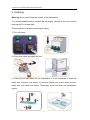
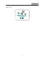
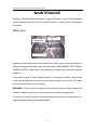
AM60E DISHWASHER
INSTALLATION AND OPERATION
INSTRUCTION
HOBART FOOD EQUIPMENT CO.,LTD
FORM 7153069XE
V1.2
V1.1 2013.01
2012.08
AM60E DISHWASHER OPERATION INSTRUCTION
1
AM60E DISHWASHER OPERATION INSTRUCTION
CONTENT
GENERAL …………………………………………………………2
INSTALLATION……………………………………………………4
Unpacking………………………………………………………………………4
Proper place……………………………………………………………………4
Conversion ……………………………………………………………………6
Electrical Connection…………………………………………………………6
Plumbing Connection…………………………………………………………9
OPERATION……………………………………………………12
Opening…………………………………………………………………………12
Warm-up………………………………………………………………………… 12
Preparations ……………………………………………………………………13
Washing…………………………………………………………………………14
Cycle selecting…………………………………………………………………14
Cleaning…………………………………………………………………………15
MAINTENANCE…………………………………………………17
TROUBLESHOOTING………………………………………….18
SERVICE……………………………………………………………19
1
Installation, operation and maintenance of
AM60E dishwasher
Please save these instructions
GENERAL
The AM60E dishwashers are semi-automatic machines. Special design of three
doors,which can be simultaneously opened,allow the rack to be pushed in and
out. Unique incorporate wash arms of washing and rinse system, improve
efficiently overall property of machines, installation, removing and
washing of wash arms may become more easily.
2
AM60E DISHWASHER OPERATION INSTRUCTION
AM60E dishwashers can fill automatically and two kind of wash time can be
selected. When doors of AM60E dishwashers are opened, machines are stopped
immediately. When water level of tanks is normal, open the door to push the rack
in, then closed the door,an automatic wash and rinse cycles begins. If machines
are short of water,close the door,machines can fill automatically. When water
level is normal, an automatic wash and rinse cycle begins.
Electrical booster heat options (6KW and 12KW, please explain clearly before
order) include a sealed booster or an open booster tank. In Addition, Dish table
heights may be specified at time of order for 800mm (31.5 inches) or 860mm
(33.875 inches).
Basic parameter:
Wash cycle(s)
60/90
Wash capability (rack/hour)
60
rack dimension(mm)
500×500
Door opening height (mm)
420
Dimension
(width-depth-height)(mm)
695×701×1440
Wash pump power(KW)
0.73
Tank electric heat power(KW)
2
Booster electric heat power(KW)
6 or12(options)
Tank capacitance (L)
20
Water consumption (L/rack)
3.0
Machine weight(Kg)
130
3
INSTALLATIONS
Unpacking
Immediately after unpacking, check for possible shipping damage. If the
dishwasher is found to be damaged, save the package materials and contact the
carrier within 15 days of delivery. Please take out parts of scene installation
(overflow pipe, vent cover), manuals and maintenance card. Please fill out
necessary information carefully.
Before installation, check the electrical service to be sure it agrees with the
electrical specifications on the data plate located on the right side of machines.
Circuit diagram located backside of panel-front.
Location
Place the dishwasher in its operating location. Turn the leveling feet as required
to level the machine and adjust to the desired height. Before finalizing the
location, make sure that consideration has been given for the electrical conduit,
water supply, drain connection, gas booster location (if applicable),tabling,
chemical feeder replenishment(if applicable),daily cleaning, maintenance and
adequate clearance for opening the doors(Fig.1)
4
AM60E DISHWASHER OPERATION INSTRUCTION
DISH TABLE
FILL HOSE
DRAIN
WALL
WALL
THE SPACE BETWEEN WALL AND MACHINE IS AT LEAST 100 MM
Fig.1
Notes: The dishwasher must be level before any connections of circuit, inlet
piping and drain piping are made.
Dish table should be turned down and fitted into the dishwasher (Fig.2). Use a
suitable sealer between table and tank lip to prevent leakage.
A hood or vent may be required in order to meet local codes. The ventilation
volume should be
more than 2.8m3/min
in case of using hood
or vent (supplied
by others).
5
Convert From Straight-Through To Corner Operation
For corner operation, remove the rack guide and baffle (Fig.3) from the front.
Re-install the rack guide on the side and use screws to re-install the baffle in the
front.
CORNER
STRAIGHT-THROUGH
RACK GUIDE
RE-INSTALL
BAFFLE HERE
Fig.3
Electrical Connections
Electrical Data
Volts/Hz/ Ph
No booster
6KW Electrical booster
12KW Electrical booster
Min. Circuit Ampacity/ Max. Protective device
Min. Circuit Ampacity/ Max. Protective device
Min. Circuit Ampacity/ Max. Protective device AMPS
AMPS
AMPS
220/50/1
25
220/60/1
25
200/50/3
15
45
75
200/60/3
15
45
75
220/50/3
15
41
69
220/60/3
15
41
69
380/60/3
10
15
24
380-415/50/3
10
15
24
6
AM60E DISHWASHER OPERATION INSTRUCTION
WARNING:Electrical and grounding connections must comply with applicable
portions of the national electrical code and/or other local codes.
WARNING: A fused disconnects or circuit breaker with electrical leaking
protector (not supplied) must be installed in the electrical line supplying the
dishwasher and should meet the requirements of your local electrical code.
WARNING: Disconnect the electrical power supply and place a tag at the
disconnect switch indicating that you are working on the circuit.
Power supply (If power cable is not supplied with machine)
Remove the side panel.
Let the power cable thread the wiring hole on the bear panel. And fix the cable
via the cable clip.
7
Let the cable thread the cable bushing, and strip the cable if necessary.
Connect the power cable to terminals on the control board according to the
picture.
Please install leakage protection switch. The horizontal distance between power
switch and one side of machine is about 0.5m. The height of power switch is
about 1.7m. Five-line cable is prepared for AM60E dishwashers. Refer to the
electrical diagram on the side of side panel. Connect the electrical supply wires
with different colors to terminal block(Fig.4).
Fig.4
8
AM60E DISHWASHER OPERATION INSTRUCTION
Plumbing Connections
Water supply
Warning: Plumbing connections must comply with applicable sanitary,
safety and plumbing codes.
Please install 3/4” valve in the range of 1m to machines. Connect the Water pipe
to the incoming water supply (3/4”).The water supplied hardness should be ≤
Incoming water temperature requirements
Temperature
C
F
With 6KW Electrical Booster
55~60
131~140
With 12KW Electrical Booster
25~60
77~140
Incoming water pressure requirements
Pressure(dynamic)
M Pa
Kg/cm2
Standard machines
0.1-0.6
1-6
With rinse pump
0.05-0.6
0.5-6
0.5mmol/L. If hardness exceed limit, please increase softening system to make
sure machine can operate normally.
Note: The water hardness should be ≤0.5mmol/L. If not, water softener is
strongly recommended. Or else, may affect the warranty set out in the
standard condition of sale.
Note: In case of line dynamic pressure less than 0.098MPa on sealed booster
machine; or line dynamic pressure less than 0.049MPa on open booster
machine,a pressure-pump must be installed (by others); in case of line
static pressure more than 0.784MPa,a pressure reducer must be installed
(by others).
9
Drain
Connect the 11/4” NPT drain connector under the wash tank to a suitable drain. If
a grease trap is required by code, it should have a minimum flow capacity of 95.5
liters per minute (21 gallons per minute).
Power supply for detergent dispenser and/or rinse sanitizer feeder
(by others)
Terminals DSP1 and DSP2 in the control box allow connection of detergent
dispenser (by others). RPS1 and RPS2 terminal allow connections of a rinse
sanitizer feeder (by others) with maximum current of 3 Amps (Fig.4).
DSP1-DSP2 is powered during the wash cycle. RPS1-RPS2 is powered during
the rinse cycle. Refer to the electrical diagram on the side of side panel.
Fig.4
Notes: The move of control box must be considered during wire connection and
provide extrusions of wire.
Notes: Please use insulated jacket wire above 600 Volts and do not use wire of
light and electric ring.
10
AM60E
E DISHWASHER
ER OPERATION
N INSTRUCTIO
ON
Rinse
e Agent Connectio
C
on
G1/8” INTERNAL THR
READS
Remo
ove front pa
anel to loca
ate rinse agent
a
conne
ection poiints.
Tw
wo conneccting
pointss for rinse
e agent arre provided
d. In
sealed
d booster machine, one is loccated
at the
e upper fro
ont side of
o booster and
allowss rinse agent to inject into the
booster tank. An
nother is lo
ocated boo
oster
Fig 5
outlet pipe uppe
er the boosster tank and
a allows rinse agen
nt to injectt into the rinse
pipe (Fig.
(
5a). In
n open boo
oster mach
hine, one is located at
a the uppe
er right sid
de of
booster and allo
ows rinse agent
a
to injject into th
he booster tank. Anotther is loca
ated
rinse pump outle
et pipe and
d allows rin
nse agent to
t inject intto the rinse
e pipe (Fig. 5b).
Selecct a suitable
e point acccording to the chemical require
ement. Use
e a spanne
er to
loosen
n the plug and conne
ect rinse ag
gent pipe with
w a suita
able sealing material.
Partss installattion
After installation
n, please in
nstall strain
ner
o
pip
pe (Fig.6)
and overflow
Fig.6
11
OPE
ERATION
1.Opening
O
1).Op
pen valve, push switcch, check detergent
d
and
a sanitizzer and che
eck installa
ation
of stra
ainer and drain
d
pipe.
2).C
Close the door, turn th
he power on
o and indiicator begins to shine
e.
2. Warm-up
W
Machine automa
atically fill and heat. When the temperatu
ure reachess 70C°and
d 82
C°, machine
m
be
egins to sta
andby mod
de.
Therm
mometer: left therm
mometer express temperatu
t
ure of was
sh tank, and
ess rinse w
water.
right thermometer expre
12
AM60E
E DISHWASHER
ER OPERATION
N INSTRUCTIO
ON
Advised temperatu
ure
Water for wash
55°C-65°C(131
C
°F- 1449°F)
Water for rinse
82°C-90°C(180
C
°F-1994°F)
3.Preparat
P
ions
1) Scrrape the dishes to remove large
e particles of food an
nd debris and marinatte in
the wa
ater.
Marinating
R
Removing
large particless
2) Pre
eparation
Prrewashing
Correctt placementt
hes may be not wash
hed cleanly
y.
Warning:If disshes are placed incorrrectly, dish
13
4. Washing
W
O
Open
the do
oor, push the
t rack in, and then close the door. Macchine begin
ns to
w
work.
Washing
sto
op
rinse
e. After rins
se, open th
he door, pu
ush dishes
s out,
an
nd then takke out dish
hes.
P
Pushing
rackk in
Washing
Ta
aking out
Warning: pleasse cut off power,
p
waitt 10 secon
nds, make wash arm
m stop to make
m
sure not
n to scald
d others if you want to
t push in dishes afte
er washing
g cycle.
5.Cycle
C
Se
electing
Select time acccording to dirtiness of
o dishes. “Ⅰ”-60s wa
ash cycle, “Ⅱ”-90s wash
w
cycle..
Working cycle data
W
Working
cycle(s)
6
60
90
Wash time((s)
4
42
72
P
Pause
time(s)
4
4
Rinse time((s)
14
14
Drain
n: Lift the standpipe to
o drain the
e wash tank
14
AM60E DISHWASHER OPERATION INSTRUCTION
6. Cleaning
Warning: Never hose down the outside of the dishwasher
It is recommended that the machine be thoroughly cleaned at the end of each
working shift or at least daily.
The procedures of machine cleaning as follow:
1) Turn off power.
2) Close inlet valve and open the door.
3) Clean off the dish table into the dishwasher. Lift the standpipe to drain the
wash tank. Remove and empty the strainer basket and pump intake screen,
wash and rinse them thoroughly. Thoroughly clean and flush the dishwasher
interior.
15
4) Replace intake screen and strainer basket. Leave the doors open to allow the
interior to dry.
16
AM60E DISHWASHER OPERATION INSTRUCTION
MAINTENANCE
Warning: Disconnect electrical power supply and place a tag at the disconnect
switch indicating that the circuit is being worked on before any maintenance
procedure.
Wash arms
Wash Arm
Rinse Arm
Knurled Disk
Upper and lower wash/rinse arms should turn freely and continue turning for a
while after being whirled by hand. To check arms, DISCONNECT ELECTRICAL
POWER SUPPLY, rotate arms, and remove any obstructions causing improper
operation.
If the strainer pans or pump intake screen is not properly in place, obstructions
(such as food particles or bones) may clog the wash arm nozzles. The wash
arms are easily removed for cleaning.
WARNING: There may be hot water in the wash/rinse arms, please wait at least
5 minutes after turning off the machine before removing the wash arms.
To remove the arms, unscrew the knurled disk on the arms and take them out.
Upper and lower arms are interchangeable.
17
TROUBLESHOOTING
This section may help you avoid a service call. However, if a symptom persists
after the possible causes have been checked, please contact HOBART local
service departments.
SYMPTOM
POSSIBLE CAUSES/SUGGESTED ACTIONS
z Open doors and hold for 2 seconds, close it again
No machine
z Blown fuse or tripped circuit breaker at power supply
operation
z Blown fuse FU3 at control circuit
Long wash z Water temperature in booster is too low. Warm-up time was not
cycle
enough. Check thermostats and heaters.
z Insufficient water circulation due to obstruction at pump intake
screen. Disconnect power supply, drain wash tank and check.
z Incorrect water temperature. Insufficient warm-up time. Check
circuit breaker, thermostat and heater.
Dishes not
z Incorrect detergent
clean
representative.
dispensing.
Contact
your
detergent
z Excessive mineral deposits through wash and rinse system.
Deliming may be necessary.
z Improperly loaded racks.
z Incorrect rinse water temperature.
z Loss of water pressure due to pump obstruction.
Spotting
silverware,
glasses,
and dishes
z Excessively hardness of water.
z Incorrect detergent for water type.
z Incorrect rinse additive for water type.
z Incorrect concentration of detergent, rinse additive and/or
sanitizer.
Inadequate
rinse
z Dirty line strainer causing reduced water flow. Turn off water
supply, disconnect water supply pipe and solenoid valve,
withdraw and clean screen. Reassemble.
z Low supply line pressure
18
AM60E DISHWASHER OPERATION INSTRUCTION
SYMPTOM
POSSIBLE CAUSES/SUGGESTED ACTIONS
z Foreign material preventing proper valve operation. Note: a
critical period is soon after installation when pipe compound or
metal shavings may lodge at the valve seat. Shut off supply line.
Unscrew and lift bonnet from valve body. Clean valve and
reassemble
Leaking
valve
z If a solenoid valve is malfunctioning, it is recommended that you
contact Service
z Dirty line strainer causing reduced water flow. Turn off water
supply, disconnect water supply pipe and solenoid valve, withdraw
No or slow
and clean screen. Reassemble
fill
z Low supply line pressure
Service
Contact your local Hobart-authorized service office for any repairs or
adjustments needed on this equipment.
As continued product improvement is a policy of HOBART,
specifications are subject to change without notice.
19
CE Certification
20
Dishwasher Maintenance
For AMX/AM900 H502L/E502L AM50E/AM60E
Clean machine(Customer)
Items
Content
1
Tank flat strainer
Visual inspection & cleaning
2
Wash tank housing
Visual inspection (lime deposits etc.)
3
Wash & rinse arms
Removing & cleaning of upper and lower wash arms. Tighten screws when installing.
4
Overflow & Tank strainer
Check overflow tube in right place
5
Milled nut
Check wash arm milled nut before operation, and tight it.
Machine inspection (Service)
Machine maintenance after 0.5 year or 20 000 cycles. The maintenance must be carried out by authorized
service technicians.
Component
Inspection
1
General condition (first impression)
- Visual control, condition
Machine Type
All
2
Machine tightness
- Visual control, become less crowded
All
3
Fill hose, fill valve & air gap system
- condition and function
All
4
Water level wash tank, air chamber
- Condition & function due to visual control
- Check soil level inside air chamber
AMX/AM900
5
Pressure transmitter, pressure hose
- Check soil level inside air chamber
- Condition & function due to visual control
- Check sealing of pressure hose
All
6
Booster, rinse pump, rinse manifold
- Condition & function due to visual control
- Tightness
- Check Booster water level using routine S56 (Service manual)
AMX/AM900
7
Wash & rinse arms
- Check wash & rinse arm spinning
- Removing & cleaning of upper and lower rinse and wash arms
- Visual inspection of abrasion and lime deposits of wash & rinse arms, replace it when
necessary.
All
8
Wash arm bearing, sliding ring and
milled nut
- Visual inspection of abrasion and lime deposits of wash arm bearing sliding ring and milled
nut, replace it when necessary.
Hxle-wash arm(00-883452-001), milled nut(7159006-6), gasket(00-775933-003).
All
9
W h arm washer
Wash
h
- Visual inspection
p
of abrasion,, warping
p g and deformation of wash arm washer,, replace
p
it.
Teflon washer(00-774072-001/002, 00-774072-007).
All
10
Safety equipment: hood end switch
- Check function
All
11
Bosster and tank heating elements
- Condition, fuction and tightness
All
Door & Hoodlift
- Operating noise (rolls)
- Adujstment of the hood in standby position
- Visual control, condition, tightness
- Function check
- Function, check door slide bearing, doorstop damper, replace it when necessary.
12
AMX/AM900
AM50E/60E
13
Door mechanism clamping force
- Check clamping force
AMX/AM900 AM60E
14
Bow
- Function, check bow bearing
AMX/AM900
15
Tighness of top cover / BAE
- Visual inspection: tightness top cover and BAE
- Humidity in BAE, if necessary replace and change seal top cover
AMX/AM900
H(E)502L(P)
16
17
Machine control unit, contactor, fuses &
- Check condition and function, if necessary test run
touch panel
Control unit & circuit board:
______
- Visual inspection, check moisture penetration
number of cycles
All
All
18
Detergent & rinse aid dosing
- Check function
- Check dosing level
All
19
Detergent & Rinse aid hoses
- Check tightness, especially on interface hose / connection nipple
- Exchange all hoses every 2 years
All
20
Chemical sensor for rinse- and
detergent agent
- Check switching function
All
21
Drain pump
- Check residual water after drain, if necessary check drain pump (impeller)
All
22
Drain hose
- Visual inspection, exchange by porosity or damaging
All
23
Wash & rinse result
- Performance control
All
24
Softener (if existing)
- Visual inspection, condition, corrosion ect.
- Check hardness
All
25
Descale
-Check the deposit of scale in wash tank and booster, descale it promptly.
All
27
If necessary water analysis
_____°d (GH); ____°d (KH); ____µS
Test run
28
Wash pump
26
All
All
-Check the leakage of shaft seal. if necessary replace and change shaft seal.
V1.0 2013-1-9