1
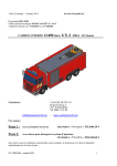
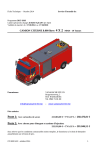
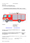
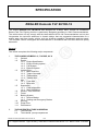
SPECIFICATION
ZIEGLER Komodo FLF 60/100-12
The Ziegler Komodo FLF 60/100-12 was designed as a Major ARFF Vehicle for Aerodrome
Rescue and Fire Fighting Vehicle is particularly designed according to ICAO Recommendations.
The vehicle does not only comply with the latest edition NFPA 414 recommendations too but also
incorporates the technical advances in chassis design that are suggested characteristics for a
mobile water and foam tender vehicle, such as all-terrain capability, acceleration and top speed.
The complete vehicle is designed and manufactured in accordance with ISO 9001:2008 for quality
assurance.
General :
The vehicle comprises the following major components:
1.
THE CHASSIS KOMODO -6-, 710 BHP, 6 X 6
1.1
General
1.2
Engine
1.2.1 Engine Specification
1.2.2 Engine Cooling system
1.2.3 Fuel System
1.2.4 Exhaust System
1.3
Vehicle Drive
1.3.1 Main Gear Box
1.3.2 Torque Converter
1.3.3 Transmission
1.3.4 Transfer box
1.4
Axle
1.4.1 Front Axle
1.4.2 Rear Axle
1.5
Suspension
1.5.1 Front suspension
1.5.2 Rear suspension
1.6
Wheels, Tires and Rims
1.7
Frame
1.8
Braking System
1.8.1 Service Brakes
1.8.2 Parking and Emergency Brakes
1.9
Steering
1.10 Pump Drive
1.11 Performance
2.
THE SUPERSTRUCTURE IN GENERAL
2.1
The crew cab
2.2
The material -/pump compartment
100222 Technical Specification FLF 60/100-12
1/20
PT. Ziegler Indonesia · Lippo Cikarang · Delta Silicon Industrial Park Blok A 10-2 · Bekasi 17550 · Indonesia
SPECIFICATION
2.3
Engine Hood / Cover
3.
THE FIRE EXTINGUISHING UNITS
3.1
The water tank 10.000 L
3.2
The foam concentrate tank 1.200 L
3.3
The Ziegler dual stage centrifugal high-pressure fire pump unit
3.3.1 The Ziegler priming system pump
3.3.2 The rapid intervention hose reels
3.4
The Ziegler foam pump proportioning system
3.5
The forward and body ground protection system
3.6
The Ziegler water/foam monitor
3.7
Flushing
3.8
Pressure relieve valve
3.9
Operation and controls
3.9.1 Operation in the crew cab
4.
PIPING
4.1
Layout
4.2
Materials and welding
4.3
Valves, fittings and couplings
5.
ELECTRICAL SYSTEM
5.1
General
5.2
Vehicle lighting
5.2.1 Vehicle road lighting
5.2.2 Emergency warning equipment
5.2.3 Elevating mast and floodlight assembly
5.3
A.C main supply 220 volt
6.
PAINTWORK
6.1
General
6.2
Color scheme and standards
6.3
Anti - corrosion treatment
6.4
Interior
7.
EQUIPMENT LIST
7.1
Rescue equipment
7.2
Intercom system
7.3
Add. fire fighting equipment
8.
OPERATIONS AND MAINTENANCE, SPARE PARTS MANUAL FOR CHASSIS AND
FIRE EXTINGUISHING UNITS.
100222 Technical Specification FLF 60/100-12
2/20
PT. Ziegler Indonesia · Lippo Cikarang · Delta Silicon Industrial Park Blok A 10-2 · Bekasi 17550 · Indonesia
SPECIFICATION
1. CHASSIS
1.1.
GENERAL
The chassis is a permanent all wheel drive, rear engine 6 x 6, single track, with a high
top speed, excellent cross country performance, together extreme reliability and
operational simplicity. A center steering position provides optimum accessibility.
Maintenance is made simple by detail attention to the need for access to various vehicle
systems.
1.2.
ENGINE
1.2.1. Engine Specification
Detroit Diesel………………………8V92TA
Type………………………………...8V92TA
Piston Displacement………………24.1 liters
Gross output……………………….710 bhp
Rated maximum speed…………..2300 rev/min
All oil fill points and dipsticks are extended to the top of the engine frame and
engine hour meter is fitted adjacent to engine.
1.2.2. Engine Cooling System
A radiator is mounted behind the engine at the rear of the chassis with a direct
drive fan.
The system includes an engine mounted transmission oil-to-water heat
exchanger.
The system is designed to operate efficiently in a temperature range of +44
degrees C to –20 degrees C ambient. The radiator is fitted with a low coolant
alarm with visual warning in the cab.
1.2.3. Fuel System
Filtration is through spin-on replaceable elements. A 227 liter steel fuel tank is
mounted at the rear of the chassis.
A fuel shut off control is fitted at the rear of the vehicle.
100222 Technical Specification FLF 60/100-12
3/20
PT. Ziegler Indonesia · Lippo Cikarang · Delta Silicon Industrial Park Blok A 10-2 · Bekasi 17550 · Indonesia
SPECIFICATION
1.2.4. Exhaust System
One silencer is mounted above the engine and discharges rearwards. The
system is constructed in steel and painted with high temperature resistant
aluminum paint.
1.3
VEHICLE DRIVE
1.3.1. Main Gearbox
The vehicle is fitted with a fully automatic gearbox and torque converter.
1.3.2. Torque Converter
Make………………………..Allison single stage 3 element – TC 488.
1.3.3. Transmission
Make………………………..Allison
Model……………………….CLT755CEC
Type………………………...Constant mesh, spur type planetary
1.3.4. Transfer Box
The transfer box is a two speed permanent constant mesh unit.
Engagement of high/low ratio is operated pneumatically actuated sliding dog
clutches from separate controls in the driver’s cab.
Another separate control engages the differential locks in the front and rear axle.
1.4.
AXLES
1.4.1. Front Axle
Make…………………………Kirkstall
Type………………………….SD66-12-1S
Differential lock……………..Air operated cross-lock
1.4.2. Rear Axle
Foremost
Make and model…………..Kirkstall
Type…………………………D66-12-1SHF
Differential lock…………….Air operated cross locks
100222 Technical Specification FLF 60/100-12
4/20
PT. Ziegler Indonesia · Lippo Cikarang · Delta Silicon Industrial Park Blok A 10-2 · Bekasi 17550 · Indonesia
SPECIFICATION
Rearmost
Make and model…………..Kirkstall
Type………………………...D66-12-1S
Differential lock…………….Air operated cross locks
1.5
SUSPENSION
1.5.1. Front Suspension
The front suspension consists of semi-elliptic leaf springs and double acting
hydraulic dampers.
1.5.2. Rear Suspension
The rear suspension consists of semi-elliptic leaf springs and radius arms on a
central pivoting bogie.
1.6
WHEELS, TYRES AND RIM
Michelin 475/80 R20 XML tire equipment is fitted. One (1) spare wheels and tires are
supplied loose together with a maintenance standard tool kit.
1.7
FRAME
The frame is of bolted construction using hot pressed channel section side members
with formed and fabricated cross members. Towing loops are provided front and rear.
A drop front provides low floor height for the cab.
1.8
BRAKING SYSTEM
1.8.1. Service Brakes
An air operated system with split brake circuits controlling the front and rear
brakes are fitted complying with EEC standards and UK C&U Regulations.
The service brakes are controlled by a dual foot valve. The parking spring
brakes are controlled by a hand valve.
All reservoirs are located within the chassis rails.
A quick release coupling is provided at the rear to enable the reservoirs to be
charged from an external source of compressed air.
An engine driven compressor provides air to the reservoirs via an air dryer.
Manual drain valves are fitted to all reservoirs
ABS (Advanced Braking System) is fitted as standard.
100222 Technical Specification FLF 60/100-12
5/20
PT. Ziegler Indonesia · Lippo Cikarang · Delta Silicon Industrial Park Blok A 10-2 · Bekasi 17550 · Indonesia
SPECIFICATION
1.8.2
Parking and Emergency Brakes
Hand valve operated spring brakes are fitted for parking and to provide
emergency braking.
The parking brakes release within 12 seconds of engine starting with empty
reservoirs.
Emergency spring brakes only are available until the service reservoirs are
charged.
Note :
All pipe work on the axles is of metal tubing. Elsewhere high quality nylon tubing
(fire retardant) is used and is protected where necessary by a heavy duty spiral
wrap strip. A high grade end-fitting system is used.
All piping is located within and below the chassis rail top flange.
1.9.
STEERING
The steering position is central and is equipped with hydraulic power assistance. Power
is provided by an integral ball-and-nut power steering box with additional ram
assistance.
Steering system manufacturer-ZF.
1.10
Pump Drive
A close coupled hydraulic power divider is fitted with an engine driven power take off,
side mounted, allowing the pump to operated whilst the vehicle is stationary or on the
move (pump and roll).
Make of power divider………Cushman, series 285
1.11.
Performance
0 - 80 kph in 32 secs, top speed 115 kph by 30.000 kgs.
Approach angle
:
30 deg
Tilt angle
:
28 deg
Breaking 32 - 0 kph
:
11 m
Breaking 64 - 0 kph
:
40 m
Gradeability
:
50%
Depression
:
± 12,5 m from the front bumper vehicle.
100222 Technical Specification FLF 60/100-12
6/20
PT. Ziegler Indonesia · Lippo Cikarang · Delta Silicon Industrial Park Blok A 10-2 · Bekasi 17550 · Indonesia
SPECIFICATION
2.
THE SUPERSTRUCTURE IN GENERAL :
All major components described above are mounted on the vehicle chassis in accordance
with the appropriate instructions given and approved by the vehicle chassis manufacturer.
Flexible shock mounts and connections are utilized in order to eliminate any torsion when
traversing rough terrain.
The underside of the body will be treated with an approved non-flammable protective
compound.
Provision will be made for the attachment of vehicle registration plates on the front and rear
of the vehicle in positions where they will not be damaged by normal vehicular movement.
Adequate metal instruction plates and engraved to cover operation of all equipment will be
provided adjacent to the individual controls.
Space will be provided adjacent to the driver for installation of radio equipment. The space
will be allocated such that the driver will be able to both reach the radio loudspeaker
mounted on the equipment.
A crash grill will be provided to protect the radiator, headlights and body from damage when
driving through fences, shrub etc. Heavy duty bumper bars are mounted at the front of the
vehicle.
All control handles, grab rails and fittings are chrome plated or coated with suitable plastic
material.
Kick strips and/or tread plates to protect body and paint work from damage are provided
where considered necessary. All steps, platforms, and walkways are to be surfaced with
non-skid aluminum chequered plate. Step running boards are installed on the back of
engine hood.
Deck rails are provided each side of the monitor platform. Further handrails are provided
where necessary to assist in crew safety.
On both sides of the body, there are 4 operation light (2 on each side) lighted from the cabin
to support the firemen at night operation.
The vehicle consists of the following major Modules components mounted on the chassis :
- Driver’s/crew cabin
- Pump unit and equipment lockers
- Water/foam tank
- Engine Hood
100222 Technical Specification FLF 60/100-12
7/20
PT. Ziegler Indonesia · Lippo Cikarang · Delta Silicon Industrial Park Blok A 10-2 · Bekasi 17550 · Indonesia
SPECIFICATION
2.1
The crew cab
The cab construction consists of a strong stainless steel framework, which has been
designed and computer checked for strength, to ensure crew protection in the event
of external impact. Prior to assembly of paneling, doors, windows, etc the frame is
treated to minimize corrosion.
The two doors fully trimmed four man cab with forward central driving position is
constructed of corrosion resistant welded stainless steel & GPP sheets. This
construction affords maximum crew crash protection.
The inside cabin is insulated with plastic, vinyl, or glass reinforced plastic in order to
isolate the noise in the cabin.
Large windows provide good all round visibility through laminated safety glass and
toughened side windows. Upward vision : ± 24º above horizontal. Horizontal vision in
excess of 240º. Triple wipers with traveling jet washers are fitted.
A low through floor and a wide door on each side of the cab allows rapid entry and
exit.
Access to the monitor platform is provided at the rear left side of the cab through a
large sliding hatch. The hatch is complete with weatherproof seals, grab handle and
slam lock, and the step are made from aluminum alloy raised pattern. The platform is
sizable for 2 persons to operate the monitor locally.
The ergonomically lay out instrument panel is equipped with a full set of back lit
instruments, illuminated switches and a complete warning system with indicator
lights and buzzers.
Provision is made in the Cab behind the seat including driver to mount three
Breathing Apparatus to easy donning. At the rear wall of cabin there are 3 hangers
for fire suits
The crew cab is equipped with Air Conditioning system to control the temperature in
the cabin.
2.2
The Material - Pump Compartment
The pump unit is protected by a hood with large flaps for maintenance laterally and in
the roof.
Lockers closed by allow roller shutters, make Ziegler (AZ-shutter).
These shutters are composed of specially extruded box profiles which interlock, thus
avoiding they need for separate hinges.
When the shutter doors are closed, the entry of dust and water is avoided by 3
rubber lip seals; 2 vertical ones and one horizontal. The weight of the (partly) opened
shutter door is counter balanced by a spring loaded roller.
100222 Technical Specification FLF 60/100-12
8/20
PT. Ziegler Indonesia · Lippo Cikarang · Delta Silicon Industrial Park Blok A 10-2 · Bekasi 17550 · Indonesia
SPECIFICATION
In the middle of the double handle a push-button is situated to unlock the roller
shutter.
The equipment locker superstructure is a solid all steel construction in light weight
design from welded square-profiles. Sheeting of the lateral, front and rear walls by
aluminum sheet. Equipment locker lighted by electric switches.
The fire-fighting equipment is stored in the equipment lockers or safely located in
boxes and/or fixing devices on the roof and in the driver’s cab and is easily to be
removed.
Access to the roof is made via an ascending ladder at the rear side at the vehicle.
2.3
Engine Hood / Cover :
The rear engine cover is a single module enclosing the engine, batteries, fuel tank
etc. The module is a fixed type with hydraulic lift off panels providing full access to
the engine and ancillary components.
The roof of the module is manufactured from open mesh aluminum. A hinged panel
in the roof assists with top access to the engine and ancillary equipment.
At the rear of the module, an aperture is provided for the radiator assembly, to
ensure good cooling ability.
3.
THE FIRE EXTINGUISHING UNITS :
3.1
The water tank : 10.000 L
The water tank is made from Top Quality Glass Reinforced Fiber and has a minimum
capacity of 10.000 liters usable amount of water. The tank is suitably baffled in
longitudinal and transverse direction to prevent surge during cornering, breaking or
traversing rough terrain. The shape and mounting of the tank is such as to bring the
center of gravity as low as possible. The lateral wall is also the external wall with
beads. The upper tank surface can be walked-on and is provided with anti-slip cover.
The tank is assembled to the chassis on heavy duty flexible mountings to minimize
torsional loads which occur during “Off road” operation.
The tank outlet is dimensioned for maximum output with minimal pump cavitations.
The tank is equipped with a combination aeration/dearation and overflow unit.
Adequately dimensioned manhole 450 mm i.d. with quick-release dome lid are
provided, which can also be utilized for filling of the tank.
Filling of the tank from an external pressure source is through two 2,5” couplings
fitted on the left hand side of the vehicle with manual close valve.
100222 Technical Specification FLF 60/100-12
9/20
PT. Ziegler Indonesia · Lippo Cikarang · Delta Silicon Industrial Park Blok A 10-2 · Bekasi 17550 · Indonesia
SPECIFICATION
Draining of the tank is by a pipe, complete with a manually operated valve,
terminated at the side of the vehicle.
Electrical filling level indicator and remote indicator in the driver’s cab, calibrated in
four equal increments.
Four section lamp of water tank level indicator is provided at both sides of the vehicle
located directly behind the cabin, so that the firemen be able to see from distance the
availability of water in the tank.
3.2
The foam concentrate tank : 1.200 L
The tank is manufactured integrally with the water tank from top quality glass
reinforced plastic coated internally to allow use with all current foam compounds
including A.F.F.F.
The tank has a minimum capacity of 1.200 liters of usable amount of foaming agent,
and also designed to allow the mixture of 2 water volume with 1 foam volume at the
6% operation.
Baffle plates in longitudinal and cross direction are provided to prevent surge during
cornering, braking or traversing rough terrain.
The tank base is sloped to the outlet valve to ensure complete drainage of contents.
The tank is equipped with a combination aeration/de-aeration.
Drainage of the tank is by a pipe, complete with a manually operated valve,
terminated at the side below of the vehicle.
Tank fittings :
- 1 x manhole with quick-release dome lid, for inspection, cleaning and filling from
cans;
- 1 x tank-to-proportioner feed line, with remote-controlled valve, i.d. 80 mm;
- 2 x separate filling respect. draining connection Storz 38, with Storz (38) mm
solid coupling and blank cap, and chain with manually operated valve.
- 1 x overflow with aeration and deaeration pneumatically actuated .
- 1 x electric contents indication with remote indication in the driver’s cab,
calibrated in four equal increments.
- A separate electric pump, to fill Foam compound from outside source. (Drums
etc) will be supplied - 220 V.
100222 Technical Specification FLF 60/100-12
10/20
PT. Ziegler Indonesia · Lippo Cikarang · Delta Silicon Industrial Park Blok A 10-2 · Bekasi 17550 · Indonesia
SPECIFICATION
3.3
The Ziegler dual stage centrifugal high-pressure fire pump unit :
The Ziegler dual stage centrifugal high-pressure fire pump is installed in front of the
water/foam tank. Thus, the pump operation is entirely independent from driving. The
whole pump unit is designed for quick and complete draining.
The Ziegler dual stage centrifugal high pressure fire pump FP 60/10-2HH. Pump
volute, impeller and pump cover machined from high grade sea-water resistant
aluminum alloy casting G-AlMg 3 Si. The pump shaft is machined from stainless
steel 1.4021 (x 20 CR 13), split rings are made of acid resistant stainless steel
1.4059 (G-X 22 CrNi 17).
Medium Pressure
Output rating
:
6.000 l/min at 10 bar
High Pressure
Output rating
:
250 l/min at 40 bar
Coupling systems
Pump drive
:
:
Storz
Power Divider
Foam side Line :
-
2 (two) flaked 2.5” x 30 m (Pionier 500), storz coupling, c/w jet spray pistol nozzle
for side delivery outlet (one on each side) with restricted regulator to ensure the
constant flow in case of the roof monitor and side delivery outlet are in operation
simultaneously.
3.3.1
Priming system :
The TROKOMAT - PLUS is an advanced reciprocating priming device that
engages and disengages fully automatically thus simplifying pump operation
to a minimum. The TROKOMAT - PLUS can is controlled by the water
pressure of the pump only and does not need any auxiliary fluids.
TROKOMAT - PLUS locker enables parking of vehicle with pump flooded for
immediate action.
3.3.2
The rapid intervention hose reels :
2 rapid intervention hand lines, each comprising a pivot-mounted 900
swiveling, electrical rewind hose reel, coiled with 30 m - 28 mm diameter
hose, with Jet/Spray Nozzle.
The hose reels are equipped with overrun brake, locking device and
drainage.
Flow rate
Throw
100222 Technical Specification FLF 60/100-12
: approx 230 l/min.
: approx 20 m
11/20
PT. Ziegler Indonesia · Lippo Cikarang · Delta Silicon Industrial Park Blok A 10-2 · Bekasi 17550 · Indonesia
SPECIFICATION
3.4
The Ziegler foam pump proportioning system :
The Ziegler MAD 50 is an automatically and mechanically controlled round-the-pump
proportioning system, comprising an automatic control unit and one Ziegler ZPV 500
round-the-pump proportioner.
The automatic control unit meters and controls the foam concentrate flow in direct
proportion to the water flow at the preset proportion (admixing ratio) of 3, 6 or 8 per
cent. Setting of admixing ratio is remote-controlled at the operating panel. The
Ziegler proportioner ZPV 500 has a capacity of max. 500 l/min. of foam concentrate.
The proportioner is installed in a by-pass line off the delivery side of the pump.
A limited portion of water delivered under pressure from the pump is fed through the
proportioner, thus initiating an injector effect, which is utilized to suck foam from the
foam concentrate storage tank. The foam concentrate admixed is fed to the inlet side
of the pump, where it mixes with the flow of water. The capacity of the ZPV 500 is
adequate to supply sufficient foam concentrate at rates of 3 %, 6 %, 8 % from a
discharge rate of 200 l up to 5.000 l of water/foam solution. (even up to 6000 l/min if
rate is reduced to 6%)
3.5
The forward and body ground protection system :
3 forward sweep nozzles underneath the bumper bar, each with fan pattern spray
of approx. 7 m width and a reach of stream of approx. 7 m.
For the protection against ground fires 2 additional spray nozzles are installed
underneath the vehicle.
Performance of each nozzle : 240 l/m at 14 bar.
Remote control for the system is provided inside the cab.
3.6
The Ziegler water/foam monitor :
The water/foam monitor, with jet spray nozzle and deflector, output 6.000 l/min.
The turret is designed for remote control from inside driver’s cab and from the
platform by joy-stick operation.
“ZIEGLER” series type turrets embody the following unique features:
•
•
•
•
•
•
Remote control for simultaneous horizontal rotation and vertical travel by joystick.
Slip clutches for motors, can be released for manual emergency operation;
Adjustable limit switches at both ends of vertical travel and horizontal rotation;
Central duct for electrical wiring - no loose wires, revolving parts with ball
bearings horizontally and vertically.
Turret body made from high grade sea-water resistant aluminum alloy
castings for minimum weight.
Suitable for prolonged use with sea-water or brackish water and foaming
100222 Technical Specification FLF 60/100-12
12/20
PT. Ziegler Indonesia · Lippo Cikarang · Delta Silicon Industrial Park Blok A 10-2 · Bekasi 17550 · Indonesia
SPECIFICATION
•
agents including AFFF concentrates;
A double deflector is mounted on the turret, and adjustment is done
electrically.
Performance :
Discharge
Throw water
Throw foam
Horizontal rotation
Vertical swiveling range
Emergency operation
: 100 % flow = 6000 l/min. at 10 bar.
50 % flow = 3000 l/min. at 10 bar.
: approx. 80 m
: approx. 70 m
: 3300
: +600 to -150
: Hand wheels for horizontal rotation and vertical travel.
Levers for volume control and deflector control.
Materials :
- Turret body
- Foam branch
- Deflector
- Gear wheels
- Worm gear
- Worm gear spindle
:
:
:
:
:
:
Sea-water resistant aluminum alloy casting, anodized;
Stainless steel;
Stainless steel;
Gun metal casting;
Steel;
Stainless steel.
Foaming : All types of AFFF, FFFP.
An intercom system is provided between the driver and the monitor operator at the
platform.
The platform floor is designed to minimize the water accumulated on the floor where
the operator is standing.
3.7
Flushing :
On completion of the fire fighting operations, the system can be cleansed of foam
concentrate by inducing clean water downstream of the foam tank valve and
discharging through the delivery outlets.
3.8
Pressure Relief valve :
The automatic pressure relief valve is an electrical actuated unit which prevents high
pressure surges which may burst hoses on open line when branch pipes are closed.
3.9
Operation and controls :
The major controls for the fire pack are installed in a console between the driver’s
and the co-driver’s seat, distinctly separated from the controls for vehicle operation
but within immediate reach of the driver, thus featuring one-man control of the entire
vehicle.
100222 Technical Specification FLF 60/100-12
13/20
PT. Ziegler Indonesia · Lippo Cikarang · Delta Silicon Industrial Park Blok A 10-2 · Bekasi 17550 · Indonesia
SPECIFICATION
An operating panel is installed in the pump bay on the right side of the vehicle. The
remote-controlled valves are operated electro-pneumatically with compressed air
supply of the vehicle.
The operating status is shown by indicators. The whole system is controlled by a
PLC unit (Program Logic Control) which do not employ control cables, to minimize
malfunctions.
3.9.1
Cab Console and Instrumentation
Left Hand Panel
Engine start
Ignition on/off switch
Engine stop
Rear fog
Hazard warning
Deluge pump
Front axle diff lock
Rear axle diff lock
Transfer box high/low c/w warning lights
Transfer box diff lock
Console lights
Cab lights
Locker lights
Beacons
Obstruction light
Demist
Gear select lever
Parking brake control
Drivers Central Panel
Speedometer/odometer
Engine tachometer
Fuel gauge
Warning lights
Left hand indicator
High coolant temperature
Low oil
Low air
Hand brake on
A.B.S.
High beam
Gearbox in neutral
Mains connected
Alternator no charge
Low coolant level
Right hand indicator
100222 Technical Specification FLF 60/100-12
14/20
PT. Ziegler Indonesia · Lippo Cikarang · Delta Silicon Industrial Park Blok A 10-2 · Bekasi 17550 · Indonesia
SPECIFICATION
Central Top Cab Panel
Service air pressure gauge – 1
Service air pressure gauge – 2
Secondary air pressure gauge
Voltmeter
Engine coolant temperature gauge
Engine oil pressure gauge
Transmission oil temperature gauge
Clock
Steering Column
Washer and wiper controls
Horn controls
Direction indicators
Headlight flash
Right Hand Panel (Fire Fighting Panel)
Master switch
PTO Engage
Water valve
Foam valve
Left hand sideline
Right hand sideline
Ready/shutdown
Pump pressure gauge
Water tank contents lights
Foam tank contents lights
Right Hand of Driver’s Seat Side Console – Cab
PTO manual engage control
Lighting and Electrical
Wiring and switches are provided for the following:
Head lamps
Side lights with headlight
Tail lights
Stop lights
Direction indicator lights with hazard warning switch
High intensity rear fog lights
Reverse lights
The electrical circuits are protected by re-settable circuit breakers giving a
visible indication of a fault. The circuit breakers are grouped together for
convenience.
100222 Technical Specification FLF 60/100-12
15/20
PT. Ziegler Indonesia · Lippo Cikarang · Delta Silicon Industrial Park Blok A 10-2 · Bekasi 17550 · Indonesia
SPECIFICATION
Electrical Equipment
All electrical circuits are protected by circuit breakers and all wiring is
numbered at the ends of cables.
Road lighting
4 x semi-sealed beam head lamps
2 x side lamps
2 x tail lamps
2 x stop lamps
2 x reversing lamps
2 x high intensity rear fog lights
Direction indicators with hazard warning switch
Interior lighting
2 x cab lights
2 x bulkhead lights in pump compartment
2 x bulkhead lights in engine compartment
Locker lights
Warning Equipment
2 x blue rotating beacons positioned behind the cab
1x amber obstruction light positioned in center of appliance roof and to be the
highest point of appliance
1 x two tone horn
1 x audible reverse alarm
Communications intercom between driver and monitor operator
4.
PIPING
4.1
Lay out
4.2
Materials and welding
All piping and fitting carrying the water are made of hot dip galvanized steel schedule
40.
All pipes are designed to enable valves, flexible joint, etc to be removed with the
minimum of disturbance to other component and pipe work.
After welding, the welds will be cleaned carefully by means of special stain. Finally all
the different pieces of pipe work will be sprayed and fitted on the truck.
All welding is done by qualified welders to the Department of Mines & Energy
(MIGAS) Inspectorate for high pressure vessels and ASME-9 rules.
The test pressure is 1.5 x working pressure.
All hose connections are Storz type.
100222 Technical Specification FLF 60/100-12
16/20
PT. Ziegler Indonesia · Lippo Cikarang · Delta Silicon Industrial Park Blok A 10-2 · Bekasi 17550 · Indonesia
SPECIFICATION
Where ever necessary, the pipes are provided with flexible connections
(compensators) in order to avoid damage by torsion of the chassis.
Piping work for delivery outlet should covers the following connection :
- 2 x 2.5” for side delivery outlet (one on each side) with flow regulator to ensure
the constant flow of 500 lpm and 20 – 25 m throw in case of the roof monitor and
side delivery outlet are in operation simultaneously.
- 2 x 28 mm i.d rapid intervention hose reel (30 m hose length) – one on each side.
- 3 forward sweep nozzle underneath the bumper bar.
- 2 under body protection underneath the vehicle.
4.3
Valves, fittings and couplings
Housing of the valve is made of sea-water resistant aluminum alloy.
Delivery outlet couplings are of the standard type, fitted with blank caps chain
connected to the body work.
Material : aluminum alloy.
All fittings to be installed with anti-seize grease, before fitting.
5.
ELECTRICAL SYSTEM
5.1
General
In addition to the standard equipment supplied with the chassis in accordance with
the prevailing International road regulations the following equipment is supplied and
installed :
•
5.2
Lighting of all equipment lockers and pump bay, switched
on/off by proximity
switches in the AZ roller-shutters respect by contact switches at the flaps.
Vehicle lighting
5.2.1
Vehicle Road Lighting :
- Headlight
- Sidelight
- Stop-tail light
- Directional indicator front, side and rear with hazard warning facility.
- Reverse light with audible warning automatically operated when reverse
gear is selected.
- High intensity rear fog light.
Others lighting :
- Cabin interior with the switch in driver panel
- Lockers and pump compartment are automatically lighted when the roller
shutters opened.
- Monitor platform panel lighting
100222 Technical Specification FLF 60/100-12
17/20
PT. Ziegler Indonesia · Lippo Cikarang · Delta Silicon Industrial Park Blok A 10-2 · Bekasi 17550 · Indonesia
SPECIFICATION
- Spotlight on the left and right side of cabin crew which are reachable from
the cabin
- Map reading light
5.2.2
Emergency Warning Equipment :
- Beacon - Emergency services - Color Red.
- Beacon - Airport obstruction -,Color yellow.
- Warning horns - Two tone.
- Siren and Public Address system.
5.2.3
Elevating mast and floodlight assembly :
The mast and floodlight assembly is located within the midbody module. Elevation of
the mast is controlled pneumatically from the roof monitor platform and is manually
operated for floodlight direction.
2 x 250 watt floodlights with high pressurized natrium are mounted on the mast,
which attains a height of approx. 6 m above ground level, when fully elevated. This
high intensity light is equal with 750 watt halogen lamp
5.3
A.C Main Supply 220 Volt :
Heavy duty weatherproof “breakaway” socket, complete with plug are fitted at the
rear at the vehicle, providing main supply for :
- Battery Charger
- Engine Coolant Heater
6.
PAINTWORK
6.1
General
During the production process, the vehicle (chassis) and superstructure will be
protected the paints and/or anti-corrosion products. The exact moment that these
actions are done, depend mainly on the accessibility of the various locations.
All materials used are first class and obtained from renowned firms. Special care are
taken to the severe environment in which vehicles are to be used and so anticorrosive measures are maximized.
6.2
Color scheme and standards
The bodywork, cabin are sprayed fire brigade signal yellow. Front bumper is black,
and wheels are in yellow with white cross.
The interior of the cabin, lockers, storage and compartments, which are neutral.
Insignias and lettering will be fitted to Customer requirements.
100222 Technical Specification FLF 60/100-12
18/20
PT. Ziegler Indonesia · Lippo Cikarang · Delta Silicon Industrial Park Blok A 10-2 · Bekasi 17550 · Indonesia
SPECIFICATION
6.3
Anti-corrosion treatment :
The underside of the bodywork and chassis will be protected by underbody coating
on a bituminous basis.
6.4
Interior :
The cab interior is finished with a scuff resistant plastic laminated on aluminum alloy,
glass reinforced plastic and vinyl coated foam panels as follows;
• Light grey above waist rail, black below waist rail.
• Locker interiors are unpainted.
• All chrome plated, plastic coated or decorative aluminum alloy
components remain unpainted.
• The panel & operating control is fully labeled in English and Indonesia
with instruction or directional plates to assist in the efficient operation and
maintenance of the vehicle.
7.
EQUIPMENT LIST
All tools being necessary for operation and maintenance are provided:
7.1
Rescue equipment
The supplied rescue equipment is subject to the ICAO standards and consists of:
•
•
•
•
•
•
•
•
•
•
•
7.2
Rescue Axe
Shovel
Breathing Apparatus
Portable Gen Set 5KVA 220 Volt
Hazard Warning Light
Pump with elec. Motor 220 Volt
Fire Suit
First Aid Kit
Radio Communication 4-6 Channel
System Intercom
Telescopic Flood Light
2 pieces
1 piece
1 set
1 unit
2 pieces
1 unit
3 sets
1 set
1 set
1 set
1 unit
Intercom system
There will be a speaker installed at the platform beside the water/foam monitor with a
quick release plunge for operating the head set. The other communication quick
release plunge will be installed at the rear side close to the engine.
7.3
Add. fire fighting equipment
The additionally supplied fire fighting equipment consists of:
100222 Technical Specification FLF 60/100-12
19/20
PT. Ziegler Indonesia · Lippo Cikarang · Delta Silicon Industrial Park Blok A 10-2 · Bekasi 17550 · Indonesia
SPECIFICATION
•
•
•
•
•
8.
2.5” Delivery Hose
Foam Delivery Nozzle
Jet Water Delivery Nozzle
Suction Hose with Storz Coupling
Extension Ladder 3x3 meter
10 rolls
2 pieces
2 pieces
3 pieces
1 piece
OPERATION AND MAINTENANCE, SPARE PARTS MANUAL FOR CHASSIS AND FIRE
EXTINGUISHING UNITS
We will provide 2 (two) complete comprehensive sets of documentation for the fire vehicle.
Each set will contain as follows :
8.1
Description & Operation Manual in English.
8.2
Maintenance Manual
8.3
Chassis workshop manual
8.4
Part manual fire truck
8.5
Axle part and service manual
8.6
Description fire pump and manual
8.7
Fire pump spare part list
8.8
Engine service manual section
8.9
Part catalog for 8.8
8.10 Transmission service manual
8.11 Part catalog for 8.10
8.12 Operator guide for 8.8
8.13 Operator manual for 8.10
8.14 Intercom system owner’s manual
***PT. ZIEGLER INDONESIA***
Note :
These specifications reflect design standards at time of publication and are
subject to change without notice only for technical improvement.
100222 Technical Specification FLF 60/100-12
20/20
PT. Ziegler Indonesia · Lippo Cikarang · Delta Silicon Industrial Park Blok A 10-2 · Bekasi 17550 · Indonesia