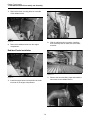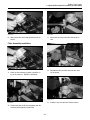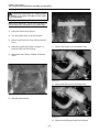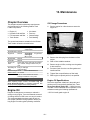
1
Service Manual
Rubber Track Loader
PT-50/60
Part Number: 2030-634
Printed (4-10)
Table of Contents
1. Product Safety
6. Chassis Disassembly and Assembly
Chapter Overview ................................................... 1-1
Basic Precautions ................................................... 1-1
Safety Labels ..................................................... 1-1
Personal Protective Equipment.......................... 1-1
Entering and Exiting ........................................... 1-2
Lifting ................................................................. 1-2
Hot Fluids and Parts .......................................... 1-2
Corrosion Inhibitor ............................................. 1-2
Batteries ............................................................ 1-2
Pressurized Items .............................................. 1-2
Repair ..................................................................... 1-3
Attachments ............................................................ 1-4
Machine Labels and Decals .................................... 1-4
Product ID Number ............................................ 1-4
Safety Label Examples ...................................... 1-4
Chapter Overview ................................................... 6-1
Personal Safety....................................................... 6-1
Machine Preparation ............................................... 6-1
Chassis Disassembly and Assembly
Procedures.............................................................. 6-1
Seat Removal and Installation ................................ 6-1
Seat Removal .................................................... 6-1
Seat Installation ................................................. 6-2
Fuel Sending Unit Removal and Installation ........... 6-2
Fuel Sending Unit Removal ............................... 6-3
Fuel Sending Unit Installation ............................ 6-3
7. Radiator/Oil Cooler Disassembly
and Assembly
Chapter Overview ................................................... 7-1
Personal Safety....................................................... 7-1
Machine Preparation ............................................... 7-1
Radiator/Oil Cooler Disassembly and Assembly
Procedures.............................................................. 7-1
Fan Guard Removal and Installation ....................... 7-1
Fan Guard Removal .......................................... 7-2
Fan Guard Installation ....................................... 7-2
Radiator/Cooler Removal and Installation ............... 7-2
Radiator/Cooler Removal .................................. 7-2
Radiator/Cooler Installation ............................... 7-4
2. Technical Specifications
PT-50 Specifications ............................................... 2-1
PT-60 Specifications ............................................... 2-2
3. System Diagrams
Chapter Overview ................................................... 3-1
Filtering and Cooling System .................................. 3-1
Auxiliary Circuit System .......................................... 3-2
Drive Loop System ................................................. 3-3
Electrical Attachment Outlet ................................... 3-3
8. Hydraulic Reservoir Disassembly
and Assembly
4. Machine Controls and Instrumentation
Chapter Overview ................................................... 4-1
Machine Controls .................................................... 4-1
Loader Control ................................................... 4-1
Drive Control ...................................................... 4-1
Throttle .............................................................. 4-1
Instrumentation ....................................................... 4-1
Switches .................................................................. 4-2
Chapter Overview ................................................... 8-1
Personal Safety....................................................... 8-1
Machine Preparation ............................................... 8-1
Hydraulic Reservoir Disassembly and Assembly
Procedures.............................................................. 8-1
Filter Element Removal and Installation .................. 8-1
Filter Assembly Removal and Installation ............... 8-1
Filter Assembly Removal ................................... 8-2
Filter Assembly Installation ................................ 8-3
Access Cover Removal and Installation .................. 8-4
Access Cover Assembly Removal ..................... 8-4
Access Cover Assembly Installation .................. 8-4
Reservoir Gauge Removal and Installation ............. 8-5
Reservoir Gauge Removal ................................ 8-5
Reservoir Gauge Installation ............................. 8-6
Suction Screen Removal and Installation ............... 8-6
Suction Screen Removal ................................... 8-6
Suction Screen Installation ................................ 8-7
Hydraulic Reservoir Cleaning Procedures ............. 8-7
Hydraulic Reservoir Cleaning ............................ 8-7
5. Operator Enclosure Disassembly
and Assembly
Chapter Overview ................................................... 5-1
Personal Safety ....................................................... 5-1
Machine Preparation ............................................... 5-1
Operator Enclosure Disassembly and Assembly
Procedures .............................................................. 5-1
Light Bar Removal and Installation.......................... 5-1
Light Bar Removal ............................................. 5-1
Light Bar Installation .......................................... 5-2
Ignition Switch Removal and Installation ................. 5-2
Ignition Switch Removal .................................... 5-2
Ignition Switch Installation ................................. 5-3
Gauge Removal and Installation ............................. 5-4
Gauge Removal ................................................. 5-4
Gauge Installation .............................................. 5-4
Lap Bar Gas Assist Spring Removal
and Installation ........................................................ 5-5
Lap Bar Gas Assist Spring Removal .................. 5-5
Lap Bar Gas Assist Spring Installation ............... 5-5
i
Rubber Track Loader
Table of Contents
9. Loader/Transmission Controls Disassembly
and Assembly
12. Loader Disassembly and Assembly
Chapter Overview ................................................. 12-1
Personal Safety..................................................... 12-1
Machine Preparation ............................................. 12-1
Loader Disassembly and Assembly Procedures .. 12-1
Lift Cylinder/Tilt Cylinder Removal
and Installation ...................................................... 12-1
Lift Cylinder/Tilt Cylinder Removal ................... 12-1
Lift Cylinder/Tilt Cylinder Installation ................ 12-3
Q/C Block Relief Valve Removal and Installation.. 12-3
Q/C Block Relief Valve Removal ..................... 12-3
Q/C Block Relief Valve Installation .................. 12-4
Chapter Overview ................................................... 9-1
Personal Safety ....................................................... 9-1
Machine Preparation ............................................... 9-1
Loader/Transmission Controls Disassembly and
Assembly Procedures ............................................. 9-1
Joystick Removal and Installation ........................... 9-1
Joystick Removal ............................................... 9-2
Joystick Installation ............................................ 9-3
Loader Float Magnet Removal and Installation ....... 9-3
Loader Float Magnet Removal........................... 9-3
Loader Float Magnet Installation........................ 9-4
Loader Valve Removal and Installation .................. 9-4
Loader Valve Removal ...................................... 9-4
Loader Valve Installation ................................... 9-6
Self Level Valve Removal and Installation ............. 9-6
13. Maintenance
Chapter Overview ................................................. 13-1
Maintenance Schedule ......................................... 13-1
Engine Oil ............................................................. 13-1
Oil Change Procedures ................................... 13-1
Engine Oil Specifications ................................. 13-1
Hydraulic Fluid and Filter ...................................... 13-2
Hydraulic Fluid and Filter Change
Procedures ...................................................... 13-2
Fuel/Water Separator ............................................ 13-3
Fuel Filter .............................................................. 13-3
Fuel Filter Change Procedures ........................ 13-3
Fuel Specifications .......................................... 13-3
Air Cleaner ............................................................ 13-3
Air Filter Change Procedures .......................... 13-3
Track Tension ....................................................... 13-4
Track Tension Adjustment Procedures ............ 13-4
Checking for Proper Track Adjustment ............ 13-4
Fuse Box ............................................................... 13-5
Grease Fittings...................................................... 13-5
Bleeding the Fuel System ..................................... 13-6
10. Transmission and Drive Disassembly
and Assembly
Chapter Overview ................................................. 10-1
Personal Safety ..................................................... 10-1
Machine Preparation ............................................. 10-1
Hydrostatic and Hydraulic Pump Disassembly
and Assembly Procedures .................................... 10-1
Auxiliary Gear Pump Removal and Installation ..... 10-1
Auxiliary Gear Pump Removal ......................... 10-1
Tandem Pump Removal and Installation .............. 10-3
Tandem Pump Removal .................................. 10-3
Tandem Pump Installation ............................... 10-4
Pump Drive Coupler Removal and Installation ...... 10-5
Pump Drive Coupler Removal ......................... 10-5
Pump Drive Coupler Installation ...................... 10-6
11. Undercarriage Disassembly and Assembly
14. Hydraulic Pressure Check & Adjustment
Chapter Overview ................................................. 11-1
Personal Safety ..................................................... 11-1
Machine Preparation ............................................. 11-1
Undercarriage Disassembly and Assembly
Procedures ............................................................ 11-1
Center Wheel Removal and Installation ................ 11-1
Wheel Removal ............................................... 11-2
End Wheel Removal and Installation .................... 11-3
End Wheel Removal ........................................ 11-3
End Wheel Installation ..................................... 11-3
Sprocket Roller Removal and Installation ............ 11-4
Track Removal and Installation ............................ 11-4
Track Removal................................................. 11-4
Track Installation.............................................. 11-4
Outboard Bearing Removal and Installation .......... 11-5
Bearing Removal ............................................. 11-5
Bearing Installation .......................................... 11-5
Drive Sprocket Removal and Installation .............. 11-6
Sprocket Removal ........................................... 11-6
Sprocket Installation ........................................ 11-6
Drive Motor Removal and Installation .................. 11-6
Drive Motor Removal ....................................... 11-6
Drive Motor Installation .................................... 11-6
Idler Wheel Hub Service Procedures .................... 11-7
Disassembly Procedure ................................... 11-7
Assembly Procedure ........................................ 11-9
Chapter Overview ................................................. 14-1
Personal Safety..................................................... 14-1
Machine Preparation ............................................. 14-1
Hydraulic Pressure Adjustment Procedures.......... 12-1
Charge Pressure check……………………………. 14-1
Charge Pressure Adjustment………………………14-1
Auxiliary Pressure Check & Adjustment…………..14-2
15. Troubleshooting
Chapter Overview ................................................. 15-1
Personal Safety..................................................... 15-1
Machine Preparation ............................................. 15-1
Preliminary Inspection ........................................... 15-1
Visual Inspection ............................................. 15-1
Troubleshooting Scenarios………………………...15-2
ii
1. Product Safety
Chapter Overview
This chapter contains product safety information for the
Terex PT-50/60 Rubber Track Loaders. Read and
understand all product safety information before
attempting to service any Rubber Track Loader.
Safety Alert Symbol
This symbol means: Attention!
Be alert! Your safety is
involved!
The safety alert symbol is used
to alert you to potential personal
injury hazards. Obey all safety messages that follow
this symbol to avoid possible injury or death.
This symbol is used as an attention-getting device
throughout this manual as well as on decals and labels
fixed to the machinery to assist in potential hazard
recognition and prevention.
Property or equipment damage warnings in this publication are identified by the signal word "NOTICE".
The person(s) in charge of servicing a Rubber Track
Loader may be unfamiliar with many of the systems on
the machine. This makes it especially important to use
caution when performing service tasks. Familiarize
yourself with the affected system(s) and components
before attempting any type of maintenance or service.
It is not possible to anticipate every potential hazard. The safety messages included in this document and displayed on the machine are not allinclusive. They are intended to make you aware of
potential risks and encourage a safe approach to
performing service work. If you use a tool, procedure, work method or operating technique that is
not specifically recommended by Terex, you must
satisfy yourself that it is safe for you and others.
You must also ensure that the machine will not be
damaged or be made unsafe by the operation,
lubrication, maintenance or repair procedures that
you choose.
Basic Precautions
NOTICE
Safety Labels
Safety labels have been included and are displayed in
various places throughout the machine to serve as
warnings of potentially dangerous conditions. Read
and understand all "Safety" labels on any Rubber
Track Loader before attempting to operate, maintain or
repair it. Replace any damaged, illegible or missing
labels immediately, prior to service.
“NOTICE” Indicates a hazardous situation which,
if not avoided, could result in property or equipment damage.
The word “Note” is used throughout this manual to
draw your attention to specific topics or to supplement
the information provided in that section.
Improper or incomplete maintenance/repair of a
Rubber Track Loader can be dangerous and
may result in machine damage, injury or death.
Personal Protective Equipment
Personal protection equipment is recommended when
performing maintenance or service on a machine.
Always wear appropriate protective equipment for
working conditions when working on or around the
machine. Loose clothing should not be worn and long
hair should be restrained. Wear hard hats, protective
face/eyewear, safety shoes and any other equipment
necessary to ensure your safety and the safety of others around you as you work.
Do not attempt to perform any type of repair or maintenance on a Rubber Track Loader until you have read
and fully understood both this manual and the
machine specific operation and maintenance manual.
Refer to the Operation and Maintenance manual for
instructions regarding proper machine operation and
maintenance techniques before operating or servicing
any Rubber Track Loader.
1-1
Rubber Track Loader
1. Product Safety
Entering and Exiting
Pressurized Items
Always use steps and handholds when entering or
exiting a Rubber Track Loader. Clean any mud or
debris from steps or work platforms before using them.
Always face the machine when using steps and handholds. When it is not possible to use the designed
entry/exit system, utilize ladders, scaffolds, or work
platforms to safely gain access to the machine.
1. Do not use hands or any other body part to check
for fluid leaks in the hydraulic system. Always use
a solid material like wood or metal to check for this
type of leak. Leaking fluid under pressure can penetrate body tissue. Fluid penetration can cause
serious injury and even death. If fluid is injected
into your skin, get treatment immediately. Seek
treatment from a doctor that is familiar with this
type of injury.
Lifting
Use a hoist when lifting components that weigh 50 lb
(23 kg) or more, to avoid back injury. Make sure all
chains, hooks, slings, etc., are in good condition and
are of the correct capacity. Be sure hooks are positioned correctly and equipped with a spring latch.
Lifting eyes are not to be side loaded during a lifting
operation.
2. Relieve pressure from the hydraulic system before
disconnecting or removing any lines, fittings or
related items. Do this by relaxing all hydraulic
actuators. If the lift arms are raised, make sure
they are securely braced. Be alert for possible
pressure release when disconnecting any device
from a pressurized system.
Hot Fluids and Components
Stay clear of hot components and system fluids of the
engine, exhaust, radiator/oil cooler and hydraulic
lines/tubes. Also, use caution when removing fill caps,
breathers and plugs on the machine. Hold a rag over
the cap or plug to prevent being sprayed or splashed
by liquids under pressure. Be especially careful if the
machine has been operated recently, fluids may still be
hot. To ensure your safety, allow the machine to cool
before attempting any service procedure that involves
hot fluids or components.
Corrosion Inhibitor
3. Lower the lift arms before performing any work on
the machine. If this cannot be done, make sure
they are securely braced to prevent them from
dropping unexpectedly during service.
4. Loose or damaged fuel, oil, hydraulic, lines, tubes
and hoses can cause fires. Do not bend or strike
high pressure lines or install ones that have been
bent or damaged. Check lines, tubes and hoses
carefully. See item 1 for precautions on checking
for fluid leaks.
5. Pressurized air or water can also cause injury.
When pressurized air or water is used for cleaning, wear a protective face shield, protective clothing, and protective shoes. The recommended maximum air pressure for cleaning purposes is 30 psi
(205 kPa). When using a pressure washer, keep in
mind that nozzle pressures are typically very high.
Generally, pressures are well above 2000 psi
(13790 kPa). Follow all recommended practices
provided by the pressure washer manufacturer.
Corrosion inhibitor contains alkali. Avoid contact with
eyes. Avoid prolonged or repeated contact with skin.
Do not take internally. In case of contact, wash skin
immediately with soap and water. For eyes, flush with
large amounts of water for at least 15 minutes. Call
Physician. Keep out of reach of children.
Batteries
Do not smoke when inspecting the battery electrolyte
level. Never disconnect any charging unit circuit or battery circuit cable from the battery when the charging
unit is operating. A spark can cause an explosion from
the flammable vapor mixture of hydrogen and oxygen
that is released from the electrolyte through the battery
outlets. Do not let electrolyte solution make contact
with skin or eyes. Electrolyte solution is an acid. In
case of contact, immediately wash skin with soap and
water. For eyes, flush with large amounts of water for
at least 15 minutes. Call Physician. Keep out of reach
of children.
1-2
Rubber Track Loader
1. Product Safety
8. Be prepared to stop an engine if it has been recently overhauled or the fuel system has been
recently serviced. If the engine has not been
assembled correctly, or if the fuel settings are not
correct, the engine can possibly overspeed and
cause bodily injury, death or property damage. Be
prepared to shut off the fuel and air supply to the
engine in order to stop the engine.
Repair
Accidental machine starting can cause injury
or even death to personnel working on a
Rubber Track Loader.
As a precaution, disconnect the battery cables from
the battery terminals, tape the battery clamps and
remove the key from the ignition switch prior to performing any service work on a Rubber Track Loader.
9. Be careful when removing cover plates. Gradually
back off the last two bolts or nuts located on opposite sides of the cover. Then, pry the cover loose
to relieve any spring or other pressure before
removing the last two nuts or bolts completely.
Place a “Do Not Operate” tag prominently on the
machine to inform personnel that the machine is
being serviced.
1. Disconnect the battery and discharge any capacitor before beginning work on a machine. Attach a
Do Not Operate tag in the cab to alert any operator that service is in progress.
10. Repairs requiring welding should be performed
only by personnel adequately trained and knowledgeable in welding procedures and with the guidance of appropriate reference information.
Determine the type of metal being welded and
select the correct welding procedure and filler
material to provide a weld that is as strong or
stronger than the original weld.
2. If possible, make all repairs with the machine
parked on a level, hard surface. Use blocks to prevent the machine from rolling while working on or
under the machine.
3. Do not work on or under any machine that is supported only by a hydraulic jack or hoist. Always
use some sort of mechanical support to ensure
that the machine will not fall. Terex jack stands
work well to support the machine while performing
maintenance or repair work.
11. Take precautions to avoid damaging wiring during
removal and installation operations. Carefully route
wires so that they will not contact sharp corners,
objects or hot surfaces during operation.
12. When performing service that requires the lift arms
to be in the raised position, always utilize the lift
arm brace located on the rear of the loader tower.
4. Make sure the work area around the machine is
safe and make yourself aware of any hazardous
conditions that may exist. If the engine needs to
be started inside an enclosure, make sure that the
engine’s exhaust is properly vented.
13. Relieve hydraulic system pressure by relaxing all
hydraulic actuators prior to attempting any
hydraulic maintenance or repair.
5. Be sure all protective devices including guards and
shields are properly installed and functioning correctly before beginning any service task. If a guard
or shield must be removed to perform the repair
work, use extra caution.
6. Always use the appropriate tools for the work to be
performed. Tools should be in good condition and
you should understand how to use them properly
before performing any service work.
7. When replacing fasteners, use parts of equivalent
grade and size. Do not use a lesser quality fastener if replacements are necessary.
14. Always tighten connections to the correct torque
specification. Make sure that all shields, clamps
and guards are installed correctly to avoid excessive heat, vibration or unwanted contact between
parts during operation. Shields that protect
exhaust components from oil spray in event of a
line, tube or seal failure must be correctly installed.
15. Do not operate a machine if any rotating part is
damaged or contacts other parts during operation.
Any high speed rotating component that has been
damaged or altered should be checked for balance
before reusing. Make sure all protective devices,
including guards and shields, are properly installed
and functioning correctly before starting the engine
or operating the machine.
1-3
Rubber Track Loader
1. Product Safety
Safety Label Examples
Attachments
Only use attachments that are recommended by Terex.
Examples of the labels and decals displayed on the
machine are shown on this page.
Make sure that all necessary guards and protective
equipment are in place and functioning prior to operating any attachment.
WARNING
Wear protective glasses and protective equipment as
required by conditions or as recommended in the
attachment’s operation manual.
Crush Hazard
Death or serious injury can result
from contact with moving lift arm or
attachment.
When replacement parts are required for your
machine, use only genuine Terex replacement
parts or parts that meet or exceed original
specifications including, but not limited to physical
dimensions, type, strength and material.
Keep clear of lift arms and
attachments.
WARNING
Installing lesser components can lead to premature
failures, product damage, personal injury or death.
CRUSH HAZARD
Contact with moving machine can
result in death or serious injury.
Keep clear of moving machine.
2030-593
WARNING
Ensure that all personnel are far enough away from
the work area so they will not be struck by flying objects.
Stay clear of the cutting edges, pinching surfaces or
crushing surfaces of the attachment while performing
any attachment maintenance, testing or adjustments.
Fall Hazard
Serious injury or death can result
from falling.
Use the provided access system when
entering or exiting the machine.
WARNING
Machine Labels and Decals
Labels and decals placed on the machine provide
safety information and operating instructions.
Familiarize yourself with the location and significance
of these labels to ensure your safety.
Crush Hazard
Death or serious injury can result
from contact with moving lift arm or
attachment.
Install lift arm brace prior to servicing.
WARNING
Product Identification Number
The Product Identification Number (PIN) is located on
the left side of the firewall next to the operator seat.
(figure 1-1). Always provide the PIN when contacting
the dealer about parts, service, warranty or accessories. No warranty claims will be processed unless
the PIN is provided.
Entanglement Hazard
Rotating parts can cause personal injury.
Keep away from fan and belt while the
engine is running. Stop engine before
servicing.
2030-600
WARNING
Burn Hazard
Hot fluid under pressure can scald.
Allow the machine to cool thoroughly
before opening.
2030-595
NOTICE
1-1
Fire Hazard
Flammable debris can collect near hot
components and lead to a fire.
1-4
Read Operator’s manual
Keep engine, exhaust and chassis
areas free of debris.
Rubber Track Loader
1. Product Safety
WARNING
WARNING
Fall Hazard
Crush Hazard
Falling can result in serious injury or death.
Rollover can crush and result in serious injury or death.
Explosion/Burn Hazard
Will cause death, burns or
blindness due to ignition of
explosive gasses or contact
with corrosive acid.
•
WARNING
WARNING
Fall Hazard
Falling from a machine can result in serious
injury or death.
WARNING
Rollover/Ejection Hazard
Serious injury or death can result.
Read Operator’s Manual
Read and understand the operator’s manual
and all safety signs prior to operating or
maintaining the machine.
No Riders
Carry loads low. Load unload and turn on
level ground. Travel on inclines with heaviest
end of machine uphill.
WARNING
•
Injection Hazard
Escaping fluid under pressure can
penetrate skin, causing serious injury.
Burn Hazard
Contact with hot surfaces can
cause burns.
Do not use the bucket/attachment as a work platform.
Fasten Seat Belt
Improper operation or maintenance can result in serious injury or death.
WARNING
DANGER
Relieve internal pressure before
disconnecting any line or fitting.
• Keep away from leaks or pinholes.
• Use cardboard to check for leaks.
Fluid injected into skin must be surgically removed within a few hours by a
doctor familiar with this type of injury
or gangrene will result.
1-5
•
•
Keep all flames/sparks
away!
No Smoking!
Read and understand
all manuals prior to
operation.
•
•
Do not touch hot
components!
Allow the machine to
cool thoroughly prior to
servicing.
1-6
2. Technical Specifications
PT-50 Specifications
Engine
−
−
−
−
−
−
Loader Valve
Model: Perkins 404D-22
Displacement: 2.2 liter
Gross horsepower: 50 hp, 37.3 kW
Torque: 105 lb-ft.143 Nm
Idle rpm: 2800 (high idle); 1175 (low idle)
Average water /thermostat temperature:
190°F, 87.8°C
− Model: Husko
− Relief pressure: 3000 psi (20,684 kPa)
− Pilot pressure required to move spools: 180220 psi (1241-1517 kPa)
Cooler
− Burst pressure: 400 psi (2757 kPa)
− Operating pressure: 250 psi (1724 kPa)
Transmission
− Bypass relief pressure: 80 psi (689 kPa)
− Model: A22 (38.5cc) tandem (Rexroth)
Drive pumps
− Hot oil sending unit: 225°F (107.2°C)
Critical Torque Specs
− Displacement: 2.349 in3/rev (38.5 cc/rev)
− Relief pressure: 5500 psi, 380 bar
− Flow: 28 gpm (106 lpm) @ 2800 rpm (high
idle)
Charge pump
− Transmission Mounting Bolts
o 85 ft-lb. w/Blue Loctite
− Drive Sprocket Drive Teeth Bolts
o 88 ft-lb. -Dry
− Center Bogie Wheel Retaining Nut
o 111 ft-lb. –Dry
− End Wheel Axle Retaining Nut
o 300 ft-lb. -Dry
− Drive Sprocket Lug Nut
o 129 ft-lb. -Dry
− Drive Motor Mounting Bolts
o 177 ft-lbs. -Dry
− Displacement: 1.098 in3/rev (18 cc/rev)
− Relief pressure: 400-450 psi
Drive Motors
− Model: Rexroth MCR 05C
− Displacement: 37.8 in3/rev (620 cc/rev)
Control Handles
− Model: 4TH6 (Rexroth)
Auxiliary Pump
− Make: Haldex-Barnes #180-2061
− Displacement: 1.343 in3/rev (22 cc/rev)
− Flow: 16.27 gpm (61.85 lpm) @ 2800 rpm
(high idle)
− Relief pressure: 3000 psi (20,684 kPa)
− Cooling/filtering: Auxiliary oil is filtered and
cooled at all times. In Auxiliary mode, the oil is
filtered after the attachment to protect the machine if the attachment motor fails or contaminants are introduced from the quick couplers.
2-1
Rubber Track Loader
2. Technical Specifications
PT-60 Specifications
Engine
−
−
−
−
−
−
Loader Valve
Model: Perkins 404D-22 T
Displacement: 2.2 liter
Gross horsepower: 60 hp, 44.7 kW
Torque: 140 lb-ft.190 Nm
Idle rpm: 2800 (high idle); 1175 (low idle)
Average water /thermostat temperature:
190°F, 87.8°C
− Model: Husco
− Relief pressure: 3000 psi (20,684 kPa)
− Pilot pressure required to move spools: 40320 psi (275.8-2206 kPa)
Cooler
− Burst pressure: 400 psi (2757 kPa)
− Operating pressure: 250 psi (1724 kPa)
Transmission
− Bypass relief pressure: 80 psi (689 kPa)
− Model: A22VG (38.5cc) tandem (Rexroth)
Drive pumps
− Hot oil sending unit: 225°F (107.2°C)
Critical Torque Specs
− Displacement: 2.349 in3/rev (38.5 cc/rev)
− Relief pressure: 5500 psi, 380 bar
− Flow: 28 gpm (106 lpm) @ 2800 rpm (high
idle)
Charge pump
− Transmission Mounting Bolts
o 85 ft-lb. (230 Nm) w/Blue Loctite
− Drive Sprocket Drive Teeth Bolts
o 105 ft-lb. (142 Nm) -Dry
− Wheel Axle Retaining Nut
o 300 ft-lb. (407 Nm)-Dry
− Drive Sprocket Lug Nut
o 129 ft-lb. (175 Nm)-Dry
− Drive Motor Mounting Bolts
o 177 ft-lbs. (480 Nm) -Dry
− Center Idler Wheel Mounting Bolts
o 105 ft-lbs. (142 Nm) -Dry
− Displacement: 1.098 in3/rev (18 cc/rev)
− Relief pressure: 400-450 psi ( 2758-3103 kpa)
Drive Motors
− Model: Rexroth MCR 5 (2-speed)
− Displacement: 50 in3/rev (820 cc/rev)
Control Handles
− Model: 4TH6 (Rexroth)
Auxiliary Pump
− Make: Haldex-Barnes #180-2061
− Displacement: 1.343 in3/rev (22 cc/rev)
− Flow: 17.4 gpm (65.9 lpm) @ 2800 rpm (high
idle)
− Relief pressure: 3000 psi (20,684 kPa)
− Cooling/filtering: Auxiliary oil is filtered and
cooled at all times. In Auxiliary mode, the oil is
filtered after the attachment to protect the machine if the attachment motor fails or contaminants are introduced from the quick couplers.
2-2
3. System Diagrams
Chapter Overview
Filtering and Cooling System
This chapter contains diagrams for the following
PT-50/60 systems.
The filtering and cooling system (Figure 3-1) contains
the following major components.
•
Filtering and cooling system
•
Hydraulic reservoir
•
Auxiliary circuit system
•
Radiator/oil cooler
•
Drive loop system
•
Loader valve
Figure 3-1
PT-50/60 Filtering and Cooling System
3-001
3-1
Rubber Track Loader
3. System Diagrams
Auxiliary Circuit System
The auxiliary circuit system (fig. 3-2) contains the
following major components.
•
Loader valve
•
Pilot control manifold
•
Auxiliary gear pump
•
Loader control joystick
Figure 3-2
PT-50/60 Auxiliary Circuit System
3-002
Self leveling (optional)
3-2
Rubber Track Loader
3. System Diagrams
Drive Loop System
The drive loop system (fig. 3-3) contains the
following major components.
•
Drive motors
•
Pilot control manifold
•
Drive control joystick
•
Tandem pump
Figure 3-3
PT-50/60 Drive Loop System
Input Portion (joystick)
3-003
tank
Output Portion (drive motors)
drive motor
tandem pump
(PT-60 2-spd)
tank
case drain
brake
pilot generation
block
drive motor
brake
(PT-60 2-spd)
3-3
case drain
Rubber Track Loader
3. System Diagrams
Electrical Attachment Outlet
Figure 3-4 PT-50/60 Electrical Attachment Outlet
3-4
4. Machine Controls and
Instrumentation
Chapter Overview
Instrumentation
This chapter contains an overview of the machine controls and instrumentation. For further information
regarding machine controls, instrumentation or operation, refer to the operation and maintenance manual
for your particular machine. Included here are illustrations of the following controls and instrumentation components and a description of their functions.
The Instruments (Figure 4-2) are positioned in the
overhead dash panel for ease of access and visibility
when seated inside the operator enclosure.
Instruments include the following components.
•
•
•
Machine Controls
Instrument Location and Function
Switch Location and Function
Machine Controls
(fig. 4-1)
There are three primary machine controls: lift arm control (2), drive control (1) and throttle (3).
(1)
(2)
(3)
(4)
(5)
Fuel Gauge
Tachometer (optional)
Engine Coolant Temp. Gauge (optional)
Hour Meter
Warning Indicator Display
• Engine Oil Pressure Warning Light
• Engine Temperature Warning Light
• Hydraulic Oil Temperature Warning Light
• Battery Voltage Warning Light
2
Lift Arm Control
3
1
5
4
The lift arm control (2) is a pilot operated joystick that
allows the operator to raise or lower the loader and
dump or curl the quick attach mechanism.
Drive Control
4-2
The drive control (1) is also a pilot operated joystick. It
allows the operator to change the direction and speed
of the machine.
NOTICE
Throttle
If the engine temperature, engine oil pressure or hydraulic oil
temperature lights illuminate or should the eng. coolant temp.
gauge read excessive temperatures during normal machine
operation, shut the machine down immediately (in a safe
location). Diagnose the problem and make any necessary
repairs before resuming normal operation.
The hand throttle (3) controls engine rpm.
NOTICE
2
If the battery low-voltage light should illuminate during operation, drive the machine to a suitable location and shut the
engine off. Diagnose the problem and make any needed
repairs before resuming operation.
1
The glow plug operation light illuminates only when the
key switch is turned to engine pre-heat, showing normal operation.
3
4-1
4-1
Rubber Track Loader
4. Machine Controls and Instrumentation
PT-50/60 Switches
1
2
3
4
5
4-3
The various switches (Figure 4-3) are positioned to
provide good access and visibility. The standard and
optional switches are listed below.
(1)
(2)
(3)
(4)
(5)
(6)
(7)
(8)
Work lights
Heater fan (optional)
Front wiper (optional)
Beacon light (optional)
Ignition, glow plug (pre-heat)
Auxiliary hydraulics
Bucket Positioning (optional)
Power Quick Attach (optional)
4-2
6
7
8
5. Operator Enclosure
Disassembly and Assembly
Chapter Overview
Operator Enclosure
Disassembly and Assembly
Procedures
This chapter provides disassembly and assembly
procedures for the operator enclosure assembly.
Disassembly and assembly procedures are provided
for the following operator enclosure components.
Personal Safety
Improper or incomplete maintenance/repair of a Rubber
Track Loader can be dangerous and may result in machine damage, injury or death.
Do not attempt to perform any type of repair or maintenance on a Rubber Track Loader until you have read and
fully understood the information in this manual.
•
Light Bar
•
Ignition Switch
•
Gauges
•
Lap Bar Gas Assist Spring
Note: Procedures are provided for only those operator
enclosure components listed above. However, information
for removal and installation of other operator enclosure
components can be obtained from the machine specific
parts manual.
Refer to the Operation and Maintenance manual for instructions regarding proper machine operation techniques
before operating any Rubber Track Loader.
Prior to performing any type of service work on a
Rubber Track Loader, read and understand Chapter
1 (Product Safety) for personal safety information.
Light Bar Removal and
Installation
Machine Preparation
The tools required for light bar console removal and
installation are listed in Table 5-1. Use manufacturer
recommended tools whenever possible.
Accidental machine starting can cause injury or
death to personnel working on a Rubber Track
Loader.
Table 5-1
As a precaution, disconnect the battery cables from
the battery terminals, tape the battery clamps and
remove the key from the ignition switch prior to performing any service work on a Rubber Track Loader.
Required Tools
Combination Wrench
Light Bar Removal
Place a “Do Not Operate” tag prominently on the
machine to inform personnel that the machine is being worked on.
Figure 5-1
1. Loosen the two cap screws that attach the light
bar to the cab frame.
5-1
Rubber Track Loader
5. Operator Enclosure Disassembly and Assembly
Light Bar Installation
Figure 5-2
2. Carefully lower the light bar with the wire harness attached.
Figure 5-5
1. Carefully position the light bar, without pinching
the wiring harness against the cab roof.
Figure 5-3
3. View of light bar interior components. Interior
components are now accessible for servicing.
Figure 5-6
2. Secure the light bar to the cab roof with the two
capscrews
Ignition Switch Removal and
Installation
The tools required for ignition switch removal and
installation are listed in Table 5-2. Use manufacturer-recommended tools whenever possible.
Figure 5-4
4. View of dome light. If removal is required, simply
insert a lever (blade-type screw driver) at opposite end of switch in pry-pocket, and gently pry
the light assembly out of the light bar.
Table 5-2
Required Tools
Combination Wrench
Ignition Switch Removal
1. Lower the light bar. Refer to Chapter 5. Light Bar
Removal procedure.
5-2
Rubber Track Loader
5. Operator Enclosure Disassembly and Assembly
Ignition Switch Installation
Remove Nut
Figure 5-7
Figure 5-10
2. Remove the nut that secures the ignition switch
to the dash panel.
1. Insert the ignition switch from the rear of the
dash panel.
Install Nut
Figure 5-8
Figure 5-11
3. Pull the ignition switch out from the rear of the
dash panel.
2. Install the nut that secures the ignition switch to
the dash panel.
Figure 5-9
Figure 5-12
4. Unplug the ignition switch connector.
3. Plug in the ignition switch connector.
5-3
Rubber Track Loader
5. Operator Enclosure Disassembly and Assembly
4. Install the light bar. Refer to Chapter 5. Light Bar
Installation procedure.
Gauge Removal and Installation
The tools required for gauge removal and installation
are listed in Table 5-3. Use manufacturerrecommended tools whenever possible.
Table 5-3
Required Tools
Figure 5-15
Combination wrench
4. Pull the gauge out from the front of the dash
panel.
Gauge Removal
Gauge Installation
1. Lower the light bar. Refer to Chapter 5. Light Bar
Removal procedure.
Figure 5-16
Figure 5-13
2. Disconnect the connector from the gauge.
1. Insert the gauge from the front of the dash panel.
Figure 5-14
Figure 5-17
3. Remove the two nuts that secure the gauge to
the retaining bracket.
2. Install the two nuts that secure the gauge to the
retaining bracket.
5-4
Rubber Track Loader
5. Operator Enclosure Disassembly and Assembly
Remove
Retaining Clip
Figure 5-18
Figure 5-20
3. Reconnect the gauge connector.
2. Using a small screwdriver, remove the retaining
clip from each end of the gas assist spring.
4. Install the light bar. Refer to Chapter 5. Light Bar
Installation procedure.
Lap Bar Gas Assist Spring
Removal and Installation
The tools required for gas assist spring removal and
installation are listed in Table 5-4. Use manufacturer-recommended tools whenever possible.
Table 5-4
Required Tools
Figure 5-21
Screwdriver
3. Remove the gas assist spring by pulling both
ends out from the ball joints.
Lap Bar Gas Assist Spring Removal
Lap Bar Gas Assist Spring Installation
Gas Assist
Spring
Gas Assist
Spring Location
Raise Lap Bar
(Shown in Down
Position)
Raise Lap Bar
(Shown in Down
Position)
Figure 5-19
1. Put the lap bar in the UP position to relieve tension on the lap bar gas assist spring.
Figure 5-22
1. Put the lap bar in the UP position to minimize
tension on the lap bar gas assist spring during
installation.
5-5
Rubber Track Loader
5. Operator Enclosure Disassembly and Assembly
Install Ends on
Ball Joints
Figure 5-23
2. Install the ends of the lap bar gas assist spring
onto the ball joints.
Insert
Retaining Clip
Figure 5-24
3. Slide the retaining clip on to each end of the gas
assist spring.
5-6
6. Seat & Fuel Sender Disassembly and Assembly
Chapter Overview
Chassis Disassembly and
Assembly Procedures
This chapter provides disassembly and assembly
procedures for the chassis assembly.
Disassembly and assembly procedures are provided
for the following chassis components.
Personal Safety
•
Seat
Improper or incomplete maintenance/repair of a Rubber
Track Loader can be dangerous and may result in machine damage, injury or death.
•
Fuel Sending Unit
•
Fuel Sending Unit Hose
Do not attempt to perform any type of repair or maintenance on a Rubber Track Loader until you have read and
fully understood the information in this manual.
•
In-Tank Weight
Note: Procedures are provided for only those chassis
components listed above. However, information for removal and installation of other chassis components can be
obtained from the exploded view illustration provided in
the Rubber Track Loader Parts manual.
Refer to the Operation and Maintenance manual for instructions regarding proper machine operation techniques
before operating any Rubber Track Loader.
Prior to performing any type of service work on a
Rubber Track Loader, read and understand Chapter
1 (Product Safety) for personal safety information.
Seat Removal and Installation
The tools required for seat removal and installation
are listed in Table 6-1. Use manufacturerrecommended tools whenever possible.
Machine Preparation
Accidental machine starting can cause injury or
death to personnel working on a Rubber Track
Loader.
Table 6-1
Required Tools
As a precaution, disconnect the battery cables from
the battery terminals, tape the battery clamps and
remove the key from the ignition switch prior to performing any service work on a Rubber Track Loader.
Socket Wrench
Seat Removal
Place a “Do Not Operate” tag prominently on the
machine to inform personnel that the machine is being worked on.
Remove Seat Bolts
Figure 6-1
1. Remove the four nuts that fasten the seat
mounts to the frame.
6-1
Rubber Track Loader
6. Chassis Disassembly and Assembly
Unplug
Connector
Plug in the Connector
Figure 6-2
Figure 6-5
2. Tilt the seat forward and reach behind the seat
to unplug the seat switch wiring harness.
2. Tilt the seat forward and reach behind the seat
to plug in the seat switch connector
Note: The machine will not operate unless the seat switch
connector is plugged in.
insert Seat Bolts
Figure 6-3
3. Remove the seat. Be careful not to scratch the
control panel or sides of the cab.
Figure 6-6
Seat Installation
3. Position the seat so the holes in the seat mounts
are aligned with the bolts in the frame. Install the
four seat mount nuts and washers.
Fuel-Sending Unit Removal
and Installation
The tools required for fuel sending unit removal and
installation are listed in Table 6-2. Use manufacturer-recommended tools whenever possible.
Table 6-2
Required Tools
Figure 6-4
Screwdriver
Combination Wrench
Socket Wrench
1. With the seat mounts attached, place the seat in
the cab. Be careful not to scratch the control
panel or sides of the cab.
6-2
Rubber Track Loader
6. Chassis Disassembly and Assembly
4. Remove the fuel-sending unit. Be careful not to
damage the float mechanism when pulling it
through the opening in the fuel tank.
Fuel Sending Unit Removal
1. Remove the seat. Refer to Chapter 6. Seat Removal procedure.
2. Pump fuel from the tank until there is no fuel
remaining above the sending unit.
Collect and contain liquids in a suitable container. Dispose of all liquids according to local regulations and mandates.
Figure 6-9
5. The fuel pickup line will also come out with the
fuel-sending unit.
Fuel Sending Unit Installation
Figure 6-7
3. Remove the hoses and wires from the fuelsending unit, then remove the screws that fasten
the unit to the tank. Mark the wires and hoses.
Note: If the fuel sending unit wires are crossed, the fuel
gauge will not work. If the hoses are crossed, the engine
will not run.
Figure 6-10
1. Insert the fuel pickup line into the fuel tank opening. The pickup line is attached to the fuelsending unit.
Note: The weight on the end of the fuel pickup line must
rest on the bottom of the tank for proper operation.
2. Insert the fuel sending unit float mechanism into
the fuel tank opening. Be careful not to damage
the float when pushing it through the opening.
Figure 6-8
6-3
Rubber Track Loader
6. Chassis Disassembly and Assembly
Note: Make sure that the wire on the sending unit is not
bent and the fuel pickup line does not interfere with the
movement of the float.
3. Connect the hoses and wires to the fuel-sending
unit, and then install the screws that fasten the
unit to the tank.
Note: Be careful not to cross the wires or hoses. If the
fuel sending unit wires are crossed, the fuel gauge will not
work. If the hoses are crossed, the engine will not run.
4. Install the seat. Refer to Chapter 6. Seat Installation procedure.
6-4
7. Radiator/Oil Cooler
Disassembly and Assembly
Chapter Overview
Radiator/Oil Cooler
Disassembly and Assembly
Procedures
This chapter provides disassembly and assembly
procedures for the radiator/oil cooler assembly. Adjustment procedures are also included for selected
radiator/oil cooler components.
Disassembly and assembly procedures are provided
for the following radiator/oil cooler components.
Personal Safety
Improper or incomplete maintenance/repair of a Rubber
Track Loader can be dangerous and may result in machine damage, injury or death.
•
Fan Guard
•
Radiator/Cooler
Note: Procedures are provided for only those radiator/oil
cooler components listed above. However, information for
removal and installation of other radiator/oil cooler components can be obtained from the machine specific parts
manual.
Do not attempt to perform any type of repair or maintenance on a Rubber Track Loader until you have read and
fully understood the information in this manual.
Refer to the Operation and Maintenance manual for instructions regarding proper machine operation techniques
before operating any Rubber Track Loader.
Note: Refer to Figure 3-1 for an overview of the filtering
and cooling system.
Prior to performing any type of service work on a
Rubber Track Loader, read and understand Chapter
1 (Product Safety) for personal safety information.
Fan Guard Removal and Installation
Machine Preparation
Accidental machine starting can cause injury or
death to personnel working on a Rubber Track
Loader.
The tools required for fan guard removal and installations are listed in Table 7-1. Use manufacturerrecommended tools whenever possible.
As a precaution, disconnect the battery cables from
the battery terminals, tape the battery clamps and
remove the key from the ignition switch prior to performing any service work on a Rubber Track Loader.
Table 7-1
Required Tools
Combination Wrench
Place a “Do Not Operate” tag prominently on the
machine to inform personnel that the machine is being worked on.
7-1
Rubber Track Loader
7. Radiator/Oil Cooler Disassembly and Assembly
Fan Guard Removal
Radiator/Cooler Removal and
Installation
The tools required for radiator/cooler removal and
installations are listed in Table 7-2. Use manufacturer-recommended tools whenever possible.
Table 7-2
Required Tools
Combination Wrench
Socket Wrench
Screwdriver
Radiator/Cooler Removal
Figure 7-1
1. Remove the bolts that secure the fan guard to
the fan shroud.
Hot oil can cause personal injury. Make sure the
oil is cool before removing any components or lines.
2. Remove the fan guard from the engine compartment.
Remove the oil filler cap only when the engine is
stopped and has been allowed to cool thoroughly.
Fan Guard Installation
Personal injury can result from hot coolant,
steam and alkali.
1. Position the fan guard over the fan and against
the fan shroud.
At operating temperature, engine coolant is hot and
under pressure. The radiator and hoses contain hot
coolant and steam. Allow the machine to cool thoroughly prior to performing service or repair procedures to avoid burns.
2. Install the capscrews that secure the fan guard
to the fan guard mounts.
Remove the filler cap slowly to relieve pressure only
when the engine is stopped and the machine has been
allowed to cool thoroughly.
Cooling system conditioner contains alkali. Avoid
contact with skin and eyes.
Collect and contain liquids in a suitable container. Dispose of all liquids according to local regulations and mandates.
1. Drain the hydraulic fluid. Refer to Chapter 13.
Hydraulic Fluid and Filter Change.
7-2
Rubber Track Loader
7. Radiator/Oil Cooler Disassembly and Assembly
Figure 7-5
Figure 7-2
5. Remove the upper hose from the radiator section. Cap the hose and fitting.
2. Drain the coolant using the petcock on the bottom of the radiator.
Figure 7-6
Figure 7-3
6. Remove the lower hose from the radiator section. Cap the hose and fitting.
3. Remove the lower hose from the oil cooler section. Cap the hose and fitting.
Remove Bolts
Remove
Hose
Figure 7-4
4. Remove the upper hose from the oil cooler section. Cap the hose and fitting.
Figure 7-7
7-3
Rubber Track Loader
7. Radiator/Oil Cooler Disassembly and Assembly
7. Remove the three mounting bolts on each side
of the radiator/cooler.
Install Bolts
Figure 7-10
Figure 7-8
2. With the radiator/cooler in position, install the
three mounting bolts on each side of the radiator/cooler.
8. Remove the radiator/cooler from the engine
compartment.
Radiator/Cooler Installation
Figure 7-11
3. Remove the hose and fitting caps and install the
lower hose on the radiator section.
Figure 7-9
1. Install the engine shroud, and position the radiator/cooler in the engine compartment.
Figure 7-12
7-4
Rubber Track Loader
7. Radiator/Oil Cooler Disassembly and Assembly
4. Remove the hose and fitting caps and install the
upper hose on the radiator section.
Install
Hose
Figure 7-13
5. Remove the hose and fitting caps and install the
upper hose on the oil cooler section.
Figure 7-14
6. Remove the hose and fitting caps and install the
lower hose on the oil cooler section.
7. Close the petcock and fill the radiator with coolant and the hydraulic reservoir with oil.
7-5
8. Hydraulic Reservoir
Disassembly and Assembly
Chapter Overview
Hydraulic Reservoir
Disassembly and Assembly
Procedures
This chapter provides disassembly and assembly
procedures for the hydraulic reservoir assembly.
Cleaning procedures are also included for the hydraulic reservoir.
Disassembly and assembly procedures are provided
for the following hydraulic reservoir components.
Personal Safety
Improper or incomplete maintenance/repair of a Rubber
Track Loader can be dangerous and may result in machine damage, injury or death.
•
Filter Element
•
Filter Assembly
•
Filler Cap Assembly
•
Access Cover Assembly
Do not attempt to perform any type of repair or maintenance on a Rubber Track Loader until you have read and
fully understood the information in this manual.
•
Reservoir Gauge
•
Suction Screen
Refer to the Operation and Maintenance manual for instructions regarding proper machine operation techniques
before operating any Rubber Track Loader.
Note: Procedures are provided for only those hydraulic
reservoir components listed above. However, information
for removal and installation of other hydraulic reservoir
components can be obtained from the Rubber Track
Loader Parts List manual.
Prior to performing any type of service work on a
Rubber Track Loader, read and understand Chapter
1 (Product Safety) for personal safety information.
Note: Refer to Figure 3-1 for an overview of the filtering
and cooling system.
Machine Preparation
Accidental machine starting can cause injury or
death to personnel working on a Rubber Track
Loader.
Filter Element Removal and
Installation
As a precaution, disconnect the battery cables from
the battery terminals, tape the battery clamps and
remove the key from the ignition switch prior to performing any service work on a Rubber Track Loader.
Refer to Chapter 13. Maintenance – Hydraulic Fluid
and Filter for removal and installation of the filter.
Filter Assembly Removal and
Installation
Place a “Do Not Operate” tag prominently on the
machine to inform personnel that the machine is being worked on.
The tools required for filter assembly removal and
installation are listed in Table 8-1. Use manufacturer-recommended tools whenever possible.
Table 8-1
Required Tools
Combination/Socket Wrenches
Needle Nose Pliers
8-1
Rubber Track Loader
8. Hydraulic Reservoir Disassembly and Assembly
Filter Assembly Removal
Hot oil can cause personal injury. Make sure the
oil is cool before removing any components or lines.
Remove the oil filler cap only when the engine is
stopped and the machine has been allowed to cool
thoroughly
Note: During disassembly, cap all hoses and fittings to
prevent fluid loss and contamination of the system fluids.
Figure 8-3
3. Remove the filter from the reservoir as shown.
Figure 8-1
1. Remove the screws securing the cover to the
filter assembly.
Figure 8-4
4. Disconnect the hose from the filter assembly.
Figure 8-2
2. Remove the cap from the filter assembly as
shown.
Figure 8-5
5. Remove the bolts securing the filter head assembly to the reservoir.
8-2
Rubber Track Loader
8. Hydraulic Reservoir Disassembly and Assembly
Figure 8-6
Figure 8-9
6. Remove the filter head and gasket from the reservoir.
3. Reconnect the hose to the filter head and secure.
Filter Assembly Installation
Figure 8-10
Figure 8-7
4. Reinstall the filter and filter tube into the reservoir as shown.
1. Place the filter assembly gasket in position on
top of the reservoir. Replace if damaged.
Figure 8-11
5. Install the cap onto the filter head as shown.
Figure 8-8
2. Position the filter head onto the gasket with the
mounting holes aligned, install bolts.
8-3
Rubber Track Loader
8. Hydraulic Reservoir Disassembly and Assembly
1. Slightly loosen the access cover bolt to separate
the upper cap from the oval-shaped clamping
disk on the underside of the assembly. This will
allow the assembly to be removed. Do not remove the bolt entirely or the oval-shaped clamp
will fall into the reservoir.
Figure 8-12
6. Install the cap bolts and tighten to secure.
Access Cover Removal and
Installation
The tools required for access cover removal and
installation are listed in Table 8-2. Use manufacturer-recommended tools whenever possible.
Figure 8-14
2. Remove the access cover assembly from the
reservoir.
Table 8-2
Required Tools
Access Cover Assembly Installation
Combination Wrench
Access Cover Assembly Removal
Hot oil can cause personal injury. Make sure the
oil is cool before removing any components or lines.
Remove the oil filler cap only when the engine is
stopped and the machine has been allowed to cool
thoroughly
Figure 8-15
1. Insert the access cover assembly with the
clamping disk extending completely through the
opening in the top of the reservoir and into the
tank.
Figure 8-13
8-4
Rubber Track Loader
8. Hydraulic Reservoir Disassembly and Assembly
Figure 8-16
Figure 8-17
2. Tighten the access cover bolt.
3. View of hydraulic reservoir with filter assembly
removed.
Reservoir Gauge Removal and
Installation
The tools required for reservoir gauge removal and
installation are listed in Table 8-3. Use manufacturer-recommended tools whenever possible.
Table 8-3
Required Tools
Combination Wrenches
Reservoir Gauge Removal
Figure 8-18
4. Reach inside the reservoir and remove the two
nuts that fasten the reservoir gauge to the reservoir.
Hot oil can cause personal injury. Make sure the
oil is cool before removing any components or lines.
Remove the oil filler cap only when the engine is
stopped and the machine has been allowed to cool
thoroughly
Collect and contain liquids in a suitable container. Dispose of all liquids according to local regulations and mandates.
Remove Reservoir Gauge
with Mounting
Bolts/Washers
Note: During disassembly, cap all hoses and fittings to
prevent fluid loss and contamination of the system fluids.
1. Drain the hydraulic fluid. Refer to Chapter 13.
Hydraulic Fluid and Filter Change.
Figure 8-19
5.
2. Remove the filter assembly. Refer to Chapter 8.
Filter Assembly Removal.
8-5
Pull the reservoir gauge and the two mounting
bolts/washers off the reservoir. DO NOT misplace the rubber washers or the reservoir will
leak.
Rubber Track Loader
8. Hydraulic Reservoir Disassembly and Assembly
Reservoir Gauge Installation
Suction Screen Removal
Hot oil can cause personal injury. Make sure the
oil is cool before removing any components or lines.
Remove the oil filler cap only when the engine is
stopped and the machine has been allowed to cool
thoroughly
Insert Reservoir Gauge
with Mounting
Bolts/Washers
Collect and contain liquids in a suitable container. Dispose of all liquids according to local regulations and mandates.
Figure 8-20
Note: It is normally not necessary to replace the suction
screen unless there has been a catastrophic failure and
there is debris in the reservoir.
1. Install the reservoir gauge in the reservoir using
the two mounting bolts/washers.
1. Drain the hydraulic fluid. Refer to Chapter 13.
Hydraulic Fluid and Filter Change.
2. Remove the access cover assembly. Refer to
Chapter 8. Access Cover Assembly Removal.
Figure 8-2113
2. Reach inside the reservoir and install the two
nuts that secure the reservoir gauge to the reservoir.
3. Install the filter assembly. Refer to Chapter 8.
Filter Assembly Installation.
4. Add manufacturer-approved hydraulic fluid.
Figure 8-22
Suction Screen Removal and
Installation
3. With a magnet centered in an absorbent rag,
thoroughly clean the interior of the reservoir to
prevent any debris from entering the system
when you remove the suction filter.
The tools required for suction screen removal and
installation are listed in Table 8-4. Use manufacturer-recommended tools whenever possible.
Table 8-4
Required Tools
Combination Wrench
8-6
Rubber Track Loader
8. Hydraulic Reservoir Disassembly and Assembly
Hydraulic Reservoir Cleaning
Procedures
Cleaning procedures are provided for the following
hydraulic reservoir components.
•
Hydraulic Reservoir
Hydraulic Reservoir Cleaning
The tools required for hydraulic reservoir cleaning
are listed in Table 8-5. Use manufacturerrecommended tools whenever possible.
Figure 8-23
Table 8-5
4. Reach inside the reservoir and unscrew the suction screen. Remove the suction screen from the
reservoir.
Tool Name
Combination Wrench
Suction Screen Installation
Hot oil can cause personal injury. Make sure the
oil is cool before removing any components or lines.
Remove the oil filler cap only when the engine is
stopped and the machine has been allowed to cool
thoroughly
Collect and contain liquids in a suitable container. Dispose of all liquids according to local regulations and mandates.
1. Drain the hydraulic fluid. Refer to Chapter 13.
Hydraulic Fluid and Filter Change.
Figure 8-24
2. Remove the access cover assembly. Refer to
Chapter 8. Access Cover Assembly Removal.
1. Insert the suction screen in the reservoir through
the access cover opening.
3. Thoroughly wipe out the interior of the hydraulic
reservoir with a magnet and a clean rag.
2. Reach inside the reservoir and screw the suction
screen into the bottom of the reservoir.
4. Install the access cover assembly. Refer to
Chapter 8. Access Cover Assembly Installation.
3. Install the access cover assembly. Refer to
Chapter 8. Access Cover Assembly Installation.
5. Add manufacturer-approved hydraulic fluid.
4. Add manufacturer-approved hydraulic fluid.
8-7
9. Loader/Transmission Controls
Disassembly and Assembly
Chapter Overview
Loader/Transmission Controls
Disassembly and Assembly
Procedures
This chapter provides disassembly and assembly procedures for the loader and transmission controls.
Personal Safety
Improper or incomplete maintenance/repair of a Rubber
Track Loader can be dangerous and may result in ma-chine
damage, injury or death.
Do not attempt to perform any type of repair or mainten-ance
on a Rubber Track Loader until you have read and fully
understood the information in this manual. Refer to the
Operation and Maintenance manual for in-structions regarding proper machine operation techniques before operating
any Rubber Track Loader.
Prior to performing any type of service work on a Rubber
Track Loader, read and understand Chapter 1 (Product
Safety) for personal safety information.
Machine Preparation
Accidental machine starting can cause injury or death to personnel working on a Rubber Track Loader.
As a precaution, disconnect the battery cables from the battery terminals, tape the battery clamps and remove the key
from the ignition switch prior to per-forming any service work
on a Rubber Track Loader.
Disassembly and assembly procedures are provided
for the following loader/transmission control components.
• Drive Control Joystick
• Loader Control Joystick
• Loader Float Magnet
• Loader Valve
• Self Level Valve
Note: Procedures are provided for only those
loader/transmission control components listed above.
However, information for removal and installation of
other loader/transmission control components can be
obtained from the Rubber Track Loader Parts manual.
Note: Refer to Figure 3-2 for an overview of the auxiliary circuit system and Figure 3-3 for an overview of
the drive loop system.
Loader Control Joystick/Drive
Control Joystick Removal and
Installation
Place a “Do Not Operate” tag prominently on the machine to
inform personnel that the machine is be-ing worked on.
There are two joysticks that control the operation of the
machine: a drive control joystick and a loader control
joystick.
Drive Control Joystick Operation – The left-hand
joystick controls the speed and direction of the machine. The further the joystick is pushed, the faster the
machine travels. The joystick operates on hy-draulic
charge pressure. When the joystick is moved, oil is
sent to the hydrostatic transmission. The transmission
then delivers oil, in the correct amount, to the drive
motors.
9-1
Rubber Track Loader
9. Loader/Transmission Controls
Loader Control Joystick Operation – The right-hand
joystick controls the loader arm and the at-tachment tilt
cylinder. It allows the operator to raise, lower and pivot
the attachment. The joystick operates on hydraulic
charge pressure.
The loader control also has a float position, which is
activated by moving the joystick completely forward
until it is held in detent. The joystick is held in the forward float position by an electromagnet.
The tools required for loader/drive control joystick
removal and installation are listed in Table 9 1. Use
manufacturer recommended tools whenever possible.
Figure 9-1
5. Remove the various screws holding the plastic
side consoles to the cab enclosure as shown.
Table 9-1
Required Tools
Combination/Socket Wrenches
Screwdriver (phillips)
Loader Control Joystick/Drive Control
Joystick Removal
Note: The procedures for removing both joystick controls are nearly identical, as a result, only the right control joystick procedure is described below.
Note: During disassembly, cap and plug all hoses and
fittings to prevent fluid loss and contamination of the
system fluids.
Figure 9-2
6. Pivot the panel away from the joystick, then lift and
remove it from the machine.
Relax all hydraulic circuits/controls and make
sure the oil is cool before disconnecting any
component or line from the system.
Pressurized and or hot hydraulic fluid can cause personal injury.
1. Remove the seat from the machine according to
the procedure in chapter 6, seat removal.
2. Lower the lift arms to the ground.
Figure 9-3
3. Turn the ignition switch to the OFF position.
7. Remove the three nuts securing the joystick mount
to the cab enclosure from the outside of the
machine.
4. Relax all hydraulic circuits.
9-2
Rubber Track Loader
9. Loader/Transmission Controls
Note: If it is neccessary to remove the left joystick on a
machine equipped with a heater, you must disconnect
the (cool) heater lines at the heater unit in order to
remove the side panel. Cap and plug hoses and ports
to minimize coolant loss.
Loader Float Magnet Removal and
Installation
Figure 9-4
8. Pull the joystick away from the cab wall as shown.
The tools required for loader float magnet removal and
installation are listed in Table 9-2. Use manufacturer
recommended tools whenever possible.
Table 9-2
Required Tools
Allen (hex) Wrenches
Combination Wrenches
Screwdriver
Loader Float Magnet Removal
Figure 9-5
9. The hydraulic hoses are now accessible. Label
them and the ports they connect to to aid during
reassembly, then disconnect them and cap and
plug the openings to prevent spills.
Figure 9-7
1. Remove the zip tie securing the lower portion of
the joystick boot to the joystick as shown.
Remove
Figure 9-6
10. Disconnect the electrical connections shown to
free the joystick from the machine, then remove.
11. Reverse the removal procedure to reinstall the joy
stick. Take care to ensure all connections are to
the appropriate ports on the joystick and that they
are tight and leak free.
Figure 9-8
2. Lift the boot to expose the magnet and joystick
mounting bolts. Remove the joystick mounting
bolts to allow the joystick to be moved upward
within the bracket.
9-3
Rubber Track Loader
9. Loader/Transmission Controls
Loader Valve Removal and
Installation
The tools required for loader valve removal and in-stallation are listed in Table 9 3. Use manufacturer-recommended tools whenever possible.
Table 9-3
Required Tools
Combination Wrenches
Figure 9-9
Loader Valve Removal
Hot oil can cause personal injury. Lower all
attach-ments and make sure the oil is cool
before removing any components or lines.
3. Use an allen (hex) wrench to remove the bolt
securing the magnet to the joystick.
Remove the oil filler cap only when the engine is
stopped and the filler cap is cool enough to touch
with your hands.
Collect and contain liquids in a suitable container. Dispose of all liquids according to local
regulations and mandates.
Note: During disassembly, cap all hoses and fittings to
prevent fluid loss and contamination of the system fluids.
Figure 9-10
4. Lift the joystick out of the mounting bracket slightly
to allow the magnet connector to pass between
them, then remove the magnet.
5. To install the float magnet, reverse the removal
procedure.
1. Lower the lift arms to the ground.
2. Turn the engine start switch to the OFF position.
3. Relieve hydraulic pressure from the auxiliary cir
cuit.
4. Drain the hydraulic fluid. Refer to Chapter 13.
Hydraulic Fluid and Filter Change.
9-4
Rubber Track Loader
9. Loader/Transmission Controls
Figure 9-11
Figure 9-14
5. Disconnect the gas springs, then remove the bolts
securing the hood as shown to allow for removal.
8. Carefully remove the rear valance from the
machine to allow access to the loader valve.
Loader Valve
Figure 9-12
Figure 9-15
6. Carefully remove the hood from the machine and
set it aside.
9. Locate the loader valve on the side of the
hydraulic reservoir.
Disconnect
Figure 9-13
Figure 9-16
7. Remove the bolts securing the rear valance panel
to the chassis to allow for removal.
10. Disconnect all of the tubes from the loader valve.
Cap and plug all openings to prevent fluid loss.
9-5
Rubber Track Loader
9. Loader/Transmission Controls
Disconnect
Figure 9-18
11. Disconnect the hoses from the rear and side of the
loader valve. Cap and plug all openings to prevent
fluid loss.
Figure 9-19
Self Level Valve Removal and
Installation
The tools required for loader valve removal and installation are listed in Table 9-4. Use manufacturer recommended tools whenever possible.
Table 9-4
Required Tools
Remove
Combination Wrenches
Hot oil can cause personal injury. Lower all
attach-ments and make sure the oil is cool
before removing any components or lines.
Figure 9-19
Remove the oil filler cap only when the engine is
stopped and the filler cap is cool enough to touch
with your hands.
12. Remove the nuts securing the valve to the reser
voir as shown, then remove the valve from the
machine.
Collect and contain liquids in a suitable container. Dispose of all liquids according to local
regulations and mandates.
13. To reinstall, reverse the removal procedure.
14. Once all components have been reinstalled and
are secure, add manufacturer approved hydraulic
fluid until full mark is reached on the level gauge.
Note: During disassembly, cap all hoses and fittings to
prevent fluid loss and contamination of the system fluids.
Note: To eliminate trapped air from the system, activate all hydralic circuits and run machine through its
paces including moving the lift arms up and down, curling and tilting the Q/A, driving forward and in reverse,
and activating the auxiliary circuit. Then, check
hydraulic fluid level and add as required to reach full
mark.
1. Lower the lift arms to the ground.
2. Disconnect all tubes and wire harness from the
self level valve.
3. Remove the bolts securing the valve to the chassis, then remove from the machine.
4. To reinstall, reverse the removal procedure.
9-6
10. Hydrostatic and Aux. Pump
Disassembly and Assembly
Chapter Overview
Hydrostatic and Hydraulic
Pump Disassembly and Assembly Procedures
This chapter provides disassembly and assembly
procedures for the hydrostatic and auxiliary pump.
Disassembly and assembly procedures are provided
for the following transmission and drive components.
Personal Safety
Improper or incomplete maintenance/repair of a Rubber
Track Loader can be dangerous and may result in machine damage, injury or death.
Do not attempt to perform any type of repair or maintenance on a Rubber Track Loader until you have read and
fully understood the information in this manual.
•
Auxiliary Gear Pump
•
Tandem Pump
•
Pump Drive Coupler
Note: Procedures are provided for only those transmission
and drive components listed above. However, information
for removal and installation of other transmission and drive
components can be obtained from the Rubber Track
Loader Parts Manual.
Refer to the Operation and Maintenance manual for instructions regarding proper machine operation techniques
before operating any Rubber Track Loader.
Prior to performing any type of service work on a
Rubber Track Loader, read and understand Chapter
1 (Product Safety) for personal safety information.
Note: Refer to Figure 3-2 for an overview of the auxiliary
circuit system and Figure 3-3 for an overview of the drive
loop system.
Machine Preparation
Accidental machine starting can cause injury or
death to personnel working on a Rubber Track
Loader.
Auxiliary Gear Pump Removal
and Installation
As a precaution, disconnect the battery cables from
the battery terminals, tape the battery clamps and
remove the key from the ignition switch prior to performing any service work on a Rubber Track Loader.
The tools required for auxiliary gear pump removal
and installation are listed in Table 10-1. Use manufacturer recommended tools whenever possible.
Table 10-1
Place a “Do Not Operate” tag prominently on the
machine to inform personnel that the machine is being worked on.
Required Tools
Screwdriver
Combination Wrench
Socket Wrench
Auxiliary Gear Pump Removal
Hot oil can cause personal injury. Make sure the
oil is cool before removing any components or lines.
Remove the oil filler cap only when the engine is
stopped and the machine has been allowed to cool
thoroughly
10-1
Rubber Track Loader
10. Transmission and Drive Disassembly and Assembly
Collect and contain liquids in a suitable container. Dispose of all liquids according to local regulations and mandates.
Note: During disassembly, cap all hoses and fittings to
prevent fluid loss and contamination of the system fluids.
1. Lower the lift arms to the ground.
2. Turn the ignition switch to the OFF position.
3. Relieve any pressure from the auxiliary hydraulic
circuit.
Figure 10-2
7. Remove the access cover beneath the seat.
4. Drain the hydraulic fluid. Refer to Chapter 13.
Hydraulic Fluid and Filter Change.
5. Remove the seat. Refer to Chapter 6. Seat Removal.
Remove
bolts
Figure 10-3
8. Remove the bolts securing the flange fitting.
Remove
Split
Flange
Figure 10-1
6. View with seat removed.
Figure 10-4
9. Disconnect the fitting and tube from the pump.
10-2
Rubber Track Loader
10. Transmission and Drive Disassembly and Assembly
Tandem Pump Removal and
Installation
Remove
Split
Flange
The tools required for tandem pump removal and
installation are listed in Table 10-2. Use manufacturer-recommended tools whenever possible.
Remove
Tube and
Fitting
Table 10-2
Required Tools
Screwdriver
Combination Wrench
Socket Wrench
Tandem Pump Removal
Figure 10-5
Hot oil can cause personal injury. Make sure the
oil is cool before removing any components or lines.
10. Remove the other split flange fitting and the remaining tube and fitting.
Remove the oil filler cap only when the engine is
stopped and the machine has been allowed to cool
thoroughly
Collect and contain liquids in a suitable container. Dispose of all liquids according to local regulations and mandates.
Note: During disassembly, cap all hoses and fittings to
prevent fluid loss and contamination of the system fluids.
Remove
Bolts
1. Lower the lift arms to the ground.
2. Turn the ignition switch to the OFF position.
3. Relieve hydraulic pressure from the auxiliary
circuit.
Figure 10-6
11. Remove the 2 bolts that mount the auxiliary gear
pump to the tandem pump, then remove it.
4. Drain the hydraulic fluid. Refer to Chapter 13.
Hydraulic Fluid and Filter Change.
5. Remove the seat. Refer to Chapter 6. Seat Removal.
6. Remove the auxiliary gear pump. Refer to Chapter 10. Auxiliary Gear Pump Removal.
7. Remove the belly pan.
8. Disconnect all hoses and tubes from the tandem
pump. Cap/plug the hoses and tubes.
10-3
Rubber Track Loader
10. Transmission and Drive Disassembly and Assembly
Pump Drive
Coupler
Flywheel
Gear
Pump
Mounting
Plate
Remove
Bolt
Figure 10-10
Figure 10-7
9. Remove the mounting bolt (with spring lock
washer and flat washer) from the right-hand side
of the tandem pump.
Remove
Bolt
Figure 10-11
1. Install the pump and mounting bolts/washers as
found upon removal. Apply blue loctite to the
threads of each bolt, then tighten to 85 ft.-lb (115
Nm).
Figure 10-8
10. Remove the mounting bolt (with spring lock
washer and flat washer) from the left-hand side
of the tandem pump, then remove as shown.
Pump Drive
Coupler
Install
Bolt
Figure 10-12
2. Reconnect the hoses and tubes to the tandem
pump as found upon removal.
Pump
Mounting
Plate
3. Install the auxiliary gear pump. Refer to Chapter
10. Auxiliary Gear Pump Installation.
Figure 10-9
Tandem Pump Installation
10-4
Rubber Track Loader
10. Transmission and Drive Disassembly and Assembly
4. Install the access cover and seat. Refer to
Chapter 6. Seat Installation.
6. Remove the auxiliary gear pump. Refer to Chapter 10. Auxiliary Gear Pump Removal.
5. Add fuel and manufacturer-approved hydraulic
fluid.
7. Remove the tandem pump. Refer to Chapter 10.
Tandem Pump Removal.
Pump Drive Coupler Removal
and Installation
Loosen
Locking
Screw
The tools required for pump drive coupler removal
and installation are listed in Table 10-3. Use manufacturer-recommended tools whenever possible.
Table 10-3
Pump
Drive
Coupler
Required Tools
Screwdriver
Combination Wrench
Socket Wrench
Tandem
Pump
Figure 10-13
8. Loosen the locking screw that secures the pump
drive coupler to the drive shaft extending from
the end of the tandem pump.
Pump Drive Coupler Removal
Hot oil can cause personal injury. Make sure the
oil is cool before removing any components or lines.
Remove the oil filler cap only when the engine is
stopped and the machine has been allowed to cool
thoroughly
Tandem Pump
Drive Shaft
Collect and contain liquids in a suitable container. Dispose of all liquids according to local regulations and mandates.
Pump
Drive
Coupler
Note: During disassembly, cap all hoses and fittings to
prevent fluid loss and contamination of the system fluids.
Figure 10-14
1. Lower the lift arms to the ground.
9. Slide the pump drive coupler off the tandem
pump drive shaft.
2. Turn the ignition switch to the OFF position.
3. Relieve hydraulic pressure from the auxiliary
circuit.
4. Drain the hydraulic fluid. Refer to Chapter 13.
Hydraulic Fluid and Filter Change.
5. Remove the seat. Refer to Chapter 6. Seat Removal.
10-5
Rubber Track Loader
10. Transmission and Drive Disassembly and Assembly
Pump Drive Coupler Installation
Tandem Pump
Drive Shaft
Pump
Drive
Coupler
Figure 10-15
1. Slide the pump drive coupler all the way onto the
tandem pump drive shaft.
Tighten
Locking
Screw
Pump
Drive
Coupler
Tandem
Pump
Figure 10-16
2. Tighten the locking screw that secures the pump
drive coupler to the tandem pump drive shaft.
3. Install the tandem pump. Refer to Chapter 10.
Tandem Pump Installation.
4. Install the auxiliary gear pump. Refer to Chapter
10. Auxiliary Gear Pump Installation.
5. Install the seat. Refer to Chapter 6. Seat Installation.
6. Add fuel and manufacturer-approved hydraulic
fluid.
10-6
11. Undercarriage
Disassembly and
Assembly
Chapter Overview
Preliminary Checkout
This chapter provides disassembly and assembly
procedures for the undercarriage assemblies.
If troubleshooting is required prior to disassembly or
assembly, refer to Chapter 15. Troubleshooting.
Personal Safety
Undercarriage Disassembly
and Assembly Procedures
Improper or incomplete maintenance/repair of a Rubber
Track Loader can be dangerous and may result in
machine damage, injury or death.
Disassembly and assembly procedures are provided
for the following undercarriage components.
Do not attempt to perform any type of repair or
maintenance on a Rubber Track Loader until you have
read and fully understood the information in this manual.
Refer to the Operation and Maintenance manual for
instructions regarding proper machine operation
techniques before operating any Rubber Track Loader.
Prior to performing any type of service work on a
Rubber Track Loader, read and understand Chapter
1 (Product Safety) for personal safety information.
Machine Preparation
•
Center wheels
•
End wheels
•
Sprocket rollers
•
Tracks
•
Outboard bearings
•
Drive sprockets
•
Drive motors
•
Idler (end wheel) hub assemblies
Accidental machine starting can cause injury or
death to personnel working on a Rubber Track
Loader.
Note: Procedures are provided for only those
undercarriage components listed above. However, other
helpful information can be obtained from the Rubber Track
Loader Parts Manual.
As a precaution, disconnect the battery cables from
the battery terminals, tape the battery clamps and
remove the key from the ignition switch prior to
performing any service work on a Rubber Track
Loader.
Center Wheel Removal and
Installation
The tools required for wheel removal and installation
are listed in Table 11-1. Use manufacturerrecommended tools whenever possible.
Place a “Do Not Operate” tag prominently on the
machine to inform personnel that the machine is
being worked on.
Table 11-1
Required Tools
Wheel Extractor
Channel Lock Pliers
Socket Wrench
Screw Driver
11-1
Rubber Track Loader
11. Undercarriage Disassembly and Assembly
Wheel Removal
1. Locate the wheel cap snap ring.
Figure 11-4
4.
Using a socket, remove the nut that fastens the
wheel to the shaft. Remove the wheel with the
wheel extractor.
Figure 11-1
Inside Wheel
2. Use a screw driver to remove the snap ring that
secures the wheel cap.
Figure 11-5
5. To remove an inside wheel, slide under the
machine and repeat the wheel removal
procedure.
Figure 11-2
3. Using a large channel lock pliers, remove the
wheel cap.
Figure 11-6
6. With wheels removed, inspect the bearings and
axle for wear or damage.
Figure 11-3
11-2
Rubber Track Loader
11. Undercarriage Disassembly and Assembly
End Wheels
The tools required for wheel removal and installation
are listed in table 11-2. Use manufacturer recommended tools whenever possible.
Table 11-2
Required Tools
Socket/impact wrench
Heavy duty hydraulic jack
Combination wrench
Terex approved jack stands (2)
Figure 11-9
Removal
3. Remove the bolts securing the wheel to the hub.
Figure 11-7
Figure 11-10
1. Raise and support the machine on Terex jackstands in the front and rear as shown.
4. Slide the track outward as you pull on the wheel to
remove the wheel.
Installation
1. To install the end wheels, reverse the removal procedure. Torque the end wheel mounting bolts
upon installation to 95 +/- 10 Lb. Ft. (129 +/13Nm)
Figure 11-8
2. Clean the threads with a plastic or wire bristle
brush, then loosen the turnbuckle as shown to
lower the drive table and create slack in the track.
11-3
Rubber Track Loader
11. Undercarriage Disassembly and Assembly
Sprocket Rollers
Track Removal and Installation
The tools required for sprocket roller removal and
installation are listed in table 11-3. Use manufacturer
recommended tools whenever possible.
The tools required for track removal and installation
are listed in table 11-4. Use manufacturer recommended tools whenever possible.
Table 11-3
Table 11-4
Required Tools
Combination/Socket Wrench
Required Tools
Socket/impact wrench
Heavy duty hydraulic jack
Combination wrench
Terex approved jack stands (2)
Ring
Retaining
Bolt
Removal
1. Perform the end wheel removal procedure located
on page 11-3 of this chapter.
Roller
Drive
Table
Steel Pin
Figure 11-11
Figure 11-13
2. Once the wheel has been removed, pull the track
off of the front of the undercarriage, then lift over
the drive sprocket and off of the rear of the undercarriage to remove.
Installation
Figure 11-12
1. Position the sprocket so that you can easily access
one bolt/roller/pin assembly. With the engine off
and controls in neutral, remove the retaining bolt
and with it the roller and steel pin.
2. Inspect the pin and roller for wear or cracking and
replace as necessary. If any of the rollers show
signs of wear through or cracking, replace them. If
the pins are worn or cracked, replace them as
well.
Note: Replace rollers and pins (if necessary) as a set.
This will simplify future inspection and minimize redundant maintenance.
Figure 11-14
1. To install the track, reverse the removal procedure.
Note: When installing the track it is helpful to lubricate
the inner front wheel surface to help slide the track into
position.
11-4
Rubber Track Loader
11. Undercarriage Disassembly and Assembly
Outboard Bearing Removal and
Installation
The tools required to remove and install the outboard
bearing assembly are listed in table 11-5. Use manufacturer recommended tools whenever possible.
Table 11-5
Required Tools
Combination/socket wrench
Snap ring pliers
Puller
Hammer/chisel
Figure 11-17
3. Use a hammer to drive a screwdriver in along the
edge of the rubber cap. the pry the cap out as
shown. (the cap must be replaced after service)
Removal
Figure 11-15
1. Remove the four bolts securing the bearing to the
mounting plate.
Figure 11-18
4. Use a snap ring pliers to remove the snap ring
retainer from the shaft as shown.
Figure 11-16
2. Remove the 3 bolts securing the mounting plate to
the drive table, then use a chisel to gently separate the two components. Remove the mounting
plate from the machine.
Figure 11-19
5. Use a puller to remove the bearing assembly from
the machine as shown.
Installation
1. To install the outboard bearing, reverse the
removal procedure.
11-5
Rubber Track Loader
11. Undercarriage Disassembly and Assembly
Drive Sprocket Removal and
Installation
Drive Motor Removal and
Installation
The tools required to remove and install the drive
sprocket assembly are listed in table 11-6. Use manufacturer recommended tools whenever possible.
The tools required to remove and install the drive
motor are listed in table 11-7. Use manufacturer recommended tools whenever possible.
Table 11-6
Table 11-7
Required Tools
Required Tools
Combination/socket wrench
Crow’s foot
Combination/socket wrench
Snap ring pliers
Puller
Hammer/chisel
Removal
1. Perform the drive sprocket removal procedure as
described on page 11-6 of this chapter.
Removal
1. Perform the outboard bearing removal procedure
as described on page 11-5 of this chapter.
Figure 11-21
2. Remove the bolts securing the drive motor to the
drive table as shown.
Figure 11-20
2. Remove the nuts securing the sprocket to the drive
motor, then carefully remove the drive sprocket.
Installation
1. To install the drive sprocket, reverse the removal
procedure.
Figure 11-22
3. Disconnect the various hoses from the drive motor
(noting their positions and orientations for
reassembly), then remove the drive motor from the
machine. (cap or plug all tubes/hoses/fittings)
Installation
1. To install the drive motor, reverse the removal procedure.
11-6
Rubber Track Loader
11. Undercarriage Disassembly and Assembly
Hub Tool Kits
PT-50/60: 0403-552
11-23
Idler Hub
Service Procedure PT-50/60
Required Tools
Socket Wrench & Sockets (including Allen)
Press & Tool Kit (0403-552)
Snap Ring Pliers
1. Remove the hub assemblies from the undercarriages as required first by performing the track
removal procedure on page 11-4. Then proceed to
the steps below.
Part #: 0403-550
11-25
2. Remove the snap ring (item 1) securing the cap
(item 2) in the hub assembly. (fig. 11-23)
3. Remove the nut (item 3) and the washer (item 4),
then remove the hub assembly from the axle shaft.
(fig. 11-23) (see note below)
Axle
11-26
11-24
4. Using a press and tool # 0403-550, press the
bearing sleeve out of the hub assembly. (fig. 1125, 11-26)
Note: If you are removing either of the the inner hub
assemblies, you must slide the axle (item 30) out of
the main rail weldment to remove it. (fig. 11-24)
11-7
Rubber Track Loader
11. Undercarriage Disassembly and Assembly
Part #: 0403-550
Part #: 0403-546
11-27
11-30
5. Remove the bearing out of the front of the hub as
shown as well as the metal face seal half and rubber ring from the rear of the hub. (fig. 11-27)
Part #: 0403-550
Part #: 0403-548
11-31
7. Press the front race out of the hub from the rear
using tools 0403-546 and 0403-550.
(fig. 11-30, 11-31)
11-28
Center seal
Note: Take care not to drop the metal face seal halves.
The sealing surfaces are surface ground and have an
extremely fine finish. If scratched or disfigured, the
seal will not function as intended.
Rear race
Seal retainer
11-29
Note: Now is a good time to inspect the components
for damage or wear. If the bearings do not roll smoothly when rotated, replace them. If the seals appear worn
or damaged, replace them. If the wheels are worn or
damaged, replace them. If the components appear to
be in good working condition, you may reuse them.
Bearing
6. Press the center seal, rear bearing/race, and seal
retainer out of the assembly from the front of the
hub using tools 0403-548 and 0403-550. (fig. 1128, 11-29)
Note: The center seal will be destroyed during removal
and must be replaced upon reassembly.
11-8
Rubber Track Loader
11. Undercarriage Disassembly and Assembly
8. Thoroughly clean all parts with parts cleaning solution and gently blow them clean with air if necessary, then wipe dry.
9. Disassemble and clean the face seals and their
rubber outer seals thoroughly, then wipe them dry
to ensure a good seal when assembled.
11-35
12. Install the face seal and rubber ring into the retainer as shown. Make sure the parts are clean and
dry and that the rubber ring seats into the retainer.
(fig. 11-35)
Part #: 0403-545
11-32
10. Once components are clean and dry, install the
rear bearing race with tool #: 0403-545 from the
rear of the hub as shown. (fig. 11-32)
11-36
11-33
11-37
Part #: 0403-550
Part #: 0403-547
13. Once the seals are in place, wipe the mating surfaces of the face seals with a clean shop cloth and
alcohol in a circular motion ending in a gentle
sweep from the inside to the outside of the face
until clear of the face.This will ensure a clean mating surface and a good seal. (fig. 11-36, 11-37)
11-34
11. Install the rear bearing (clean and dry) into the
assembly, then press the rear seal retaining ring
into the assembly with tool #: 0403-547 and extension 0403-550. (apply blue loc-tite around the ring
sealing surface in the hub prior to installation)
(fig. 11-33, 11-34)
11-9
Rubber Track Loader
11. Undercarriage Disassembly and Assembly
11-41
11-38
14. Apply a very thin coating of fresh 10W30 engine
oil onto the now clean seal faces (faces only) in a
circular motion. (fig. 11-38)
17. Install the center seal into the hub. Work the lip
around the bearing sleeve with your fingers prior
to pressing it into place. (fig. 11-41)
Part #: 0403-545
Part #: 0403-550
11-42
11-39
15. Press the bearing sleeve assembly (with face seal
clean, installed, and oiled) into the hub with tool
0403-550 until seated. (fig. 11-39)
18. Install the front race into the hub as shown above
the seal. When the race is pressed into place, it
will push the seal into position. (fig. 11-42)
Part #: 0403-549
Part #: 0403-551
11-40
11-43
16. Flip the hub over, support the bearing sleeve from
the bottom with tool #: 0403-551 and set it onto
the press for center seal installation. (fig. 11-40)
19. Install the bearing (cleaned, dried and repacked
with Terex Multi-Purpose EP Lithium Grease) onto
the bearing sleeve as shown. Press into the
assembly until seated against the race. (fig. 11-43)
11-10
Rubber Track Loader
11. Undercarriage Disassembly and Assembly
11-44
20. If necessary, use a needle dispenser to fill any
places in the bearing that are not full of grease to
ensure adequate lubrication. (fig. 11-44)
11-45
21. Remove the allen plug in the center portion of the
hub. (fig. 11-45)
11-46
22. Add 1 oz. of Terex 10W-30 Heavy Duty Engine Oil
to the hub as shown, then reinstall the plug and
tighten. (fig. 11-46)
23. The hub assembly is now ready to be reinstalled.
To install it onto the machine, reverse steps 1-3 on
page 11-7 of this procedure. Make sure to read the
note below step 3 prior to reinstalling.
24. Repeat this procedure throughout the undercarriage as necessary to repair worn or damaged
components and restore proper function.
11-11
12. Loader
Disassembly and
Assembly
Chapter Overview
Loader Disassembly and
Assembly Procedures
This chapter provides disassembly and assembly
procedures for the loader assembly.
Disassembly and assembly procedures are provided
for the following loader components.
Personal Safety
Improper or incomplete maintenance/repair of a Rubber
Track Loader can be dangerous and may result in
machine damage, injury or death.
Do not attempt to perform any type of repair or
maintenance on a Rubber Track Loader until you have
read and fully understood the information in this manual.
•
Lift Cylinders
•
Tilt Cylinders
•
Low-Flow Relief Valve
Note: Procedures are provided for only those loader
components listed above. However, information for
removal and installation of other loader components can
be obtained from the Rubber Track Loader Parts manual.
Refer to the Operation and Maintenance manual for
instructions regarding proper machine operation
techniques before operating any Rubber Track Loader.
Lift Cylinder/Tilt Cylinder
Removal and Installation
Prior to performing any type of service work on a
Rubber Track Loader, read and understand Chapter
1 (Product Safety) for personal safety information.
The tools required for lift cylinder removal and
installation are listed in Table 12-1. Use
manufacturer-recommended tools whenever
possible.
Machine Preparation
Table 12-1
Accidental machine starting can cause injury or
death to personnel working on a Rubber Track
Loader.
Required Tools
Combination Wrench
Socket Wrench
As a precaution, disconnect the battery cables from
the battery terminals, tape the battery clamps and
remove the key from the ignition switch prior to
performing any service work on a Rubber Track
Loader.
Lift Cylinder/Tilt Cylinder Removal
Note: Since the procedures for removing the lift cylinders
and tilt cylinders are identical, only the lift cylinder
procedure is described below.
Place a “Do Not Operate” tag prominently on the
machine to inform personnel that the machine is
being worked on.
Hot oil can cause personal injury. Lower any
attachments and make sure the oil is cool before
removing any components or lines.
Remove the oil filler cap only when the engine is
stopped and the machine has been allowed to cool
thoroughly
12-1
Rubber Track Loader
12. Loader Disassembly and Assembly
Collect and contain liquids in a suitable
container. Dispose of all liquids according to local
regulations and mandates.
Lift
Cylinder
Note: During disassembly, cap all hoses and fittings to
prevent fluid loss and contamination of the system fluids.
Remove
Hose
1. Lower the loader arms onto a jackstand with the
arms resting about 6 inches (15.24 cm) off the
ground.
Figure 12-3
2. Turn the ignition switch to the OFF position.
5. Remove and cap the hose on the base end of
the cylinder.
Remove
Bolt
Remove
Hose
Figure 12-1
3. Remove the bolt on the pin assembly on the
loader tower.
Figure 12-4
6. Remove and cap the hose on the loader end of
the cylinder.
Remove
Pin
Remove
Bolt
Figure 12-2
4. Remove the pin assembly.
Figure 12-5
7. Remove the forward pin assembly bolt.
12-2
Rubber Track Loader
12. Loader Disassembly and Assembly
Quick-Coupler Block /
Pressure Release Valve
Removal and Installation
Remove
Pin
The tools required for low-flow relief valve removal
and installation are listed in Table 12-2. Use
manufacturer-recommended tools whenever
possible.
Table 12-2
Required Tools
Combination Wrench
Socket Wrench
Figure 12-6
8. Remove the forward pin assembly.
Pressure Release Valve Removal
Hot oil can cause personal injury. Lower any
attachments and make sure the oil is cool before
removing any components or lines.
Remove the oil filler cap only when the engine is
stopped and the machine has been allowed to cool
thoroughly
Collect and contain liquids in a suitable
container. Dispose of all liquids according to local
regulations and mandates.
Note: During disassembly, cap all hoses and fittings to
prevent fluid loss and contamination of the system fluids.
Figure 12-7
9. Remove the lift cylinder from the machine.
1. Lower the lift arms to the ground.
Lift Cylinder/Tilt Cylinder Installation
2. Turn the ignition switch to the OFF position.
Note: Reverse the above steps to install the cylinder.
Note: Begin the lift cylinder installation with the loader
arms lowered and resting about 6 inches (15.24 cm) off
the ground on a jack stand. This is the position the loader
arms were in following lift cylinder removal.
12-3
Rubber Track Loader
12. Loader Disassembly and Assembly
Quick Coupler Block / Pressure Release
Valve Installation
Install
Bolts
Figure 12-8
3. Press the button on top of the valve to release
hydraulic pressure.
Figure 12-11
1. Install the four bolts that secure the low-flow
relief valve to the loader frame.
Remove
Tubes
Install
Tubes
Figure 12-9
4. Remove and cap all hoses.
Figure 12-12
2. Install all hoses.
Remove
Bolts
Figure 12-10
5. Remove the four bolts that secure the low-flow
relief valve to the loader frame and remove the
valve.
12-4
13. Maintenance
Chapter Overview
Oil Change Procedures
This chapter contains maintenance requirements
and procedures for the following Rubber Track
Loader components.
• Engine oil
• Air cleaner
• Hydraulic fluid and filter
• Fuse box
• Fuel separator and filter
• Grease fittings
• Track tension
• Fuel bleeding
1. Run the engine for a few minutes to warm the
engine oil.
The general maintenance schedule for the Rubber
Track Loader is listed in the table below.
Item
Frequency Lubricant
Hydraulic Fluid 500 hrs
Hydraulic Filter 250 hrs
Engine Oil
250 hrs
Capacity
Oil
Filter
Terex Hyd. Oil, 8 gal/30 l
or Rykon MV
Terex HD Diesel Engine
Oil, or equiv.
2.8 gal/10.6 l
Oil Drain Plug
Figure 16-1
2. Remove the drain plug from the bottom of the
engine.
Engine Filter
Fuel Filter
Primary Air
Filter
250 hrs
500 hrs
Check daily, clean and reuse as needed
up to 5 times; change at least once per
year
Secondary Air Every 3 cleanings
Filter
of primary filter
Terex Lithium Grease
Grease Fittings 10 hrs
Track Tension As needed
Coolant
Test for coolant additive at 250 hrs.
Change at 1000 hrs or two years
3. Drain oil into suitable container.
4. Remove engine oil filter, making sure the gasket
is also removed.
5. Put some fresh oil on the new filter gasket and
install new filter.
6. Tighten filter to specifications on filter label.
7. Refill engine to capacity with oil, as specified.
NOTICE
Engine Oil Specifications
When replacing engine coolant, use Terex Long Life
50/50 Antifreeze/Coolant or equivalent antifreeze with
the proper SCA (Supplemental Cooling Additive)
Due to the significant variations in the quality and
performance of commercially available oils, Terex
Heavy Duty Diesel Engine Oil – 10W30 is recommended. If Terex lubricants are not available, use a
substitute meeting the following qualifications:
Engine Oil
- API CH-4 multi-grade engine oil
Regular oil changes are necessary to maintain a
strong running engine. Terex recommends a normal
oil change interval of 250 hours or every six months.
This recommendation has been made to help ensure proper lubrication during operation and to prolong engine life under typical operating conditions.
13-1
Rubber Track Loader
13. Maintenance
Hydraulic Fluid and Filter
The hydraulic fluid should be changed every 500
service hours, and the hydraulic filter should be
changed every 250 hours. Hydrostatic components
require extremely clean oil for long service life.
Hydraulic Fluid and Filter Change
Procedures
Hot oil can cause personal injury. Make sure the
oil is cool before removing any components or lines.
Filter
Assembly
Allow the machine to cool thoroughly and relax all
hydraulic circuits before performing this procedure.
Figure 16-3
NOTICE
2. Clean the area around the filter assembly, which
is located on the top of the hydraulic reservoir.
Extreme care must be taken when changing the hydraulic
fluid. Before starting the procedure, make sure the machine is in a clean working environment. Precautions
should be taken to prevent any debris from entering the
hydrostatic system.
Collect and contain liquids in a suitable container. Dispose of all liquids according to local regulations and mandates.
Filter
Element
Hydraulic Fluid
Drain Plug
Figure 16-4
3. Turn the hydraulic filter counter clockwise and
remove the filter
Figure 16-2
4. Change the filter element and replace the filter in
the tank.
1. Locate and remove the hydraulic fluid drain plug
and drain the fluid into a suitable container.
5. Fill with manufacturer-approved hydraulic fluid.
13-2
Rubber Track Loader
13. Maintenance
2. Remove the bolt on the top of the assembly,
then slide the filter and retainer down and off of
the assembly.
Fuel-Water Separator
3. Install the new filter by reversing step 2.
4. Bleed the fuel system according to the procedure at the end of this chapter.
Fuel Specifications
In North America, diesel fuel distilled from crude oil
and identified as NO. 1-D or No. 2-D in “ASTM
D975” generally meets the proper specifications.
Air Cleaner
The air cleaner is one of the most important maintenance items on the machine. A poorly maintained
air cleaner can seriously shorten the life of the engine.
To drain the fuel/water separator:
1. Loosen the twist valve on the bottom of the plastic catch bowl.
Air Filter Change Procedures
2. Allow all of the water to drain from the bowl, then
retighten the valve to close it.
NOTICE
When working in dusty conditions, the air cleaner elements should be checked and changed more frequently
than when working under normal conditions.
Fuel Filter
The fuel filter should be changed every 500 service
hours, or as needed. A plugged fuel filter can cause
loss of engine power, rough running, or no start.
NOTICE
Do not clean the primary air cleaner element by bumping
and tapping. This could damage the seals. Do not use
elements with damaged pleat gaskets or seals.
Collect and contain liquids in a suitable container. Dispose of all liquids according to local regulations and mandates.
1. Open the hood, release the latches on either
side of the air cleaner, and then remove the
cover.
Fuel Filter Change Procedures
Primary
Element
Figure 16-6
2. Remove the primary element. The primary element can be cleaned and reused up to five
Figure 16-5
1. Clean the outside of the filter thoroughly.
13-3
Rubber Track Loader
13. Maintenance
times, but it should be changed at least once a
year.
Safety
Element
Figure 16-9
3. After loosening the jam nut, turn the track tensioner until the track tension is within specifications.
Figure 16-7
3. Remove the safety element. The safety element
is not serviceable or washable. It should be replaced with every three cleanings of the primary
element.
4. Once proper tension is achieved, retighten the
jam nut
Checking for Proper Track Adjustment
Track Tension
1. Drive the machine forward five feet to remove
any slack from the lower and rearward portions
of the track.
Proper track tension is very important for optimum
performance and long track life. Tracks that are run
too loose can cause misfeeding and ratcheting possibly causing damage to the track. During the first 50
hours of operation, the tracks will “break in” and will
most likely require adjustment.
Track Tension Adjustment Procedures
Jam
Nut
Figure 16-10
Track
Tensioner
2. Lay a straightedge along the top of the track between the sprocket and the front idler wheel.
3. Using a rope or wire, put 50 pounds (23 kg) of
down force on the track at the midpoint of the
straightedge.
Figure 16-8
1. Locate the jam nut on the track tensioner and
clean the threads thoroughly before proceeding.
2. Loosen the jam nut. You can use the wrench
supplied with the machine, but a standard
wrench is preferred for shop use.
13-4
Rubber Track Loader
13. Maintenance
Grease Fittings
Figure 16-11
4. Using a ruler, measure the distance between the
straightedge and track. The track should not deflect more than 0.75” (1.9 cm) between the top of
the track and the straightedge.
Figure 16-13
5. If the track deflects more than 0.75” (1.9 cm),
tighten the track between 0.50” (1.3 cm) and
0.75” (1.9 cm).
The locations of the grease fittings for the left side of
the machine are shown above. An identical set of
fittings is located on the right side of the machine.
These fitting should be lubricated at least after every
10 hours of operation using Terex Multi Purpose
EP Lithium Grease.
Fuse Box
Figure 16-12
The fuse box is located on the left side of the engine
compartment. The machine should never be operated with the fuse box cover removed.
13-5
Rubber Track Loader
13. Maintenance
Bleeding the Fuel System
The tools required for bleeding the fuel system are
listed below. Use manufacturer-recommended tools
whenever possible.
Table 16-1
Required Tools
Combination Wrench
If the machine has been run out of fuel, it may be
necessary to bleed the fuel system.
Bleed
Screw
Figure 11-25
1. Locate the bleed screw directly above the fuel
injection pump.
2. Loosen the bleed screw two full turns.
Figure 11-27
3. Pump the bulb primer with your hand until fuel
flows from the bleed screw without any air bubbles.
4. Tighten the bleed screw.
13-6
14. Hydraulic Pressure
Check & Adjustment
Chapter Overview
Hydraulic Pressure
Adjustment Procedures
This chapter provides an overview of checking and
setting pressures. It is important to contact the
manufacturer for assistance before beginning these
procedures.
Adjustment and test procedures are provided for the
following transmission and drive components.
Personal Safety
Improper or incomplete maintenance/repair of a Rubber
Track Loader can be dangerous and may result in machine damage, injury or death.
•
Charge Pressure Check & Adjustment
•
Auxiliary Valve Pressure Check & Adjustment
Charge Pressure Check
Do not attempt to perform any type of repair or maintenance on a Rubber Track Loader until you have read and
fully understood the information in this manual.
The service tools required for the charge pressure
check are listed in Table 14-1. Use manufacturerrecommended tools whenever possible.
Refer to the Operation and Maintenance manual for instructions regarding proper machine operation techniques
before operating any Rubber Track Loader.
Table 14-1
Required Tools
Prior to performing any type of service work on a
Rubber Track Loader, read and understand Chapter
1 (Product Safety) for personal safety information.
Pressure Gauge
Combination Wrench
Machine Preparation
Accidental machine starting can cause injury or
death to personnel working on a Rubber Track
Loader.
As a precaution, disconnect the battery cables from
the battery terminals, tape the battery clamps and
remove the key from the ignition switch prior to performing any service work on a Rubber Track Loader.
Test Port
Place a “Do Not Operate” tag prominently on the
machine to inform personnel that the machine is being worked on.
Figure 14-1
14-1
Rubber Track Loader
14. Hydraulic Pressure Check & Adjustment
Attach
Gauge
Figure 14-3
Figure 14-2
Insert the hydraulic gauge into one of the attachment
quick couplers.
1. Attach the gauge to the charge pressure test
port, located next to the fuel filter.
2. Start the engine.
3. Check the pressure with the engine at wide
open throttle. Make sure the engine is properly
warmed up before running wide open. Charge
pressure should be between 400 psi (2758 kPa)
and 450 psi (3103 kPa).
Continuous
Flow Switch
4. Turn the ignition switch to the OFF position.
5. Remove the gauge from the test port.
Auxiliary Pressure Check & Adjustment
Figure 14-4
The service tools required for the auxiliary pressure
check and adjustment are listed in Table 14-1. Use
manufacturer-recommended tools whenever possible.
1. Engage the continuous flow switch next to the
key switch. Make sure it is in the direction that
sends flow to the gage.
Table 14-2
2. There must be an operator in the seat with the
lap bar down for the flow to work.
Required Tools
3. Pressure should be approximately 3000 psi
(20,680 kPa).
Pressure Gauge
Allen Wrench
14-2
Rubber track Loader
14. Hydraulic Pressure Check & Adjustment
Jam Nut
Adjustment
Screw
Figure 14-5
4. To adjust the auxiliary pressure, loosen the jam
nut and turn the adjustment screw in with an allen wrench to increase pressure and turn screw
out to decrease pressure. Tighten jam nut when
after adjustment has been made. DO NOT exceed 3,000 psi (20,680 kPa).
14-3
15. Troubleshooting
Chapter Overview
Preliminary Inspection
This chapter contains basic troubleshooting procedures for the Rubber Track Loader.
A simple visual inspection and operational check
can identify many problems without the need for extensive troubleshooting. If these checks indicate a
problem that requires further analysis, proceed to
Troubleshooting in this section.
Additional troubleshooting aids are provided in
Chapter 3. System Diagrams and in those chapters
containing disassembly and assembly procedures
for the appropriate component or assembly.
Visual Inspection
Personal Safety
Prior to troubleshooting, do a walk-around and perform a visual inspection of the machine. Look for
missing, loose or worn parts. Perform the following
visual checks.
Improper or incomplete maintenance/repair of a Rubber
Track Loader can be dangerous and may result in machine damage, injury or death.
Do not attempt to perform any type of repair or maintenance on a Rubber Track Loader until you have read and
fully understood the information in this manual.
•
Track tension
•
Fluid levels
•
Fan belt tension and condition
Refer to the Operation and Maintenance manual for instructions regarding proper machine operation techniques
before operating any Rubber Track Loader.
•
Hoses (no visible sign of wear)
•
Fittings (no leaks)
Prior to performing any type of service work on a
Rubber Track Loader, read and understand Chapter
1 (Product Safety) for personal safety information.
•
Battery cables
•
Fuse box (fuses in place and operational)
•
Controls (for neutral)
Machine Preparation
Accidental machine starting can cause injury or
death to personnel working on a Rubber Track
Loader.
As a precaution, disconnect the battery cables from
the battery terminals, tape the battery clamps and
remove the key from the ignition switch prior to performing any service work on a Rubber Track Loader.
Place a “Do Not Operate” tag prominently on the
machine to inform personnel that the machine is being worked on.
15-1
Rubber Track Loader
15. Troubleshooting
Troubleshooting
Problem 4
This section identifies selected problems and suggests probable causes.
Probable cause
1. Leak in feed line to pilot control.
2. Pilot control malfunctioning.
3. Low pilot pressure.
4. Parking brake on or faulty.
Loader operates but tracks will not move.
Problem 1
Machine will not crank over.
Probable cause
1. Continuous hyd. flow switch activated.
2. Weak or dead battery.
3. Faulty continuous hyd. flow switch
4. Battery cables loose or corroded.
5. Ignition fuse blown.
6. Main starter fuse blown.
7. Starter relay malfunctioning.
8. Bad ignition switch.
9. Bad starter.
10. Poor wire connections at key, relay, or starter.
Problem 5
Tracks operate but loader will not operate.
Probable cause
1. Continuous hyd. flow switch activated, sending oil
over relief.
2. Check to see if auxiliary flow works. (If auxiliary
flow works, skip to number 5).
3. Main auxiliary relief malfunction.
4. Auxiliary pump bad.
5. Leak in feed line to loader control pilot.
6. Loader control pilot malfunctioning.
7. Loader valve malfunctioning.
Problem 2
Machine cranks but will not start.
Problem 6
Probable cause
1. Injection pump fuse blown.
2. Main power fuse B blown.
3. Main power relay B not activating.
4. Poor wire connection at injection pump or fuse.
5. Glow plugs not heating. (Will see black smoke.)
a) Main glow plug fuse blown.
b) Glow plug relay not activating.
c) Poor wire connections at ignition switch, relay,
or glow plug strip.
d) Failed glow plugs.
e) Bad ignition switch.
Auxiliary flow does not work. Loader works.
Probable cause
1. Auxiliary hydraulic fuse blown.
2. Faulty ground wire.
a) Clean ground connections on left rear side of
hydraulic tank.
3. Auxiliary hydraulic switch failure.
4. Poor wire connections at fuse, auxiliary hyd. switch,
or pin connector P17.
5. Auxiliary hydraulic pilot generation spool stuck.
6. Bad or not fully connected Quick-Coupler
Problem 3
Problem 9
Machine starts but hydraulics will not operate.
Auxiliary hydraulics will only flow one way. Try both continuous flow and intermittent thumb switch.
Probable cause
1. Lap bar must be in down position, operator must be
seated in seat, and front door (if installed) must be
closed.
2. Safety fuse blown.
3. Faulty operator presence switch.
a) Test continuity through seat, lap bar, and door
switch. Adjust or replace as necessary. Lap bar
and door switch are magnetic switches and
should be adjusted to approximately 1/16 inch
(.16 cm) away from steel pickup bracket.
4. Poor ground (check ground wires on bottom left rear
side of hydraulic reservoir, or inner RT loader
tower).
5. Safety relay is not activating.
6. Faulty safety solenoid or safety solenoid spool.
7. Poor wire connections on fuse, relay, or safety solenoid.
8. Low charge pressure.
Probable cause
1. Auxiliary hydraulic relay 1 or 2 failure.
2. Auxiliary hydraulic pilot generation coil faulty.
3. Auxiliary hydraulic pilot generation spool faulty.
4. Poor wire connections at relay, pilot generation solenoid, pin connector P16 or P21.
5. Loader valve malfunction.
15-2
Rubber Track Loader
15. Troubleshooting
Problem 13
Loader will not float; labors engine and has down pressure
when detented into float.
Problem 10
Probable cause
1. Engine RPM too low.
2. Low charge pressure.
3. Pilot control malfunction.
4. Loader valve malfunction.
No power to numerous auxiliary functions or accessories
in ON or RUN position.
Probable cause
1. Main power relay A or B fuse blown.
2. Main relay A or B faulty.
3. Ignition switch malfunction.
4. Poor wire connections at ignition switch, fuse, or relay.
Problem 14
Hot oil light illuminates; hydraulic system operating hot.
Probable cause
1. Auxiliary hydraulic switch activated sending oil over
relief.
2. Low oil level.
3. Debris plugging oil cooler limiting airflow.
4. Broken fan blades.
5. Loose fan belt.
6. Improper attachment.
a) Attachment must be rated at a minimum of 16.3
gallons per minute (61.7 lpm) and 3000 PSI
(20,680 kPa).
b) Attachment hose size must be a minimum of 1/2
inch (1.3 cm).
7. Faulty hot oil sending unit.
a) Hot oil light should illuminate at 225°F (107.2°C).
8. Faulty quick coupler.
9. Cooler bypass relief.
a) Cooler bypass relief should open at 80 PSI
(551.6 kPa).
Problem 11
Battery will not charge and/or battery goes dead.
Probable cause
1. Alternator fuse blown.
2. Alternator diode bad.
3. Poor wire connections at battery, alternator, diode,
or fuse.
4. Bad battery.
5. Bad alternator.
Problem 12
Loader control will not lock in float position.
Probable cause
1. Float magnet fuse blown.
2. Poor wire connections at fuse, float detent magnet,
or pin connector P18.
3. Faulty float detent magnet.
4. Dirty float magnet surface.
Problem 15
Track makes popping noise.
Probable cause
1. Track too loose. (Refer to track adjustment section.)
2. Worn or stuck drive teeth. Outer roller should pivot
as lug comes into sprocket.
3. Loose or worn sprocket.
4. Worn track lugs.
15-3
Terex Construction Americas
8800 Rostin Road
Southaven, MS 38671
(888)-201-6008
(662)-393-1800
www.terex.com