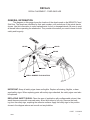
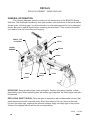
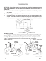
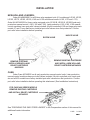
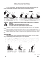
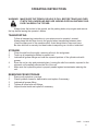
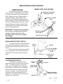
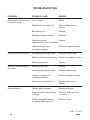
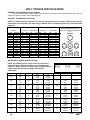
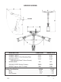
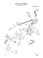
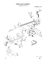
1
OPERATOR’S AND PARTS
MANUAL
FIXED & SWING
SKID HOE
SERIAL NUMBER: ___________________
MODEL NUMBER: ___________________
800-456-7100 I www.paladinlcg.com
Manual Number: OM731
Part Number: 75631
Rev. 3
503 Gay Street, Delhi, IA 52223, United States of America
11098
1-22-10-4
TABLE OF CONTENTS
PREFACE...........................................................................................................................................................3
SAFETY PRECAUTIONS
SAFETY STATEMENTS............................................................................................................................ 5
GENERAL SAFETY PRECAUTIONS.....................................................................................................5-7
EQUIPMENT SAFETY PRECAUTIONS................................................................................................... 8
DECALS
DECAL PLACEMENT . ........................................................................................................................9-10
DECALS.................................................................................................................................................. 11
PREOPERATION
General information...................................................................................................................... 12
PREPARING THE SKID STEER LOADER........................................................................................12-13
SECONDARY RELIEF VALVE INSTALLATION.................................................................................13-14
NOMENCLATURE................................................................................................................................... 14
INSTALLATION
attaching............................................................................................................................................15
skid hoe hydraulics....................................................................................................................... 15
detaching............................................................................................................................................15
SUPPLEMENTAL - RELIEF VALVE INSTALLATIONS.......................................................................15-16
operating instructions
general information...................................................................................................................... 17
basic digging technique..........................................................................................................17-18
backfilling.........................................................................................................................................18
transporting.................................................................................................................................... 19
PREPARING AND REMOVING FROM storage................................................................................ 19
maintenance AND SERVICE
general information...................................................................................................................... 20
before each use or after every 8 hours of operation................................................. 20
lubrication.........................................................................................................................................21
replacing bucket teeth............................................................................................................... 21
changing buckets........................................................................................................................... 21
cylinder seal replacement...................................................................................................22-23
troubleshooting............................................................................................................................24-25
specifications
BOLT TORQUE SPECIFICATIONS........................................................................................................ 26
skid hoe specifications................................................................................................................. 27
limited warranty.................................................................................................................................. 29
PARTS
FIXED SKID HOE ASSEMBLY...........................................................................................................30-31
SWING SKID HOE ASSEMBLY.........................................................................................................32-35
BUCKET CYLINDER ASSEMBLY......................................................................................................36-37
SWING CYLINDER ASSEMBLY........................................................................................................38-39
Hose Spring Clamp Assembly.................................................................................................40-41
OPTIONAL ELECTRICAL CONTROL BOX.......................................................................................42-43
11099
75631
5-28-09-2
1
THIS PAGE
IS INTENTIONALLY
BLANK
2
75631
PREFACE
GENERAL COMMENTS
Congratulations on the purchase of your new BRADCO product! This product was carefully designed and manufactured to give you many years of dependable service. Only minor
maintenance (such as cleaning and lubricating) is required to keep it in top working condition.
Be sure to observe all maintenance procedures and safety precautions in this manual and on
any safety decals located on the product and on any equipment on which the attachment is
mounted.
This manual has been designed to help you do a better, safer job. Read this manual
carefully and become familiar with its contents.
WARNING! Never let anyone operate this unit without reading the "Safety Precautions"
and "Operating Instructions" sections of this manual.
Always choose hard, level ground to park the vehicle on and set the brake
so the unit cannot roll.
Unless noted otherwise, right and left sides are determined from the operator’s control
position when facing the attachment.
NOTE: The illustrations and data used in this manual were current (according to the
information available to us) at the time of printing, however, we reserve the right to redesign and change the attachment as may be necessary without notification.
BEFORE OPERATION
The primary responsibility for safety with this equipment falls to the operator. Make
sure the equipment is operated only by trained individuals that have read and understand this
manual. If there is any portion of this manual or function you do not understand, contact your
local authorized dealer or the manufacturer.
SAFETY ALERT SYMBOL
This is the "Safety Alert Symbol" used by this industry. This symbol is used to
warn of possible injury. Be sure to read all warnings carefully. They are included
for your safety and for the safety of others working with you.
SERVICE
When servicing your product, remember to use only manufacturer replacement parts.
Substitute parts may not meet the standards required for safe, dependable operation.
To facilitate parts ordering, record the model and serial number of your unit in the space
provided on the cover of this manual. This information may be obtained from the identification
plate located on the product.
The parts department needs this information to ensure that you receive the correct parts
for your specific model.
10344
75631
8-20-05
3
THIS PAGE
IS INTENTIONALLY
BLANK
4
75631
SAFETY STATEMENTS
THIS SYMBOL BY ITSELF OR WITH A WARNING WORD THROUGHOUT THIS MANUAL IS USED TO CALL YOUR ATTENTION TO INSTRUCTIONS INVOLVING YOUR
PERSONAL SAFETY OR THE SAFETY OF OTHERS. FAILURE TO FOLLOW THESE
INSTRUCTIONS CAN RESULT IN INJURY OR DEATH.
DANGER
THIS SIGNAL WORD IS USED WHERE SERIOUS INJURY OR DEATH
WILL RESULT IF THE INSTRUCTIONS ARE NOT FOLLOWED PROPERLY.
WARNING
THIS SIGNAL WORD IS USED WHERE SERIOUS INJURY OR DEATH
COULD RESULT IF THE INSTRUCTIONS ARE NOT FOLLOWED PROPERLY.
CAUTION
THIS SIGNAL WORD IS USED WHERE MINOR INJURY COULD RESULT IF
THE INSTRUCTIONS ARE NOT FOLLOWED PROPERLY.
NOTICE
NOTICE INDICATES A PROPERTY DAMAGE MESSAGE.
GENERAL SAFETY PRECAUTIONS
WARNING! READ MANUAL PRIOR TO INSTALLATION
Improper installation, operation, or maintenance of this equipment could result in
serious injury or death. Operators and maintenance personnel should read this manual, as well as all manuals related to this equipment and the prime mover thoroughly
before beginning installation, operation, or maintenance. FOLLOW ALL SAFETY
INSTRUCTIONS IN THIS MANUAL AND THE PRIME MOVER’S MANUAL(S).
READ AND UNDERSTAND ALL SAFETY STATEMENTS
Read all safety decals and safety statements in all manuals prior to operating or
working on this equipment. Know and obey all OSHA regulations, local laws, and
other professional guidelines for your operation. Know and follow good work
practices when assembling, maintaining, repairing, mounting, removing, or operating
this equipment.
KNOW YOUR EQUIPMENT
Know your equipment’s capabilities, dimensions, and operations before operating.
Visually inspect your equipment before you start, and never operate equipment that
is not in proper working order with all safety devices intact. Check all hardware to
ensure it is tight. Make certain that all locking pins, latches, and connection devices
are properly installed and secured. Remove and replace any damaged, fatigued, or
excessively worn parts. Make certain all safety decals are in place and are legible.
Keep decals clean, and replace them if they become worn or hard to read.
10338
75631
8-16-05
5
GENERAL SAFETY PRECAUTIONS
WARNING! PROTECT AGAINST FLYING DEBRIS
Always wear proper safety glasses, goggles, or a face shield when driving pins in or
out, or when any operation causes dust, flying debris, or any other hazardous material.
WARNING! LOWER OR SUPPORT RAISED EQUIPMENT
Do not work under raised booms without supporting them. Do not use support material made of concrete blocks, logs, buckets, barrels, or any other material that could
suddenly collapse or shift positions. Make sure support material is solid, not decayed, warped, twisted, or tapered. Lower booms to ground level or on blocks. Lower
booms and attachments to the ground before leaving the cab or operator’s station.
WARNING! USE CARE WITH HYDRAULIC FLUID PRESSURE
Hydraulic fluid under pressure can penetrate the skin and cause serious injury or
death. Hydraulic leaks under pressure may not be visible. Before connecting or disconnecting hydraulic hoses, read your prime mover’s operator’s manual for detailed
instructions on connecting and disconnecting hydraulic hoses or fittings.
• Keep unprotected body parts, such as face, eyes, and arms as far away as
possible from a suspected leak. Flesh injected with hydraulic fluid may develop
gangrene or other permanent disabilities.
• If injured by injected fluid, see a doctor at once. If your doctor is not familiar with
this type of injury, ask him to research it immediately to determine proper treatment.
• Wear safety glasses, protective clothing, and use a piece of cardboard or wood
when searching for hydraulic leaks. DO NOT USE YOUR HANDS!
SEE ILLUSTRATION.
CARDBOARD
HYDRAULIC HOSE
OR FITTING
MAGNIFYING GLASS
10339
6
8-16-05
75631
GENERAL SAFETY PRECAUTIONS
WARNING! DO NOT MODIFY MACHINE OR ATTACHMENTS
Modifications may weaken the integrity of the attachment and may impair the function, safety, life, and performance of the attachment. When making repairs, use only
the manufacturer’s genuine parts, following authorized instructions. Other parts may
be substandard in fit and quality. Never modify any ROPS (Roll Over Protection
Structure) or FOPS (Falling Object Protective Structure) equipment or device. Any
modifications must be authorized in writing by the manufacturer.
WARNING! SAFELY MAINTAIN AND REPAIR EQUIPMENT
• Do not wear loose clothing or any accessories that can catch in moving parts. If
you have long hair, cover or secure it so that it does not become entangled in the
equipment.
• Work on a level surface in a well-lit area.
• Use properly grounded electrical outlets and tools.
• Use the correct tools for the job at hand. Make sure they are in good condition for
the task required.
• Wear the protective equipment specified by the tool manufacturer.
SAFELY OPERATE EQUIPMENT
Do not operate equipment until you are completely trained by a qualified operator
in how to use the controls, know its capabilities, dimensions, and all safety requirements. See your machine’s manual for these instructions.
• Keep all step plates, grab bars, pedals, and controls free of dirt, grease, debris,
and oil.
• Never allow anyone to be around the equipment when it is operating.
• Do not allow riders on the attachment or the prime mover.
• Do not operate the equipment from anywhere other than the correct operator’s
position.
• Never leave equipment unattended with the engine running, or with this attachment in a raised position.
• Do not alter or remove any safety feature from the prime mover or this attachment.
• Know your work site safety rules as well as traffic rules and flow. When in doubt
on any safety issue, contact your supervisor or safety coordinator for an explanation.
10340
75631
8-16-05
7
EQUIPMENT SAFETY PRECAUTIONS
WARNING! KNOW WHERE UTILITIES ARE
Observe overhead electrical and other utility lines. Be sure equipment will clear them.
When digging, call your local utilities for location of buried utility lines, gas, water, and
sewer, as well as any other hazard you may encounter.
WARNING! EXPOSURE TO RESPIRABLE CRYSTALLINE SILICA DUST
ALONG WITH OTHER HAZARDOUS DUSTS MAY CAUSE SERIOUS OR FATAL RESPIRATORY DISEASE.
It is recommended to use dust suppression, dust collection and if necessary personal
protective equipment during the operation of any attachment that may cause high
levels of dust.
OPERATING THE SKID HOE
• Block off work area from bystanders, livestock, etc. Allow plenty of room for skid hoe
swing.
• Operate only from the operator’s station.
• Use the skid hoe only for digging. Do not use the skid hoe to pull things, as a battering
ram, or attach ropes, chains etc., to the unit.
• Do not lift loads in excess of the capacity of the skid hoe or prime mover.
• When operating on slopes, dig with the skid hoe uphill, and avoid swinging the skid
hoe to the downhill side. Avoid steep hillside operation, which could cause the prime
mover to overturn.
• Reduce speed when driving over rough terrain, on a slope, or turning, to avoid overturning the prime mover.
• An operator must not use drugs or alcohol, which can change his or her alertness or
coordination. An operator taking prescription or over-the-counter drugs should seek
medical advice on whether or not he or she can safely operate equipment.
• Before exiting the prime mover, lower the skid hoe to the ground, turn off the prime
mover’s engine, remove the key and apply the brakes.
TRANSPORTING THE SKID HOE
• Travel only with the attachment in a safe transport position to prevent uncontrolled
movement. Drive slowly over rough ground and on slopes.
• When driving on public roads use safety lights, reflectors, Slow Moving Vehicle signs
etc., to prevent accidents. Check local government regulations that may affect you.
• Do not drive close to ditches, excavations, etc., cave-in could result.
• Do not smoke when refueling the prime mover. Allow room in the fuel tank for expansion. Wipe up any spilled fuel. Secure cap tightly when done.
MAINTAINING THE SKID HOE
• Before performing maintenance, lower the attachment to the ground, turn off the engine,
remove the key and apply the brakes.
• Never perform any work on the attachment unless you are authorized and qualified
to do so. Always read the operator service manuals before any repair is made. After
completing maintenance or repair, check for correct functioning of the skid hoe. If not
functioning properly, always tag “DO NOT OPERATE” until all problems are corrected.
• Worn, damaged, or illegible safety decals must be replaced. New safety decals can be
ordered from BRADCO.
• Never make hydraulic repairs while the system is under pressure, or cylinders under
load. Serious personal injury or death could result.
10341
2-29-08-2
• Never work under a raised attachment.
8
75631
DECALS
DECAL PLACEMENT - FIXED SKID HOE
GENERAL INFORMATION
The diagram on this page shows the location of the decals used on the BRADCO Fixed
Skid Hoe. The decals are identified by their part numbers, with reductions of the actual decals
shown. Use this information to order replacements for lost or damaged decals. Be sure to read
all decals before operating the attachment. They contain information you need to know for both
safety and longevity.
#40150
#41092
#40440
#4338
LOGO
#40151
SERIAL NUMBER TAG LOCATION
IMPORTANT: Keep all safety signs clean and legible. Replace all missing, illegible, or damaged safety signs. When replacing parts with safety signs attached, the safety signs must also
be replaced.
REPLACING SAFETY SIGNS: Clean the area of application with nonflammable solvent, then
wash the same area with soap and water. Allow the surface to fully dry. Remove the backing from the safety sign, exposing the adhesive surface. Apply the safety sign to the position
shown in the diagram above and smooth out any bubbles.
11087
75631
5-28-09-2
9
DECALS
DECAL PLACEMENT - SWING SKID HOE
GENERAL INFORMATION
The following diagrams show the location of the decals used on the BRADCO Swing
Skid Hoe. The decals are identified by their part numbers, with reductions of the actual decals
shown on the following page. Use this information to order replacements for lost or damaged
decals. Be sure to read all decals before operating the attachment. They contain information
you need to know for both safety and longevity.
#40150
SERIAL TAG
LOCATION
#4136
MODEL
NUMBER
#40149
#40440
#4084
#41092
#4338
#40151
LOGO
IMPORTANT: Keep all safety signs clean and legible. Replace all missing, illegible, or damaged safety signs. When replacing parts with safety signs attached, the safety signs must also
be replaced.
REPLACING SAFETY SIGNS: Clean the area of application with nonflammable solvent, then
wash the same area with soap and water. Allow the surface to fully dry. Remove the backing from the safety sign, exposing the adhesive surface. Apply the safety sign to the position
shown in the diagram above and smooth out any bubbles.
11439
10
5-27-09
75631
DECALS
made in usa
part #4338
MADE IN USA
part #40149
DANGER! PINCH POINT
part #40151
WARNING! HIGH PRESSURE FLUID
part #4084
GREASE 8 HOURS
part #40150
WARNING! READ MANUAL
part #40440
CALL BEFORE YOU DIG
part #41092
CAUTION DECAL
NOTE: CONTACT YOUR LOCAL DEALER TO
PURCHASE LOGO AND MODEL NUMBER
DECALS.
part #4136
SWING CHAIN ADJUSTMENT
11440
75631
5-27-09
11
PREOPERATION
GENERAL INFORMATION
The BRADCO Skid Hoe was designed to be easy to use and maintain.
WARNING! Never let anyone operate this equipment without first reading this manual,
as well as all manuals related to this equipment and the prime mover. Follow all safety and operating instructions.
Operate the skid hoe only when properly seated in the skid steer’s operating station. Any other method could result in serious personal injury or
death.
Check the prospective digging area for hidden utility lines before operating
the skid hoe. If in doubt of their location, contact the local utility companies. When operating the unit in an area where utility lines are expected to
be present, proceed with caution. If the bucket makes contact with anything
out of the ordinary, stop digging at once, and have the obstruction checked
by hand. If a utility line has been damaged, contact the affected utility company immediately.
PREPARING THE SKID STEER LOADER
CAUTION! THIS ATTACHMENT REQUIRES BASE-END BUCKET CIRCUIT PORT RELIEF
VALVE TO BE INSTALLED IN THE LOADER CONTROL VALVE. CONFIRM
PORT RELIEF VALVE INSTALLATION BEFORE OPERATING THIS ATTACHMENT.
If your unit does not have a factory installed relief in the base end of the loader control
valve bucket cylinder circuit, contact you local dealer and have one installed before installing
and operating the skid hoe. This cartridge is in addition to any existing rod-end relief cartridge
and protects the skid steer from hydraulic failure and/or loader bucket cylinder damage.
Bobcat: Units with BICS (Bobcat Interlock Control System) do not require additional relief. Units without BICS but with a plug and relief on the tilt spool require Bobcat part
#6599161 cartridge to replace the plug.
Case: Order Case #87445935 on all early production manual-control units. Later production
manual-control machines have port relief valve included. All pilot-controlled units, track
models and all 450 models have factory installed port relief valve since first production.
Confirm port relief valve installation before operating this attachment. (See Installation
Instructions)
Gehl: Models 7600, 7800 and 7810E install Gehl #138703 cartridge. Install into main control
valve opposite the existing cartridge on the bucket circuit spool.
John Deere: Models 4475, 5575, 6675, 7775 and 8875 require John Deere #MG86529091.
The following models require Bradco #LAF4495: Model 240 (up to SN#440000), 250 (up
to SN#450000), 260 (up to SN#460000) and 270 (up to SN#470000). All others along
with Model 280 (SN#480001 and up) require no additional relief.
11088
12
9-1-09-2
75631
PREOPERATION
Mustang: Models 2095 and 2105 install Gehl #138703 cartridge. Install into main control valve
opposite the existing cartridge on the bucket circuit spool.
New Holland: Order NH #86529091 for all Eaton valve equipped units (LX models and LS140,
LS150, LS160, LS170, LS180, LS190, L140 and L150 along with manual-control L160,
L170 and L175.) Order NH #87445939 for Husco valve equipped units (LS180.B,
LS185.B, LS190.B and early production manual-control L180, L185 and L190.) Later production L180, L185, L190 manual-control machines have port relief valves included. All
pilot-controlled L160 and larger and track models LT and C have had factory installed port
relief valves since first production. Confirm port relief valve installation before operating.
(See Installation Instructions)
Others: There is a secondary relief valve #LAF4264 available from your Bradco dealer for all
units that do not have a base-end port relief available. (See the following installation
instructions for installing this valve onto your skid steer loader.)
SECONDARY RELIEF VALVE INSTALLATION (PART #LAF4264)
The purpose of this valve is to relieve high pressure in the loaders bucket cylinder circuit
when the loader control valve does not have a port relief for this circuit. Read these instructions and your loader manual before attempting installation.
1.
Clean the prime mover before working on the hydraulic system.
2.
Remove any attachments from the skids steer loader and park on a level surface.
3.
Shut off the engine, set the parking brake and relieve any hydraulic pressure in the system before connecting or disconnecting hydraulic lines.
4.
Locate a convenient place to “tee” into the loader’s bucket circuit lines after they have
passed through any self-leveling devices or any other devices which may be present on
these lines. Refer to your loader’s service manual.
5.
Locate a convenient area to “tee” into a return-to-tank line.
6.
Once these areas have been located, find an area in close proximity for mounting the
relief valve. Although the valve can be mounted in any position, every effort should be
made to ensure accessibility to the valve, its cartridges, fittings and any lines that will
be added. Careful consideration should also be made as to the type and size of the fittings and hoses that will be required before dismantling any hydraulic circuitry. Keep any
added fittings, hoses, and the valve a safe distance from all moving parts of the machine.
Any .38” SAE o’ring fittings, JIC fittings and .38” hydraulic hoses are all adequate for the
amount of flow required. The valve’s ports accept #6 (.38”) SAE o’rings.
7.
Install the line from the base-end of the loader’s bucket cylinders into port “B” on the
valve. Install the line from the rod-end of the cylinder into port “R” on the valve and the
return to the tank line into port “T”. Make sure all fittings and hoses are tightened securely
and no hoses are stretched, bent, or kinked before mounting the valve.
8.
Using the valve as a template, mark and drill two .25” holes.
75631
11089
9-1-09-2
13
PREOPERATION
IMPORTANT: When drilling holes, be sure that you are not drilling into a reservoir or any
other sealed compartment. Also be careful not to damage any hydraulic lines, fittings or
components.
9.
Secure the valve to the loader using .25” hardware. Check all connections for proper fit
and tightness.
10.
Replace any guards, shields or covers that were removed.
11.
Replace any hydraulic fluid that may have been lost. See your loader’s manual for specifications. (Start loader, reposition the loader arms and bucket cylinders according to the
loader manufacturer’s recommendations for checking fluid levels. Add fluid as needed.)
BUCKET CYLINDER(S)
BASE END
FLOW OUT
ROD END
LOADER
CONTROL VALVE
FLOW IN
BOOM CYL’S BASE END
NOMENCLATURE
BOOM CYL’S ROD END
Throughout this manual, reference is made to various skid hoe components. Study the
following diagrams to acquaint yourself with the various names of these components. This
knowledge will be helpful when reading through this manual or when ordering service parts.
There is a complete parts breakdown for the skid hoes at the back of this manual.
SWING SKID HOE
FIXED SKID HOE
BUCKET
CYLINDER
STEP
14
STEP
DIPPER
LINK
BUCKET
LINK
SWING
CYLINDER
DIPPER
MOUNTING
FRAME
BUCKET
CYLINDER
DIPPER LINK
BUCKET
MOUNTING
FRAME
BUCKET
LINK
DIPPER
BUCKET
11090
5-27-09-2
75631
INSTALLATION
ATTACHING
Install the skid hoe by following your prime mover’s operator’s manual for installing an
attachment.
WARNING! To avoid serious personal injury, make sure the skid hoe is securely
latched to the attachment mechanism of your unit. Failure to do so could
result in separation of the attachment from the unit.
SKID HOE HYDRAULICS
When installing a skid hoe onto your unit, finish the installation by connecting the couplers on the skid hoe to the auxiliary hydraulic couplers on your prime mover. If installing a
swing hoe, also connect the wire assembly from the hydro-electric valve on the swing hoe to
the optional control box or to the skid steer’s auxiliary electrical outlet (if so equipped). Start
the engine and slowly cycle the cylinder(s) several times to purge system of air and check for
proper hydraulic connection, hose routing and hose length. Check for any hydraulic leaks and
correct if necessary.
DETACHING
On firm level ground, lower the skid hoe to the ground. Turn off the engine.
Move the control levers back and forth to relieve pressure in the line. Disconnect couplers. (If detaching a swing hoe, also disconnect the wire assembly going to either the electrical control box or the auxiliary electrical outlet on your prime mover.)
NOTE: Connect couplers together or install dust caps to prevent contaminants from
entering the hydraulic system.
Follow your prime mover’s operator’s manual for detaching (removing) an attachment.
NOTE: Frequent lubrication of grease fittings at the end of the cylinders and/or pivot
points with a multi-purpose grease will greatly increase the life of the product.
SUPPLEMENTAL
CAUTION! THIS ATTACHMENT REQUIRES BASE-END BUCKET CIRCUIT PORT RELIEF
VALVE TO BE INSTALLED IN THE LOADER CONTROL VALVE. CONFIRM
PORT RELIEF VALVE INSTALLATION BEFORE OPERATING THIS ATTACHMENT.
If your unit does not have a factory installed relief in the base-end of the loader control
valve bucket cylinder circuit, contact your local dealer and have one installed before installing
and operating the skid hoe. This cartridge is in addition to any existing rod-end relief cartridge
and protects the skid steer from hydraulic failure and/or loader bucket cylinder damage.
11091
75631
5-27-09-2
15
INSTALLATION
NEW HOLLAND LOADERS:
Order NH #86529091 for all Eaton valve equipped units (LX models and LS140, LS150,
LS160, LS170, LS180, LS190, L140 and L150 and manual-control L160, L170 and L175).
Order NH #87445939 for Husco valve equipped units (LS180.B, LS185.B, LS190.B and early
production manual-control L180, L185 and L190). Later production L180, L185, L190 manualcontrol machines have port relief valves included. All pilot-controlled L160 and larger plus track
models LT and C have had factory installed port relief valves since first production. Confirm
port relief valve installation before operating.
HUSCO VALVE
EATON VALVE
REMOVE PLUG AND
INSTALL NEW HOLLAND
RELIEF CARTRIDGE
#86529091
REMOVE EXISTING CARTRIDGE
AND INSTALL NEW HOLLAND
RELIEF CARTRIDGE #87445939
CASE:
Order Case #87445935 on all early production manual-control units. Later production
manual-control machines have port relief valves included. All pilot-controlled units, track models and all 450 models have factory installed port relief valves since first production. Confirm
port relief valve installation before operating this attachment. (See Installation Instructions)
FOR CASE 400 SERIES MODELS
REMOVE EXISTING CARTRIDGE
AND INSTALL RELIEF CARTRIDGE
#87445935
See “PREPARING THE SKID STEER LOADER” in the Preoperation section of this manual for
additional loader information.
11092
16
9-1-09-2
75631
OPERATING INSTRUCTIONS
GENERAL INFORMATION
When operating the skid hoe, smoothness of technique should be strived for at all times.
Smoothness will come with experience and practice at feathering the controls. Establish a flowing digging cycle to increase operator efficiency and save unnecessary wear on the machine.
Observe the following instructions to obtain the best results and to fully utilize the digging force of the skid hoe.
WARNING! Read and understand the Safety Precautions section of this manual before
beginning any skid hoe operation.
Operate the attachment only from the operator’s station. Any other method
could result in serious personal injury or death.
Check the prospective digging area for hidden utility lines before operating
the skid hoe. If in doubt of their location, contact the local utility companies. When operating the unit in an area where utilities are expected to be
present, throttle the skid hoe down and proceed with caution. If you feel the
bucket make contact with anything out of the ordinary, stop digging at once
and have the obstruction checked by hand. If a utility line has been damaged, contact the affected utility company immediately.
BEFORE YOU START DIGGING
Before any excavating is started, it is always a good idea to plan the job first. Various
things need to be considered and taken into account prior to the actual digging. The operator
should inspect the job site and take notice of any potential hazards in the area. He/she should
have a complete understanding of the tasks he/she is expected to perform. Figure out what will
be done with the spoil (excavated soil), Will it be used to backfill? What are the soil conditions?
Will you have to work around others? Etc.
BASIC DIGGING TECHNIQUE
When starting an excavation, make the first cut of each section shallow, being careful to
follow the exact layout of the excavation. The reason for the shallow cut is to minimize damage
to the sod and to facilitate replacement. These first cuts are also important because they will
act as guides for the remaining cuts. Thus getting the first few cuts as accurate as possible will
help in keeping all future cuts accurate.
When digging with the skid hoe, the loader arms should be partially raised with the
bucket out, away from the operator. Lower the dipper and start the digging process. The bucket
teeth should be at a 30° to 45° entry angle. With the bucket on the ground, simultaneously curl
the dipper toward the loader (using the loader arms) and roll the bucket until the bucket is full.
(If the bucket stalls (wheels slide) raise the loader arms slightly and continue to dig until the
bucket is full.) With the bucket full, raise the bucket out of the trench, and either rotate the skid
steer and dump the spoil in the desired location or if using a swing hoe, swing the bucket to the
side and dump the spoil in the desired location.
11093
75631
9-1-09-3
17
OPERATING INSTRUCTIONS
To dig a shallow trench, reach the desired depth by following the basic digging techniques and then slowly back up the loader, keeping the bucket height constant.
BASIC DIGGING
DIGGING A SHALLOW TRENCH
WARNING! To prevent serious personal injury or death from cave-in or prime mover
overturn;
Always back away from trenches before turning.
Do not dig close to the loader wheels or under the loader.
The depth of the hole or trench will be controlled by dipper extension and loader arm
height.
Use caution when working close to fences, ditches or on uneven ground and slopes. Always dump a loaded bucket on the uphill side of the hoe to minimize the possibility of turnover.
Use the flat sides of the bucket to scrape off any high spots on the sides of the excavation.
BACKFILLING
There are several options available for backfilling a hole or trench. The spoil location
and job will determine which procedure is best for your application.
• Use the side of the bucket and pivot the loader toward the trench or hole or use the skid
hoe swing (if equipped) to PUSH the spoil into the trench or hole.
• Use the bucket to reach beyond the trench and travel in reverse to PULL the spoil into the
trench or hole.
• Use the back of the bucket and travel forward to PUSH the spoil into the trench or hole.
USE SIDE OF BUCKET TO
PUSH SPOIL INTO TRENCH
USE BUCKET TO PULL
SPOIL INTO TRENCH
USE BUCKET TO PUSH
SPOIL INTO TRENCH
11094
18
5-27-09-2
75631
OPERATING INSTRUCTIONS
WARNING! MAKE SURE THE TRENCH OR HOLE IS FULL BEFORE TRAVELING OVER
IT WITH THE LOADER AND SKID HOE. MOVING OVER AN UNSTABLE SURFACE CAN RESULT IN TIPOVER.
Always lower the bucket to the ground, set the parking brake, stop engine and remove
the key before leaving the operator’s station.
TRANSPORTING
Follow all transporting instructions in your prime mover’s operator’s manual.
Always keep the skid hoe close to the ground when transporting between sites.
Keep the heavy end of the machine uphill. Avoid abrupt starts, stops and turns.
Be sure skid hoe is securely tied down when transporting on a truck or trailer bed.
STORAGE
1.
2.
3.
4.
5.
Clean the skid hoe thoroughly, removing all mud, dirt and grease.
Touch up all unpainted surfaces to prevent rust.
Lubricate all grease fittings and coat the exposed portions of the cylinder rods with
grease.
Store the unit a a dry and protected place. Leaving the skid hoe outside, exposed to the
elements, will materially shorten the life of the unit.
Make sure the hydraulic system is properly sealed against contaminates entering the
unit.
REMOVING FROM STORAGE
1.
2.
3.
4.
5.
Remove all protective coverings.
Check hydraulic hoses for deterioration and replace if necessary.
Lubricate all grease fitting.
Tighten all loose bolts and fittings.
Inspect bucket teeth and replace if necessary.
10352
75631
9-1-09-2
19
MAINTENANCE AND SERVICE
GENERAL INFORMATION
Regular maintenance is the key to long equipment life and safe operation. Maintenance
requirements have been reduced to an absolute minimum. However it is very important that
these maintenance procedures be performed as described in this section.
WARNING! Read the Safety Precautions section of this manual before performing any
maintenance procedure.
Follow any Safety Shutdown procedures outlined in the loader operator’s
manual before performing maintenance.
BEFORE EACH USE OR AFTER EVERY 8 HOURS OF OPERATION
•
•
•
•
•
•
Lubricate all grease fittings.
Check all bolts are properly tightened and all pins are securely in place.
Check hydraulic fittings for proper tightness and leaks.
Check hydraulic hoses for leaks or deterioration.
Check all safety signs are clean and legible.
Replace any damaged or excessively worn parts.
WARNING! Escaping hydraulic fluid under pressure can have sufficient force to penetrate the skin causing serious personal injury. Fluid escaping from a very
small hole can be almost invisible. Use a piece of cardboard or wood rather
than your hands to search for suspected leaks.
Keep unprotected body parts, such as face, eyes, and arms as far away
as possible from a suspected leak. Flesh injected with hydraulic fluid may
develop gangrene or other permanent disabilities.
If injured by injected fluid see a doctor at once. If your doctor is not familiar
with this type of injury, ask him/her to research it immediately to determine
proper treatment.
CARDBOARD
HYDRAULIC HOSE
OR FITTING
MAGNIFYING
GLASS
10353
20
8-31-05
75631
MAINTENANCE AND SERVICE
LUBRICATION
(SWING SKID HOE SHOWN)
Economical and efficient operation
of any machine is dependent upon regular
and proper lubrication of all moving parts
with a quality lubricant. Neglect leads to
reduced efficiency, heavy draft, wear,
breakdown and needless replacement of
parts. All parts provided with grease fittings
should be lubricated every 8 hours. If any
grease fittings are missing, replace them
immediately. Clean all fittings thoroughly
before using grease gun.
IMPORTANT: Avoid excessive greasing.
Dirt collects on exposed grease and
greatly increases the wear. After
greasing, wipe off excessive grease
from fittings.
SWING PIVOT PIN ENDS
(SWING HOE ONLY)
BUCKET CYLINDER
ENDS
BUCKET
LINK
DIPPER LINK
PIVOT PINS
BUCKET PIVOT PINS
REPLACING BUCKET TEETH
The bucket teeth are self-sharpening
and require little attention, however, they
can be replaced when they become worn or
broken.
Remove the two capscrews and lock
nuts securing the tooth to the bucket and
replace with new bucket teeth and hardware.
CHANGING BUCKETS
The bucket is connected to the
dipper and bucket link with snap ring style
pins. To change buckets, remove the
snap rings and washers from one side of
the pivot pins, slide the pins out and then
remove the old bucket. Position the new
bucket in its place. Install the pivot pins
and secure with snap rings and thrust
washers. Lubricate both pivot pin grease
fittings before operating.
TOOTH
#102831
BUCKET
.50” UNC DEFORMED
OVAL LOCK NUT
(#1841)
.50” UNC X 1.75”
CAPSCREW
(#1091)
BUCKET
LINK
DIPPER
SNAP RINGS
AND WASHERS
PIVOT PINS WITH
GREASE FITTINGS
BUCKET
11095
75631
5-27-09-2
21
MAINTENANCE AND SERVICE
CYLINDER SEAL REPLACEMENT
The following information is provided to assist you in the event you should need to repair or rebuild a hydraulic cylinder. When working on hydraulic cylinders, make sure that the work area and tools are clean and free
of dirt to prevent contamination of the hydraulic system and damage to the hydraulic cylinders. Always protect the
active part of the cylinder rod (the chrome section). Nicks or scratches on the surface of the rod could result in
cylinder failure. Clean all parts thoroughly with a cleaning solvent before reassembly.
DISASSEMBLY PROCEDURE
IMPORTANT: Do not contact the active surface of the cylinder rod with the vise. Damage to the rod could
result.
RETAINING RING TYPE GLAND
1. Mount the cylinder tube securely in a vise. NOTICE: Do not clamp too tight and distort the tube.
2. Rotate the gland with a spanner wrench (available from your dealer), until the gland retaining ring appears in
the milled slot.
Pry up the end of the gland retaining ring with a pointed tool. Rotate the gland with a spanner wrench while removing the retaining ring. NOTE: The gland and piston seal(s) can be pulled out and cut as they appear in
the milled slot during disassembly. After cutting, pull them on out through the milled slot.
3.
Pull the cylinder rod from the cylinder tube.
4.
Inspect the piston and the bore of the cylinder tube for deep scratches or galling. If damaged, the piston
and cylinder tube must be replaced.
5.
Remove the hex nut, piston, flat washer or spacer tube (if so equipped), and gland from the cylinder rod. If
the cylinder rod is rusty, scratched, or bent, it must be replaced.
6.
Remove and discard all old seals.
ASSEMBLY PROCEDURE
IMPORTANT: Replace all seals even if they do not appear to be damaged. Failure to replace all seals may
result in premature cylinder failure.
1.
Install the cylinder rod seal in the gland first. Be carefull not to damage the seal in the process as it is somewhat difficult to install. A special installation tool is available to help with installing the seal. Simply fit the end of the
tool over the seal so that the large prong of the tool is on the outside of the seal, and the two smaller prongs on the
inside. The lip of the seal should be facing towards the tool. Rotate the handles on the tool around to wrap the seal
around the end of the tool.
10530
22
3-8-06
75631
MAINTENANCE AND SERVICE
Now insert the seal into the gland from the inner end. Position the seal in its
groove, and release and remove the tool. Press the seal into its seat the rest of
the way by hand.
NOTE: Threaded gland is shown in diagram for reference only.
2.
Install the new piston ring, rod wiper, O-rings, and backup washers, if
applicable, on the piston. Be careful not to damage the seals. Caution must be
used when installing the piston ring. The ring must be stretched carefully over
the piston with a smooth, round, pointed tool.
3.
Slide the gland onto the cylinder rod being careful not to damage the rod
wiper. Then install the spacer, or flat washer (if so equipped), small O-ring, piston,
and hex nut onto the end of the cylinder rod.
4.
Secure the cylinder rod (mounting end) in a vise, with a support at its center. Torque the nut to the value shown on the chart for the thread diameter of the
cylinder rod.
Thread Diameter
7/8"
*1"
1-1/8"
1-1/4"
1-3/8"
POUNDS - FEET
150-200
230-325
350-480
490-670
670-900
* 1" Thread Diameter WITH 1.25" Rod Diameter
Min. 230 ft. lbs.
Max. 250 ft. lbs.
O - RING
BACKUP WASHER
IMPORTANT: Do not contact the active surface of the cylinder rod with the vise. Damage to the rod could
result.
IMPORTANT: Ensure that the piston ring fits squarely into the cylinder tube and piston groove, otherwise
the ring may be damaged and a leak will occur.
5.
Apply a lubricant (such as Lubriplate #105) to the piston and teflon ring. Insert the cylinder rod assembly
into the cylinder tube.
6.
Rotate the gland with a spanner wrench until the hole (drilled into the retaining slot of the gland) appears in
the milled slot of the cylinder tube. Insert the hooked end of the gland retaining rod into the hole.
Rotate the gland until the gland retaining rod forms a ring between the gland and the cylinder tube. When complete, the bent end of the gland retainer ring should be hidden (not turned so it is exposed in the slot) to prevent it
from popping out.
WARNING!
Cylinders serviced in the field are to be tested for leakage prior to the attachment being
placed in work. Failure to test rebuilt cylinders could result in damage to the cylinder and/or
the attachment, causing severe personal injury or even death.
10531
75631
3-8-06
23
TROUBLESHOOTING
PROBLEM
POSSIBLE CAUSE
REMEDY
Bucket fails to curl or swing Low oil supply
hoe fails to swing
Obstruction in hydraulic line
Add oil
Bent cylinder rod
Replace
Damaged hydraulic cylinder
Replace
Hydraulic couplers Replace
malfunctioning or non-compatible.
Bucket fails to maintain curl
Hydraulic couplers not completely engaged
Check and tighten couplers
Oil leaking past cylinder seals
Replace cylinder seals
Broken or leaking hydraulic lines Replace and check for leaks
Malfunctioning valve
Replace
Bucket or swing operating too slowly
Malfunctioning valve
Replace
Oil leaking past cylinder seals
Replace cylinder seals
Hydraulic couplers not completely engaged
Check and tighten couplers
Remove obstruction or
replace
Obstruction in hydraulic line
Remove obstruction or
replace
External leaking
Cylinder seals damaged
Replace and repair
Broken or loose hydraulic lines
or fittings
Check for leaks and repair
or replace
O’Rings damaged betweem
the valves (swing hoe only)
Replace O’rings.
11096
24
5-27-09-2
75631
TROUBLESHOOTING
PROBLEM
POSSIBLE CAUSE
REMEDY
Swing hoe functions in
No electrical power to solenoid
one circuit only
valve
Check for proper connection
in control box and power
from loader
Swing hoe functions in Valve malfunctioning
one circuit only WITH power
to the valve
Replace valve
Skid hoe not functioning
Incorrect hose routing
according to operation decal
Switch power and return
hoses at valve
11443
75631
5-27-09
25
BOLT TORQUE SPECIFICATIONS
GENERAL TORQUE SPECIFICATION TABLES
Use the following charts when determining bolt torque specifications when special torques are not given.
Always use grade 5 or better when replacing bolts.
SAE BOLT TORQUE SPECIFICATIONS
NOTE: The following torque values are for use with extreme pressure lubricants, plating or hard washer
applications Increase torque 15% when using hardware that is unplated and either dry or lubricated with
engine oil.
SAE GRADE 5 TORQUE
Bolt Size
Pounds Feet
Newton-Meters
SAE GRADE 8 TORQUE
Pounds Feet
UNC
Newton-Meters
Inches
Millimeters
UNC
UNF
UNC
UNF
UNF
UNC
UNF
1/4
5/16
6.35
7.94
8
14
9
17
11
19
12
23
10
20
13
25
14
27
18
34
62
3/8
9.53
30
36
41
49
38
46
52
7/16
11.11
46
54
62
73
60
71
81
96
1/2
12.70
68
82
92
111
94
112
127
152
9/16
14.29
94
112
127
136
163
184
221
5/8
15.88
128
153
174
152
207
187
224
254
304
3/4
19.05
230
275
312
373
323
395
438
536
7/8
22.23
340
408
461
553
510
612
691
830
1
25.40
493
592
668
803
765
918
1037
1245
1-1/8
25.58
680
748
922
1014
1088
1224
1475
1660
1-1/4
31.75
952
1054
1291
1429
1547
1700
2097
2305
1-3/8
34.93
1241
1428
1683
1936
2023
2312
2743
3135
1-1/2
38.10
1649
1870
2236
2535
2686
3026
3642
4103
Bolt head identification marks as per
grade. NOTE: Manufacturing Marks Will
Vary
METRIC BOLT TORQUE SPECIFICATIONS
Bolt head identification marks as per grade.
NOTE: The following torque values are for use with metric
hardware that is unplated and either dry or lubricated with
engine oil. Reduce torque 15% when using hardware that has
extreme pressure lubricants, plating or hard washer
applications.
Size of Bolt
Grade No.
Pitch (mm)
Pounds Feet
Newton-Meters
Pitch (mm)
Pounds Feet
Newton-Meters
M6
5.6
8.8
10.9
1.0
3.6-5.8
5.8-.4
7.2-10
4.9-7.9
7.9-12.7
9.8-13.6
-
-
-
M8
5.6
8.8
10.9
1.25
7.2-14
17-22
20-26
9.8-19
23-29.8
27.1-35.2
1.0
12-17
19-27
22-31
16.3-23
25.7-36.6
29.8-42
M10
5.6
8.8
10.9
1.5
20-25
34-40
38-46
27.1-33.9
46.1-54.2
51.5-62.3
1.25
20-29
35-47
40-52
27.1-39.3
47.4-63.7
54.2-70.5
M12
5.6
8.8
10.9
1.75
28-34
51-59
57-66
37.9-46.1
69.1-79.9
77.2-89.4
1.25
31-41
56-68
62-75
42-55.6
75.9-92.1
84-101.6
M14
5.6
8.8
10.9
2.0
49-56
81-93
96-109
66.4-75.9
109.8-126
130.1-147.7
1.5
52-64
90-106
107-124
70.5-86.7
122-143.6
145-168
M16
5.6
8.8
10.9
2.0
67-77
116-130
129-145
90.8-104.3
157.2-176.2
174.8-196.5
1.5
69-83
120-138
140-158
93.5-112.5
162.6-187
189.7-214.1
M18
5.6
8.8
10.9
2.0
88-100
150-168
175-194
119.2-136
203.3-227.6
237.1-262.9
1.5
100-117
177-199
202-231
136-158.5
239.8-269.6
273.7-313
M20
5.6
8.8
10.9
2.5
108-130
186-205
213-249
146.3-176.2
252-277.8
288.6-337.4
1.5
132-150
206-242
246-289
178.9-203.3
279.1-327.9
333.3-391.6
26
10360
3-20-08-3
75631
SPECIFICATIONS
b
a
2”
ground
b
c
a
72” WIDE SKID STEER
D
DESCRIPTION
FIXED HOE
SWING HOE
A.
B.
C. D,
OVERALL WIDTH
OVERALL REACH (From Mounting Plate)
DIGGING DEPTH
(With Mounting Plate 2” Above Ground.)
SWING ANGLE
47.50”
75.00”
73.00”
47.50”
78.00”
76.00”
NA
140°
DIGGING FORCE (Bucket Cylinder)
WEIGHT (Approx. with 12” bucket)
3895#
395#
3800#
535#
Cylinder Specifications
105306
112126
Bore.................................................................................... 2.25”............................2.00”
Stroke................................................................................. 18.23”..........................7.73”
Rod Diameter..................................................................... 1.25”............................1.12”
11097
75631
5-28-09-2
27
THIS PAGE
IS INTENTIONALLY
BLANK
28
75631
Limited Warranty
Except for the Excluded Products as described below, all new products are warranted to be free from defects
in material and/or workmanship during the Warranty Period, in accordance with and subject to the terms and
conditions of this Limited Warranty.
1.
Excluded Products. The following products are excluded from this Limited Warranty:
(a) Any cable, part that engages with the ground (i.e. sprockets), digging chain, bearing, teeth, tamping
and/or demolition head, blade cutting edge, pilot bit, auger teeth and broom brush that either constitutes or is part
of a product.
(b) Any product, merchandise or component that, in the opinion of Paladin Light Construction1, has been
(i) misused; (ii) modified in any unauthorized manner; (iii) altered; (iv) damaged; (v) involved in an accident; or (vi)
repaired using parts not obtained through Paladin Light Construction.
2.
Warranty Period. The Limited Warranty is provided only to those defects that occur during the Warranty
Period, which is the period that begins on the first to occur of: (i) the date of initial purchase by an end-user, (ii) the
date the product is first leased or rented, or (iii) the date that is six (6) months after the date of shipment by Paladin
Light Construction as evidenced by the invoiced shipment date (the “Commencement Date”) and ends on the date
that is twenty-four (24) months after the Commencement Date.
3.
Terms and Conditions of Limited Warranty. The following terms and conditions apply to the Limited Warranty
hereby provided:
(a)
the product.
Option to Repair or Replace. Paladin Light Construction shall have the option to repair or replace
(b)
Timely Repair and Notice. In order to obtain the Limited Warranty, (i) the product must be repaired
within thirty (30) days from the date of failure, and (ii) a claim under the warranty must be submitted to Paladin Light
Construction in writing within thirty (30) days from the date of repair.
(c)
Return of Defective Part or Product. If requested by Paladin Light Construction, the alleged
defective part or product shall be shipped to Paladin Light Construction at its manufacturing facility or other location
specified by Paladin Light Construction, with freight PRE-PAID by the claimant, to allow Paladin Light Construction
to inspect the part or product.
Claims that fail to comply with any of the above terms and conditions shall be denied.
LIMITATIONS AND EXCLUSIONS.
THIS LIMITED WARRANTY IS IN LIEU OF ALL OTHER WARRANTIES, EXPRESS OR IMPLIED, INCLUDING
WITHOUT LIMITATION THE WARRANTIES OF MERCHANTABILITY, FITNESS FOR A PARTICULAR PURPOSE
AND ANY WARRANTY BASED ON A COURSE OF DEALING OR USAGE OF TRADE.
IN NO EVENT SHALL PALADIN LIGHT CONSTRUCTION BE LIABLE FOR CONSEQUENTIAL OR SPECIAL
DAMAGES.
IN NO EVENT SHALL PALADIN LIGHT CONSTRUCTION BE LIABLE FOR ANY LOSS OR CLAIM IN AN
AMOUNT IN EXCESS OF THE PURCHASE PRICE, OR, AT THE OPTION OF PALADIN LIGHT CONSTRUCTION,
THE REPAIR OR REPLACEMENT, OF THE PARTICULAR PRODUCT ON WHICH ANY CLAIM OF LOSS OR
DAMAGE IS BASED. THIS LIMITATION OF LIABILITY APPLIES IRRESPECTIVE OF WHETHER THE CLAIM
IS BASED ON BREACH OF CONTRACT, BREACH OF WARRANTY, NEGLIGENCE OR OTHER CAUSE AND
WHETHER THE ALLEGED DEFECT IS DISCOVERABLE OR LATENT.
Attachment Technologies Inc., a subsidiary of Paladin Brands Holding, Inc. (PBHI) is referred to herein as Paladin Light
Construction.
February 10, 2010
1
75631
29
FIXED SKID HOE ASSEMBLY
ASSEMBLY #111637
10
9
8
9
8
11
12
15
6
14
13
15
5
7
7
8
9
16
19
17
4
9
3
8
2
1
18
19
11085
30
5-27-09-2
75631
FIXED SKID HOE ASSEMBLY
ASSEMBLY #111637
ITEM
REQ’D
PART NO.
DESCRIPTION
1
2
3
4
5
1
1
1
1
1
111632
1502
1022
103178
14176
Backhoe Frame
.31” Lock Washer
.31” UNC X 1.00” Hex Capscrew
Hose Clamp Assembly
Male Coupler .50” Body 8FBo
6
7
8
9
10
1
2
6
6
1
14175
38033
1650
6623
105370
Female Coupler .50” Body 8FBo
Hose .38” x 87” 6FJX-8MBo
Snap Ring
Thrust Washer
Cylinder Pin
11
1
12
2
13
2
14
2
15
2
105306
45478
1536
1052
105373
105391
Cylinder Assembly
Replacement Seal Kit
.38” UNC Nylock Hex Nut
.38” UNC X 3.25” Hex Capscrew
Cylinder Pin
Dipper Link
16
1
3
17
2
18
Option
105390
6616
105375
81710
81712
81716
81718
81724
Bucket Link
Grease Fittings
Bucket Pin
10” Bucket
12” Bucket
16” Bucket
18” Bucket
24” Bucket
6616
Grease Fitting
19
9
11086
75631
9-11-09-3
31
SWING HOE ASSEMBLY
ASSEMBLY #112140
DIAGRAM 1 OF 2
1
2
3
39
41
4
12
16
18
13
15
10
14
17
19
15
15
20
28
21
9
5
6
7
8
22
24
21
33
30
34
30
25
29
27
21
32
23
21
31
37
15
35
15
11
26
27
40
34
33
36
38
32
11435
5-27-09
75631
SWING HOE ASSEMBLY
ASSEMBLY #112140
LIST 1 OF 2
REQ’D
PART NO.
1
2
3
4
1
1
2
4
8
4
14175
14176
38033
10227
1524
1934
5
6
7
8
9
10
2
1
1
-
1
1
2
3362
Straight Connector 10MBo-6MJ
17006
Diverter Valve
112137
Crossover Relief Valve
45839
Replacement O’Ring (Between Valves)
3457
Straight Connector 6MBo-6MJ
30369
Straight Connector 6MBo-6MJ with .046 Orifice
38614
Hose .25” X 15” 6FJX-6FJX 90°
11
12
13
14
2
2
2
2
1
10212
1501
38615
30143
112130
.25” X 3.00” Socket Head Capscrew
.25” Lock Washer
Hose .25” X 18.50” 6FJX-6FJX 90°
90° Elbow 10MBo-6MJ
Swing Hoe Frame
15
16
17
18
7
1
2
2
2
1
6616
105370
6623
1650
85772
105306
Grease Fitting
Pivot Pin
Thrust Washer
Snap Ring
Bushing (Included in Cylinder Assembly)
Cylinder Assembly
19
20
21
1
2
2
4
4
6615
1649
10001
54418
1611
Self Aligning Bushing (Included in Cylinder Assembly)
.75” Hard Flat Washer
.75” UNF Deformed Lock Nut
Clevis Pin
Cotter Pin
22
23
24
25
26
2
1
2
1
2
2
38616
112126
3282
62942
1043
1503
Hose .25” X 22” 6FJX-6FJX Wrap
Swing Cylinder Assembly
90° Bulkhead Fitting 6MJ-6MJ (Includes Nut)
Mounting Plate
.38” UNC X 1.00” Hex Capscrew
.38” Lock Washer
ITEM
DESCRIPTION
Female Coupler 8FBo .50” Body
Male Coupler
8FBo .50” Body
Hose Assembly .38” X 87” 6FJX-8MBo-HS
.31” X 4.75” Socket Head Capscrew
.31” Flat Washer
.31” UNC Deformed Lock Nut
11436
75631
5-27-09
33
SWING HOE ASSEMBLY
ASSEMBLY #112140
DIAGRAM 2 OF 2
1
2
3
39
41
4
12
16
18
13
15
10
14
17
15
19
20
28
21
11
9
5
6
7
8
22
15
24
21
29
27
33
30
34
30
25
21
32
21
31
37
15
27
23
26
40
35
15
34
33
36
38
11437
34
5-27-09
75631
SWING HOE ASSEMBLY
ASSEMBLY #112140
REQ’D
PART NO.
27
28
2
2
1
1
1
61165
1534
1042
1514
81807
Bolt
.75” UNC Nylock Nut
.38” UNC X .75” Hex Capscrew
.38” Flat Washer
Spacer Tube
29
30
31
1
6
1
1
1
112135
81610
64724
83976
1650
Pivot Pin
Replacement Bushing (Included with Boom)
Thrust Washer
Thrust Washer
Snap Ring
32
33
34
1
4
4
4
2
112120
6616
64724
1650
105391
Boom
Grease Fitting
Thrust Washer
Snap Ring
Dipper Link
35
36
37
38
2
2
2
1
2
1052
1536
105373
105390
105375
.38” UNC X 3.25” Hex Capscrew
.38” UNC Nylock Nut
Pivot Pin
Bucket Link
Pivot Pin
39
40
41
1
2
1
1
103178
88503
1022
1502
Spring Clamp Assembly
Swing Chain (13 Pitch)
.31” UNC X 1.00” Hex Capscrew
.31” Lock Washer
ITEM
LIST 2 OF 2
DESCRIPTION
11438
75631
5-27-09
35
BUCKET CYLINDER ASSEMBLY
ASSEMBLY #105306
4
2
5
6
7
3
1
16
15
14
13
9
10
11
12
8
10697
36
8-23-06
75631
BUCKET CYLINDER ASSEMBLY
ASSEMBLY #105306
ITEM
REQ’D
PART NO.
DESCRIPTION
1
2
3
4
5
1
1
1
1
1
105309
1483
86509
4641*
5421
Cylinder Tube
Hex Nut (Torque to 230-325 ft. lbs.)
Piston
O’Ring
Washer
6
7
8
9
10
1
1
1
1
1
45443*
45701*
45699*
45700*
86508
O’Ring
Piston Ring
O’Ring
Back-Up Washer
Gland
11
12
13
14
15
1
1
1
1
2
45219*
7165*
4974*
105307
85772
Poly-Pak Seal
Gland Retainer Rod
Rod Wiper
Cylinder Rod
Bushing
16
1
6615
Self-Aligning Bearing
NOTE: Seal Kit #45478 includes all parts marked with an asterisk(*). Parts are not sold
separately.
10698
75631
8-23-06
37
SWING CYLINDER ASSEMBLY
ASSEMBLY #112126
1
5
6
7
8
9
2
10
11
3
12
13
1
4
11441
38
5-27-09
75631
SWING CYLINDER ASSEMBLY
ASSEMBLY #112126
ITEM
REQ’D
PART NO.
DESCRIPTION
1
2
3
4
5
2
1
2
1
2
64891
88475
112128
112127
4981*
Gland
Cylinder Tube
Cushion Ring
Cylinder Rod
Rod Wiper
6
7
8
9
10
2
2
2
2
2
7164*
45262*
4634*
4633*
1998*
Gland Retainer Ring
Poly Pak Seal
Back-Up Washer
O'Ring
Retaining Ring
11
12
13
2
1
1
45760
4637*
4636*
Wear Ring
O-Ring
Piston Ring
NOTE: Seal Kit #45765 includes all parts marked with an asterisk (*). Parts are not sold
separately.
11442
75631
5-27-09
39
SPRING CLAMP ASSEMBLY
ASSEMBLY #103178
1
2
3
2
4
5
6
mounting hardware
determined by attachment
4
11100
40
3-6-08
75631
SPRING CLAMP ASSEMBLY
ASSEMBLY #103178
REQ’D
PART NO.
1
2
3
4
5
1
2
2
2
1
1030
103184
103181
105840
1753
6
1
RHW8618
ITEM
DESCRIPTION
.31” UNC X 3.00” Hex Capscrew
Top Plate
Hose Clamp (.75” ID Hose)
Fender Washer
.31” UNC Nylock Nut
Mounting Spring
11101
75631
3-6-08
41
OPTIONAL ELECTRICAL CONTROL BOX
ELECTRICAL CONTROL BOX ASSEMBLY #15756
1
2
3
30 AMP FUSE IN
FUSE HOLDER
TO ATTACHMENT
CONNECT TO
SKID-STEER
NEGATIVE
POSITIVE
9904
42
5-28-09-2
75631
OPTIONAL ELECTRICAL CONTROL BOX
ELECTRICAL CONTROL BOX ASSEMBLY #15756
ITEM
REQ’D
PART NO.
1
1
17709
2
3
DANGER!
1
1
17716
17173
DESCRIPTION
Control Box Assembly
(Includes one single pole, double throw,
normally open, momentary closed,
spring return toggle switch.)
Wire Assembly (To Attachment)
Wire Assembly (To Skid-Steer Power Supply)
ELECTROCUTION HAZARD
Provide electrical power to the control box by following your skid
steer manufacturer's recommended procedures.
The electrical circuit must be fused to prevent machine damage and
serious personal injury or death.
9905
75631
5-28-09-2
43