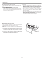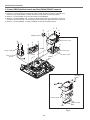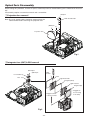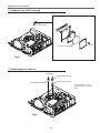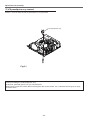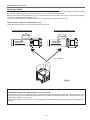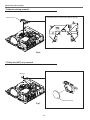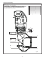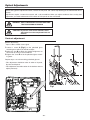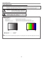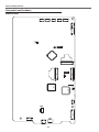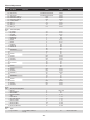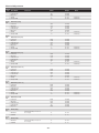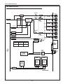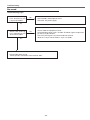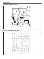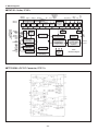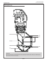
1
ORDER NO. VED1203417CE D10 LCD Projector Model No. PT-TW230 PT-TW230U PT-TW230E PT-TW230EA PT-TW231RU PT-TW231RE PT-TW231REA PT-TW231R *M odel PT-TW231R has an interactive module on the cabinet front. The illustrations in this manual are used for the model PT-TW230. © Panasonic Corporation 2012. Unauthorized copying and distribution is a violation of law. Contents Contents......................................................................... 2 Safety Instructions.......................................................... 3 Safety precautions....................................................... 4 Specifications................................................................. 5 Circuit Protections.......................................................... 7 Thermal fuse(SW902)................................................. 7 Fuse(F601).................................................................. 7 Lamp cover switch(SW901)......................................... 7 Warning temperature and power failure protection...... 8 Maintenance................................................................... 9 Maintenance................................................................ 9 Replacing the unit........................................................ 9 Replacing the lamp unit............................................. 12 How to check lamp runtime....................................... 13 Cleaning.................................................................... 14 Cleaning the projection lens...................................... 14 Cleaning the projector cabinet................................... 14 Security Function Notice.............................................. 15 Resetting procedure.................................................. 15 Standby Mode Notice................................................... 16 Mechanical Disassembly.............................................. 17 Optical Parts Disassembly............................................ 24 Servicing Notice........................................................... 30 Note on main board replacement.............................. 30 Adjustments.................................................................. 31 Adjustments after parts replacement......................... 31 Optical Adjustments...................................................... 32 Contrast adjustment.................................................. 32 Condenser lens (OUT) adjustment............................ 33 Relay lens (OUT) adjustment................................... 34 Electrical Adjustments.................................................. 35 Service adjustment menu operation.......................... 35 Circuit adjustments.................................................... 36 Test points and locations........................................... 40 Service adjustment data ........................................... 41 Chassis Block Diagrams............................................... 58 Chassis overview....................................................... 58 System control........................................................... 59 Power supply & protection circuit............................... 60 Fan control circuit...................................................... 61 Troubleshooting............................................................ 62 Indicators and projector condition.............................. 62 No power................................................................... 63 No picture.................................................................. 64 No sound................................................................... 65 Control Port Functions.................................................. 66 Scaler I/O port functions (PW190)............................. 66 IC Block Diagrams........................................................ 67 Exploded Views & Parts List................................... SPL-1 Exploded Views...................................................... SPL-2 Mechanical Parts List........................................... SPL-10 Electrical Parts List............................................... SPL-12 Schematic Diagram & Circuit Boards Diagram........ DIA-1 Pin description of diode, transistor and IC............ DIA-2 Schematic Diagrams............................................... DIA-3 Circuit Boards Diagram........................................... DIA-9 -2- Safety Instructions The service technician is required to read and follow the “Safety Precautions” and “Important Safety Notice” in this service manual. WARNING This service information is designed for experienced repair technicians only and is not designed for use by the general public. It dose not contain warnings or cautions to advise non-technical individuals of potential dangers in attempting to service a product. Products powered by electricity should be serviced or repaired only by experienced professional technicians. Any attempt to service or repair the product or products dealt with in this service information by anyone else could result in serious injury or death. WARNING : Use UV Radiation eye and skin protection during servicing CAUTION Precaution If using of this projector at high altitudes (above 1,200m),“Fan Control” to “ON1” or “ON2”. (Refer to “PROJECTOR SETUP menu” in Operating Instructions.) Failure to observe this may cause malfunctions. Never use this projector at an altitude of 2,700m or higher. Using this projector at high altitude, consult your dealer or Authorized Service Center about preparations. About lead free solder (PbF) This projector is using the P.C.Board which applies lead free solder. Use lead free solder in servicing from the standpoint of antipollution for the global environment. Notes: ・ Lead free solder: Sn-Ag-Cu (tin, silver and copper) has a higher melting point (approx. 217°C) than standard solder. Typically the melting point ・ is 30~40 °C higher. When servicing, use a high temperature soldering iron with temperature limitation function and set it to 370 ± 10 °C. ・ Be precautious about lead free solder. Sn-Ag-Cu (tin, silver and copper) will tend to splash when heated too high (approx. 600°C or higher). ・ Use lead free solder for the P.C.Board (specified on it as “PbF”) which uses lead free solder. (When you unavoidably use lead solder, use lead ・ solder after removing lead free solder. Or be sure to heat the lead free solder until it melts completely, before applying lead solder.) ・ Aft After soldering ld i tto d double bl llayered dP P.C.Boards, C B d check h k th the componentt side id ffor excess solder ld which hi h may flflow onto t th the opposite it side. id About the identification of the lead free solder P.C.Board. For the P.C.Board which applies lead free solder, the symbol as shown in the figure below is printed or stamped on the surface or the back of P.C.Board. For US IMPORTANT SAFETY NOTICE There are special parts used in Panasonic LCD Projectors which are important for safety. These parts are shaded on the schematic diagram. It is essential that these critical parts should be replaced with manufacturer’s specified parts to prevent shock, fire, or other hazards. Do not modify the original design without permission of PANASONIC SOLUTIONS COMPANY. WARNING: This equipment has been tested and found to comply with the limits for a Class B digital device, pursuant to Part 15 of the FCC Rules. These limits are designed to provide reasonable protection against harmful interference in a residential installation. This equipment generates, uses and can radiate radio frequency energy and, if not installed and used in accordance with the instructions, may cause harmful interference to radio communications. However, there is no guarantee that interference will not occur in a particular installation. If this equipment dose cause harmful interference to radio or television reception, which can be determined by turning the equipment off and on, The user is encouraged to try to correct the interference by one or more of the following measures. - Reorient or relocate the receiving antenna. - Increase the separation between the equipment and receiver. - Connect the equipment into an outlet on a circuit different from that to which the receiver is connected. - Consult the dealer or an experienced radio/TV technician for help. CAUTION : Any unauthorized changes or modifications to this equipment will void the user’s authority to operate this device. 2 -3- <PT-FW430U/PT-FW430E/PT-FW430EA/PT-FX400U/PT-FX400E/PT-FX400EA> Safety Instructions Safety precautions 1. Safety Precautions 1.1. General Guidelines - For continued safety, no modification of any circuit must be attempted. - Unplug the power cord from the power outlet before disassembling this projector. - Use correctly the supplied power cord and must ground it. - It is advisable to use an isolation transformer in the AC power line before the service. - Be careful not to touch the rotation part (cooling fan, etc.) of this projector when you service with the upper case removed and the power supply turned ON. - Observe the original lead dress during the service. If a short circuit is found, replace all the parts overheated or damaged by the short circuit. - After the service, all the protective devices such as insulation barriers, insulation papers, shields, and isolation R-C combinations must be properly installed. - After the service, check the leakage current to prevent the customer from getting an electric shock. 1.2. Leakage Current Check 1. Prepare the measuring circuit as shown in Fig.1. Be sure to use a voltmeter having the performance described in Table 1. 2. Assemble the circuit as shown in Fig. 2. Plug the power cord in a power outlet. 3. Connect M1 to T1 according to Fig. 2 and measure the voltage. 4. Change the connection of M1 from T1 to T2 and measure the voltage again. 5. The voltmeter must read 0.375 V or lower in both of steps 3 and 4. This means that the current must be 0.75mA or less. 6. If the reading is out of the above standard, the projector must be repaired and rechecked before returning to the customer because of a possibility of an electric shock. Fig. 2 Fig. 1 Table. 2 1.3. UV Precaution and UHM Lamp Precautions - Be sure to unplug the power cord from the power outlet when replacing the lamp. - Because the lamp reaches a very high temperature during its operation, wait until it cools completely when replacing the Lamp Unit. - The lamp emits small amounts of UV-radiation, avoid direct-eye contact with the light. - The lamp unit has high internal pressure. If improperly handled, explosion might result. - Because the high pressure lamp involves a risk of failure, never touch the lamp wire lead during the service. -4- 4 Specifications Model No. PT-TW230U / E / EA Power supply PT-TW231RU / E / EA AC100 V - 240 V 50 Hz/60 Hz 100 V - 240 V 3.6 A-1.8 A 310 W Power consumption When [Standby mode] of [Setting] is set to [ECO]: 0.42 W When [Standby mode] of [Setting] is set to [Network]: 9.5 W 1.5 cm(0.59") (aspect ratio 16 : 10) Panel size LCD panel Display method 3 transparent LCD panels (RGB) Drive method Active matrix method 1024 000 (1 280 x 800) x 3 panels Pixels Lens Manual focus F 1.8, f=6.68 mm Luminous lamp 230 W UHM lamp Light output *1 2500 lm for RGB signal Applicable scanning frequency *2 for YPBPR signal for Video signal (including S-Video) for HDMI signal Color system Horizontal 15 kHz to 100 kHz, Vertical 50 Hz to 100 Hz Dot clock frequency: 140 MHz or less [525i(480i)] Horizontal 15.75 kHz, Vertical 60 Hz [525p(480p)] Horizontal 31.5 kHz, Vertical 60 Hz [750(720)/60p] Horizontal 45 kHz, Vertical 60 Hz [1125(1080)/60i] Horizontal 33.75 kHz, Vertical 60 Hz [625i(576i)] Horizontal 15.63 kHz, Vertical 50 Hz [625p(576p)] Horizontal 31.25 kHz, Vertical 50 Hz [750(720)/50p] Horizontal 37.5 kHz, Vertical 50 Hz [1125(1080)50i] Horizontal 28.13 kHz, Vertical 50 Hz • HD/SYNC and V terminals are not compliant with 3 value composite SYNC Horizontal 15.75 kHz / 15.63 kHz, Vertical 50 Hz / 60 Hz 525p(480p), 625p(576p), 750(720)/60p, 750(720)/50p, 1125(1080)/60p, 1125(1080)/50p, 1125(1080)/60i, 1125(1080)/50i zzDisplayable resolution: VGA to WUXGA (non-interlace) zzDot clock frequency: up to 162 MHz 7 (NTSC, NTSC4.43, PAL, PAL-N, PAL-M, SECAM, PAL60) Projection size 1.52 m-2.79 m(60"-110") Screen aspect ratio 16 : 10 Projection scheme Front / Rear / Mount on Ceiling / Floor (Menu setting system) Speaker 1(3.7 cm round-type) Maximum usable volume output 10W Contrast ratio *1 500 : 1 (all white / all black) *1: Measurement, measuring conditions and method of notation all comply with ISO21118 international standards. *2: For details of video signals that can be projected using this projector, refer to “List of compatible signals”. -5- Specifications Model No. PT-TW230U / E / EA COMPUTER IN COMPONENT IN 1/ COMPUTER IN MONITOR OUT 2/ 1 (D-sub 15 pin female) [RGB signal] 0.7 V [p-p] 75 Ω (When G-SYNC: 1.0 [p-p] 75 Ω HD/SYNC TTL high impedance, automatic positive/negative polarity compatible VD TTL high impedance, automatic positive/ negative polarity compatible [YPBPR signal]Y: 1.0 V [p-p] including synchronization signal, PBPR: 0.7 V [p-p] 75 Ω [RGB signal] Terminals PT-TW231RU / E / EA 0.7 V [p-p] 75 Ω (When G-SYNC: 1.0 [p-p] 75 Ω HD/SYNC TTL high impedance, automatic positive/negative polarity compatible VD TTL high impedance, automatic positive/negative polarity compatible 1 (RCA pin jack 1.0 V [p-p] 75 Ω) VIDEO IN S-VIDEO IN 1 (Mini DIN 4 pin, Y 1.0 V [p-p], C 0.286 V [p-p] 75 Ω, S1 signal compatible) HDMI IN 1 (HDMI 19 pin, HDCP and Deep color compatible) AUDIO IN 1 (M3 stereo mini jack, 0.5 V [rms], input impedance 22 Ω and more) 1 (RCA pin jack x 2 (L-R), 0.5 V [rms], input impedance 22 Ω and more) AUDIO OUT 1 (M3 stereo mini jack, stereo monitor output compatible, 0 V [rms] to 2.0 V [rms] valuable, output impedance 2.2 kΩ and less) CONTROL PORT 1 (D-sub 9 pin, RS-232C compliant, for computer control use LAN 1 (for RJ-45 network connection, PJLink compatible) Power cable length 2.0 m(78 3/4") Cabinet Molded plastic Dimensions Weight Operating environment Power supply Remote control Operating range Weight Dimensions Width: 350 mm (13.78") (excluding protractions) Height: 143.4 mm (5.09") (when front adjustable foot shortened) Depth: 381.9 mm (15.04") (excluding protractions) Approx.4.7 kg(10.4 lbs.) *3 Operating environment temperature: 0 °C (32 °F) to 35 °C (95 °F) Operating environment humidity: 20 % to 80 % (no condensation) DC 3 V (battery (AAA/R03 or AAA/LR03 Type ) x 2) Approx. 5 m (196.9") (when operated directly in front of receptor) 67 g (2.36 ozs.) (including batteries) Width : 52 mm (2.05"), Length : 110 mm (4.33"), Height : 18 mm (0.71") *3: This is an average value. It may differ depending on individual product. • The part numbers of accessories and separately sold components are subject to change without notice. -6- Circuit Protections This projector provides the following circuit protections to operate in safety. If the abnormality occurs inside the projector, it will automatically turn off by operating one of the following protection circuits. Thermal fuse(SW902) Lamp cover switch(SW901) There is the thermal fuse (SW902) inside of the projector to detect the internal temperature rising abnormally. When the internal temperature reaches near 94˚C, the thermal fuse opens to cut off the power to the power circuit. If the thermal fuse opens, the projector cannot turn on. Thermal fuse replacement is required. The lamp cover switch (SW901) cuts off the drive signal to the lamp circuit when the lamp cover is removed or not closed completely. After opening the lamp cover for replacing the lamp ass’y, place the lamp cover correctly otherwise the projector can not turn on. Fuse(F601) Fuse Part No, : 423 034 4101 TYPE T6.3AH 250V FUSE Hollyland Co, Ltd. TYPE 50CT063H A fuse is located inside of the projector. When the ON(G)/ STANDBY(R) indicator is not lighting, the fuse may be opened. Check the fuse as following steps. The fuse should be used with the type listed right; How to replace the fuse 1. The fuse is placed on the filter board behind the main board. Remove the cabinet top, AV panel and main board. 2. Take the fuse off, and replace the old one with the specified type. Fuse (F601) Thermal fuse (SW902) Lamp cover switch (SW901) -7- Circuit Protections Warning temperature and power failure protection The projector will be automatically turned off when the internal temperature of the projector is abnormally high, or the cooling fans stop spinning, or the power supplies in the projector are failed. LED indicator WARNING emit a red light The projector is shut down and the WARNING indicator is blinking red. When the temperature inside the projector reaches a certain level, the projector will be automatically shut down to protect the inside of the projector and the WARNING and ON(G)/STANDBY(R) indicators start blinking. When the projector has cooled down enough (to its normal operating temperature), the ON(G)/STANDBY(R) indicator stops blinking and lights red, The projector can be turned on again by pressing the button. 4 Note: The WARNING indicator continues to blink even after the temperature inside the projector returns to normal. When the projector is turned on again, the WARNING indicator stops blinking. Check items - Remove dust around the air filter unit. - Ventilation slots of the projector are blocked. In such an event, reposition the projector so that ventilation slots are not obstructed. - Check if projector is used at higher temperature place (Normal operating temperature is 0 ˚C to 35 ˚C or 32 ˚F to 95 ˚F) The projector is shut down and the WARNING indicator lights red. When the projector detects an abnormal condition, it is automatically shut down to protect the inside of the projector and the WARNING indicator lights red. In this case, unplug the AC power cord and reconnect it, and then turn the projector on once again to verify operation. 4 Note: - If the WARNING indicator lights red, it may defect the cooling fans or power supply circuits. Check fans operation and power supply lines referring to the chapter “Power supply & protection circuit” and "Fan control circuit" in the Chassis Block Diagram section. WARNING DO NOT LEAVE THE PROJECTOR WITH THE AC POWER CORD CONNECTED UNDER AN ABNORMAL CONDITION. IT MAY RESULT IN FIRE OR ELECTRIC SHOCK. -8- Maintenance Before replacing the unit When you perform maintenance or replacement of the parts, be sure to turn off the power and disconnect the power plug from the wall outlet. Maintenance n Outer case Wipe off dirt and dust using a soft dry cloth. • If the dirt is persistent, soak the cloth with water and wring it thoroughly before wiping. Dry off the projector with a dry cloth. • Do not use benzene, thinner, or rubbing alcohol, other solvents, household cleaners, or chemical treated dusters. Using them may cause deterioration of the outer case. n Front glass surface of the lens Wipe off the dirt and dust off the front surface of the lens with soft clean cloth. • Do not use a cloth that has an abrasive surface or a cloth that is moist, oily, or covered with dust. • Do not use excessive force when wiping the lens as it is fragile. Attention The lens is made of glass. Impacts or excessive force when wiping may scratch its surface. Please handle with care. Replacing the unit n Air filter unit Filter prevents dust from accumulating on the optical elements inside the projector. Should the filter become clogged with dust particles, it will reduce cooling fans’ effectiveness and may result in internal heat buildup and adversely affect the life of the projector. If a “Filter warning” icon appears on the screen, replace the filter immediately. n Replacement of the air filter unit 1) Remove the air filter cover. • Clean up the dust on the projector and around the air vents. Press and hold the right-hand corner of the filter cover and then press leftwards on the filter cover to release the latch and open the filter cover. 2) Replace the air filter unit. • Put your fingers on the filter tab and then pull the air filter unit out of the projector. 3) Insert a new air filter unit. • Insert the new filter unit completely by following the instructions for step 2) in the reverse order. Ensure that the area with"TOP" mark is in an upward direction. 4) Place the air filter cover • Place the air filter unit cover by following the instructions for step 1) in the reverse order. Replacement air filter unit : ET-RFT100 -9- Latch Filter cover TOP mark Pull out and remove Maintenance n Resetting the filter counter After replacing the filter, be sure to reset the filter counter. 1) Press st to select [Filter counter reset]. 2) Press <ENTER> button. [Filter counter Reset?] appears. Select [Yes] to continue. Another confirmation dialog box appears, select [Yes] to reset the filter counter. Attention • Turn off the power before you replace the air filter unit. • When attaching the air filter unit, make sure that the projector is stable, and work in an environment that is safe, even in the event of the air filter unit dropping. • Do not operate the projector with the filter removed. Dust may accumulate on the optical elements degrading picture quality. • Do not put anything into the air vents. Doing so may result in malfunction of the projector. • Do not wash the filter with water or any other liquid matter. Otherwise the filter may be damaged. n Attaching the lens cover When moving this projector or while not using it over an extended period of time, attach the lens cover. Attach the lens cover according to the following procedures. 1) Thread the string through the hole on the lens cover and then tie a knot in the string to secure it in place. 2) To pass the other end of the string into the hole on the bottom of the projector and pull at it. -10- Maintenance n Lamp unit The lamp unit is a consumable component. You can check the total usage time using lamp runtime in the Information menu. It is recommended to ask an authorized engineer to replace the lamp unit. Contact your dealer. Consult your dealer to purchase a replacement lamp unit. Replacement lamp unit : ET-LAT100 CAUTION: n Do not replace the lamp unit when it is hot. (Wait at least 1 hour after use.) The inside of the cover can become very hot, take care to avoid burn injuries. n Notes on the replacement of the lamp unit • The luminous source of the lamp is made of glass and may burst if you hit it against a hard surface or drop it. Please handle with care. • A Phillips screwdriver is required for replacement of the lamp unit. • When replacing the lamp unit, be sure to hold it by the handle. • When replacing the lamp because it has stopped illuminating. There is a possibility that the lamp may be broken. If replacing the lamp of a projector which has been installed on the ceiling. you should always assume that the lamp is broken. And you should stand to the side of the lamp cover, not underneath it. Remove the lamp cover gently .Small pieces of glass may fall out when the lamp cover is opened. If pieces of glass get into your eyes or mouth. Seek medical advice immediately. • The lamp contains mercury. Consult your local municipality or your dealer about correct disposal of used lamp units. Attention • Do not use other than designated lamp units. • The part numbers of accessories and separately sold components are subject to change without notice n When to replace the lamp unit The lamp unit is a consumable component. Brightness decreases according to duration of usage, so periodical replacement of the lamp unit is necessary. When the projection lamp of the projector reaches its end of life, the lamp replacement icon appears on the screen and <LAMP> indicator lights yellow. Replace the lamp with a new one promptly. Lamp runtime On screen Lamp replacement icon Over 3000 hours* The message is displayed for 10 seconds. If you press any button within the 10 seconds, the message disappears. Over 3200 hours* If the power is turned on without replacing the lamp, the power automatically turns off after approximately ten minutes to prevent the malfunction of the projector. LAMP indicator Lights in yellow (even in stand-by mode). * 3200 hours of use is a rough guideline, but is not a guarantee. The lamp runtime differs depending on the setting of "Lamp power" menu. Note • The Lamp replacement icon will not appear when the [display] function is set to [Off], or during "Freeze", or "AV mute". -11- Maintenance Replacing the lamp unit Lamp cover CAUTION: • When the projector is mounted on a ceiling, do not work with your face close to the projector. • Attach the lamp unit and the lamp cover securely. • When you experience difficulty in installing the lamp, remove it and try again. If you use force to install the lamp, the connector may be damaged. 1) Turn off the projector. Unplug the AC power cord. Wait at least 1 hour and make sure the lamp unit and surroundings are cool. 2) Use a Phillips screwdriver to loosen the lamp cover fixing screw and remove the lamp cover. • Remove the lamp cover by pulling it slowly toward the direction of the arrow. 3) Use a Phillips screwdriver to loosen the three lamp unit fixing screws until the screws turn freely. Hold the used lamp unit by its handles, and pull it gently from the projector. 4) Insert the new lamp unit in correct direction. Tighten the three lamp unit fixing screws securely with a Phillips screwdriver. 5) Attach the lamp cover, and tighten the lamp cover fixing screw securely with a Phillips screwdriver. • Attach the lamp cover by pushing it slowly opposite the direction of the arrow. � Lamp cover fixing screw Lamp unit fixing screw Handles Lamp unit n Resetting the lamp runtime After replacing the lamp unit, be sure to reset the lamp runtime. 1) Press st to select [Lamp runtime reset]. 2) Press <ENTER> button to reset. [Lamp runtime Reset?] appears. Select [Yes] to continue. Another confirmation dialog box appears, select [Yes] to reset the lamp runtime. Attention • When the lamp runtime is elapsed the estimated duration, [Lamp runtime] will be displayed in red and the lamp replacement icon will appear on the screen, indicating that the end of lamp life is reached. When replacing the lamp unit, reset the lamp runtime. -12- Maintenance How to check lamp runtime The LAMP indicator will light yellow when the lamp runtime (Corresponding value) reaches 3,000 hours. This is to indicate that lamp replacement is required. The lamp runtime is calculated by using the below expression. Lamp runtime (Corresponding value) = Tnorma + Teco x 0.75 Tnormal Teco : used time in the normal mode : used time in the eco mode You can check the lamp runtime following to the below procedure. 1 Press and hold the button on the projector or the remote control for more than 20 seconds. 2 The projector used time and lamp runtime will be displayed on the screen briefly as follows. Counter Projector Lamp Normal Eco Corresponding value 500H Projector used time 200H 300H Cumulative lamp operating time in each mode. 425H lamp runtime -13- Maintenance Cleaning After long periods of use, dust and other particles will accumulate on the LCD panel, prism, mirror, polarized glass, lens, etc., causing the picture to darken or color to blur. If this occurs, clean the inside of optical unit. Remove dust and other particles using air spray. If dirt cannot be removed by air spray, disassemble and clean the optical unit. Cleaning with air spray Remove the cabinet top following to “Mechanical Disassembly”. Clean up the LCD panel and polarizing plate by using the air spray from the cabinet top opening. Caution: Use a commercial (inert gas) air spray designed for cleaning camera and computer equipment. Use a resin-based nozzle only. Be very careful not to damage optical parts with the nozzle tip. Never use any kind of cleanser on the unit. Also, never use abrasive materials on the unit as this may cause irreparable damage. Disassembly Cleaning Disassembly cleaning method should only be performed when the unit is considerable dirty and cannot be sufficiently cleaned by air spraying alone. Be sure to readjust the optical system after performing disassembly cleaning. 1. Remove the cabinet top and main units following to “Mechanical Disassembly”. 2. Remove the optical base top following to “Optical Unit Disassembly”. If the LCD panel needs cleaning, remove the LCD panel unit following to “LCD panel replacement”. 3. Clean the optical parts with a soft cloth. Clean extremely dirty areas using a cloth moistened with alcohol. Caution: The surface of the optical components consists of multiple dielectric layers with varying degrees of refraction. Never use organic solvents (thinner, etc.) or any kind of cleanser on these components. Since the LCD panel is equipped with an electronic circuit, never use any liquids (water, etc.) to clean the unit. Use of liquid may cause the unit to malfunction. Cleaning the projection lens Unplug the AC power cord before cleaning. Gently wipe the projection lens with a cleaning cloth that contains a small amount of non-abrasive camera lens cleaner, or use a lens cleaning paper or commercially available air blower to clean the lens. Avoid using an excessive amount of cleaner. Abrasive cleaners, solvents, or other harsh chemicals might scratch the surface of the lens. Cleaning the projector cabinet Unplug the AC power cord before cleaning. Gently wipe the projector body with a soft dry cleaning cloth. When the cabinet is heavily soiled, use a small amount of mild detergent and finish with a soft dry cleaning cloth. Avoid using an excessive amount of cleaner. Abrasive cleaners, solvents or other harsh chemicals might scratch the surface of the cabinet. When the projector is not in use, put the projector in an appropriate carrying case to protect it from dust and scratches. -14- Security Function Notice This projector provides security functions such as "Key lock", "PIN code lock" and "Logo PIN code lock". When the projector has set these security function on, you are required to enter correct PIN code to use the projector. If you do not know the correct PIN code to the projector, the projector can no longer be operated or started. In this case, you must reset those function first according to the resetting procedure described below and then check up on the projector. Function Key lock Description Locks operation of the top control or the remote control. If the Key lock is enabled with top control lock, the projector can no longer be started. Initial setting: Key lock function is disabled PIN code lock Prevents the projector from being operated by an unauthorized person. Initial code: "1234" Logo PIN code lock Prevents an unauthorized person for changing the start-up logo on the screen. Initial code: "4321" Resetting procedure 1. Disconnect the AC power cord from the AC outlet. 2. As pressing the ENTER button, connect the AC power cord into an AC outlet again. 3. Keep pressing the ENTER button and then press the button. 4. Release the button first and then release the ENTER button. - The PIN code lock and Logo PIN code lock will be reset as the initial PIN code at the factory and the key lock function is disabled. Please refer to the owner's manual for further information of the security functions. -15- Standby Mode Notice This projector provides 2 types of standby mode, Eco standby mode and Network standby mode. According to the standby mode "Eco" or "Network", several functions are restricted as shown in the table below. To change the standby mode, use the projector's menu "Setting". Network........... Supply the power to the network function even after turning off the projector. You can turn on /off the projector via network, modify network environment, and receive an e-mail about projector status while the projector is powered off. Eco.................. Select "Eco" when you do not use the projector via network. The projector's network function will stop when turning off the projector. When "Eco" is selected, several functions will be restricted. Restricted Function in the standby mode Function Eco Network Serial command control ✔*1 ✔ Network function -- ✔ Monitor out -- ✔ Audio out -- -- Direct on ✔ ✔ *1 Effective only power-on command. -16- Mechanical Disassembly Mechanical disassembly should be made following procedures in numerical or- Screws expression der. (TypeDiameter x Length) mm Following steps show the basic procedures, therefore unnecessary step may T type M type be ignored. Caution: The parts and screws should be placed exactly the same position as the original otherwise it may cause loss of performance and product safety. 1. Filter cartridge removal 1. Press and hold the part indicated with the arrow, and press leftwards on the filter cover to release the latch and open the filter cover. 2. Pull out the filter cartridge. Filter cartridge Filter cover Fig.1 Note: Do not disassemble the filter cartridge to clean up or replace the parts inside of the filter cartridge. When replacing the filter cartridge, replace whole the filter cartridge with new one to maintain the projector's performance. -17- Mechanical Disassembly 2. AV panel and cabinet top removal 1. Remove 5 screws A(M3x8) to remove the AV panel. 2. Remove 3 screws B(T3x10), 1 screw C(T3x10), 2 screws D(M3x8) and 1 screw E(T3x8) and 1 screw F(T3x8) to remove the cabinet top assy. 3. Loosen 1 screw G and remove the lamp cover. 4. Remove 2 screws H(T3x8),1 screw J(M4x6) to remove the shield plate. Cabinet top Lamp cover D G Shield plate D H F J H B B B AV panel E A A C (Located on the center of the cabinet bottom.) A A A Fig.2 -18- Mechanical Disassembly 3. Main, filter board and lamp removal 1. Remove 1 screw A(M4x6), 2 screws B(T3x8), 2 screws C(M2.5x8) and remove the main board upward. 2. Remove 1 screw D(M4x6), 2 screws E(T3x8),3 screws F(M4x6)and remove the filter shield top. 3. Remove 1 screw H(M3x6) and 2 screws G(T3x8) and remove the filter board upward off. 4. Loosen 3 screws J and pull the lamp upward off. Main board C B C Lamp B J E A F E F G D F Filter shield top H G Isolation sheet Filter board Fig.3 -19- Mechanical Disassembly 4. Power, SW902,ballast boards and fans(FN906,FN907) removal 1. Remove 3 screws A(T3x8) to remove the fans (FN906, FN907) assy. 2. R emove 1 screw B(T3x8) to remove the lamp socket. Remove 3 screws C(T3x8) to remove the lamp cover bottom. Unhook the ballast cable from the cabinet bottom. 3.Remove 1 screw D(T3x8) to remove the thermal fuse(SW902). 4. R emove 1 screw E(M4x6) and 4 screws F(T3x8). Disconnect the connectors "CN1" on the ballast board and "K6C" on the power board. Remove the power box top upward off. 5. Remove 1 screw G(M3x8), 2 screws H(M3x8) to remove the power board. F E D F SW902 B C C C A A F F Power box top A G H H FN906 Lamp socket Lamp cover bottom Power board Isolation sheet FN907 FN906 Mounting holder Isolation sheet Ballast board T3x8 T3x8 Fig.4 -20- T3x8 Mechanical Disassembly 5. Cable reforming Reform the cables as shown in the figure below. Place the cables at the original position after replacing the parts. Hook Ferrite core Ferrite core hook Hook Wire band hook Wire band Thermal fuse Guide Ferrite core Wire band Guide Wire band Guide Guide Lamp socket SW901 Guide Guide -21- Fig.5 Mechanical Disassembly 6. Optical unit and duct assembly removal 1. Remove 2 screws A(T3x8) to remove the main board holder. 2. Remove 2 screws B(T3x12) and 5 screws C(T3x8) and remove the optical unit upward off. 3. Remove 9 screws D(T3x8) and remove the duct assembly upward off. AA Main board holder B B C D C C C C D D D D D D D Optical unit D Duct assy T3x8 SW901 Lamp cover switch Temp sensor A board T3x12 Panel duct bottom FN904 FN902 FN901 FN903 T3x12 T3x30 T3x30 T3x12 T3x30 T3x30 -22- Fig.6 Mechanical Disassembly 7. Fan(FN905),temp sensor C, R/C front board removal 1. R emove 2 screws A(T3x8) to remove the duct assy. Remove fan (FN905) and temp sensor C board. 2. Remove 2 screws B(T3x8) to remove the lens holder. Pull the R/C front board upward off. T3x8 T3x12 Temp sensor C board Speaker box A T3x12 B B A Lens holder T3x30 T3x30 Bushes R/C front board FN905 Fig.7 -23- Optical Parts Disassembly Before taking this procedure, remove AV panel, cabinet top and main board following to the “Mechanical disassembly”. Disassembly requires a 2.0mm hex wrench and a screwdriver. (T3x8)x2 z Projection lens removal Main board holder Note: The main board holder should be removed from the cabinet bottom before removing the projection lens. (M3x8)x4 Projection lens Fig.1 x Integrator lens (OUT) & PBS removal (M2.5x6)x1 PBS marker (M3x14)x2 Lens holder top PBS Lens assy Light mask PBS Integrator(OUT) Light mask Int Integrator(IN) *R ugged surface is facing to PBS. Fig.2 -24- *R ugged surface is facing to the lamp. Optical Parts Disassembly c Condenser lens (OUT) removal (M2.5x6)x2 Condenser Lens(OUT) (M2.5x6) Fig.3 v Polarized glasses removal (M2.5x6)x3 Polarized glass(IN/G) Polarized glass(IN/B) Polarized glass(IN/R) *Polarized glass is not re- moved from the mounting base. Fig.4 -25- Optical Parts Disassembly b LCD panel/prism assy removal Loosen 1 screw A and then pull the panel/prism assy upward off. LCD panel/prism assy A Fig.5-1 *Note on handling the LCD panel/prism assy LCD panel, polarized glasses are very sensitive parts. Never touch or wipe the surface. When removing the dust on the surface, use a commercial (inert gas) air spray to remove them. -26- Optical Parts Disassembly Panel type check There are 2 types of LCD panel/prism assy for this model. Either L-type or R-type LCD panel/prism assy is used on the projector. Check which type of LCD panel/prism assy is used with the figure below. When replacing the LCD panel/prism assy, you need to take "Panel type check and setting" on the electrical adjustment for the replaced LCD panel/prism assy. The gamma-characteristics are different between L-type and R-type LCD panel/prism assy. How to check the type of LCD panel/prism assy Check the printed number on the flat cable of the G-LCD panel. L-type LCD panel/prism assy R-type LCD panel/prism assy -85G10 -86G10 L3D05X-85G10 a01J6336L9 L3D05X-86G10 a01J6336L9 G-LCD panel Fig.5-2 IMPORTANT NOTICE on LCD panel/prism assy replacement LCD panels used for this model can not be replaced separately. Do not disassemble the LCD panel/prism assy. These LCD panels are installed with precision at the factory. When replacing the LCD panel, replace the whole the LCD panels and prism assy at once. When replacing the LCD panel/prism assy, take the optical and electrical adjustments following to the "Adjustment" chapter. -27- Optical Parts Disassembly n Optical unit top removal Unhook 6 hooks to remove the optical unit top. Optical unit top Fig.6 m Relay lens(OUT) assy removal (M2.5x5) Relay lens(OUT) Fig.7 -28- Optical Parts Disassembly , Locations and directions When mounting or assembling the optical parts in the optical unit, the parts must be mounted in the specified location and direction as shown in figure below. No. 1 2 3 4 5 6 7 8 Parts Name Dichroic mirror (B) Dichroic mirror (G) Condenser lens (G) Relay lens (IN) Mirror (R) Condenser lens (R) Condenser lens (B) Mirror (B) Marker Marker comes this side up 1 8 7 Marker comes this side up 2 3 4 6 5 5 Fig.8 -29- Servicing Notice Note on main board replacement Take the following steps when the main board is replaced. Adjustment data setting This projector stores "Color shading correction data" in the memory IC (IC801) on the main board. This adjustment data has been setup according to the optical characteristics of the mounted LCD panels preciously in the factory. When replacing the main board, you need to read out those setting datas stored in the memory IC on the previous main board and write down them into the memory IC on the new main board. By this way, it enables the projector to reproduce the picture which has properly adjusted color shading. For further details, refer to the operation manual of the software [PROJECTOR SERVICE TOOL v4.20]. Serial number and lamp runtime setting The data of serial number is stored in both memory ICs (IC1371) and (IC1051) on the main board. "Serial number" used for the on-screen menu and "lamp runtime" is stored in the memory IC (IC1371). The serial number for EDID is stored in the memory IC (IC1051). After replacing the main board, perform the work below to restore the serial number and lamp runtime. • Use the serial no. setting tool to write the correct serial no. referring to the serial no. (S/N) printed on the rating label. For further details, refer to the operation manual of the software [SERIAL NO. SETTING TOOL v1.00]. • It is impossible to rewrite the serial number stored in the memory IC (IC1051), remove it on the previous main board and replace it on the new main board. • It is impossible to rewrite the lamp runtime stored in the memory IC (IC1371), remove it on the previous main board and replace it on the new main board. The projector service tool v.4.20 and serial no. setting tool v1.00 can be download from the projector service web site. Model no. setting The data of projector's model no. is stored in both memory ICs (IC1371) and (IC1051) on the main board. The model number displayed on on-screen menu is stored in the memory IC (IC1371). The model number for EDID is stored in the memory IC (IC1051). After replacing the main board, perform the work below to restore the model number. • 1. Enter the service mode. 2. Select the Group "430 ~ 438" and No. "1", change the data value from "0" to "10". Refer to table below. The data value will return to "0" after setting. 3. To check the setting, select each Group and No. "0" and check its value with table below. How to enter the service mode, or set the Group. No. and data, refer to the item "Service adjustment menu operation". • It is impossible to rewrite the model number stored in the memory IC (IC1051), remove it on the previous main board and replace it on the new main board. Model no. setting Model no. checking Model no. setting Group No. Data Not defined PT-TW230 PT-TW231R PT-TW230U PT-TW231RU PT-TW230E PT-TW231RE PT-TW230EJ PT-TW231REJ PT-TW230EA PT-TW231REA PT-TW230EAJ PT-TW231REAJ PT-XW23ST PT-XW25SR 430 431 432 433 434 435 436 437 0 1 0 1 0 1 0 1 0 1 0 1 0 1 0 1 [ (refer 0 -> 10 [ (refer 0 -> 10 [ (refer 0 -> 10 [ (refer 0 -> 10 [ (refer 0 -> 10 [ (refer 0 -> 10 [ (refer 0 -> 10 [ (refer 0 -> 10 t table right) t table right) t table right) t table right) t table right) Data 0 1 2 3 4 t table right) 5 t table right) 6 t table right) 7 -30- Model no. Not defined PT-TW230 PT-TW231R PT-TW230U PT-TW231RU PT-TW230E PT-TW231RE PT-TW230EJ PT-TW231REJ PT-TW230EA PT-TW231REA PT-TW230EAJ PT-TW231REAJ PT-XW23ST PT-XW25SR Adjustments Adjustments after parts replacement ● : Adjustment necessary ❍ : Check necessary Disassembly / Replaced parts LCD/ Condenser Relay prism assy lens (OUT) lens (OUT) Optical adjustments Optical center adjustment Condenser lens(OUT) adjustment ❍ Relay lens(OUT) adjustment ❍ Polarized glass R G B ● ● ● Main board ● ● ● ● Fan voltage adjustment Panel type check and setting Power board ❍ ● Electrical Adjustments Auto calibration adjustment [PC] ❍ Auto calibration adjustment [Component] ❍ Auto calibration adjustment [Video] ❍ Common center adjustment ● ● 50% white adjustment [PC] ● ● Gamma correction adjustment ❍ ❍ White balance adjustment [PC] ❍ ❍ ❍ ❍ ❍ Color shading correction adjustment * ❍ ❍ ❍ ❍ ❍ * To setup or adjust those items, the Projector Service Tool v. 4.20 software is needed. Refer to the owner's manual for this software for the further details. -31- Optical Adjustments Before taking optical adjustments below, remove the AV panel and cabinet top following to the “Mechanical Disassembly”. Adjustments require a 2.0mm hex wrench and a slot screwdriver. When you adjust condenser lens or relay lens adjustment, you need to disconnect FPC cables of LCD panels on the main board. WARNING : USE UV RADIATION EYE AND SKIN PROTECTION DURING SERVICING CAUTION: To prevent suffer of UV radiation, those adjustment must be completed within 25 minutes. Contrast adjustment [Before adjustment] - Input a 100% of black raster signal. 1 Loosen 1 screw A (Fig.1) on the polarized glass mounting base which you intend to adjust. 2 Adjust the slot B to obtain the darkest brightness on the screen by using a slot screwdriver. A 3 Tighten the screw A to fix the polarized glass mounting base. Repeat steps 1 to 3 for remaining polarized glasses. B - This adjustment should be taken in order of G-panel, R-panel and B-panel. - This adjustment should be taken in the darkest room to adjust preciously. A B B Fig.1 -32- A Optical Adjustments Condenser lens (OUT) adjustment 1 Turn the projector on by a state of without FPC cables. 2 Project all of lights on the screen. 3 Adjust the adjustment base of condenser lens (OUT) assy to make color uniformity in white. 1) If the shading appears on the left or right of the screen as shown in Fig.2-1, loosen 1 screw C , and adjust the slot D to make color uniformity in white by using a slot screwdriver. 2) If the shading appears on the top or bottom of the screen as shown in Fig.2-2, loosen 2 screws E, and adjust the slots F to make color uniformity in white by using a slot screwdriver. 4 Tighten screws C and E to fix the condenser lens (OUT) assy. White D C Note: The relay lens adjustment must be carried out after completing this adjustment. Fig.2-1 Moving of slot D White E E F F Fig.2-2 Moving of slot F -33- Optical Adjustments Relay lens (OUT) adjustment 1 Turn the projector on by a state of without FPC cables. 2 Project all of lights on the screen. 3 Adjust the adjustment base of relay lens (OUT) assy to make color uniformity in white. If the shading appears on the left or right of the screen as shown in Fig.3, loosen 1 screw G by using a hex screwdriver, and adjust the slot H to make color uniformity in white by using a slot screwdriver. 4 Tighten the screw G to fix the relay lens (OUT) assy. White H G Fig.3 Moving of slot H -34- Electrical Adjustments Service adjustment menu operation To enter the service mode To enter the “Service mode”, press and hold the MENU button and ENTER button on the projector for more than 3 seconds or press and hold the MENU button on the remote control for more than 20 seconds. The service menu appears on the screen as follows. To adjust service data Select the adjustment group no. by pressing the MENU button (increase) or ENTER button (decrease), and select the adjustment item no. by pressing the pointer e or d button, and change the data value by pressing the 7 or 8 button. Refer to the “Service adjustment data table” for further description of adjustment group no., item no. and data value. To exit the service mode To exit the service mode, press the Service Mode Input Computer 1 Group 0 Ver. No. 0 1.00 Data +0 button. Input mode Data value Item no. Firmware version Group no. -35- Electrical Adjustments Circuit adjustments CAUTION: The each circuit has been made by the fine adjustment at factory. Do not attempt to adjust the following adjustments except requiring the readjustments in servicing otherwise it may cause loss of performance and product safety. Before adjustment, please turn on the projector for more than ten minutes. WARNING : USE UV RADIATION EYE AND SKIN PROTECTION DURING SERVICING. CAUTION: To prevent suffer of UV radiation, those adjustments must be completed within 25 minutes. [Adjustment Condition] ● Input signal Computer signal.......................... 0.7Vp-p/75Ω terminated (XGA) Video signal ..............................1.0Vp-p/75Ω terminated (Composite video signal) Component video signal............. 1.0Vp-p/75Ω terminated (Component video signal) (480i) 16 steps gray scale pattern 8 color 100% full color bar W White 100% White 0% Y White 100% C G M R B BK White 0% ● Image mode......................Standard ● Lamp power......................Normal Note: * Please refer to "Service adjustment menu operation" for entering the service mode and adjusting the service data. -36- Electrical Adjustments 1. Fan voltage adjustment 3. Auto calibration adjustment [PC] Equipment Input mode Input signal Signal pattern Digital voltmeter 1. Enter the service mode. 2. Adjust the voltage on each test point by changing the data values of Group-No. Group - No. 250 - 0 250 250 250 250 250 - 1 2 3 4 5 Test Points K6W-4 K6W-4 K6W-3 K6W-3 K6W-2 K6W-2 Computer 1 (RGB) XGA Computer signal 16-step gray scale 1. Enter the service mode. 2. Select Group "260", No. "0" and set the data value to "1". The projector begins auto-calibration and then "OK" will appear on the screen. Adjustment value 4.5±0.1Vdc 13.5±0.1Vdc 5.0±0.1Vdc 13.5±0.1Vdc 5.0±0.1Vdc 13.5±0.1Vdc Below adjustments are performed when the above auto calibration is failed. Pedestal adjustment [PC] Equipment Oscilloscope 1. Enter the service mode. 2. Adjust the black level on each test point to be minimum by changing the data value of Group - No. Group - No. Test Points 0 - 0 TP35G 0 - 1 TP35R 0 - 2 TP35B 2. Panel type check and setting * Before setting, you need to check which type of LCD panel is placed on the projector according to the item "LCD panel/prism assy removal" in the chapter "Optical Parts Disassembly". 3. Panel Type Mode Setting Select Group “290”, No. “1” and change the data value from 10 to 0 or 20 depending on your LCD panel type. When the data value reaches 0 or 20, it returns to 10 quickly. The gamma-characteristics changes according to your selection. Adjustments item no. [3] and [5] are carried out at the spare parts shipment in the factory, therefore they are not required when the main board is replaced with new one. Black Lebel 1. Enter the service mode. 2. Panel Type Check Select Group “290”, No. “0”. Check the data value as follows; Data value “0” : For L-Type of LCD Panel Data value “20” : For R-Type of LCD panel If the mounted LCD panel type and set Panel mode are differ, take the step below. Gain adjustment [PC] Equipment Oscilloscope 1. Enter the service mode. 2. Adjust the amplitude "a" of waveform at each test point to be minimum by changing the data value of Group - No. Group - No. Test Points 0 - 3 TP35G 0 - 4 TP35R 0 - 5 TP35B White Level (a) -37- Electrical Adjustments 4. Auto calibration adjustment [Component] 5. Auto calibration adjustment [Video] Input mode Input signal Signal pattern Input mode Input signal Signal pattern Computer 1 (Component) 480i component signal 8 color bar Video Composite video signal 16-step gray scale 1. Enter the service mode 2. S elect Group "260", No. "0" and then change data value from "0" to "1". After the auto-calibration com pleted, "OK" will appear on the screen. 1. Enter the service mode. 2. Select Group "260", No. "0" and then change data value from "0" to "1". After the auto-calibration completed, "OK" will appear on the screen. Below adjustments are performed when the above auto calibration is failed. Below adjustment is performed when the above auto calibration is failed. Pedestal adjustment [Component] Input signal 480i component signal Signal pattern 16-step gray scale Equipment Oscilloscope Gain adjustment [Video] Equipment Oscilloscope 1. Enter the service mode. 2. Adjust the black level on each test point to be minimum by changing the data value of Group - No. Group - No. Test Points 0 - 0 TP35G 0 - 1 TP35R 0 - 2 TP35B 1. Enter the service mode. 2. Adjust the amplitude "a" of waveform at each test point to be minimum by changing the data value of Group No. Group - No. Test Points 20 - 0 TP35G White Level Black Lebel (a) Gain adjustment [Component] 1. Enter the service mode. 2. Adjust the amplitude "a" of waveform at each test point to be minimum by changing the data value of Group No. Group - No. Test Points 0 - 3 TP35G White Level (a) -38- Electrical Adjustments 6. Common center adjustment 9. Gamma correction adjustment Input mode Input signal Signal patterns Software Computer 1 (RGB) XGA computer signal 50% R, G, B whole signals Use the software to obtain the proper gray scale of the screen. See the further information of the software instruction manual. 1. Enter the service mode 2. Select Group "100", No. "92" and change the data value from "0" to "2" to reduce the panel frequency. 3. Change data value to obtain the minimum flicker for each color on the screen. Group - No. Adjustment 101 - 1 for green flicker 101 - 0 for red flicker 101 - 2 for blue flicker 10. Color shading correction adjustment Software PROJECTOR SERVICE TOOL v4.20 Signal pattern 6%, 13%, 25%, 50% whole gray 4. Select Group "100", No. "92" and change the data value from "2" to "0" to reset the panel frequency. Use the software to correct the color shading of the screen. See the further information of the software instruction manual. The color shading correction adjustment for this model should be performed with the whole-gray patterns specified as above. 7. 50% white adjustment [PC] Equipment Illuminance meter Input mode Computer1 (RGB) Input signal XGA computer signal Input patterns100%-white and 50%-gray signals 1. E nter the service mode. 2. Input the 100%-white computer signal and measure illuminance on the screen with the illuminance meter. It is A for the reading of illuminance meter. 3. C hange the signal source to the 50%-white computer signal. 4. S elect Group "100", No."6" and change the data value to make the reading of illuminance meter to be A x 22%. 8. White balance adjustment [PC] Input mode Input signal Signal patterns Computer 1 (RGB) XGA computer signal 16-step gray signals 1. Enter the service mode. 2. Select Group "100", No. "7" (Red) or "8" (Blue), and change Data values respectively to make a proper white balance. PROJECTOR SERVICE TOOL v4.20 Group - No. Adjustment 101 - 7 Color balance Red 101 - 8 Color balance Blue -39- Corresponding to the pull-down menu of the gray level selector on the software. Level 0 :6% Level 384 :13% Level 640 :25% Level 1032 :50% Relation of level (%) indication and signal pattern 0% :Black 100% :White Electrical Adjustments Test points and locations MAIN BOARD K6G K6E K6F K6J K8K K8S K8L IC1371 IC 53 1 TP35G K5G TP35R K5B K5R TP35B IC561 IC501 K8H K6W K8R K8D K6P K8F -40- Electrical Adjustments Service adjustment data Group/ Item Group 0 0 1 2 3 4 5 Item Name ADC G-OFFSET ADC R-OFFSET ADC B-OFFSET ADC G-GAIN ADC R-GAIN ADC B-GAIN / 7 GRNAADWNSMPL RBAADWNSMPL 8 GRNAAHF / RBAAHF 10 SOGTH 11 SOGHYSDIS 120 121 122 123 124 125 126 127 128 129 130 131 132 133 134 135 136 137 138 139 140 141 142 143 144 145 146 Initial Range 128/120/128 128/140/128 128/140/128 50/50/50 40/40/40 40/40/40 0 - 255 0 - 255 0 - 255 0 - 255 0 - 255 0 - 255 4/R/R 0-7 0/R/R 0-3 3/R/R 0-3 6/4/4 0 - 15 0 0-1 4 4 3 8 0-7 0-7 0 - 63 0 - 63 7 0 - 63 13 0 - 63 7 0 - 63 13 0 - 63 7 0 - 63 13 0 - 63 7 0 - 63 13 0 - 63 7 0 - 63 13 0 - 63 7 0 - 63 13 0 - 63 7 0 - 63 13 0 - 63 7 0 - 63 13 0 - 63 7 0 - 63 13 0 - 63 7 0 - 63 13 0 - 63 7 0 - 63 13 0 - 63 7 0 - 63 13 0 - 63 7 0 - 63 13 0 - 63 7 0 - 63 Note AD Converter (PW190) 6 GRAAFLTR/RBAAFLTR 12 13 100 101 Function The adjustment items indicated with “✻” are required to readjust following to the “Electrical adjustments”. Other items should be used with the initial data value. PC / Component SCART PC / Component SCART PC / Component SCART PC / Component SCART PC / Component SCART PC / Component SCART Green (Red and Blue) AntiAlias Filter Green (Red and Blue) AntiAlias Downsample Green (RedandBlueAnti-Alias HighFrequency PC / Component SCART SyncOn GreenThrehould PC / Component SCART Sync On Green Hsysterisis Enable HS1TH HS0TH PreCoast PC Signal PostCoast PC Signal PreCoast PC Video 480i PostCoast PC Video 480i PreCoast PC Video 575i PostCoast PC Video 575i PreCoast PC Video 480p PostCoast PC Video 480p PreCoast PC Video 575p PostCoast PC Video 575p PreCoast PC Video 720p 60Hz PostCoast PC Video 720p 60Hz PreCoast PC Video 720p 50Hz PostCoast PC Video 720p 50Hz PreCoast PC Video 1080i 60Hz PostCoast PC Video1080i 60Hz PreCoast PC Video 1080i 50Hz PostCoast PC Video1080i 50Hz PreCoast PC Video 1035i PostCoast PC Video1035i PreCoast PC Video1080p 60Hz PostCoast PCVideo1080p 60Hz PreCoast PC Video1080p 50Hz PostCoast PCVideo1080p 50Hz PreCoast PC Video1080p 30Hz PostCoast PCVideo1080p 30Hz PreCoast PC Video1080p 25Hz PostCoast PCVideo1080p 25Hz PreCoast PC Video1080p 24Hz -41- Composite & S-Video / Component / PC *R: Read only value Electrical Adjustments Group/ Item Item Name 147 150 151 152 153 154 155 156 157 158 159 160 161 162 163 164 165 166 167 180 181 182 183 Group 10 Group 20 Initial Range 13 0 - 63 7 13 7 13 7 13 7 13 0 - 63 0 - 63 0 - 63 0 - 63 0 - 63 0 - 63 0 - 63 0 - 63 7 0 - 63 13 0 - 63 7 0 - 63 13 0 - 63 7 0 - 63 13 0 - 63 7 0 - 63 13 0 - 63 7 13 7 13 7 13 0 - 63 0 - 63 0 - 63 0 - 63 0 - 63 0 - 63 Note Sync Processor 0 SYNCAMPHL CKTOLOW Minimum sync amplitude threshold for HLCK 1 to 0 tansition 0x700 0 - 9999 1 SYNCAMPHLCKTOHI Minimum sync amplitude threshold for HLCK 0 to 1 tansition 0x1000 0 - 9999 10 / 10 0 - 255 Composite / S-Video 115 / 115 0 - 255 Composite / S-Video Video Decoder 0 Y Level 1 C Level 3 XCXL Level 4 C2DNBANDWIDTH 5 C2DWBANDWIDTH 6 C2DCNMINLEAK 7 C2DCNSLOPELEAK 8 C2DCWMINLEAK 9 C2DCWSLOPELEAK 10 COMBLEAK2BPGAIN 11 C2DBDIAGONALGAIN 12 C2DNBCWBCLGAIN 13 RLUMASETUP-Enable Group 40 Function PostCoast PCVideo1080p 24Hz PreCoast YCbCr 480i PostCoast YCbCr 480i PreCoast YCbCr 575i PostCoast YCbCr 575i PreCoast YCbCr 480p PostCoast YCbCr 480p PreCoast YCbCr 575p PostCoast YCbCr 575p PreCoast YCbCr 720p 60Hz PostCoast YCbCr 720p 60Hz PreCoast YCbCr 720p 50Hz PostCoast YCbCr 720p 50Hz PreCoast YCbCr 1080i 60Hz PostCoast YCbCr 1080i 60Hz PreCoast YCbCr 1080i 50Hz PostCoast YCbCr 1080i 50Hz PreCoast YCbCr 1035i PostCoast YCbCr 1035i PreCoast SCART 480i PostCoast SCART 480i PreCoast SCART 575i PostCoast SCART 575i Composite / S-Video - Y Level (ADC RGB Gain) Composite / S-Video - C Level (ADC Saturation) Cross-Chroma, Cross-Luma Level Comb 2D Narrow Bandwidth Comb 2D WidBandwidth Comb 2D ChromNarrow Band Minimum Leakage Comb 2D Narrow Band Slope Leakage Comb 2D Wide Band Minimum Leakage Comb 2D CW Slope Leakage Comb Leak To Ban Pass Gain Comb 2D Band Pass Diagonal Gain Comb 2D Narrow Band Comb Wide Band Comb 7.5IRE Setup Enable 3 0-5 3/3 4/4 0-3 0-7 NTSC/PAL NTSC/PAL 0/3 0-3 NTSC/PAL 7/7 0-7 NTSC/PAL 1/3 0-3 NTSC/PAL 6/6 1/0 0-7 0-3 NTSC/PAL NTSC/PAL 1/3 0-3 NTSC/PAL 1/1 0-3 NTSC/PAL 0 0-1 Effective only NTSC Signal 1 0-1 1 1-3 0 0-2 2 0-2 General 0 IP Mode 1 3:2 PullDown Mode Film Mode 2 Detect Enable 3 Force IP Mode 0: IP Block not used 1: IP OFF used with IP Block bit0 : Global Motion bit1 : Video Motion 0 : 2:3pull down & 2:2pull down 1 : 2:3pull down 2 : 2:2pull down 0 : IP Process Disable 1 : Force Normal IP Mode 2 : Force Film Mode Effective only for PSF Signal. -42- Electrical Adjustments Group/ Item Group 41 Group 42 Group 43 Group 45 Item Name <KDEINT> 30 0 - 255 1 Angle Interpolation Level 0 : Conservative <====> 4 : Aggressive 4 0-4 Low Pass Filter 2 CUE Enable <CUELPFEN> 0 0-1 Note Deinterlacer setting Effective only for Progressive ON-L2 mode. Adaptive Weight 0 Motion Value <KDEINT> 0 0 - 255 1 Angle Interpolation Level 0 : Conservative <====> 4 : Aggressive 2 0-4 Low Pass Filter 2 CUE Enable <CUELPFEN> 0 0-1 Deinterlacer setting Effective only for Progressive ON/Film mode. Adaptive Weight 0 Motion Value <KDEINT> 30 0 - 255 1 Angle Interpolation Level 0 : Conservative <====> 4 : Aggressive 4 0-4 Low Pass Filter 2 CUE Enable <CUELPFEN> 0 0-1 1 0-2 12 0 - 1023 24 0 - 1023 40 0 - 1023 0 0 - 255 1 0-2 12 0 - 1023 24 0 - 1023 40 0 - 1023 50 0 - 255 1 0-2 12 0 - 1023 24 0 - 1023 40 0 - 1023 100 0 - 255 Noise Reduction (Time) Effective only for N.R - Off 2 Noise Region 1 3 Noise Region 2 4 Noise Gain Level <NSRANGEY> / <NSRANGEUV> <NSREGIONY0> / <NSREGIONUV0> <NSREGIONY1> / <NSREGIONUV1> <NSREGIONY2> / <NSREGIONUV2> <NSFILTERY**> / <NSFILTERUV**> Noise Reduction (Time) Effective only for N.R L1 0 Noise Pixel Range 1 Noise Region 0 2 Noise Region 1 3 Noise Region 2 4 Noise Gain Level <NSRANGEY> / <NSRANGEUV> <NSREGIONY0> / <NSREGIONUV0> <NSREGIONY1> / <NSREGIONUV1> <NSREGIONY2> / <NSREGIONUV2> <NSFILTERY**> / <NSFILTERUV**> Noise Reduction (Time) Effective only for N.R L2 0 Noise Pixel Range 1 Noise Region 0 2 Noise Region 1 3 Noise Region 2 4 Noise Gain Level Group 50 Range Deinterlacer setting Effective only for Progressive ON-L1 mode. 1 Noise Region 0 Group 49 Initial Adaptive Weight 0 Motion Value 0 Noise Pixel Range Group 47 Function <NSRANGEY> / <NSRANGEUV> <NSREGIONY0> / <NSREGIONUV0> <NSREGIONY1> / <NSREGIONUV1> <NSREGIONY2> / <NSREGIONUV2> <NSFILTERY**> / <NSFILTERUV**> 2:2pull down setting 0 22Film Mode Sensitivity Film Detection Sensitivity <FILMSTVT22> 4 1-5 Mode Threshold 1 22Film Low <FILMTHRD22A> 80 0 - 32767 Mode Threshold 2 22Film High <FILMTHRD22B> 120 0 - 32767 3 VOFTHR13 <VOFTHR13> 124 0 - 1023 Read only value 4 VOFTHR12 <VOFTHR12> 124 0 - 1023 Read only value 5 VOFTHR23 <VOFTHR23> 124 0 - 1023 Read only value Motion Window 6 Video Start X <VOFSTARX> 10 0 - 2047 Range of detective for Film mode 10 0 - 2047 Range of detective for Film mode 7 Video Motion Window Stop X <VOFSTOPX> -43- Electrical Adjustments Group/ Item Item Name Function Initial Range Note Motion Window 8 Video Start Y <VOFSTARY> 10 0 - 1023 Range of detective for Film mode Motion Window 9 Video Stop Y <VOFSTOPY> 10 0 - 1023 Range of detective for Film mode 4 1-5 4 1-5 <VOFTHRDA> 120 0 - 32767 <VOFTHRDB> 180 0 - 32767 <GMDTHRD> <FILMTHRD23> 124 100 0 - 1023 0 - 32767 Read only value <GMDSTARX> 10 0 - 2047 Range of detective for Film mode <GMDSTOPX> 10 0 - 2047 Range of detective for Film mode <GMDSTARY> 10 0 - 1023 Range of detective for Film mode <GMDSTOPY> 10 0 - 1023 Range of detective for Film mode 0 Center Contrast 512/556/534/534/492/492 0 - 1023 1 Center Brightness 512/480/512/500/512/512 0 - 1023 2 Center Color 512/534/512/512/512/512 0 - 1023 3 Center Tint 90/90/90/90/90/90 0-180 4 Center Sharpness 16/16/16/16/16/16 16 5 Alpha Contrast 40/40/40/40/40/40 0-1000 140/140/140/140/140/140 0-1000 7 Alpha Color 70/70/70/70/70/70 0-1000 8 Alpha Tint 10/10/10/10/10/10 0-1000 9 Alpha Sharpness 10/10/10/10/10/10 0-1000 Group 51 2:3pull down setting 0 Global Motion Sensitivity 1 Video Motion Sensitivity Motion Threshold 2 Video Low Motion Threshold 3 Video High 4 Global Motion Threshold 5 23Film Mode Threshold Motion Window 6 Global Start X Motion Window 7 Global Stop X Motion Window 8 Global Start Y Motion Window 9 Global Stop Y Group 60 Film Detection Sensitivity <FILMSTVT23> Film Detection Sensitivity <VOFSTVT> Image 6 Alpha Brightness Group 100 Video(S-Video) / Component / SCART /ANALOG / DIGITAL / HDCP Setting Value= (MENU Value - MENU Center Value ) x Alpha / 10 + Center [Setting Value to PW] Contrast [Max] 1023 [Min] 0 Brightness [Max] 1023 [Min] 0 Color [Max] 1023 [Min] 0 Tint [Max] 180 [Min] 0 Sharpness [Max] 57 [Min] 0 Panel Service 4 R-SubBright 2048/2068/2024/2024/1950/1950/1 830/1900/2048/2068/2024/2024/19 50/1950/1830/1900 2048/2068/2024/2024/1850/2048/1 950/2048/2048/2068/2024/2024/18 50/2048/1950/2048 2048/2068/2024/2024/2048/2000/2 048/2048/2048/2068/2024/2024/20 48/2000/2048/2048 0/0/32/32/0/0/0/0/0/0/32/32/0/0/0/0 0/0/32/40/0/32/0/32/0/0/32/40/0/32/ 0/32 5 B-SubBright 0/0/32/32/16/0/40/32/0/0/32/32/16/0 /40/32 0-4095 0/0 0/0 0/0 4095/4095 788/788 4095/4095 788/788 4095/4095 788/788 266 266 266 36 273 0-4095 0-4095 0-4095 0-4095 0-4095 0-4095 0-4095 0-4095 0-4095 0-1023 0-1023 0-1023 0-255 0-4095 0 G-SubGain 1 R-SubGain 2 B-SubGain 3 G-SubBright 6 7 8 9 10 11 12 13 14 15 16 17 18 19 G-GammaShift R-GammaShift B-GammaShift G-ReferH G-ReferL R-ReferH R-ReferL B-ReferH B-ReferL DXOutR DXOutG DXOutB H_Change_Pos SH_Base -44- 0-4095 0-4095 0-4095 0-4095 0-4095 PCStandard/PCDynamic/PCReal/PCBlackBoard/PCColBoaR/ PCColBoaG/PCColBoaB/PCColBoaY/ AVStandard/AVDynamic/AVCinema/AVBlackBoard/AVColBoaR/ AVColBoaG/AVColBoaB/AVColBoaY/ PCStandard/PCDynamic/PCReal/PCBlackBoard/PCColBoaR/ PCColBoaG/PCColBoaB/PCColBoaY/ AVStandard/AVDynamic/AVCinema/AVBlackBoard/AVColBoaR/ AVColBoaG/AVColBoaB/AVColBoaY/ PC/AV Center=512 [R] and [B] are linked with [G] Electrical Adjustments Group/ Item 20 21 22 23 24 25 26 27 28 29 30 Item Name Function Initial Range 41 51 2 0 1 7 194 6 6 6 0 0-127 0-255 0-3 0-9 0-1 0-1023 0-1023 0-15 0-15 0-15 0-7 0 0-4095 0 0 0 0 0 0 0 0 0 0 0 0 0 0 0 6 6 6 0 128 128 0 128 128 0 128 128 0 0 0 0 0 0 0 0 0 1 128 130 1 128 130 1 128 130 1 305 445 585 685 305 445 585 685 305 445 585 685 114 2048 0-1023 0-1023 0-1023 0-1023 0-1023 0-1023 0-1023 0-1023 0-1023 0-1023 0-1023 0-1023 0-1023 0-1023 0-1023 0-31 0-31 0-31 0-2047 0-255 0-255 0-2047 0-255 0-255 0-2047 0-255 0-255 0-2047 0-2047 0-2047 0-2047 0-2047 0-2047 0-2047 0-2047 0-2047 0-2047 0-255 0-255 0-2047 0-255 0-255 0-2047 0-255 0-255 0-1 0-1023 0-1023 0-1023 0-1023 0-1023 0-1023 0-1023 0-1023 0-1023 0-1023 0-1023 0-1023 0-2047 0-4095 NRG_Pos NRG_Width OSD_Pos OSD_Ptn GammaCtrl REF_GatePos REF_GateDur R-BasePos G-BasePos B-BasePos RGB-Adjust 31 RGB-AdjLv 32 33 34 35 36 37 38 39 40 41 42 43 44 45 46 47 48 49 50 51 52 53 54 55 56 57 58 59 60 61 62 63 64 65 66 67 68 69 70 71 72 73 74 75 76 77 78 79 80 81 82 83 84 85 86 87 88 89 90 91 LineR0 LineR1 LineR2 LineR3 LineR4 LineG0 LineG1 LineG2 LineG3 LineG4 LineB0 LineB1 LineB2 LineB3 LineB4 GhostR-Pos GhostG-Pos GhostB-Pos GhostR-Cent GhostR-Start GhostR-End GhostG-Cent GhostG-Start GhostG-End GhostB-Cent GhostB-Start GhostB-End BlockR1 BlockG1 BlockB1 BlockR2 BlockG2 BlockB2 ReverceR ReverceG ReverceB BackCrossR-Cent BackCrossR-Start BackCrossR-End BackCrossG-Cent BackCrossG-Start BackCrossG-End BackCrossBR-Cent BackCrossB-Start BackCrossB-End ColshdSelect R-Min R-Mid2 R-Mid1 R-Max G-Min G-Mid2 G-Mid1 G-Max B-Min B-Mid2 B-Mid1 B-Max H-OutPos OutAreaLv -45- Note Operation STEP=256[0<->256<>512<->768<->1023] (MIN<-->MAX Cyclic Operation) (MIN<-->MAX Cyclic Operation) (MIN<-->MAX Cyclic Operation) (MIN<-->MAX Cyclic Operation) (MIN<-->MAX Cyclic Operation) (MIN<-->MAX Cyclic Operation) (MIN<-->MAX Cyclic Operation) (MIN<-->MAX Cyclic Operation) (MIN<-->MAX Cyclic Operation) (MIN<-->MAX Cyclic Operation) (MIN<-->MAX Cyclic Operation) (MIN<-->MAX Cyclic Operation) (MIN<-->MAX Cyclic Operation) (MIN<-->MAX Cyclic Operation) (MIN<-->MAX Cyclic Operation) (MIN<-->MAX Cyclic Operation) (MIN<-->MAX Cyclic Operation) (MIN<-->MAX Cyclic Operation) (MIN<-->MAX Cyclic Operation) (MIN<-->MAX Cyclic Operation) (MIN<-->MAX Cyclic Operation) (MIN<-->MAX Cyclic Operation) (MIN<-->MAX Cyclic Operation) (MIN<-->MAX Cyclic Operation) Electrical Adjustments Group/ Item 92 93 94 95 96 97 98 99 100 101 102 103 104 105 106 107 108 109 110 111 112 113 114 115 116 117 118 119 120 121 122 123 124 125 126 127 128 129 130 131 132 133 134 135 136 137 138 139 140 141 142 143 144 145 146 147 148 149 150 151 152 153 154 155 156 157 158 159 160 161 162 163 164 Item Name Function Initial Range 0 3 2046 128 128 2046 128 128 2046 128 128 0 0 0 0 0 0 0 0 0 0 0 0 0 0 0 0 0 0 0 0 0 0 0 0 0 0 0 0 0 0 0 0 0 0 0 0 0 0 0 0 0 0 0 0 0 0 0 0 0 0 0 0 0 0 0 0 0 0 0 0 0 0 0/2 0-3 0-2047 0-255 0-255 0-2047 0-255 0-255 0-2047 0-255 0-255 0-1023 0-2047 0-2047 0-2047 0-2047 0-2047 0-2047 0-2047 0-2047 0-2047 0-2047 0-2047 0-2047 0-1023 0-2047 0-2047 0-2047 0-2047 0-2047 0-2047 0-2047 0-2047 0-2047 0-2047 0-2047 0-2047 0-1023 0-2047 0-2047 0-2047 0-2047 0-2047 0-2047 0-2047 0-2047 0-2047 0-2047 0-2047 0-2047 0-1023 0-2047 0-2047 0-2047 0-2047 0-2047 0-2047 0-2047 0-2047 0-2047 0-2047 0-2047 0-2047 0-1023 0-2047 0-2047 0-2047 0-2047 0-2047 0-2047 0-2047 0-2047 0-2047 FlickerAdj FRC_Bit FrontCTalkR-Cent FrontCTalkR-Start FrontCTalkR-End FrontCTalkG-Cent FrontCTalkG-Start FrontCTalkG-End FrontCTalkB-Cent FrontCTalkB-Start FrontCTalkB-End R-DCOffset-NGain R-DCOffset-N1 R-DCOffset-N2 R-DCOffset-N3 R-DCOffset-N4 R-DCOffset-N5 R-DCOffset-N6 R-DCOffset-N7 R-DCOffset-N8 R-DCOffset-N9 R-DCOffset-N10 R-DCOffset-N11 R-DCOffset-N12 G-DCOffset-NGain G-DCOffset-N1 G-DCOffset-N2 G-DCOffset-N3 G-DCOffset-N4 G-DCOffset-N5 G-DCOffset-N6 G-DCOffset-N7 G-DCOffset-N8 G-DCOffset-N9 G-DCOffset-N10 G-DCOffset-N11 G-DCOffset-N12 B-DCOffset-NGain B-DCOffset-N1 B-DCOffset-N2 B-DCOffset-N3 B-DCOffset-N4 B-DCOffset-N5 B-DCOffset-N6 B-DCOffset-N7 B-DCOffset-N8 B-DCOffset-N9 B-DCOffset-N10 B-DCOffset-N11 B-DCOffset-N12 R-DCOffset-PGain R-DCOffset-P1 R-DCOffset-P2 R-DCOffset-P3 R-DCOffset-P4 R-DCOffset-P5 R-DCOffset-P6 R-DCOffset-P7 R-DCOffset-P8 R-DCOffset-P9 R-DCOffset-P10 R-DCOffset-P11 R-DCOffset-P12 G-DCOffset-PGain G-DCOffset-P1 G-DCOffset-P2 G-DCOffset-P3 G-DCOffset-P4 G-DCOffset-P5 G-DCOffset-P6 G-DCOffset-P7 G-DCOffset-P8 G-DCOffset-P9 -46- Note Electrical Adjustments Group/ Item 165 166 167 168 169 170 171 172 173 174 175 176 177 178 179 180 181 182 183 184 185 186 187 188 189 190 191 192 193 194 195 196 197 198 199 200 201 202 203 204 205 206 207 208 209 210 211 212 213 214 215 216 217 218 219 220 221 222 223 224 225 226 227 Item Name Function Initial Range 0 0 0 0 0 0 0 0 0 0 0 0 0 0 0 0 0 0 0 0 20 17 0-2047 0-2047 0-2047 0-1023 0-2047 0-2047 0-2047 0-2047 0-2047 0-2047 0-2047 0-2047 0-2047 0-2047 0-2047 0-2047 0-127 0-127 0-127 0-1 0-1023 0-1023 13 0-1023 9 0-1023 4 0-1023 0 0-1023 1020 0-1023 1018 0-1023 1016 0-1023 20 17 13 9 4 0 1020 1018 1016 20 17 0-1023 0-1023 0-1023 0-1023 0-1023 0-1023 0-1023 0-1023 0-1023 0-1023 0-1023 13 0-1023 9 0-1023 4 0-1023 0 0-1023 1020 0-1023 1018 0-1023 1016 0-1023 84 33 512 0 1 0 8 0 0 128 128 0 128 128 0 128 0-4095 0-255 0-2047 0-255 0-1 0-2047 0-255 0-1 0-2047 0-255 0-255 0-2047 0-255 0-255 0-2047 0-255 G-DCOffset-P10 G-DCOffset-P11 G-DCOffset-P12 B-DCOffset-PGain B-DCOffset-P1 B-DCOffset-P2 B-DCOffset-P3 B-DCOffset-P4 B-DCOffset-P5 B-DCOffset-P6 B-DCOffset-P7 B-DCOffset-P8 B-DCOffset-P9 B-DCOffset-P10 B-DCOffset-P11 B-DCOffset-P12 ENBX-R ENBX-G ENBX-B DXOutPos R_V_INPUT_SETP_0 R_V_INPUT_SETP_512 R_V_INPUT_ SETP_1024 R_V_INPUT_ SETP_1536 R_V_INPUT_ SETP_2048 R_V_INPUT_ SETP_2560 R_V_INPUT_ SETP_3072 R_V_INPUT_ SETP_3584 R_V_INPUT_ SETP_4096 G_V_INPUT_SETP_0 G_V_INPUT_SETP_512 G_V_INPUT_SETP_1024 G_V_INPUT_SETP_1536 G_V_INPUT_SETP_2048 G_V_INPUT_SETP_2560 G_V_INPUT_SETP_3072 G_V_INPUT_SETP_3584 G_V_INPUT_SETP_4096 B_V_INPUT_SETP_0 B_V_INPUT_SETP_512 B_V_INPUT_ SETP_1024 B_V_INPUT_ SETP_1536 B_V_INPUT_ SETP_2048 B_V_INPUT_ SETP_2560 B_V_INPUT_ SETP_3072 B_V_INPUT_ SETP_3584 B_V_INPUT_ SETP_4096 ERPPOL FRP_POS SWAP PRE_COLSHD_SEL HSYNC_FLLOW DELAY_HSYNC DELAY_VSYNC VSYNC_FOLLOW BLANK_RCENTER BLANK_RSTART BLANK_REND BLANK_GCENTER BLANK_GSTART BLANK_GEND BLANK_BCENTER BLANK_BSTART -47- Note Electrical Adjustments Group/ Item 228 229 230 231 232 233 234 235 236 237 238 239 Item Name Group 101 Panel Service(6200) 0 1 2 3 4 5 6 7 8 9 10 11 12 13 14 15 16 17 18 19 20 21 22 23 24 25 26 27 28 29 30 31 32 33 34 35 36 37 38 Group 102 Function BLANK_BEND Output limit R Output limit G Output limit B CROSSTALK_COEF_R CROSSTALK COEF_G CROSSTALK COEF_B LCCON_ENABLE ENBY_L1 ENBY_H1 ENBY_L2 ENBY_H2 Initial Range 128 3359/4092/3359/3359/3359 3359/4092/3359/3359/3359 3359/4092/3359/3359/3359 1023 1023 1023 0 33 818 33 818 0-255 0-4095 0-4095 0-4095 0-1023 0-1023 0-1023 0-1 0-255 0-1023 0-255 0-1023 137 137 137 4 4 4 0 0 0 8 8 8 0/0 1/0 1/0 0 1 868 867 868 921 2/2 1/0 1/0 0 1 868 867 868 921 2/2 1/0 1/0 0 1 868 867 868 921 0-255 0-255 0-255 0-15 0-15 0-15 0-127 0-127 0-255 0-31 0-31 0-31 0-3 0-1 0-1 0-7 0-1 0-1023 0-1023 0-1023 0-1023 0-3 0-1 0-1 0-7 0-1 0-1023 0-1023 0-1023 0-1023 0-3 0-1 0-1 0-7 0-1 0-1023 0-1023 0-1023 0-1023 0 0 0 -1056 - 1056 0-1 0-1 0 0 - 10 5 64 1 5 160 32 61 1 - 255 1 - 255 1 - 10 1 - 10 0 - 1024 0 - 1024 0 - 1024 0 0-1 R_LCCOM G_LCCOM B-LCCOM R-ENBX-PW G-ENBX-PW B-ENBX-PW R-DXIN G-DXIN B-DXIN R-ENB11N G-ENBX11N B-ENBX11N R-FPDDR1M R-PARA1 R-PARA2 R-PARA3 R-FPDDR1 R-FPDDR11 G-FPDDR1M G-PARA1 G-PARA2 G-PARA3 G-FPDDR1 G-GPDDR11 B-FPDDR1M B-PARA1 B-PARA2 B-PARA3 B-FPDDR1 B-FPDDR11 Auto Keystone Setup Value 0 OFFSET 1 OFFSET SWITCH 2 DEBUG MODE CALIBRA3 SERVICE TION 4 LOCK COUNT 5 DELT VERT RESULT 6 ANGLE 1 COUNT 7 ANGLE 2 COUNT 8 BLIND SECTOR 1 9 BLIND SECTOR 3 10 BLIND SECTOR BIAS Group 200 Note Option 0 Logo Prohibition Logo Prohibition (0: Menu, 1: Forced) -48- Effective after AC On Electrical Adjustments Group/ Item Item Name Function Initial Range 0 0-1 Debug Command 5 PW Enable 0 0-1 6 Device Refresh Disable 0 0-1 7 Device Access Disable 0 0-1 1 0-1 1: On, 0: Off 1: On, 0: Off 1 RS232C Baudrate Baud Rate 0 0-2 4 CABLE SW Long Cable 50 51 Lamp Replacement Display Filter Warning Display Lamp Counter Reset Times Filter Counter Reset Times Factory Default Execute Times Menu Position Menu Position Filter Warning Display On / Off 1 0-1 Reset Times of Lamp Counter 0 0-255 Filter Counter Reset Times 0 0-255 Reset times of Fanctory Default 0 0-255 0 0 0 - 1024 0 - 1024 59 Source Search Enable Move menu (X asis) Move menu (Y asis) Source Search Enable (0: Disable 1:Enable) 0 0-1 Setting In Freeze 65 Mute status Mute On/Off in Freeze status 1 0-1 1 0-1 0 0-1 1 0-1 0 0-1 52 53 54 56 57 Group 201 Option (signal) 0 FrameLock Option Sense Invert 2 Field Enable 4 Sub Image Enable Accelerator 6 Zoom Enable 0: FrameLockOFF at PC signal 1: FrameLockON at PC signal and 47Hz (Vfreq) ~ Panel frequency of input signal Reverse Processing of FLDINVSetting Value 0: Disable - Used FLDINV Setting Value 1: Enable - Used Reversed FLDINV Setting Value 0:Disable (Service Adjustment Dsiable, Used all the Center Values 1:Enable (Service Adjustment Enable) 0:Zoom Accelerator OFF, 1:Zoom Accelerator ON No last memory Reset by 7 DZoom Keystone 8 Stability Count for Signal Lost 9 Sensivity (HSYNC) for Signal Lost 10 Sensivity (VSYNC) Filter Center 11 Keystone Value Group 202 0-1 5 0 - 255 350 0 - 32767 3 0 - 255 16 0 - 30 11 0 - 11 1 80 100 0-1 1 - 500 0 - 300 7 0 - 255 14 0 - 255 21 0 - 255 28 0 - 255 35 0 - 255 Spread Spetrum 0 Enable 1 Modulation frequency 2 Diffusivity Group 210 0 Option(MCI) 1 SIMPLE_CHANNEL_ NUM Group 205 Note 0: 19200bps, 1: 9600bps, 2: 115200bps 0: Disable 1: Enable 0:Disable (Serial Command Eanble) 1: Enable (PW Debug Mode) 0:Enable, 1:Disable No last memory 0:Enable (Normal), 1:Disable No last memory 0=Enable, 1=Disable Lamp Control Level-1 data for dimming 0 DIMMER_CTRL_LEVEL1 brightness: when less than the dimming level 1 Level-2 data for dimming 1 DIMMER_CTRL_LEVEL2 brightness: when less than the dimming level 2 Level-3 data for dimming 2 DIMMER_CTRL_ brightness: when less than the LEVEL3 dimming level 3 3 DIMMER_CTRL_ LEVEL4 4 DIMMER_CTRL_ LEVEL5 Level-4 data for dimming brightness: when less than the dimming level 4 Level-5 data for dimming brightness: when less than the dimming level 5 -49- Read only Read only 1: On, 0: Off Electrical Adjustments Group/ Item Item Name Function Initial Range 42 0 - 255 49 0 - 255 56 0 - 255 8 DIMMER_CTRL_ LEVEL9 63 0 - 255 9 70 0 - 255 77 0 - 255 84 0 - 255 91 0 - 255 98 0 - 255 105 0 - 255 4 1 - 16 - - * Read only - - * Read only 15 0 - 15 0 0 0 - 15 0-1 - - 15 0 - 15 PW190 register 0xE344 9 0-255 PW190 register 0xE345 0 0-255 PW190 register 0xE346 0 0-255 PW190 register 0xE347 0 0-255 PW190 register 0xE348 255 0-255 ADJUST 28 0-255 ADJUST 205 0-255 ADJUST DAC Output for Fan Adjust the tolerance of DAC ADJUST and Fan Volage. * Lamp mode is forced Eco ADJUST 36 0-255 207 0-255 30 0-255 ADJUST 235 0-255 0 0-2 0 0 0.3 - 6 0-3 100 0 - 255 100 0 - 255 100 0 - 255 6 DIMMER_CTRL_ LEVEL7 Level-6 data for dimming brightness: when less than the dimming level 6 Level-7 data for dimming brightness: when less than the dimming level 7 7 DIMMER_CTRL_ LEVEL8 Level-8 data for dimming brightness: when less than the dimming level 8 5 DIMMER_CTRL_ LEVEL6 11 12 13 14 15 16 17 18 19 20 Level-9 data for dimming brightness: when less than the dimming level 9 Level-10 data for dimming DIMMER_CTRL_ brightness: when less than the LEVEL10 dimming level 10 Level-11 data for dimming DIMMER_CTRL_ brightness: when less than the LEVEL11 dimming level 11 Level-12 data for dimming DIMMER_CTRL_ brightness: when less than the LEVEL12 dimming level 12 Level-13 data for dimming DIMMER_CTRL_ brightness: when less than the LEVEL13 dimming level 13 Level-14 data for dimming DIMMER_CTRL_ brightness: when less than the LEVEL14 dimming level 14 Level-15 data for dimming DIMMER_CTRL_ brightness: when less than the LEVEL15 dimming level 15 DIMMER_AVERAGE_ Luminance Data Avarage Point POINT for Mimmer DIMMER_AVERAGE_ Luminance Data Avarage Value DATA for Dimmer DIMMER_LEVEL_AUTO Current Dimmer Leverl DIMMER_LEVEL_ Normal Dimmer Level NORMAL DIMMER_LEVEL_ECO Eco Dimmer Level Panel life mode Panel life mode 21 VOLTAGE_LEVEL Lamp Voltage 22 DIMMER_LEVEL_HIGH Group 230 FAN Control * Fan volltage adjustment 0 FAN1 MIN (DAC) 1 FAN1 MAX (DAC) 2 FAN2 MIN (DAC) 3 FAN2 MAX (DAC) 4 FAN3 MIN (DAC) 5 FAN4 MAX (DAC) Group 252 Unit: 8bit(Raw Data) * Read only VBI Slice Level 0 Generic Initial Slicing Level 1 Generic High Level Threshold 2 Generic Low Level Threshold 3 Generic Minimum Low Level 4 Generic Maximum High Level Group 250 Note Fan Option 0 HI-LAND SWITCH 0: Normal, 1: Hi-Land , 2-4: Hi-Land "1-3" For test purpose 0: Auto, 1: Manual 1 SAFETY Switch 2 FAN MANUAL SWITCH MANUAL VOLT3 FAN1 AGE Voltage (unit : 0.1V) MANUAL VOLT- Fan 4 FAN2 Effective only when Fan AGE Manual switch is 1 MANUAL VOLT5 FAN3 AGE -50- * Read only Electrical Adjustments Group/ Item Item Name Group 253 Fan Temp Error Setting (Memorized) Function Initial Range 43 52 HiLand Normal (ON1/ ON2) 0/40 0/52 HiLand Ceiling (ON1/ ON2) 0/40 0/52 30 - 100 30 - 100 60 60 0/55 0/55 30 - 100 100 100 100/100 100/100 0 - 100 100 100 100/100 100/100 0 - 100 10 Temp A Warning (Eco) 42 42 0/40 0/40 30-100 11 54 54 0/50 0/50 - 60 60 0/52 0/52 30-100 100 100 100/100 100/100 0-100 100 100 100/100 100/100 0-100 5 0-100 5 0-100 10 0-100 0 0-100 0 0-100 3 0-5 3 0-5 3 0-5 3 0-5 3 0-5 5 Temp A Warning (Normal) 6 Temp B Warning (Normal) C Warning (Nor7 Temp mal) B-A Warning 8 Temp (Normal) C-A Warning 9 Temp (Normal) 12 13 14 15 16 17 18 19 20 21 22 23 24 Group 254 Temp. A to judge the Temp Error at Normal (Room) Temp. B to judge the Temp Error Temp B Warning (Eco) at Normal (Panel) Temp. C to judge the Temp Error Temp C Warning (Eco) at Normal (Lamp) B-A to judge the Temp Temp B-A Warning (Eco) Temp. Error at Normal (Clogging Det.) C-A to judge the Temp Temp C-A Warning (Eco) Temp. Error at Normal (Clogging Det.) Temp A Warning Offset (Temp) Offset of Temp Error (Temp.) Temp B Warning Offset Error Setting Value is increased (Temp) at the below condition Temp C Warning Offset XC * Standby (Temp) * Right to turn on the lamp Temp B-A Warning Offset *Right to change the Lamp (Temp) mode Temp C-A Warning Offset (Temp) Temp A Warning Offset (Time) Offset of Temp Error (Minutes) Temp B Warning Offset Error Setting Value is increased (Time) minute at the below condition Temp C Warning Offset X * Standby (Time) * Right to turn on the lamp Temp B-A Warning Offset *Right to change the Lamp (Time) mode Temp C-A Warning Offset (Time) Fan Control Range Setting (Temp./Voltage) Fan Control Min 10 High Temp Fan Control Max 11 High Temp 12 High Fan1 Min 13 High Fan1 Max 14 High Fan2 Min 15 High Fan2 Max 16 High Fan3 Min 17 High Fan3 Max Fan Control Min 20 Eco Temp Temp Senser Control Start/End Tem.p at Eco Fan Control Max 21 Eco Temp 22 Eco Fan1 Min 23 Eco Fan1 Max 24 Eco Fan2 Min Fan voltage value at Eco (unit: 0.1V) 25 Eco Fan2 Max 26 Eco Fan3 Min 27 Eco Fan3 Max Group Fan Start/Cooling Setting 255 0 Fan1 Initial Volt Fan Start Voltage (0.1V) 1 Fan2 Initial Volt 2 Fan3 Initial Volt Fan Start Voltage (0.1V) 4 Fan1 Cooling Speed Power off :Fan Voltage(0.1V) 5 Fan2 Cooling Speed Power off :Fan Voltage(0.1V) 6 Fan3 Cooling Speed Power off :Fan Voltage(0.1V) Cooling Time setting at Fan 8 Cooling Time L1 Mode L1 (x 30 sec) 1: 30, 3: 90, 15: 450 sec. Cooling Time setting at Fan 9 Cooling Time L2 Mode L2 (x 30 sec) 1: 30, 3: 90, 15: 450 sec. Normal (OFF) Ceiling (OFF) 43 52 Normal (OFF) Hiland Hiland Ceiling Normal Ceiling (OFF) (ON1 DIF/ (ON1 DIF/ ON2) ON2) 35 35 0/32 0/32 20 - 100 40 40 0/38 0/38 20 - 100 65 135 65 120 77 90 65 135 65 120 77 90 -10/125 0/135 -10/90 0/135 -5/85 -5/100 -10/125 0/135 -10/90 0/135 -5/85 -5/100 0 - 255 0 - 255 0 - 255 0 - 255 0 - 255 0 - 255 36 36 0/32 0/32 20-100 39 39 0/38 0/38 20-100 45 120 50 100 55 65 45 120 50 100 55 65 -10/110 0/120 -10/85 0/100 -5/60 -5/80 -10/110 0/120 -10/85 0/100 -5/60 -5/80 0-255 0-255 0-255 0-255 0-255 0-255 -51- 50 50 50 45 60 135 0-255 0-255 0-255 0-255 0-255 0-255 2 1-15 3 1-15 Note Electrical Adjustments Group/ Item Item Name Function Initial Range 3 1-15 38 0-100 1 0-1 - 0-255 0 30-90 10 10 10 0-255 0-255 0-255 1 0-10 - - 0 0-1 10 1 - 30 0 0/1/9 1 2 1 - 20 1 - 255 975 0 - 1000 500 0 - 1000 25 0 - 1000 500 0 - 1000 13 0 - 4095 9 0 - 4095 3 1 238 1 0 - 127 1 - 127 0 - 255 1 - 255 Y Acquiring Area H-Start Position Y Acquiring Area V-Start Position Image Level Acquiring Area Image Level Acquiring Area Height Target Value of Y Level Adj. Torelance of Level Adj. Deviation Width of Gain Value 20 200 8 9 217 1 9 0 - 1000 0 - 1000 0 - 4095 0 - 4095 0 - 255 0 - 255 0 - 255 0 Y-OFFSET AREA H START 925 0 - 1000 1 Y - Offset Acquiring Area H-Start Position Y - Offset Acquiring Area V-Start Y-OFFSET AREA V START Position CB - OFFSET AREA H CB - Offset Acquiring Area H-Start START Position - Offset Acquiring Area V-Start CB - OFFSET AREA V START CB Position CR - OFFSET AREA H CR - Offset Acquiring Area H-Start START Position - Offset Acquiring Area V-Start CR - OFFSET AREA V START CR Position Y - GAIN AREA H START Y Y - GAIN AREA V START CB - GAIN AREA H START 500 0 - 1000 925 0 - 1000 If not used: use Y's value 500 0 - 1000 If not used: use Y's value 925 0 - 1000 If not used: use Y's value 500 0 - 1000 If not used: use Y's value 50 500 800 0 - 1000 0 - 1000 0 - 1000 Cooling Time setting at Temp Er10 Temp Error Cooling Time ror (x 30 sec) 1: 30, 3: 90, 15: 450 sec. Cooling Start 11 OnStart Threshold Cooling after shutdown (0: No, 1: 12 After shutdown cooling Yes) Group 256 Note Fan Lamp Voltage Lower Setting 0 Lamp Voltage 1 Lamp Voltage Threshold 2 Fan1 Speed Gain 3 Fan2 Speed Gain 4 Fan3 Speed Gain Group 257 Current-voltage lamp (unit: 0.1V) (Read only) V × 10 unit threshold is determined that the lamp voltage drops Min Fan voltage plus the amount of time the lamp voltage drops (unit: 0.1V) Fan Dimmer Setting Average Check 0 Dimmer Period 1 Dimmer Average 2 Last Voltage Difference 3 Voltate Difference Goal Group 260 Avarage Time to Measurement 0: 10 sec, 1:30 sec, 2: 60 sec, 3: 90 sec. .... Average Dimmer Last Voltage Dfference (x0.1V) Target Voltage Difference (0.1V) Auto Calibration (Commn) * Auto Calibration 0 Execute Calibration 1 Loop Count 2 Auto Status 3 AutoWait 4 CHECK -Tolelance Group 261 Executes Auto-Calibration when changing the Value to 1 (PC White 100%) Maximum Execution Times (OFFSET>GAIN) Result of Auto-Calibration (Last Memory) Wait Value for each setting Torelance of OFFSET 0: OK, 1: Adjusting,2: Error * ReadOnly Auto Calibration (RGB) 0 OFFSET AREA H START 1 OFFSET AREA V START 2 GAIN AREA H START 3 GAIN AREA V START 4 Image AREA H WIDTH 5 Image AREA V HIGHT 6 7 8 9 Group 262 OFFSET target OFFSET torelance GAIN target GAIN torelance Black Level Acquiring Area H-Start Position Black Level Acquiring Area V-Start Position White Level Acquiring Area H-Start Position White Level Acquiring Area V-Start Position Black/White Level Acquiring Area Black/White Level Acquiring Area Height Target Value of Black Level Adj. Torelance of Black Level Adj. Target Value of White Level Adj. Torelance of White Level Adj. Auto Calibration (CVBS/SVIDEO) 0 1 6 7 8 11 12 Group 264 Y Image Area Start X Y Image Area Start Y Image Area H Width Image Area V Hight Y Target Level Gain Tolerance Delta Gain Auto Calibration (YCbCr) 2 3 4 5 6 7 8 -52- Electrical Adjustments Group/ Item 9 10 11 12 13 14 15 16 17 18 19 20 21 Item Name Group 270 CUSTOM(Aspect) Initial Range Torelance of OFFSET Adj. Torelance of GAIN Adj. 500 700 500 13 9 4 128 128 217 237 237 1 1 0 - 1000 0 - 1000 0 - 1000 0 - 4095 0 - 4095 0 - 255 0 - 255 0 - 255 0 - 255 0 - 255 0 - 255 1 - 255 1 - 255 Scaler Horizontal Scaler Vertical 0:Individual 1:Normal Position Horizontal Position Vertical TRUE:Enable FALSE:Disable 100 100 0 100 100 0 68 - 132 68 - 132 0-1 85 - 115 85 - 115 0-1 0 AutoPCAdjustEnable Auto-PC Adj Operation Enable if Un-supported Signal Input 0 0-1 1 Frequency Step Frequency Steps of TotalDot 1 0-3 2 Frequency Threshold 5 0 - 10 1 0-1 4 BLKDET Total Dot Frequency Threshold Do Phase Adj after Total Dot Adj. Black Level Detection Area 1 0-7 5 PHASEMSK Phase Detection Filter 0 0-3 0: Effective All Bit, 1: Disable Lower 1 bit 2: Disable Lower 2 bit, 3: Disable Lower 3 bit 0 0-20 0: Gamma for L-Turn 20: Gamma for R-Turn * Read only 10 0-20 0 Model No. Confirm 0:No Name 1:PT-TW230 / PT-TW231R 2:PT-TW230U / PT-TW231RU 3:PT-TW230E / PT-TW231RE 4:PT-TW230EJ / PT-TW231REA 5:PT-TW230EA / PT-TW231REA 6:PT-TW230EAJ / PT-TW231REAJ 7:PT-XW23ST / PT-XW25SR 0 - 1 Model No. Setting Model No. is set when the value is set 0 to 10. 0 0 - 10 0 - 0 0 - 10 0 1 2 3 4 5 Group 280 CB - GAIN AREA V START CR - GAIN AREA H START CR - GAIN AREA V START Image AREA H WIDTH Image AREA V HIGHT Y - OFFSET TARTGET CB OFFSET TARGET CR OFFSET TARGET Y - GAIN TARGET CB - GAIN TARGET CR - GAIN TARGET OFFSET torelance GAIN torelance Scaler Horizontal Scaler Vertical Connect Position Horizontal Position Vertical Aspect Enable YCBCR Level Acquiring Area YCBCR Level Acquiring Area Height 1 GammaL/R-Change Group 431 Model No. Setting [PT-TW230 / PT-TW231R] 1 Model No. Setting 1 Model No. Setting * Refer to S430-0 Model No. is set when the value is set to 10. 0 - 0 0 - 10 Model No. Setting [PT-TW230E / PT-TE231RE] 0 Model No. Confirm 1 Model No. Setting Group 434 * Refer to S430-0 Model No. is set when the value is set to 10. Model No. Setting [PT-TW230U / PT-TW231RU] 0 Model No. Confirm Group 433 Sets L-Turn Gamma if the Value is set to 0. Sets R-Turn Gamma if the Value is set to 20. Model No. Setting [No Name] 0 Model No. Confirm Group 432 0: Enable, 1: Disable 0 [] <--- -----> 10[Not matched] 0: Executes Fine Phase, 1: Not Execute Panel Type 0 GammaL/R-View Group 430 Note AutoPC Adjust 3 Fine Phase Group 290 Function * Refer to S430-0 Model No. is set when the value is set to 10. Model No. Setting [PT-TW230EJ / PT-TW231EJ] -53- 0 - 0 0 - 10 Electrical Adjustments Group/ Item Name Item 0 Model No. Confirm 1 Model No. Setting Group 435 Initial Range 0 - 0 0 - 10 * Refer to S430-0 Model No. is set when the value is set to 10. Note Model No. Setting [PT-TW230EA / PT-TW231RA] 0 Model No. Confirm 1 Model No. Setting Group 436 * Refer to S430-0 Model No. is set when the value is set to 10. 0 - 0 0 - 10 Model No. Setting [PT-TW230EAJ / PT-TW231RAJ] 0 Model No. Confirm 1 Model No. Setting Group 437 * Refer to S430-0 Model No. is set when the value is set to 10. 0 - 0 0 - 10 0 - 0 0 - 10 668 28 18 458 0 - 4095 0 - 4095 0 - 4095 0 - 4095 658 34 22 536 0 - 4095 0 - 4095 0 - 4095 0 - 4095 652 28 22 536 0 - 4095 0 - 4095 0 - 4095 0 - 4095 674 132 43 452 0 - 4095 0 - 4095 0 - 4095 0 - 4095 650 152 68 514 0 - 4095 0 - 4095 0 - 4095 0 - 4095 858 670 146 48 458 0 - 4095 0 - 4095 0 - 4095 0 - 4095 0 - 4095 864 656 162 64 534 0 - 4095 0 - 4095 0 - 4095 0 - 4095 0 - 4095 858 684 0 - 4095 0 - 4095 Model No. Setting [PT-XW23ST / PT-XW25SR] 0 Model No. Confirm 1 Model No. Setting Group 500 * Refer to S430-0 Model No. is set when the value is set to 10. Composite (NTSC)(For Composite/S-Video) 1 2 3 4 Group 501 Disp Dots H Back Porch V Back Porch Disp Line Composite (PAL)(For Composite/S-Video) 1 2 3 4 Group 502 Disp Dots H Back Porch V Back Porch Disp Line Composite (SECAM)(For Composite/S-Video) 1 2 3 4 Group 510 Disp Dots H Back Porch V Back Porch Disp Line SCART (480i) 1 2 3 4 Group 511 Disp Dots H Back Porch V Back Porch Disp Line SCART (575i) 1 2 3 4 Group 520 Disp Dots H Back Porch V Back Porch Disp Line YCbCr (480i ) 0 1 2 3 4 Group 521 Total Dots Disp Dots H Back Porch V Back Porch Disp Line YCbCr (575i ) 0 1 2 3 4 Group 522 Function Total Dots Disp Dots H Back Porch V Back Porch Disp Line YCbCr (480p) 0 Total Dots 1 Disp Dots -54- * Read only Electrical Adjustments Group/ Item 2 3 4 Item Name Group 523 YCbCr (575p) 0 1 2 3 4 Group 524 Initial Range 136 46 460 0 - 4095 0 - 4095 0 - 4095 864 690 142 56 550 0 - 4095 0 - 4095 0 - 4095 0 - 4095 0 - 4095 * Read only 1650 1248 313 34 700 0 - 4095 0 - 4095 0 - 4095 0 - 4095 0 - 4095 * Read only 1980 1248 338 36 700 0 - 4095 0 - 4095 0 - 4095 0 - 4095 0 - 4095 * Read only 2200 1872 256 54 1052 0 - 4095 0 - 4095 0 - 4095 0 - 4095 0 - 4095 * Read only 2640 1870 257 54 1052 0 - 4095 0 - 4095 0 - 4095 0 - 4095 0 - 4095 * Read only 2200 1872 256 92 1012 0 - 4095 0 - 4095 0 - 4095 0 - 4095 0 - 4095 * Read only 960 752 166 48 460 1 31 0 - 4095 0 - 4095 0 - 4095 0 - 4095 0 - 4095 0 - 255 0 - 255 * Read only * Read only 966 736 182 66 536 1 31 0 - 4095 0 - 4095 0 - 4095 0 - 4095 0 - 4095 0 - 255 0 - 255 * Read only * Read only 960 766 0 - 4095 0 - 4095 Total Dots Disp Dots H Back Porch V Back Porch Disp Line Note YCbCr (720p - 60) 0 1 2 3 4 Group 525 Total Dots Disp Dots H Back Porch V Back Porch Disp Line YCbCr (720p - 50) 0 1 2 3 4 Group 526 Total Dots Disp Dots H Back Porch V Back Porch Disp Line YCbCr (1080i - 60) 0 1 2 3 4 Group 527 Total Dots Disp Dots H Back Porch V Back Porch Disp Line YCbCr (1080i - 50) 0 1 2 3 4 Group 528 Total Dots Disp Dots H Back Porch V Back Porch Disp Line YCbCr (1035i) 0 1 2 3 4 Group 540 Total Dots Disp Dots H Back Porch V Back Porch Disp Line RGB Video (480i) 0 1 2 3 4 5 6 Group 541 Total Dots Disp Dots H Back Porch V Back Porch Disp Line Clamp Clamp Width RGB Video (575i) 0 1 2 3 4 5 6 Group 542 Function H Back Porch V Back Porch Disp Line Total Dots Disp Dots H Back Porch V Back Porch Disp Line Clamp Clamp Width RGB Video (480p) 0 Total Dots 1 Disp Dots -55- Electrical Adjustments Group/ Item 2 3 4 5 6 Item Name Group 543 RGB Video (575p) 0 1 2 3 4 5 6 Group 544 Initial Range Note 156 46 460 1 31 0 - 4095 0 - 4095 0 - 4095 0 - 255 0 - 255 * Read only * Read only 986 774 174 62 540 1 31 0 - 4095 0 - 4095 0 - 4095 0 - 4095 0 - 4095 0 - 255 0 - 255 * Read only * Read only 1650 1246 318 36 698 1 31 0 - 4095 0 - 4095 0 - 4095 0 - 4095 0 - 4095 0 - 255 0 - 255 * Read only * Read only 1980 1246 310 34 702 1 31 0 - 4095 0 - 4095 0 - 4095 0 - 4095 0 - 4095 0 - 255 0 - 255 * Read only * Read only 2200 1872 260 58 1046 1 31 0 - 4095 0 - 4095 0 - 4095 0 - 4095 0 - 4095 0 - 255 0 - 255 * Read only * Read only 2640 1872 260 56 1050 1 31 0 - 4095 0 - 4095 0 - 4095 0 - 4095 0 - 4095 0 - 255 0 - 255 * Read only * Read only 2200 1872 260 92 1008 0 - 4095 0 - 4095 0 - 4095 0 - 4095 0 - 4095 0 0 - 255 2 0 - 15 0 0 - 255 2 0 - 15 Total Dots Disp Dots H Back Porch V Back Porch Disp Line Clamp Clamp Width RGB Video (720p - 60) 0 1 2 3 4 5 6 Group 545 Total Dots Disp Dots H Back Porch V Back Porch Disp Line Clamp Clamp Width RGB Video (720p - 50) 0 1 2 3 4 5 6 Group 546 Total Dots Disp Dots H Back Porch V Back Porch Disp Line Clamp Clamp Width RGB Video (1080i - 60) 0 1 2 3 4 5 6 Group 547 Total Dots Disp Dots H Back Porch V Back Porch Disp Line Clamp Clamp Width RGB Video (1080i - 50) 0 1 2 3 4 5 6 Group 548 Total Dots Disp Dots H Back Porch V Back Porch Disp Line Clamp Clamp Width RGB Video (1035i) 0 1 2 3 4 Group 560 Function H Back Porch V Back Porch Disp Line Clamp Clamp Width Total Dots Disp Dots H Back Porch V Back Porch Disp Line HDCP (480p) 7 OverScan Over Scan Rate (0 ~ 25.5% at 0.1% steps) 8 VSBEG Group 561 HDCP (575p) 7 OverScan Over Scan Rate (0 ~ 25.5% at 0.1% steps) 8 VSBEG -56- Electrical Adjustments Group/ Item Name Item Group HDCP (720p - 60) 562 8 VSBEG Group 563 Function Initial Range 2 0 - 15 0 0 - 255 2 0 - 15 0 0 - 255 2 0 - 15 0 0 - 255 2 0 - 15 0 0 - 255 2 0 - 15 0/0 0/0 0/0 0/0 0/0 0/0 0/0 0/0 0/0 0/0 0/0 0/0 0 - 255 0 - 255 0 - 255 0 - 255 0 - 255 0 - 255 0 - 255 0 - 255 0 - 255 0 - 255 0 - 255 0 - 255 HDCP (720p - 50) 7 OverScan Over Scan Rate (0 ~ 25.5% at 0.1% steps) 8 VSBEG Group 564 HDCP (1080i - 60) 7 OverScan Over Scan Rate (0 ~ 25.5% at 0.1% steps) 8 VSBEG Group 565 HDCP (1080i - 50) 7 OverScan Over Scan Rate (0 ~ 25.5% at 0.1% steps) 8 VSBEG Group 566 HDCP (1035i) 7 OverScan Over Scan Rate (0 ~ 25.5% at 0.1% steps) 8 VSBEG Group 981 0 1 2 3 4 5 6 7 8 9 10 11 Color Shading Adj Offset [L/ R] R-Max R-Mid1 R-Mid2 R-Min G-Max G-Mid1 G-Mid2 G-Min B-Max B-Mid1 B-Mid2 B-Min -57- Note -58- AUDIO 1 12 MUTE Q5035 Q5031 IC8801 NETWORK <AX11005> OUT_DET IC5001 AUDIO CONTROL <NJW1156> LAN 20,2 15,7 HV 172 R2 SCART_CV 409 86 262 VIDEO SOG2 264 S_Y 78 265 S_CHROMA 256 258 B1 B2 260 G1 G2 82 9,13 5,1 20,23 R/C 263 SOG1 R1 7,13 3 331 161 6 IC3801 10,12 RS232C DRIVER <MAX232> IC9882 INVERTER 253 66 IC301 SCALER <PW190> MUTE SP901 SPEAKER 8,12 HS2, VS2 6,2 HS1, VS1 IC5301 SYNC-BUFFER Q5036 Q1008 Q1006 Q1004 Q1003 Q2031 Q2021 Q2011 Q1005 Q1002 Q1007 Q1001 267 CONTROL POART Q5061/ Q5062 OUT_L/R VIDEO_L/R 16,6 PC_L/R RGB RGB IC001 AUDIO OUTPIT <TPA3111> R/C OUTPUT VIDEO 18,4 HDMI_L/R RGB,H/V IC4071 SYNC-BUFFER IC4001 RGB-BUFFER RGB,H/V IC8001 DVI I/F SII9127> 124,368 PC VIDEO S-VIDEO PC2 [RGB-IN] [RGB-OUT] PC1 INPUT [RGB] [COMPONENT] [SCART] [HDMI] IC801 FLASH MEMORY A[1-22] D[0-15] DB[2-9] DG[2-9] DR[2-9] 17,18,16 DHS,DVS,DCLK 288,206,204 IC401 LCD DRIVER & GAMMA CORRECTION <L3E07111> IC561 R-D/A S&H <L3E06200> IC531 G-D/A S&H <L3E06200> IC501 B-D/A S&H <L3E06200> R TP35R G TP35G B TP35B R-LCD PANEL G-LCD PANEL B-LCD PANEL Chassis Block Diagrams Chassis overview 214 R/C_PW TXD_PW/RXD_PW -59- POW_KEY KEY2 KEY1 LAMP_DC_ON MUTE IC301 SCALER 214 374 120 30 290,208 211,294 293,212 190 215 347 96 419 95 188 285 R/C_PW FAN_CON_C FAN_CON_B FAN_CON_A SCL2/SDA2 SCL1/SDA1 SCL0/SDA0 FAN_SW1 P_FAIL ON_18V ON_16V ON_50V ON_150V ON_33V LAMP_DET PW_MASTER_SCK 275,191, PW_MASTER_SDO 189 PW_MASTER_SDI 164 126 28 89 267 MAIN P.Fail:L Power On:H Mute On:H D6835 D6833 FAN_SW1 TEMP_LED PIC_POWER_LED PIC_READY_LED PIC_LAMP_LED Q6845 Q6846 D6831 16 7,9,10 21 12 22 15 5 FAN CONTROL CIRCUIT IC9885 SUB CPU <MB95F353> POWER WARNING LAMP REPLACE 11 23 20 19 3.3V_ALL POWER_SW 3/6 3/6 MUTE SCL2/SDA2 FAN_ERR LAMP_SCI R/C_PW R/C LAMP_DET IC3804 IC3802SW 1 2 8 6 2 13 IC4891 NAND 4 3 1 10 IC9882 INVERTER K8R 2 11 IC5001 AUDIO-CONTOL <NJW1156> POWER_KEY KEY1 KEY2 Mute On:H L/R VOLUME 1 R/C POWER_SW K8H K8K K8F K8D K8S LAMPDC_ON Power On:L ERROR:H K6R P-ON:H Q5035 IC001 AUDIO-OUT <TPA3111> 3 2 1 1 4 5 1 3 2 1 3 KEY SW K29D R/C RECEIVER R/C SW901 LAMP COVER SWITCH LAMP BALLAST POWER P.F. CONTROL POWER SUPPLY K6H KEY SWITCH SP901 SPEAKER Chassis Block Diagrams System control IC301 SCALER -60- 293,212 419 95 188 96 MAIN SCL0 SDA0 ON_50V ON_150V ON_33V ON_16V ON_18V LAMP_DC_ON ON_33V (PANEL) K8S 2 POWER_SW (ROOM) (LAMP) IC8831 TEMP. SENSOR C <MCP9801> 3.3VGAM 3.3V S3.3VSI S1.2VSI TEMP SENSOR A TEMP SENSOR C IC8811 TEMP. SENSOR A <MCP9801> Q3582 Q7081 IC8092 Q5830 POWER RL601 Network STBY: H Eco STBY: L P-Fail:H 4 IC4891 NAND S3.3VD_PW S3.3VA_PW S3.3V SS3.3V ON_18V 10 IC8821 TEMP. SENSOR B <MCP9801> Power-On:H Power-On:H Power-On:H Power-On:H Power-On:H Power-On:H IC5841 CHO_RXD 1 FAN_ERR S2.5V_PW 13 2 LAMP_SCI 347 P-Fail:L LAMP_DET 2 LAMP_SW (Power-On:L) 1 K6D K6C D5625 D7081 5 6 3 1 PC661 PC663 PC671 T651 IC5621 IC5821 ON_33V 1.0V F/B 2 D8092/D8093/D8094 3.3V_ALL 3.3V_MCU IC621 P.F.CONTROL <FA5550> 89 10 Thermal fuse Lamp Cover SW SW901 IC9885 SUB CPU P_FAIL 1 CN2 IC9882 INVERTER K8H 5 4 1 CHO_TXD 215 285 LAMP_DET (Power-On:L) 5 4 1 LAMP BALLAST CN1 K6B SW902 IC631 1 POWER OSC. <MR4010> LAMP AC CORD K6A LINE FILTER BOARD 7 8 9 10 11 12 IC671 POWER_SW POWER_SW S6V S-5V S16V ON_50V S-5V 15.5V_PNL ON_16V ON_150V D591/D592 12V D3602/D3611 FAN_C D3644 FAN_SW1 FAN_B D3614 FAN_A D3613 S5V D3601 S1.8V S1.8V_PW ERROR AMP D662 D663/D664 D661 2 11 5 6 3 8 9 Q5700 Q5701 IC592 IC5542 IC7841 IC7811 IC5602 IC5861 K6R D5602 S-5V S16V S6V Q5704 LAMPDC_ON Power-On:H Power-On:H POWER_SW S6V S-5V S16V POWER_SW K8R Chassis Block Diagrams Power supply & protection circuit Chassis Block Diagrams Fan control circuit TPFANC IC7841 TPFANA Q7842 1,14 S16V Q7814 190 K6J FANA 12 D3629 D3613 7 8 Q7813 Q7864 K6F D3621 K6G Q7801 D3622 FAN_SW1 K6E 374 30 D3623 TPFANB FAN_CON_C K6P FANB D3628 FAN_CON_A D3614 120 K6Q FAN_CON_B 215 P_FAIL FAN_ERR SIGNAL/MODE FAN_SW1 P_FAIL Q3601 P_FAIL POWER-ON H NORMAL H D3631 FN901 1 2 FN902 1 2 FN903 1 2 FN904 1 2 FN906 1 2 FN907 1 2 1 P_Fail: H Power Error: On STAND-BY L ERROR L FN905 1 2 D3626 D3644 3 IC7811 <TPS54286> 5,6 Power-On:H K6K FANC K8H LAMP BALLAST BOARD 1 IC301 SCALER 1 IC9885 SUB CPU <MB95F353> 11 2 293,212 IC8811 IC8831 4 SCL0 SDA0 2 TEMP SENSOR C <LAMP> 2 1 4 TEMP SENSOR A <ROOM> TEMP. SENSOR A <MCP9801> TEMP. SENSOR B <MCP9801> K8S 2 LAMP_SCI IC8821 1 IC4891 NAND TEMP. SENSOR C <MCP9801> 2 1 3 K8L 4 1 3 K8I MAIN BOARD -61- SW901 LAMP COVER SW Troubleshooting Indicators and projector condition Each indicator on the projector indicates the operating status of the projector. If you find the un-expected operation during usage, check the projector's operation with the tables below. The indicators also let you know the maintenance sign. To use the projector in the best performance for a long period of time, take an adequate maintenance according to the indicator status. ON(G)/STANDBY(R) indicator Indicator status Status No illumination or flashing The power cord is unplugged. The power cord is plugged. Lit The projector is in stand-by mode, after the cooling is completed. The projector cannot be turned on until the normal power-off processing for fan cooling is completing and the <ON(G)/STANDBY(R) >indicator stops blinking. RED GREEN Flashing The temperature inside the projector is abnormally high. And the <WARNING >indicator also blinks in red. The projector cannot be turned on until cooling is completing and the <ON(G)/STANDBY(R)/ > indicator stops blinking. Lit Projecting. Flashing The projector is in the power management mode. LAMP indicator Indicator Lighting in yellow Status The projection lamp reaches its end of life. Check Is there a lamp replacement icon appears on the screen? Remedy Replace the lamp unit. WARNING indicator Indicator Lights in red. Blinks in red. Status The projector detects an abnormal condition and cannot be turned on. The temperature inside the projector is abnormally high. The projector cannot be turned on. And the <ON(G)/STANDBY(R)> indicator also blinks in red. Check Unplug the AC power cord and plug it again to tuwrn on the projector. - Did you provide appropriate space for the projector to be ventilated? Check the installing condition to see if the air vents of the projector are not blocked. - Has the projector been installed near an Air-Conditioning/ Heating Duct or Vent? - Is the filter clean? Remedy If the projector is turned off again, the projector may have the internal error. It needs to check up or servicing. - Provide good installing condition to your projector. - Move the installation of the projector away from the duct or vent. - Replace filter unit. Note: - If <WARNING> indicator persists to light or blink after taking these measurements, the projector may have the internal error. Do not leave the projector on. It may cause an electric shock or a fire hazard. - The projector detects an abnormal condition and cannot be turned on. Unplug the AC power cord and plug it again to turn on the projector. If the projector is turned off again, the projector may be defective. Do not leave the projector on. It may cause an electric shock or a fire hazard. -62- Troubleshooting No power This projector provides a function which can be specified a defective area simply by indicating the LEDs. Connect the AC cord and press the button once and then check the LED indication. -W hen all of LED indicators are not lighting, the symptom indicates that the primary power supply circuit does not operate properly. Check the power primary circuit and parts as follow; AC cord, F601 (Fuse), Power board, SW902 (Thermal fuse) SW902 opens when the surrounding temperature of the fuse exceeds 94°C. - When the WARNING (red) and ON(G)/STANDBY(R) (red) indicators are flashing, the symptom indicates that the projector detected an abnormal temperature risen inside the projector. Check the air filter and remove the object near the intake and exhaust fan openings, and wait until the ON(G)/STANDBY(R) indicator stops flashing, and then try to turn on the projector. The internal temperature is monitored by sensor ICs, IC8821 on the main board and IC8811 on the temp sersor A board,IC8831 on the temp sersor C board. - When the WARNING indicator lights red, the symptom indicates that the projector detected an abnormality in the cooling fan operation or in the power supply secondary circuits. Check fan operation and power supply lines, and the driving signal status. The P_FAIL signal (Error: L) is sent to pin 215 of IC301 <SCALER>, when the abnormality occurred inside the projector, and then the IC301 sends the shutdown signal, LAMP_DC_ON, to the power supply circuit to stop its operation, and the signal LAMP_SCI output from IC9885<SUB CPU> is sent to the lamp ballast board via IC4891<NAND> and SW901<lamp cover switch> to stop operation of the lamp circuit. LAMP_DET signal at the pin 285 of IC301 is applied from the lamp ballast unit. If the abnormality occurred on the lamp ballast unit, LAMP_DET signal becomes “High” and then IC301 shuts down the power supply circuit. An abnormality occurs on the secondary power supply; Check power supplies S16V, S6V, S-5V. P_FAIL signal becomes Low when the abnormality occurs on any of the power supply lines. An abnormality occurs on the fan control circuit; Check FN901, FN902, FN903, FN904, FN905, FN906, FN907 and peripheral circuit. If any of the fans has an error, the fan lock signal drives Q3601 becomes "High". as the result, signal FAN_ERR becomes Low and is sent to lamp ballast board to stop lamp circuitt. An abnormality occurs on the driving signals; The table below shows the driving signal of each power supply. Driving signal ON_50V ON_150V ON_33V IC output IC301 ON_16V POWER_SW IC9885 Pin No. 419 95 I/O O O Level H H 188 O H 96 O H 5 O H Swich/IC IC5549 IC592 IC5621 O3582 Q5701 IC2391 Q5830 IC5861 IC5602 RL601 Power/Circuit 12V 15.5V_PNL 1.0V 3.3V S-5V S5V SS3.3V S1.8V S5V Standby circuit Lamp cover switch Make sure that the lamp cover is mounted correctly. If not or the lamp cover removed, the lamp does not light on for the safety. Check the lamp cover and lamp cover switch (SW901). SW901 -63- Troubleshooting No picture Check following steps. No picture with all of input sources Yes No No picture with PC1 input source only Yes Check the supply voltage and LCD driving stage; Check power supply circuit S16V_PNL and peripheral circuit. Check ICs IC501, IC531, IC561, IC401, IC301 and peripheral circuits. Check IC301<Scaler>, IC5301<HV Sync SW> and peripheral circuit. R1, G1, B1 signals are applied at pins 82, 260, 258 and HS1, VS1 signals are applied at pins 331, 161 of IC301. Check S5V and S-7V supply voltages. No No picture with PC2 input source only Yes Check IC301<Scaler>, IC5301<HV Sync SW> and peripheral circuit. R2, G2, B2 signals are applied at pins 172, 78, 256 and HS2, VS2 signals are applied at pins 253, 66 of IC301. Check S5V and S-7V supply voltages. No No picture with all of computer input sources Yes No No picture with video input sources Yes Check PC/AV source selecting stage and processing stage; Check IC301<Scaler> and peripheral circuit. Check S5V and S-5V supply voltages. Check AV source selecting and decoding stage; S-Video source Check S-video signal (Y/C). S_CHROMA signal is applied to pin 265 of IC301<Scaler>, and S-Y signal is applied on pin 264 of IC301. Composite video source Check composite video signal (Video). The composite video signal is applied to pins 262 of IC301 <Scaler>. -64- Troubleshooting No sound Check following steps. Check if the audio signal is observed at pins 7 and 15 of IC5001. No Check IC5001 and peripheral circuit. Check the 12V power supply. Yes Check if the audio signal is observed at pins 20 and 23 of IC001. Yes No Check IC001 and peripheral circuit. Check the Mute signal at pin 1 of IC001. The Mute signal is output from pin 267 of IC 301<Scaler>. The OUT_DET signal is sent from Audio Out terminal. Mute-On: H at pin 267 of IC301, L at pin 1 of IC001. Check audio output circuit. Check speaker, connection of the terminal “K8F”. -65- Control Port Functions Scaler I/O port functions (PW190) PIN NO. PORT NO. 2 11 26 101 102 124 193 194 200 202 204 206 208 211 212 214 28 98 191 285 288 290 293 294 295 215 126 190 275 367 368 30 96 189 420 298 128 95 188 273 419 374 347 184 90 89 267 344 413 474 265 86 264 263 409 262 82 260 174 258 172 331 78 256 253 161 66 A2 A11 A26 B2 B3 B25 C3 C4 C10 C12 C14 C16 C18 C21 C22 C24 C26 D1 D2 D12 D15 D17 D20 D21 D22 D24 D25 E2 E3 E19 E20 E26 F1 F2 F5 F23 F25 G1 G2 G3 G5 J22 K4 L2 M1 N1 N3 N4 N5 N6 R3 T1 T3 U3 U5 V3 Y1 Y3 AA2 AB3 AC2 AC7 AD1 AD3 AD6 AE11 AF11 SIGNAL NAME SIVS PW_UPDATE RXD_MCI DDC_SW SIHS TXD_PW SICLK SIAHS LAMP_PWM SDATA_PW DCLK DVS SDA2 SCL1 SDA0 R/C_PW KEY1 FAN_SW2 PW_MASTER_SCK LAMP_DET DHS SCL2 SCL0 SDA1 TXD_MCI P_FAIL KEY-2 FAN_SW1 PW_MASTER_SD0 SCLK_PW RXD_PW FAN CON_A ON_16V PW_MASTER_SDI POWER_SW_LAN Option SW FAN CON_B ON_150V ON_33V IRM_RST ON_50V FAN_CON_C ON_18V POW_KEY HDMI_DET LAMP_DC_ON MUTE MONIT_OUT MODEL_OPTION S_SW S_CHROMA SOG2 S_Y SOG1 SCART_CV VIDEO R1 G1 G1 B1 R2 HS1 G2 B2 HS2 VS1 VS2 DESCRIPTION I/O HDMI V SYnc Network RXD HDMI H Sync Serial Control TXD HDMI Clock HDMI H Sync Lamp Control 3-Wired Serial Control Data Clock Output V Sync Output IIC Bus Switch IC DAC, SoundIC[5V_SW] IIC Bus Temp Sensor [S3.3V] Remote Control Input Input/Select/Keystone Fan Control Switch SW2 Lamp retry detect, High=Retry Horiz. Sync Output IIC Bus Control Clock IIC Bus Control Clock IIC Bus Control Data Network TXD Power Failure Signal Input, Failure:L Key Control Input Fan Control Switch SW1 Sub CPU Communication 3-Wired Serial Control Clock Serial Control RXD FAN CON_A Standby Power Control 16V, S-5V Sub CPU Communication Network Power SW Option Switch FAN CON_B Standby Power Control 15V Standby Power Control 3.3V Color Shading Reset Standby Power Control 5V FAN_CON_C Standby Power Control 18V Power On Key, H:ON HDMI Connection Detection Power Control, Power On: H High=MUTE_ON Low=in, High=Monit OUT Option SW S-Video Detection Input S-Video Chroma Input Sync On Green Input 2 S-Video Y Input Sync On Green Input 1 Y Input Video Input Red Input 1 Green Input 1 Sync Input 1 Blue Input 1 Red Input 2 Horiz Sync Input 1 Green Input 2 Blue Input 2 Horiz Sync Input 2 Vert. Sync Input 1 Vert. Sync Input 2 -66- I O I O I O I I O O O O O O O I I O O I O O O O O I I O O O I O O I O I O O O O O O O I I O O O I I I I I I I I I I I I I I I I I I I IC Block Diagrams ● FA5550NG <P.F. control, IC621> ● L3E06200 <D/A, S/H-LCD Driver, IC501, IC531, IC561> -67- IC Block Diagrams ● L3E07111 <Digital Gamma and Driver, IC401> ● MB95F353EPFT <Sub CPU, IC9885> -68- IC Block Diagrams ● MR4010 <Power OSC, IC631> Latch circuit reset comparator OVP comparator VCC VIN Collector 4 7 9 Start-up circuit UVLO comparator UVLO comparator + + + VUL VCC(start) /VCC(stot) VCC(startup off) /VCC(startup on) + R VOVP Q Thermal Shutdown circuit Z/C 1 Start-up circuit Q1 S Soft drive circuit Zero current detection circuit S Q R Turn-on dead timer OCP threshold comparator + - Standby circuit VTH(OCL) Vref F/B 2 IF/B ON width timer Burst mode OCP threshold comparator Restart timer + - + VTH(burst limit) 3 5 GND Emitter / OCL ● NJW1156<Audio Selector,IC5001> -69- IC Block Diagrams ● PW190 <Scaler, IC301> PORTA(7:0) PORTB(7:0) PWM(3:0) 2WIRE(2:0) IRRCVR(2:0) NMI A(23:1),D(15:0) BHEN,RD,WR ROMWE, CS(1:0) ROMOE DAC(3:0)ADC(7:0) RXD0/1 TXD0/1 TDO TMS TCK TCI EXTINT(2:0) PORTC(7:0) PORTD(7:0) GPIO 2-Wire Serial PWM IR Decoder Interrupt Controller ROM Interface Turbo 80186 Microprocesser with Instruction Cache DAC ADC UART JTAG Microprocessor Bus YPbPr RGB1 RGB2 CVBS 1 CVBS 2 CVBS 3 Y/C 1 Y/C 2 Y/C 3 IN0RGB(2:0) IN0SOG0 IN0HS1 IN0VS1 IN0RGB(5:3) IN0SOG(2:1) IN0HS2 IN0VS2 IN1CLK IN1PEN IN1RGB(23:0) IN0CLK IN0PEN IN0VS IN0HS IN0SOG IN0CST IN0FLD IN0CLP IN0RGB(23:0) (47:0) ADC Watchdog & Timer 2D Video Decoder Deinterlacer OSD Control and Generation Input Port 1 Sync Decoder Auto Image Optimizer VBI Memory Interface Input Port 0 Sync Decoder Auto Image Optimizer USB Display Timing Generator Image Management Display Port Video Enhancement Color Space Converter Image Blending Color Matrix, Gamma CLTs, Color Space Expander MCLK UCLK DCLK Scaler VBI Memory Interface Memory Controller Internal Memory Spread Spectrum PLL XI ● TPS54286 <DC-DC Converter, IC7811> -70- XO PW190 Internal Block Diagram DP DM DHS DVS DEN DCLK DRGB(29:0) Dual LVDS PT-TW230U /TW230E / TW230EA PT-TW231RU /TW231RE / TW231REA Exploded Views & Parts List Exploded Views Parts List Models PT-TW230U PT-TW230E PT-TW230EA PT-TW231RU PT-TW231RE PT-TW231REA Impotant Safety Notice Components identificated by the International symbol ! have special characteristics impotant for safety. When replacing any of these components, use only the manufacturer's specified parts. Before ordering the service parts, comfirm the parts number with the Ref. No in the parts list and the exploded view. SPL-1 PT-TW230U /TW230E / TW230EA PT-TW231RU /TW231RE / TW231REA Exploded Views Cabinet top assembly S03 C01-1 C02 C10 S02 C07 C01 S02 C09 C03 C06 A2000 KEY SW BOARD *C14 C12 * Only models PT-TW231R C08 series have this parts. Cabinet bottom-1 assembly M13 M13 M13 M08 M15 A901 BALLAST BOARD A601 POWER BOARD FN906 FN907 M16 LP900 M04 M17 A602 FILTER BOARD A100 MAIN BOARD SPL-2 PT-TW230U /TW230E / TW230EA PT-TW231RU /TW231RE / TW231REA Exploded Views Filter duct assembly SW901 A604 TEMP. SENSOR A BOARD M09 M10 FN904 FN901 FN903 FN902 Cabinet bottom-2 assembly SP901 M14 A605 TEMP.SENSOR C BOARD M01 M11 A603 R/C BOARD M02 SW902 FN905 C04 C04-1 M12 M19 S01 C11 S01 M03 C04-2 S01 S01 M18 C05 SPL-3 C05 PT-TW230U /TW230E / TW230EA PT-TW231RU /TW231RE / TW231REA Exploded Views Projection Lens L09 PBS and Integrator lens assembly S05 S07 S05 M06 L07 L13 L08 M05 SPL-4 PT-TW230U /TW230E / TW230EA PT-TW231RU /TW231RE / TW231REA Exploded Views Condenser lens (OUT) assembly S04 S04 L04 S04 Polarized Glass (IN) assembly S04 S04 L02-R Red L02-G Green S04 L02-B Blue SPL-5 PT-TW230U /TW230E / TW230EA PT-TW231RU /TW231RE / TW231REA Exploded Views LCD Panel/Prism Assembly L01 S06 Relay lens (OUT) assembly S04 M07 L06 SPL-6 PT-TW230U /TW230E / TW230EA PT-TW231RU /TW231RE / TW231REA Exploded Views In the optical unit L14 L11 L03 L15 L10 L05 L12 CAUTION: Part must be placed in specified direction when replacing the optical parts. Please see “Optical parts disassembly” for further instructions. SPL-7 PT-TW230U /TW230E / TW230EA PT-TW231RU /TW231RE / TW231REA Exploded Views Labels W02 W05 W03 W04 W06 W01 Packing P01 P02 SPL-8 PT-TW230U /TW230E / TW230EA PT-TW231RU /TW231RE / TW231REA Exploded Views ● Accessories (see accessories parts list) REMOTE CONTROL MANUALs CD-ROMs AC CORD AC CORD HOLDER AC CORD STOPPER STRAP VGA CABLE INTERACTIVE LIGHT PEN *1 INTERACTIVE PONTER *1 (Not service parts) Product Model No. ET-PEN100 (Not service parts) Product Model No. ET-PNT100 CABLE HOLDER *1 FERRITE CORE *1 *1 These parts are exclusive for model PT-TW231R series. SPL-9 INTERACTIVE USB CABLE *1 PT-TW230U /TW230E / TW230EA PT-TW231RU /TW231RE / TW231REA Mechanical Parts List Key No. Part No. Description PACKING MATERIALS P01 6103596242 6103596259 6103596266 P02 6103596327 6103596334 6103596341 P01 6103596174 6103596181 6103596198 P02 6103596280 6103596297 6103596303 6103469249 6103498638 6103547039 6103547091 CARTON CASE-KY4AC TW231RU CARTON CASE-LY4AC TW231RE/TW231REJ CARTON CASE-LY4SC TW231REA CARTON CASE OUTER-KY4AC TW231RU CARTON CASE OUTER-LY4DC TW231REJ CARTON CASE OUTER-LY4CC TW231REAJ CARTON CASE-KW4AC TW230U CARTON CASE-LW4AC TW230E/TW230EJ CARTON CASE-LW4SC TW230EA/TW230EAJ CARTON CASE OUTER-KW4AC TW230U CARTON CASE OUTER-LW4DC TW230EJ CARTON CASE OUTER-LW4CC TW230EAJ POLY BAG CASE ACCESSORY-KJ8YC CUSHION TOP-KJ8AE CUSHION BTM-KJ8AE LABELS !W01 6103575711 !W02 6103601038 !W03 6103601120 !W04 6103601915 !W05 6103603490 !W06 6103601014 LABEL,AC U-KA2JC LABEL CAUTION HOT 5-KW4AC LBL,CAUTION LNS 5-KW4AC LABEL,CAUTION UV-KW4AC LBL,LMP U230W HI-HG-GL S5-KW4A LABEL CAUTION EARTH 3-KW4AC TW231RE/TW231REJ/ TW231REA/TW231REAJ TW230E/TW230EJ/ TW230EA/TW230EAJ ACCESSORIES 6103580425 ! US 6103581217 ! EU 6103580203 !UK 6103580210 6103504711 6103592442 6103592466 6103597300 6103589343 6550052162 6550052179 6550052186 6103589312 6550052117 COMPL, VGA CABLE-KC2JC COMPL AC CORD KE4AC COMPL, AC CORD-LC2JC COMPL, AC CORD-LC2LC STRAP CAP-KJ8YC HOLDER AC LOCK-KW4CC STOPPER AC LOCK-KW4CC CD-ROM(ED INTERACTIVE CD) CD-ROM,OWNERS MANUAL-KY4AC TW231R Series SETUP INST-KY4AC TW231RU SETUP INST-LY4AC TW231RE/TW231REJ SETUP INST-LY4SC TW231REA/TW231REAJ CD-ROM,OWNERS MANUAL-KW4AC TW230 Series SETUP INST-KW4AC TW230U Key No. Part No. 6550052124 6550052131 6451053893 6520032767 6451043719 6103547107 Description SETUP INST-LW4AC TW230E/TW230EJ SETUP INST-LW4SC TW230EA/TW230EAJ ASSY,REMOCON MXEJ CORE,CLAMP TW231R CABLE,USB(CL-2) TW231R FIXER BTM-KJ8AE TW231R MECHANICAL PARTS CABINET PARTS !C01 6103595665 C01-1 6103592374 !C02 6103592282 C03 6103490083 !C04 6103595689 C04-1 6103490090 C04-2 6103468495 C05 6103592350 C06 6103592336 C07 6103490106 C08 6103592343 C09 6103595559 6103595535 C10 6103595597 6103595573 C11 6103490199 C12 6103592329 C14 6451055200 CHASSIS PARTS SCREWS M01 M02 M03 !M04 !M05 M06 M07 M08 M09 M10 M11 M12 M13 M14 !M15 !M16 !M17 !M18 M19 S01 S02 S03 S04 S05 S06 S07 SPL-10 6103496276 6103324746 6103490830 6103490212 6103569536 6103569543 6103567372 6103520377 6103531038 6103531045 6103531014 6103490274 6103603735 6103592381 6103595627 6103595634 6103599694 6103534442 6103533759 4111798801 4110319304 4120779105 4120778108 4111898303 3120703400 4111925108 CABINET TOP SERVIEC-KW4AC DEC CONTROL SHEET-KW4CC ASSY COVER LMP-KW4CC DEC INLAY LED-KJ8YC CABINET BTM SERVICE-KW4AC DEC INLAY RC-KJ8YC DEC LEG-KA8AL ASSY STAND LEG-KW4CC BUTTON CONTROL-KW4CC CAP LNS-KJ8YC COVER FLT(A)-KW4CC DEC SHEET FEATURE-KY4AC TW231R Series DEC SHEET FEATURE-KW4AC TW230 Sereis DEC SHEET NUMBER-KY4AC TW231R Series DEC SHEET NUMBER-KW4AC TW230 Series MOUNT LOCK-KJ8YC PANEL AV-KW4CC UNIT,INTERACTIVE MODULE TW231R Series DEC LNS-KJ8YC BUSH-KK6A BUSH -KJ8AC HOLDER LMP HOUSE-KJ8YC HOLDER INT PBS BTM-KJ8YC HOLDER INT PBS TOP-KJ8YC MTG RELAY OUT(A)-KG5AC MTG EXHAUST FN-KJ8YC MOUNTING DUCT PNL TOP-KJ8YC MOUNTING DUCT PNL BTM-KJ8YC MOUNTING DUCT LMP TOP-KJ8YC MOUNTING DUCT LMP BTM-KJ8YC MTG BALLAST PWB-KA4AC MTG SP-KW4CC SPACER SHEET POWER TOP-KW4AC SPACER SHEET FILTER-KW4AC SPACER_SHEET_POWER_BTM_KW4AC OPTICAL BASE BTM-KA2AC OPTICAL BASE TOP(A)-KG5AC SCR S-TPG BIN 3X10 SCR BIN 3X8 SPECIAL SCREW SPECIAL SCREW-2.5X6 SCR BIN 3X14 SPECIAL SCREW-3.0X10V SCR PAN+SW+W 2.5X6 PT-TW230U /TW230E / TW230EA PT-TW231RU /TW231RE / TW231REA Mechanical Parts List Key No. Part No. Description Key No. Part No. OPTICAL PARTS L01 L02-R L02-G L02-B L03 L04 L05 L06 L07 L08 L09 L10 L11 L12 L13 L14 L15 6103563503 6103465562 6103557571 6103465548 6450964657 6450990564 6450990571 6450990601 6450999161 6450999178 6451023902 6451029980 6451010247 6451010254 6451053428 6451046918 6451046895 ASSY,PNL/PSM-KJ8YF ASSY,POL R IN-KG5AC ASSY, POLG IN-KJ8YC ASSY,POL B IN-KD5AC LENS,CONDENSER(G) LENS,CONDENSER(OUT) LENS,RELAY(IN) LENS,RELAY(OUT) LENS,INTEGRATOR(IN) LENS,INTEGRATOR(OUT) LENS,PROJECTION LENS,RELAY(IN) MIRROR(B) MIRROR(R) PRISM(PBS) DICHROIC MIRROR (B) DICHROIC MIRROR (G) SPL-11 Description PT-TW230U /TW230E / TW230EA PT-TW231RU /TW231RE / TW231REA Electrical Parts List Product safety should be considered when a component replacement is made in any area of a projector. Components indicated by a ! mark in this parts list and the circuit diagram show components whose value have special significance to product safety. It is particularly recommended that only parts specified on the following parts list be used for components replacement pointed out by the mark. ● Read Description in the parts list Read description in the Capacitor and Resistor as follows: CAPACITOR CERAMIC 100P K 50V Rated Voltage Tolerance Symbols: Less than 10pF A : Not specified B : ±0.1pF D : ±0.5pF E : +0 -1pF G : ±2pF H : +0.1 -0pF R : ±0.25 -0pF S : +0-0.25pF More than 10pF A : Not specified B : ±0.1% D : ±0.5% F : ±1% H : ±3% J : ±5% L : ±15% M : ±20% P : +100-0% Q : +30-10% U : +75-10% V : +20-10% X : +40-20% Y : +150-10% C : ±0.25pF F : ±1PF L : +0 -0.1pF C : ±0.25% G : ±2% K : ±10% N : ±30% T : +50-10% W : +100-10% Z : +80-20% Rated value: P=pico farad, U=micro farad Material: CERAMIC........... Ceramic MT-PAPER......... Metallized Paper POLYESTER...... Polyester MT-POLYEST.....Metallized Polyester POLYPRO.......... Polypropylene MT-POLYPRO....Metallized Polypropylene COMPO FILM.....Composite film MT-COMPO........Metallized Composite STYRENE...........Styrene TA-SOLID........... Tantalum Oxide Solid Electrolytic AL-SOLID........... Aluminium Solid Electrolytic ELECT................ Aluminum Foil Electrolytic NP-ELECT..........Non-polarised Electrolytic OS-SOLID.......... Aluminium Solid with Organic Semiconductive Electrolytic POS-SOLID........ Polymerized Organic Semiconductive DL-ELECT.......... Double Layered Electrolytic PPS-FILM...........Polyphenylene Sulfide Film MT-PPS-FILM.....Metalized Polyphenylene Sulfide Film MT-PEN-FILM.....Metalized Polyethylenenaphthalate Film CAPACITOR.......Other RESISTOR CARBON 4.7K J A 1/4W Rated Wattage Performance Symbols: A: General B: Non flammable Z: Low noise Other: Temperature coefficient T: ±10ppm/°C U: ±25ppm/°C D: ±100ppm/°C E: ±200ppm/°C G: ±350ppm/°C H: ±1000ppm/°C±10% Y: ±1400ppm/°C±10% J: ±2000ppm/°C±10% L: ±2700ppm/°C±10% M: ±3000ppm/°C±10% P: ±3600ppm/°C±10% Q: ±3900ppm/°C±10% S: ±4300ppm/°C±10% V: ±4500ppm/°C±10% Tolerance Symbols: A: ±0.05% B: ±0.1% C: ±0.25% D: ±0.5% F: ±1% G: ±2% J: ±5% K: ±10% M: ±20% P: +5-15% Z: 0 ohm Rated value, ohms: K: 1,000, M: 1,000,000 Material: CARBON........... Carbon MT-FILM............ Metal Film OXIDE-MT......... Oxide Metal Film SOLID................ Composition MT-GLAZE......... Metal Glaze WIRE WOUND... Wire Wound CERAMIC RES.. Ceramic FUSIBLE RES.... Fusible RESISTOR ........ Other SPL-12 C: ±50ppm/°C F: ±250ppm/°C W: ±1200ppm/°C±10% K: ±2400ppm/°C±10% N: ±3300ppm/°C±10% R: ±4200ppm/°C±10% X: ±8000ppm/°C±10% PT-TW230U /TW230E / TW230EA PT-TW231RU /TW231RE / TW231REA Electrical Parts List Key No. Part No. Description Key No. Part No. ASSEMBLIED BOARDS ! A100 6550051936 ASSY,PWB,MAIN, KY4CC ! A100 6550051684 ! A200 6550051899 ! A601 6550051707 ! A602 6550051714 ! A603 6550051721 ! A604 6550051738 ! A605 6550051745 For PT-TW231R Series ASSY,PWB,MAIN, KW4CC For PT-TW230 Series ASSY,PWB,KEY_SW KW4CC ASSY,PWB,POWER KW4CC ASSY,PWB,FILTER KW4CC ASSY,PWB,R/C KW4CC ASSY,PWB,TEMP. SENSOR A KW4CC ASSY,PWB,TEMP. SENSOR C KW4CC ELECTRICAL PARTS !A901 !A901A !FN901 !FN902 !FN903 !FN904 !FN905 !FN906 !FN907 6451024770 6103454276 6451030702 6451030696 6451030702 6451030696 6451030702 6451030689 6451030689 3120730406 3120730406 3120730406 3120730406 3120730406 3120730406 9520019431 6520031098 6520032699 9450560751 6520037397 6520035034 6520035010 K10A1 K10A2 K10B1 K10B2 K40B1 K40B2 L901 L902 SP901 SW901 !SW902 !Z8I&6S !Z8L&6L !A100 UNIT,BALLAST CABLE,BALLAST KR5AC MOTOR,BLW DC 3.96W MOTOR,BLW DC 3.96W MOTOR,BLW DC 3.96W MOTOR,BLW DC 3.96W MOTOR,BLW DC 3.96W MOTOR,FAN DC 5.28W MOTOR,FAN DC 5.28W SPECIAL SCREW SPECIAL SCREW SPECIAL SCREW SPECIAL SCREW SPECIAL SCREW SPECIAL SCREW CORE,CLAMP CORE,CLAMP SPEAKER,8 SWITCH,MICRO 1P-2T ASSY,WIRE+SW902 ASSY,WIRE ASSY,WIRE 6550051936 !A100 6550051684 ASSY,PWB,MAIN, KY4CC For PT-TW231R Series ASSY,PWB,MAIN, KW4CC For PT-TW230 Series CERAMIC 0.1U K 25V CERAMIC 0.47U K 25V CERAMIC 0.47U K 25V CERAMIC 0.1U K 25V CERAMIC 1U K 25V CERAMIC 1U K 25V CERAMIC 1U K 25V CERAMIC 2.2U K 10V CERAMIC 1U K 25V CERAMIC 1U K 25V CERAMIC 1U K 25V ELECT 100U M 25V ELECT 100U M 25V ELECT 47U M 10V CERAMIC 0.1U K 16V CERAMIC 0.1U K 16V CERAMIC 0.1U K 16V CERAMIC 0.1U K 16V CERAMIC 0.1U K 16V CERAMIC 0.1U K 16V C001 C002 C005 C006 C007 C008 C009 C010 C011 C018 C019 C020 C021 C1002 C1004 C1006 C1007 C1008 C1009 C1010 4034670911 4034549217 4034549217 4034670911 3033977618 3033977618 3033977618 3033827814 3033977618 3033977618 3033977618 3033763112 3033763112 3033983312 3034093426 3034093426 3034093426 3034093426 3034093426 3034093426 C1011 C1012 C1014 C1016 C1017 C1018 C1019 C1049 C1061 C1092 C1103 C1105 C1331 C1332 C1371 C1871 C2001 C2002 C2003 C2025 C2026 C2031 C2041 C2891 C2892 C2893 C2894 C301 C302 C303 C304 C306 C307 C308 C309 C310 C311 C312 C313 C314 C315 C316 C317 C318 C319 C320 C321 C322 C323 C324 C326 C327 C328 C329 C330 C331 C332 C333 C334 C335 C336 C337 C338 C339 C341 C342 C343 C344 C346 C347 C348 SPL-13 3034420519 3034093426 3034420519 3034420519 3034420519 3034420519 3034093426 3034093426 3033983312 3033583215 3034093426 3034093426 3032761911 3033092519 3034093426 3034331112 3034093426 3033983312 3033921215 3033727510 3034331112 3032946110 3032946110 3034093426 3033058812 3034093426 3034093426 3034093426 3033583215 3032825118 3034093426 3034093426 3032825118 3034093426 3034093426 3033583215 3032825118 3034093426 3034093426 3032825118 3033583215 3034093426 3034093426 3034093426 3032825118 3033583215 3034093426 3034093426 3032825118 3034093426 3034093426 3034093426 3034093426 3032825118 3033766311 3034093426 3032825118 3034093426 3034093426 3034093426 3032825118 3034093426 3034093426 3034093426 3034093426 3034093426 3034093426 3034093426 3034093426 3034093426 3034093426 Description CERAMIC CERAMIC CERAMIC CERAMIC CERAMIC CERAMIC CERAMIC CERAMIC ELECT CERAMIC CERAMIC CERAMIC CERAMIC CERAMIC CERAMIC CERAMIC CERAMIC ELECT ELECT CERAMIC CERAMIC CERAMIC CERAMIC CERAMIC CERAMIC CERAMIC CERAMIC CERAMIC CERAMIC CERAMIC CERAMIC CERAMIC CERAMIC CERAMIC CERAMIC CERAMIC CERAMIC CERAMIC CERAMIC CERAMIC CERAMIC CERAMIC CERAMIC CERAMIC CERAMIC CERAMIC CERAMIC CERAMIC CERAMIC CERAMIC CERAMIC CERAMIC CERAMIC CERAMIC CERAMIC CERAMIC CERAMIC CERAMIC CERAMIC CERAMIC CERAMIC CERAMIC CERAMIC CERAMIC CERAMIC CERAMIC CERAMIC CERAMIC CERAMIC CERAMIC CERAMIC 0.068U K 16V 0.1U K 16V 0.068U K 16V 0.068U K 16V 0.068U K 16V 0.068U K 16V 0.1U K 16V 0.1U K 16V 47U M 10V 10U K 6.3V 0.1U K 16V 0.1U K 16V 22P J 50V 27P J 50V 0.1U K 16V 1U K 10V 0.1U K 16V 47U M 10V 47U M 6.3V 2.2U K 6.3V 1U K 10V 100P J 50V 100P J 50V 0.1U K 16V 47P J 50V 0.1U K 16V 0.1U K 16V 0.1U K 16V 10U K 6.3V 470P K 50V 0.1U K 16V 0.1U K 16V 470P K 50V 0.1U K 16V 0.1U K 16V 10U K 6.3V 470P K 50V 0.1U K 16V 0.1U K 16V 470P K 50V 10U K 6.3V 0.1U K 16V 0.1U K 16V 0.1U K 16V 470P K 50V 10U K 6.3V 0.1U K 16V 0.1U K 16V 470P K 50V 0.1U K 16V 0.1U K 16V 0.1U K 16V 0.1U K 16V 470P K 50V 0.47U K 10V 0.1U K 16V 470P K 50V 0.1U K 16V 0.1U K 16V 0.1U K 16V 470P K 50V 0.1U K 16V 0.1U K 16V 0.1U K 16V 0.1U K 16V 0.1U K 16V 0.1U K 16V 0.1U K 16V 0.1U K 16V 0.1U K 16V 0.1U K 16V PT-TW230U /TW230E / TW230EA PT-TW231RU /TW231RE / TW231REA Electrical Parts List Key No. Part No. C3501 C3502 C3503 C3504 C3506 C3508 C3509 C351 C3511 C3512 C3513 C3514 C3516 C3517 C3518 C3519 C352 C3521 C3522 C3523 C3524 C3526 C3527 C3528 C353 C3531 C3532 C3533 C3534 C3536 C3538 C3539 C354 C3541 C3542 C3543 C3544 C3546 C3547 C3548 C3549 C355 C3551 C3552 C3553 C3554 C3556 C3557 C3558 C356 C3561 C3562 C3563 C3564 C3566 C3568 C3569 C357 C3571 C3572 C3573 C3574 C3576 C3577 C3578 C3579 C358 C3581 C3582 C3583 C3584 3033977618 3033977618 3033977618 3033977618 3033815316 3034374614 3033977618 3034093426 3033977618 3032763113 3032763113 3032763113 3032763113 3032763113 3032763113 3032763113 3034093426 3032763113 3032763113 3032763113 3032763113 3032763113 3032763113 3032763113 3034093426 3033977618 3033977618 3033977618 3033977618 3033815316 3034374614 3033977618 3034093426 3033977618 3032763113 3032763113 3032763113 3032763113 3032763113 3032763113 3032763113 3034093426 3032763113 3032763113 3032763113 3032763113 3032763113 3032763113 3032763113 3034093426 3033977618 3033977618 3033977618 3033977618 3033815316 3034374614 3033977618 3034093426 3033977618 3032763113 3032763113 3032763113 3032763113 3032763113 3032763113 3032763113 3034093426 3032763113 3032763113 3032763113 3032763113 Description CERAMIC 1U K 25V CERAMIC 1U K 25V CERAMIC 1U K 25V CERAMIC 1U K 25V ELECT 100U M 16V CERAMIC 10U K 25V CERAMIC 1U K 25V CERAMIC 0.1U K 16V CERAMIC 1U K 25V CERAMIC 33P J 50V CERAMIC 33P J 50V CERAMIC 33P J 50V CERAMIC 33P J 50V CERAMIC 33P J 50V CERAMIC 33P J 50V CERAMIC 33P J 50V CERAMIC 0.1U K 16V CERAMIC 33P J 50V CERAMIC 33P J 50V CERAMIC 33P J 50V CERAMIC 33P J 50V CERAMIC 33P J 50V CERAMIC 33P J 50V CERAMIC 33P J 50V CERAMIC 0.1U K 16V CERAMIC 1U K 25V CERAMIC 1U K 25V CERAMIC 1U K 25V CERAMIC 1U K 25V ELECT 100U M 16V CERAMIC 10U K 25V CERAMIC 1U K 25V CERAMIC 0.1U K 16V CERAMIC 1U K 25V CERAMIC 33P J 50V CERAMIC 33P J 50V CERAMIC 33P J 50V CERAMIC 33P J 50V CERAMIC 33P J 50V CERAMIC 33P J 50V CERAMIC 33P J 50V CERAMIC 0.1U K 16V CERAMIC 33P J 50V CERAMIC 33P J 50V CERAMIC 33P J 50V CERAMIC 33P J 50V CERAMIC 33P J 50V CERAMIC 33P J 50V CERAMIC 33P J 50V CERAMIC 0.1U K 16V CERAMIC 1U K 25V CERAMIC 1U K 25V CERAMIC 1U K 25V CERAMIC 1U K 25V ELECT 100U M 16V CERAMIC 10U K 25V CERAMIC 1U K 25V CERAMIC 0.1U K 16V CERAMIC 1U K 25V CERAMIC 33P J 50V CERAMIC 33P J 50V CERAMIC 33P J 50V CERAMIC 33P J 50V CERAMIC 33P J 50V CERAMIC 33P J 50V CERAMIC 33P J 50V CERAMIC 0.1U K 16V CERAMIC 33P J 50V CERAMIC 33P J 50V CERAMIC 33P J 50V CERAMIC 33P J 50V Key No. Part No. C3586 C3587 C3588 C3598 C3599 C361 C362 C363 C364 C365 C366 C367 C368 C369 C370 C371 C372 C373 C374 C377 C378 C379 C380 C3801 C3802 C3803 C3804 C3806 C3807 C3808 C3809 C381 C382 C383 C384 C385 C4001 C4002 C4003 C4004 C401 C403 C406 C407 C411 C413 C414 C417 C421 C423 C426 C427 C431 C432 C433 C434 C436 C438 C439 C441 C442 C443 C480 C481 C4891 C5001 C5002 C5004 C5006 C5007 C5009 SPL-14 3032763113 3032763113 3032763113 3033945815 3034331112 3034331112 3034331112 3034331112 3034419810 3034420519 3034093426 3034093426 3034093426 3034093426 3034093426 3034093426 3033766311 3033766311 3033766311 3034093426 3034093426 3034093426 3034093426 3034331112 3034331112 3034331112 3034331112 3034331112 3034093426 3034093426 3034093426 3034093426 3034093426 3032825118 3032825118 3032825118 3033827814 3034093426 3034093426 3033827814 3032825118 3032825118 3034093426 3032825118 3034093426 3032825118 3034093426 3033727510 3032825118 3032825118 3034331112 3032825118 3032825118 3034093426 3032825118 3034093426 3034093426 3034419810 3034331112 4034551616 3034331112 3032825118 3033583215 3033583215 3034093426 3033977618 3033977618 3033977618 3033977618 3033977618 3033977618 Description CERAMIC 33P J 50V CERAMIC 33P J 50V CERAMIC 33P J 50V CERAMIC 4.7U K 16V CERAMIC 1U K 10V CERAMIC 1U K 10V CERAMIC 1U K 10V CERAMIC 1U K 10V CERAMIC 0.01U K 50V CERAMIC 0.068U K 16V CERAMIC 0.1U K 16V CERAMIC 0.1U K 16V CERAMIC 0.1U K 16V CERAMIC 0.1U K 16V CERAMIC 0.1U K 16V CERAMIC 0.1U K 16V CERAMIC 0.47U K 10V CERAMIC 0.47U K 10V CERAMIC 0.47U K 10V CERAMIC 0.1U K 16V CERAMIC 0.1U K 16V CERAMIC 0.1U K 16V CERAMIC 0.1U K 16V CERAMIC 1U K 10V CERAMIC 1U K 10V CERAMIC 1U K 10V CERAMIC 1U K 10V CERAMIC 1U K 10V CERAMIC 0.1U K 16V CERAMIC 0.1U K 16V CERAMIC 0.1U K 16V CERAMIC 0.1U K 16V CERAMIC 0.1U K 16V CERAMIC 470P K 50V CERAMIC 470P K 50V CERAMIC 470P K 50V CERAMIC 2.2U K 10V CERAMIC 0.1U K 16V CERAMIC 0.1U K 16V CERAMIC 2.2U K 10V CERAMIC 470P K 50V CERAMIC 470P K 50V CERAMIC 0.1U K 16V CERAMIC 470P K 50V CERAMIC 0.1U K 16V CERAMIC 470P K 50V CERAMIC 0.1U K 16V CERAMIC 2.2U K 6.3V CERAMIC 470P K 50V CERAMIC 470P K 50V CERAMIC 1U K 10V CERAMIC 470P K 50V CERAMIC 470P K 50V CERAMIC 0.1U K 16V CERAMIC 470P K 50V CERAMIC 0.1U K 16V CERAMIC 0.1U K 16V CERAMIC 0.01U K 50V CERAMIC 1U K 10V CERAMIC 10U K 16V CERAMIC 1U K 10V CERAMIC 470P K 50V CERAMIC 10U K 6.3V CERAMIC 10U K 6.3V CERAMIC 0.1U K 16V CERAMIC 1U K 25V CERAMIC 1U K 25V CERAMIC 1U K 25V CERAMIC 1U K 25V CERAMIC 1U K 25V CERAMIC 1U K 25V PT-TW230U /TW230E / TW230EA PT-TW231RU /TW231RE / TW231REA Electrical Parts List Key No. Part No. C5011 C5012 C5013 C5014 C5024 C5025 C5026 C503 C5038 C5039 C504 C5061 C5062 C5069 C507 C508 C509 C5098 C511 C512 C513 C514 C516 C517 C519 C521 C523 C524 C527 C528 C5304 C5315 C5316 C533 C5331 C5332 C5334 C5336 C5337 C534 C537 C538 C539 C541 C542 C543 C544 C546 C547 C549 C551 C553 C554 C5541 C5542 C5544 C5548 C557 C558 C5612 C5614 C5616 C5621 C5623 C563 C564 C567 C568 C569 C5705 C5706 3033945815 3033945815 3033945815 3033977618 4034551616 4034551616 4034551616 3034093426 3034419810 3034419810 3034093426 4034551616 3033819918 4034551616 3033583215 3034014312 3033727510 4034551616 3033978219 4034670911 4034670911 4034670911 4034670911 4034670911 4034670911 3033977618 3033423313 3033423313 4034670911 4034670911 3034419810 3034093426 3034420519 3034093426 3033727510 3034093426 3033200419 3032946110 3032946110 3034093426 3033583215 3034014312 3033727510 3033978219 4034670911 4034670911 4034670911 4034670911 4034670911 4034670911 3034093426 3033423313 3033423313 3034374614 4034670911 3033921215 3033819918 4034670911 4034670911 3034093426 3034331112 3033983312 3033835215 3033835215 3034093426 3034093426 3033583215 3034014312 3033727510 3033763112 3034093426 Description CERAMIC CERAMIC CERAMIC CERAMIC CERAMIC CERAMIC CERAMIC CERAMIC CERAMIC CERAMIC CERAMIC CERAMIC ELECT CERAMIC CERAMIC ELECT CERAMIC CERAMIC CERAMIC CERAMIC CERAMIC CERAMIC CERAMIC CERAMIC CERAMIC CERAMIC CERAMIC CERAMIC CERAMIC CERAMIC CERAMIC CERAMIC CERAMIC CERAMIC CERAMIC CERAMIC CERAMIC CERAMIC CERAMIC CERAMIC CERAMIC ELECT CERAMIC CERAMIC CERAMIC CERAMIC CERAMIC CERAMIC CERAMIC CERAMIC CERAMIC CERAMIC CERAMIC CERAMIC CERAMIC ELECT ELECT CERAMIC CERAMIC CERAMIC CERAMIC ELECT CERAMIC CERAMIC CERAMIC CERAMIC CERAMIC ELECT CERAMIC ELECT CERAMIC 4.7U K 16V 4.7U K 16V 4.7U K 16V 1U K 25V 10U K 16V 10U K 16V 10U K 16V 0.1U K 16V 0.01U K 50V 0.01U K 50V 0.1U K 16V 10U K 16V 470U M 16V 10U K 16V 10U K 6.3V 47U M 25V 2.2U K 6.3V 10U K 16V 2.2U K 25V 0.1U K 25V 0.1U K 25V 0.1U K 25V 0.1U K 25V 0.1U K 25V 0.1U K 25V 1U K 25V 0.1U K 25V 0.1U K 25V 0.1U K 25V 0.1U K 25V 0.01U K 50V 0.1U K 16V 0.068U K 16V 0.1U K 16V 2.2U K 6.3V 0.1U K 16V 68P J 50V 100P J 50V 100P J 50V 0.1U K 16V 10U K 6.3V 47U M 25V 2.2U K 6.3V 2.2U K 25V 0.1U K 25V 0.1U K 25V 0.1U K 25V 0.1U K 25V 0.1U K 25V 0.1U K 25V 0.1U K 16V 0.1U K 25V 0.1U K 25V 10U K 25V 0.1U K 25V 47U M 6.3V 470U M 16V 0.1U K 25V 0.1U K 25V 0.1U K 16V 1U K 10V 47U M 10V 4.7U K 6.3V 4.7U K 6.3V 0.1U K 16V 0.1U K 16V 10U K 6.3V 47U M 25V 2.2U K 6.3V 100U M 25V 0.1U K 16V Key No. Part No. C5707 C5708 C571 C572 C573 C574 C576 C577 C579 C581 C5821 C5822 C5823 C5824 C5825 C5827 C5828 C5829 C583 C584 C5840 C5841 C5843 C5844 C5860 C5862 C5863 C5864 C5866 C5867 C5868 C5869 C587 C5871 C588 C596 C597 C598 C599 C6801 C6802 C6803 C7080 C7095 C7812 C7813 C7814 C7815 C7816 C7817 C7821 C7822 C7827 C7831 C7832 C7833 C7837 C7839 C7841 C7842 C7843 C7844 C8001 C8002 C8003 C8004 C8006 C8007 C8008 C8009 C801 SPL-15 3033246417 3033975713 3033978219 4034670911 4034670911 4034670911 4034670911 4034670911 4034670911 3034093426 3034331112 3032795114 3034093426 4034551616 4034551616 3033925015 3033925015 3034538214 3033423313 3033423313 3033827814 3034331112 3033583215 3034093426 3032989612 4034551616 3034093426 4034551616 3034331112 3032844317 3034538214 3033925015 4034670911 3033925015 4034670911 4034670911 3034374614 4034670911 3034013810 3034093426 3034093426 3034093426 3033827814 3033790217 3034374614 3034374614 3033978219 3032753015 3033058812 3034419810 3033766311 3033766311 3033815613 3032753015 3033058812 3033815613 3034419810 3033945815 3034374614 4034670911 3033763112 4034670911 3033583215 3034093426 3034093426 3034093426 3034093426 3034093426 3033583215 3033583215 3034093426 Description CERAMIC 0.022U K 16V ELECT 100U M 10V CERAMIC 2.2U K 25V CERAMIC 0.1U K 25V CERAMIC 0.1U K 25V CERAMIC 0.1U K 25V CERAMIC 0.1U K 25V CERAMIC 0.1U K 25V CERAMIC 0.1U K 25V CERAMIC 0.1U K 16V CERAMIC 1U K 10V CERAMIC 3300P K 50V CERAMIC 0.1U K 16V CERAMIC 10U K 16V CERAMIC 10U K 16V CERAMIC 22U M 6.3V CERAMIC 22U M 6.3V CERAMIC 10P J 50V CERAMIC 0.1U K 25V CERAMIC 0.1U K 25V CERAMIC 2.2U K 10V CERAMIC 1U K 10V CERAMIC 10U K 6.3V CERAMIC 0.1U K 16V CERAMIC 0.1U K 16V CERAMIC 10U K 16V CERAMIC 0.1U K 16V CERAMIC 10U K 16V CERAMIC 1U K 10V CERAMIC 0.022U K 50V CERAMIC 10P J 50V CERAMIC 22U M 6.3V CERAMIC 0.1U K 25V CERAMIC 22U M 6.3V CERAMIC 0.1U K 25V CERAMIC 0.1U K 25V CERAMIC 10U K 25V CERAMIC 0.1U K 25V ELECT 10U M 25V CERAMIC 0.1U K 16V CERAMIC 0.1U K 16V CERAMIC 0.1U K 16V CERAMIC 2.2U K 10V POS-SOLID 68U M 6.3V CERAMIC 10U K 25V CERAMIC 10U K 25V CERAMIC 2.2U K 25V CERAMIC 0.047U K 16V CERAMIC 47P J 50V CERAMIC 0.01U K 50V CERAMIC 0.47U K 10V CERAMIC 0.47U K 10V ELECT 220U M 16V CERAMIC 0.047U K 16V CERAMIC 47P J 50V ELECT 220U M 16V CERAMIC 0.01U K 50V CERAMIC 4.7U K 16V CERAMIC 10U K 25V CERAMIC 0.1U K 25V ELECT 100U M 25V CERAMIC 0.1U K 25V CERAMIC 10U K 6.3V CERAMIC 0.1U K 16V CERAMIC 0.1U K 16V CERAMIC 0.1U K 16V CERAMIC 0.1U K 16V CERAMIC 0.1U K 16V CERAMIC 10U K 6.3V CERAMIC 10U K 6.3V CERAMIC 0.1U K 16V PT-TW230U /TW230E / TW230EA PT-TW231RU /TW231RE / TW231REA Electrical Parts List Key No. Part No. C8011 C8012 C8013 C8014 C8016 C8017 C8018 C8019 C8021 C8022 C8023 C8024 C8026 C8027 C8028 C8029 C8031 C8032 C8033 C8034 C8036 C8037 C8038 C8091 C8092 C8093 C8094 C8301 C8302 C8303 C841 C842 C843 C844 C8801 C8802 C8803 C8804 C8805 C8806 C8807 C8808 C8809 C8811 C8812 C8815 C8816 C8817 C8818 C8822 C8823 C8824 C8830 C8831 C8832 C8834 C8835 C8836 C8837 C8838 C8839 C8843 C8847 C8848 C8855 C8856 C8860 C8863 C9875 C9878 C9882 3034093426 3033583215 3034093426 3031459918 3031572518 3034093426 3034093426 3034093426 3034093426 3034093426 3034093426 3033583215 3033583215 3033583215 3034093426 3034093426 3034093426 3034093426 3034093426 3034093426 3034093426 3034093426 3033583215 3034331112 3033583215 3033790217 3033945815 3033583215 3033583215 3034093426 3034331112 3033921215 3034419810 3034541214 3034093426 3034093426 3034093426 3034093426 3034093426 3034093426 3034093426 3034093426 3034093426 3034093426 3034093426 3034093426 3034093426 3034093426 3034093426 3032763113 3034093426 3032763113 3034093426 3033915412 3034093426 3033915412 3033915412 3033915412 3034093426 3034093426 3034093426 3034093426 3033977618 3034093426 3032762918 3032762918 3032152214 3033915412 3033058812 3033246417 3034093426 Description CERAMIC 0.1U K 16V CERAMIC 10U K 6.3V CERAMIC 0.1U K 16V CERAMIC 22P J 50V CERAMIC 27P J 50V CERAMIC 0.1U K 16V CERAMIC 0.1U K 16V CERAMIC 0.1U K 16V CERAMIC 0.1U K 16V CERAMIC 0.1U K 16V CERAMIC 0.1U K 16V CERAMIC 10U K 6.3V CERAMIC 10U K 6.3V CERAMIC 10U K 6.3V CERAMIC 0.1U K 16V CERAMIC 0.1U K 16V CERAMIC 0.1U K 16V CERAMIC 0.1U K 16V CERAMIC 0.1U K 16V CERAMIC 0.1U K 16V CERAMIC 0.1U K 16V CERAMIC 0.1U K 16V CERAMIC 10U K 6.3V CERAMIC 1U K 10V CERAMIC 10U K 6.3V POS-SOLID 68U M 6.3V CERAMIC 4.7U K 16V CERAMIC 10U K 6.3V CERAMIC 10U K 6.3V CERAMIC 0.1U K 16V CERAMIC 1U K 10V ELECT 47U M 6.3V CERAMIC 0.01U K 50V CERAMIC 1000P K 50V CERAMIC 0.1U K 16V CERAMIC 0.1U K 16V CERAMIC 0.1U K 16V CERAMIC 0.1U K 16V CERAMIC 0.1U K 16V CERAMIC 0.1U K 16V CERAMIC 0.1U K 16V CERAMIC 0.1U K 16V CERAMIC 0.1U K 16V CERAMIC 0.1U K 16V CERAMIC 0.1U K 16V CERAMIC 0.1U K 16V CERAMIC 0.1U K 16V CERAMIC 0.1U K 16V CERAMIC 0.1U K 16V CERAMIC 33P J 50V CERAMIC 0.1U K 16V CERAMIC 33P J 50V CERAMIC 0.1U K 16V ELECT 22U M 6.3V CERAMIC 0.1U K 16V ELECT 22U M 6.3V ELECT 22U M 6.3V ELECT 22U M 6.3V CERAMIC 0.1U K 16V CERAMIC 0.1U K 16V CERAMIC 0.1U K 16V CERAMIC 0.1U K 16V CERAMIC 1U K 25V CERAMIC 0.1U K 16V CERAMIC 12P J 50V CERAMIC 12P J 50V CERAMIC 0.01U K 50V ELECT 22U M 6.3V CERAMIC 47P J 50V CERAMIC 0.022U K 16V CERAMIC 0.1U K 16V Key No. Part No. C9883 C9884 D001 D002 D1001 D1002 D1003 D1004 D2025 D2891 D2892 D3601 D3602 D3611 D3613 D3614 D3617 D3621 D3622 D3623 D3626 D3628 D3629 D3631 D3644 D4001 D5061 D5062 D5065 D5602 D5603 D5625 D591 D592 D6801 D6802 D6803 D6804 D6831 D6833 D6835 D6841 D6842 D6845 D6846 D7081 D7812 D7862 D8091 D8092 D8093 D8094 IC001 IC1051 IC1371 IC301 IC3801 IC3802 IC3803 IC3804 IC4001 IC401 IC4701 IC4891 IC5001 IC501 IC5301 IC531 IC5542 IC5602 IC561 SPL-16 3033921215 3034093426 3072350816 3072350816 3072091214 3072091214 3072055216 3072055216 3072350816 3072091214 3072091214 3072350816 3072350816 3072350816 3072350816 3072350816 3072350816 3072350816 3072350816 3072350816 3072350816 3072350816 3072350816 3072350816 3072350816 3072350816 3072350816 3072350816 3071630414 3072105416 3072105416 3072350816 3072350816 3072350816 3072091214 3072091214 3072091214 3072091214 4080685508 3072037816 4080685201 3072091214 3072091214 3072091214 3072091214 3072350816 4072674513 4072674513 4072674513 3072350816 3072350816 3072350816 4107311908 4107058308 4106568600 4097117019 4106301603 3103494103 3103494103 3103494103 4106864702 4096831718 3094288428 4097142011 4096835716 4097053911 3105960101 4097053911 4106568501 4107312103 4097053911 Description ELECT 47U M 6.3V CERAMIC 0.1U K 16V DIODE 1SS387 TPL3 DIODE 1SS387 TPL3 ZD UDZS-TE-176.2B ZD UDZS-TE-176.2B DIODE RB521S-30-TE61 DIODE RB521S-30-TE61 DIODE 1SS387 TPL3 ZD UDZS-TE-176.2B ZD UDZS-TE-176.2B DIODE 1SS387 TPL3 DIODE 1SS387 TPL3 DIODE 1SS387 TPL3 DIODE 1SS387 TPL3 DIODE 1SS387 TPL3 DIODE 1SS387 TPL3 DIODE 1SS387 TPL3 DIODE 1SS387 TPL3 DIODE 1SS387 TPL3 DIODE 1SS387 TPL3 DIODE 1SS387 TPL3 DIODE 1SS387 TPL3 DIODE 1SS387 TPL3 DIODE 1SS387 TPL3 DIODE 1SS387 TPL3 DIODE 1SS387 TPL3 DIODE 1SS387 TPL3 DIODE 1SS352-(TPH3) DIODE RB551V-30-TE-17 DIODE RB551V-30-TE-17 DIODE 1SS387 TPL3 DIODE 1SS387 TPL3 DIODE 1SS387 TPL3 ZD UDZS-TE-176.2B ZD UDZS-TE-176.2B ZD UDZS-TE-176.2B ZD UDZS-TE-176.2B LED KPT-2012YC LED SML-210LT T86 M LED KPTB-1612ESGC ZD UDZS-TE-176.2B ZD UDZS-TE-176.2B ZD UDZS-TE-176.2B ZD UDZS-TE-176.2B DIODE 1SS387 TPL3 DIODE RB050M-30-TR DIODE RB050M-30-TR DIODE RB050M-30-TR DIODE 1SS387 TPL3 DIODE 1SS387 TPL3 DIODE 1SS387 TPL3 IC TPA3111D1PWPR IC M24C02-WMN6TP IC 24AA64T-I/MS IC PW190-10SG IC ICL3232ECV-16Z-T IC TC7W241FU(TE12L) IC TC7W241FU(TE12L) IC TC7W241FU(TE12L) IC EL5306IUZ-T7 IC L3E07111K0A IC TC7WT125FU-TE12L IC TC7SH00FU(TE85L JF IC NJW1156AV IC L3E06200P0A IC 74LVC14APW,118 IC L3E06200P0A IC XC6216BC02MR IC XC6204F502PR-G IC L3E06200P0A PT-TW230U /TW230E / TW230EA PT-TW231RU /TW231RE / TW231REA Electrical Parts List Key No. Part No. IC5621 IC5821 IC5841 IC5861 IC592 IC7811 IC7841 IC8001 IC801 IC8091 IC8301 IC841 IC8801 IC8821 IC9882 IC9885 K10A K10B K20A K20B K20C K40B K8001 K8801 L003 L011 L012 L1002 L1012 L1022 L1051 L1061 L1071 L2011 L2012 L2021 L2022 L2031 L2032 L2041 L2051 L2881 L2882 L2883 L2884 L2891 L2892 L2893 L2894 L2896 L2897 L2898 L2899 L301 L302 L303 L304 L305 L306 L307 L308 L309 L311 L312 L313 L314 L3501 L3531 L3534 L3561 L3622 4106510104 4107312004 3095985217 4107312004 4097130612 4107064705 3094617822 4096985510 4107343701 4107357500 3095796516 4096993010 4107343800 4106312708 3105960101 4107333108 9520018601 9520018571 9520019585 9520017932 6520024847 6520028135 6520032194 6520032743 6520028500 9450622855 9450622855 9450867577 9450867577 9450867577 9450867577 9450867577 9450867577 3010375017 9450688318 3010375017 9450688318 3010375017 9450688318 9450688325 9450688325 6520028524 6520028524 6520028524 6520028524 6520028524 6520028685 6520028524 6520028524 6520028524 6520028524 6520028524 6520028524 6520028524 6520028524 6520028524 6520028524 6520028524 6520028524 6520028524 6520028524 6520028524 6520028524 6520028524 6520028524 6520028524 6520028500 6520028500 9450412210 6520028500 6520028524 Description IC R1131D101B-TR-F IC TPS54327DDAR IC TAR5S25 IC TPS54327DDAR IC LM29152RS5LP IC TPS54286PWPR IC PQ20WZ11 IC SII9127ACTU IC M29W640FT70N6E-KW4CC IC TJ3965GRS-ADJ-5L IC PCM1754DBQR IC PT7M7809STE IC AX11005LF-KW4CC IC MCP9801T-M/SN IC 74LVC14APW,118 IC MB95F353EPFT-G-SNERE2 SOCKET,D-SUB 15P SOCKET,D-SUB 15P JACK,RCA-2 TERMINAL, BOARD JACK,PHONE D3.6 PLUG,D-SUB 9P SOCKET,HDMI 19P TRANS,PULSE INDUCTOR 330OHM, P INDUCTOR,33U M INDUCTOR,33U M FILTER,EMI 400MHZ FILTER,EMI 400MHZ FILTER,EMI 400MHZ FILTER,EMI 400MHZ FILTER,EMI 400MHZ FILTER,EMI 400MHZ MT-GLAZE 0.000 ZA 1/10W FILTER,EMI 100MHZ MT-GLAZE 0.000 ZA 1/10W FILTER,EMI 100MHZ MT-GLAZE 0.000 ZA 1/10W FILTER,EMI 100MHZ FILTER,EMI 20MHZ FILTER,EMI 20MHZ INDUCTOR 220OHM, P INDUCTOR 220OHM, P INDUCTOR 220OHM, P INDUCTOR 220OHM, P INDUCTOR 220OHM, P INDUCTOR 1000OHM, P INDUCTOR 220OHM, P INDUCTOR 220OHM, P INDUCTOR 220OHM, P INDUCTOR 220OHM, P INDUCTOR 220OHM, P INDUCTOR 220OHM, P INDUCTOR 220OHM, P INDUCTOR 220OHM, P INDUCTOR 220OHM, P INDUCTOR 220OHM, P INDUCTOR 220OHM, P INDUCTOR 220OHM, P INDUCTOR 220OHM, P INDUCTOR 220OHM, P INDUCTOR 220OHM, P INDUCTOR 220OHM, P INDUCTOR 220OHM, P INDUCTOR 220OHM, P INDUCTOR 220OHM, P INDUCTOR 330OHM, P INDUCTOR 330OHM, P INDUCTOR,0.12U K INDUCTOR 330OHM, P INDUCTOR 220OHM, P Key No. Part No. L3623 L3626 L3627 L3628 L3630 L3631 L3633 L3634 L3636 L3638 L3639 L3691 L3692 L402 L4809 L4810 L4811 L4812 L4814 L501 L531 L5332 L5606 L5608 L5609 L561 L5662 L5701 L5703 L5821 L5822 L5828 L5830 L5831 L5848 L5861 L5862 L5868 L7081 L7811 L7861 L8001 L8002 L8003 L8004 L8006 L8007 L8010 L8011 L8012 L8013 L8020 L8091 L8166 L8801 L8802 L8810 L8835 L8836 Q1001 Q1002 Q1003 Q1004 Q1005 Q1006 Q1007 Q1008 Q1012 Q2011 Q2021 Q2025 SPL-17 6520028524 6520028524 6520028524 6520028685 6520028524 6520028685 6520028685 6520028685 6520028524 6520028685 6520028524 6520028685 6520028685 6520028500 6520028685 6520028685 6520028685 6520028524 6520028685 6520028500 6520028500 9450328344 6520028500 6520028500 6520028500 6520028500 6520028500 6520028500 6520028500 6451048431 6520028500 6520028500 6520028500 6520028500 6520028500 6451048431 6520028500 6520028500 6520028500 6520031890 6520031890 9450866600 9450866600 9450866600 9450866600 9450866600 9450866600 6520036499 6520036499 6520036499 6520036499 3012261516 6520028500 6520028524 9450688318 9450688318 6520028500 6451009340 6451009340 4060217804 4060217804 3052177815 3052177815 4060217804 3052177815 4060217804 4060217804 4060217804 4060217804 4060217804 4060217804 Description INDUCTOR 220OHM, P INDUCTOR 220OHM, P INDUCTOR 220OHM, P INDUCTOR 1000OHM, P INDUCTOR 220OHM, P INDUCTOR 1000OHM, P INDUCTOR 1000OHM, P INDUCTOR 1000OHM, P INDUCTOR 220OHM, P INDUCTOR 1000OHM, P INDUCTOR 220OHM, P INDUCTOR 1000OHM, P INDUCTOR 1000OHM, P INDUCTOR 330OHM, P INDUCTOR 1000OHM, P INDUCTOR 1000OHM, P INDUCTOR 1000OHM, P INDUCTOR 220OHM, P INDUCTOR 1000OHM, P INDUCTOR 330OHM, P INDUCTOR 330OHM, P INDUCTOR,39U J INDUCTOR 330OHM, P INDUCTOR 330OHM, P INDUCTOR 330OHM, P INDUCTOR 330OHM, P INDUCTOR 330OHM, P INDUCTOR 330OHM, P INDUCTOR 330OHM, P INDUCTOR,2.2U N INDUCTOR 330OHM, P INDUCTOR 330OHM, P INDUCTOR 330OHM, P INDUCTOR 330OHM, P INDUCTOR 330OHM, P INDUCTOR,2.2U N INDUCTOR 330OHM, P INDUCTOR 330OHM, P INDUCTOR 330OHM, P INDUCTOR,15U, M INDUCTOR,15U, M IMPEDANCE,220 OHM P IMPEDANCE,220 OHM P IMPEDANCE,220 OHM P IMPEDANCE,220 OHM P IMPEDANCE,220 OHM P IMPEDANCE,220 OHM P INDUCTOR ,90 OHM INDUCTOR ,90 OHM INDUCTOR ,90 OHM INDUCTOR ,90 OHM MT-GLAZE 0.000 ZA 1/16W INDUCTOR 330OHM, P INDUCTOR 220OHM, P FILTER,EMI 100MHZ FILTER,EMI 100MHZ INDUCTOR 330OHM, P IMPEDANCE,120 OHM P IMPEDANCE,120 OHM P TR 2SC4617 TR 2SC4617 TR HN1B04FE-Y TE85L TR HN1B04FE-Y TE85L TR 2SC4617 TR HN1B04FE-Y TE85L TR 2SC4617 TR 2SC4617 TR 2SC4617 TR 2SC4617 TR 2SC4617 TR 2SC4617 PT-TW230U /TW230E / TW230EA PT-TW231RU /TW231RE / TW231REA Electrical Parts List Key No. Part No. Q2031 Q3582 Q3583 Q3601 Q4012 Q4014 Q4015 Q4016 Q5031 Q5035 Q5061 Q5062 Q5306 Q5336 Q5700 Q5701 Q5704 Q5830 Q5840 Q6846 Q7081 Q7082 Q7801 Q7813 Q7814 Q7842 Q7864 R001 R002 R003 R004 R009 R010 R011 R012 R013 R014 R1001 R1002 R1004 R1012 R1021 R1022 R1025 R1026 R1028 R1029 R1031 R1032 R1034 R1035 R1036 R1037 R1038 R1039 R1040 R1041 R1043 R1044 R1049 R1050 R1052 R1060 R1062 R1063 R1064 R1065 R1066 R1069 R1070 R1072 4060217804 3052176917 4060217804 4060217804 4052203016 3052177815 3052177815 3052177815 4052217914 4052217914 4052217914 4052217914 4060217804 4052203016 3052177815 3051741819 3051589213 3052176917 4060217804 3050144611 3050028327 4060217804 4060217804 3052177815 3052177815 3052177815 3052177815 3012249316 3012250510 3012652611 3012642711 3012649314 3012251913 3012560312 3012261516 3011505819 3012261516 3012604115 3012251210 3012251210 3012248814 3012604115 3012248814 3012604214 3012604214 3012604214 3012252019 3012251418 3012251814 3012251814 3012258110 3012258110 3012258110 3012248814 3012258110 3012249316 3012251418 3012249019 3012249019 3012248814 3012249316 3012637420 3012249316 3012637420 3012252019 3012252019 3012249316 3012253818 3012253818 3012637420 3012637420 Description TR 2SC4617 TR TPC6107 TE85L TR 2SC4617 TR 2SC4617 TR ISA1235AC1F TR HN1B04FE-Y TE85L TR HN1B04FE-Y TE85L TR HN1B04FE-Y TE85L TR HN1C01FE-Y TR HN1C01FE-Y TR HN1C01FE-Y TR HN1C01FE-Y TR 2SC4617 TR ISA1235AC1F TR HN1B04FE-Y TE85L TR CPH3424-TL-E TR IMZ4-T108 TR TPC6107 TE85L TR 2SC4617 TR 2SC2412K T146 S TR 2SA1203-Y-TE12L TR 2SC4617 TR 2SC4617 TR HN1B04FE-Y TE85L TR HN1B04FE-Y TE85L TR HN1B04FE-Y TE85L TR HN1B04FE-Y TE85L MT-GLAZE 1K JA 1/16W MT-GLAZE 33K JA 1/16W MT-GLAZE 5.1K FA 1/10W MT-GLAZE 120 FA 1/10W MT-GLAZE 3.3K FA 1/10W MT-GLAZE 68 JA 1/16W MT-GLAZE 820 JA 1/10W MT-GLAZE 0.000 ZA 1/16W MT-GLAZE 100K JA 1/10W MT-GLAZE 0.000 ZA 1/16W MT-GLAZE 75 JA 1/3W MT-GLAZE 4.7K JA 1/16W MT-GLAZE 4.7K JA 1/16W MT-GLAZE 100 JA 1/16W MT-GLAZE 75 JA 1/3W MT-GLAZE 100 JA 1/16W MT-GLAZE 82 JA 1/3W MT-GLAZE 82 JA 1/3W MT-GLAZE 82 JA 1/3W MT-GLAZE 680 JA 1/16W MT-GLAZE 47K JA 1/16W MT-GLAZE 47 JA 1/16W MT-GLAZE 47 JA 1/16W MT-GLAZE 10 JA 1/16W MT-GLAZE 10 JA 1/16W MT-GLAZE 10 JA 1/16W MT-GLAZE 100 JA 1/16W MT-GLAZE 10 JA 1/16W MT-GLAZE 1K JA 1/16W MT-GLAZE 47K JA 1/16W MT-GLAZE 10K JA 1/16W MT-GLAZE 10K JA 1/16W MT-GLAZE 100 JA 1/16W MT-GLAZE 1K JA 1/16W MT-GLAZE 75 JA 1/16W MT-GLAZE 1K JA 1/16W MT-GLAZE 75 JA 1/16W MT-GLAZE 680 JA 1/16W MT-GLAZE 680 JA 1/16W MT-GLAZE 1K JA 1/16W MT-GLAZE 1.5K JA 1/16W MT-GLAZE 1.5K JA 1/16W MT-GLAZE 75 JA 1/16W MT-GLAZE 75 JA 1/16W Key No. Part No. R1075 R1077 R1078 R1079 R1080 R1081 R1083 R1084 R1085 R1088 R1091 R1101 R1111 R1134 R1331 R2002 R2006 R2007 R2011 R2012 R2016 R2018 R2021 R2022 R2024 R2025 R2026 R2027 R2028 R2029 R2031 R2032 R2033 R2034 R2036 R2041 R2043 R2053 R2054 R2892 R300 R302 R303 R304 R306 R307 R308 R309 R311 R315 R317 R318 R319 R320 R321 R322 R323 R327 R339 R341 R342 R343 R344 R345 R346 R348 R349 R350 R3502 R351 R352 SPL-18 3012637420 3012637420 3012637420 3012637420 3012637420 3012251418 3012258110 3012249316 3012251814 3012249316 3012251418 3012248814 3012604115 3012258110 3012249415 3012248814 3010375116 3010375116 3012248814 3012604115 3012253818 3012604115 3012248814 3012248814 3012248814 3012249415 3012248913 3012248913 3012249910 3012253818 3012248913 3012248814 3012604115 3012248814 3012253818 3012248913 3012248814 3012248814 3012248814 3012248814 3012249019 3012275612 3012249316 3012249316 4013427314 3012637420 3012637420 3012249316 3012249316 3012251814 3012251814 3012261516 3012249019 3012251814 3012250213 3012250213 3012251814 3012258011 3012250213 3012250213 3012250213 3012250213 3012251814 3012251814 3012251814 3012248814 3012251814 3012637420 3012251418 3012248814 3012251814 Description MT-GLAZE MT-GLAZE MT-GLAZE MT-GLAZE MT-GLAZE MT-GLAZE MT-GLAZE MT-GLAZE MT-GLAZE MT-GLAZE MT-GLAZE MT-GLAZE MT-GLAZE MT-GLAZE MT-GLAZE MT-GLAZE MT-GLAZE MT-GLAZE MT-GLAZE MT-GLAZE MT-GLAZE MT-GLAZE MT-GLAZE MT-GLAZE MT-GLAZE MT-GLAZE MT-GLAZE MT-GLAZE MT-GLAZE MT-GLAZE MT-GLAZE MT-GLAZE MT-GLAZE MT-GLAZE MT-GLAZE MT-GLAZE MT-GLAZE MT-GLAZE MT-GLAZE MT-GLAZE MT-GLAZE MT-GLAZE MT-GLAZE MT-GLAZE MT-GLAZE MT-GLAZE MT-GLAZE MT-GLAZE MT-GLAZE MT-GLAZE MT-GLAZE MT-GLAZE MT-GLAZE MT-GLAZE MT-GLAZE MT-GLAZE MT-GLAZE MT-GLAZE MT-GLAZE MT-GLAZE MT-GLAZE MT-GLAZE MT-GLAZE MT-GLAZE MT-GLAZE MT-GLAZE MT-GLAZE MT-GLAZE MT-GLAZE MT-GLAZE MT-GLAZE 75 JA 1/16W 75 JA 1/16W 75 JA 1/16W 75 JA 1/16W 75 JA 1/16W 47K JA 1/16W 10 JA 1/16W 1K JA 1/16W 47 JA 1/16W 1K JA 1/16W 47K JA 1/16W 100 JA 1/16W 75 JA 1/3W 10 JA 1/16W 1M JA 1/16W 100 JA 1/16W 10 JA 1/10W 10 JA 1/10W 100 JA 1/16W 75 JA 1/3W 1.5K JA 1/16W 75 JA 1/3W 100 JA 1/16W 100 JA 1/16W 100 JA 1/16W 1M JA 1/16W 100K JA 1/16W 100K JA 1/16W 22K JA 1/16W 1.5K JA 1/16W 100K JA 1/16W 100 JA 1/16W 75 JA 1/3W 100 JA 1/16W 1.5K JA 1/16W 100K JA 1/16W 100 JA 1/16W 100 JA 1/16W 100 JA 1/16W 100 JA 1/16W 10K JA 1/16W 8.2K JA 1/16W 1K JA 1/16W 1K JA 1/16W 23.2K FA 1/16W 75 JA 1/16W 75 JA 1/16W 1K JA 1/16W 1K JA 1/16W 47 JA 1/16W 47 JA 1/16W 0.000 ZA 1/16W 10K JA 1/16W 47 JA 1/16W 3.3K JA 1/16W 3.3K JA 1/16W 47 JA 1/16W 330 JA 1/16W 3.3K JA 1/16W 3.3K JA 1/16W 3.3K JA 1/16W 3.3K JA 1/16W 47 JA 1/16W 47 JA 1/16W 47 JA 1/16W 100 JA 1/16W 47 JA 1/16W 75 JA 1/16W 47K JA 1/16W 100 JA 1/16W 47 JA 1/16W PT-TW230U /TW230E / TW230EA PT-TW231RU /TW231RE / TW231REA Electrical Parts List Key No. Part No. R353 3012637420 R3532 3012251418 R354 3012248814 R355 3012248814 R3562 3012251418 R3580 3010375017 R3585 3012249019 R3586 3012249316 R3587 3012249019 R3588 3012251210 R359 3012250015 R360 3012250015 R3601 3012250213 R3602 3012249019 R3603 3012249019 R361 3012561517 R3621 3012249019 R3622 3012249019 R3623 3012249019 R3626 3012249019 R3627 3012249019 R3628 3012249019 R363 3012249316 R3631 3012249019 R364 3012249316 R366 3012249316 R367 3012251814 R368 3012251814 R369 3012261516 R371 3012293913 R372 3012293913 R373 3012293913 R374 3012293913 R378 3012249019 R380 3012249019 R3801 3012258110 R3802 3012258110 R3803 3012258110 R3804 3012258516 R3805 3012261516 R3806 3012251517 R3811 3012249316 R3816 3012261516 R382 3012637420 R388 3012251210 R389 3012250817 R391 3012249019 *R395 3012249019 *R396 3012261516 R398 3012248814 R4001 3012248814 R401 3012248814 R4014 3012251210 R4016 3012251210 R4017 3012251210 R402 3012248814 R4023 3012249019 R4024 3012251210 R403 3012248814 R406 3012261516 R407 3012261516 R4072 3012248814 R4077 3012248814 R408 3012261516 R412 3012251814 R414 3012251814 R416 3012251814 R418 3012251814 R419 3012251814 Description MT-GLAZE 75 JA 1/16W MT-GLAZE 47K JA 1/16W MT-GLAZE 100 JA 1/16W MT-GLAZE 100 JA 1/16W MT-GLAZE 47K JA 1/16W MT-GLAZE 0.000 ZA 1/10W MT-GLAZE 10K JA 1/16W MT-GLAZE 1K JA 1/16W MT-GLAZE 10K JA 1/16W MT-GLAZE 4.7K JA 1/16W MT-GLAZE 270 JA 1/16W MT-GLAZE 270 JA 1/16W MT-GLAZE 3.3K JA 1/16W MT-GLAZE 10K JA 1/16W MT-GLAZE 10K JA 1/16W MT-GLAZE 13K JA 1/10W MT-GLAZE 10K JA 1/16W MT-GLAZE 10K JA 1/16W MT-GLAZE 10K JA 1/16W MT-GLAZE 10K JA 1/16W MT-GLAZE 10K JA 1/16W MT-GLAZE 10K JA 1/16W MT-GLAZE 1K JA 1/16W MT-GLAZE 10K JA 1/16W MT-GLAZE 1K JA 1/16W MT-GLAZE 1K JA 1/16W MT-GLAZE 47 JA 1/16W MT-GLAZE 47 JA 1/16W MT-GLAZE 0.000 ZA 1/16W MT-GLAZE 180 JA 1/16W MT-GLAZE 180 JA 1/16W MT-GLAZE 180 JA 1/16W MT-GLAZE 180 JA 1/16W MT-GLAZE 10K JA 1/16W MT-GLAZE 10K JA 1/16W MT-GLAZE 10 JA 1/16W MT-GLAZE 10 JA 1/16W MT-GLAZE 10 JA 1/16W MT-GLAZE 1.8K JA 1/16W MT-GLAZE 0.000 ZA 1/16W MT-GLAZE 3.9K JA 1/16W MT-GLAZE 1K JA 1/16W MT-GLAZE 0.000 ZA 1/16W MT-GLAZE 75 JA 1/16W MT-GLAZE 4.7K JA 1/16W MT-GLAZE 68K JA 1/16W MT-GLAZE 10K JA 1/16W MT-GLAZE 10K JA 1/16W PT-TW230 Series only MT-GLAZE 0.000 ZA 1/16W PT-TW231R Series only MT-GLAZE 100 JA 1/16W MT-GLAZE 100 JA 1/16W MT-GLAZE 100 JA 1/16W MT-GLAZE 4.7K JA 1/16W MT-GLAZE 4.7K JA 1/16W MT-GLAZE 4.7K JA 1/16W MT-GLAZE 100 JA 1/16W MT-GLAZE 10K JA 1/16W MT-GLAZE 4.7K JA 1/16W MT-GLAZE 100 JA 1/16W MT-GLAZE 0.000 ZA 1/16W MT-GLAZE 0.000 ZA 1/16W MT-GLAZE 100 JA 1/16W MT-GLAZE 100 JA 1/16W MT-GLAZE 0.000 ZA 1/16W MT-GLAZE 47 JA 1/16W MT-GLAZE 47 JA 1/16W MT-GLAZE 47 JA 1/16W MT-GLAZE 47 JA 1/16W MT-GLAZE 47 JA 1/16W Key No. Part No. R422 R423 R424 R472 R4834 R4862 R4863 R5002 R5003 R5004 R5005 R5006 R5007 R5008 R5009 R501 R5031 R5032 R5033 R5034 R5036 R5037 R5046 R5047 R5048 R5061 R5062 R5063 R5064 R5066 R5067 R5069 R507 R5072 R511 R512 R513 R5213 R5215 R5220 R5223 R531 R5317 R5318 R5331 R5332 R5333 R5334 R5336 R5337 R5338 R5342 R5343 R5347 R537 R541 R542 R543 R5541 R5542 R5545 R5607 R561 R5611 R567 R5701 R5702 R5703 R5704 R5705 R5706 SPL-19 3012251814 3012251814 3012251210 3012261516 3012253818 3012257915 3012257915 3012258110 3012258110 3012248913 3012248913 3012248913 3012248913 3012248913 3012248913 3012248814 3012248814 3012248814 3012250213 3012249316 3012250213 3012249316 3012249019 3012249613 3012249316 3012249316 3012250213 3012249316 3012249316 3012250213 3012249316 3012258011 3012261516 3012249019 3012248814 3012248814 3012248814 3012248814 3012248814 3012248814 3012248814 3012248814 3012251814 3012251210 3012409710 3012249316 3012249316 3012249019 3012249316 3012249316 3012262414 3012251418 3012249316 3012261516 3012261516 3012248814 3012248814 3012248814 3011506014 3012249316 3012249613 3012249316 3012248814 3012248814 3012261516 3012597823 3012250718 3012249019 3012248814 3012249019 3012249019 Description MT-GLAZE MT-GLAZE MT-GLAZE MT-GLAZE MT-GLAZE MT-GLAZE MT-GLAZE MT-GLAZE MT-GLAZE MT-GLAZE MT-GLAZE MT-GLAZE MT-GLAZE MT-GLAZE MT-GLAZE MT-GLAZE MT-GLAZE MT-GLAZE MT-GLAZE MT-GLAZE MT-GLAZE MT-GLAZE MT-GLAZE MT-GLAZE MT-GLAZE MT-GLAZE MT-GLAZE MT-GLAZE MT-GLAZE MT-GLAZE MT-GLAZE MT-GLAZE MT-GLAZE MT-GLAZE MT-GLAZE MT-GLAZE MT-GLAZE MT-GLAZE MT-GLAZE MT-GLAZE MT-GLAZE MT-GLAZE MT-GLAZE MT-GLAZE MT-GLAZE MT-GLAZE MT-GLAZE MT-GLAZE MT-GLAZE MT-GLAZE MT-GLAZE MT-GLAZE MT-GLAZE MT-GLAZE MT-GLAZE MT-GLAZE MT-GLAZE MT-GLAZE MT-GLAZE MT-GLAZE MT-GLAZE MT-GLAZE MT-GLAZE MT-GLAZE MT-GLAZE MT-GLAZE MT-GLAZE MT-GLAZE MT-GLAZE MT-GLAZE MT-GLAZE 47 JA 1/16W 47 JA 1/16W 4.7K JA 1/16W 0.000 ZA 1/16W 1.5K JA 1/16W 220 JA 1/16W 220 JA 1/16W 10 JA 1/16W 10 JA 1/16W 100K JA 1/16W 100K JA 1/16W 100K JA 1/16W 100K JA 1/16W 100K JA 1/16W 100K JA 1/16W 100 JA 1/16W 100 JA 1/16W 100 JA 1/16W 3.3K JA 1/16W 1K JA 1/16W 3.3K JA 1/16W 1K JA 1/16W 10K JA 1/16W 2.7K JA 1/16W 1K JA 1/16W 1K JA 1/16W 3.3K JA 1/16W 1K JA 1/16W 1K JA 1/16W 3.3K JA 1/16W 1K JA 1/16W 330 JA 1/16W 0.000 ZA 1/16W 10K JA 1/16W 100 JA 1/16W 100 JA 1/16W 100 JA 1/16W 100 JA 1/16W 100 JA 1/16W 100 JA 1/16W 100 JA 1/16W 100 JA 1/16W 47 JA 1/16W 4.7K JA 1/16W 820K JA 1/16W 1K JA 1/16W 1K JA 1/16W 10K JA 1/16W 1K JA 1/16W 1K JA 1/16W 560 JA 1/16W 47K JA 1/16W 1K JA 1/16W 0.000 ZA 1/16W 0.000 ZA 1/16W 100 JA 1/16W 100 JA 1/16W 100 JA 1/16W 0.000 ZA 1/10W 1K JA 1/16W 2.7K JA 1/16W 1K JA 1/16W 100 JA 1/16W 100 JA 1/16W 0.000 ZA 1/16W 20K JA 1/16W 56K JA 1/16W 10K JA 1/16W 100 JA 1/16W 10K JA 1/16W 10K JA 1/16W PT-TW230U /TW230E / TW230EA PT-TW231RU /TW231RE / TW231REA Electrical Parts List Key No. Part No. R571 R5716 R572 R573 R5741 R5742 R5744 R5745 R5747 R5822 R5823 R5824 R5825 R5837 R5838 R5839 R5840 R5841 R5860 R5863 R5864 R5865 R595 R596 R597 R598 R599 R6803 R6804 R6812 R6813 R6822 R6823 R6856 R6873 R6874 R7081 R7082 R7083 R7084 R7087 R7801 R7803 R7805 R7817 R7818 R7819 R7821 R7823 R7824 R7825 R7826 R7827 R7828 R7829 R7830 R7831 R7832 R7833 R7836 R7841 R7842 R7843 R7844 R7845 R7846 R7847 R7848 R7863 R7871 R7872 3012248814 3012764710 3012248814 3012248814 3012249019 3012250213 3012249019 3012261516 3012249019 3012248913 3012943214 3012943511 3012872227 3012249019 3012249316 3012251210 3012249019 3012249316 3012248913 3012872227 3012985818 3012872227 3012250619 4013441914 3013158419 4013445219 3012249316 3012249019 3012250213 3012250213 3012249019 3012249316 3012249019 3012249019 3012293913 3012251210 3012249019 3012258011 3012251210 3012249019 3012261516 3012251210 3012763010 3012251210 3012249019 3012994810 3012646115 3012942910 3012261516 3013018010 3012251210 3012258110 3012258110 3012249019 3012249316 3012249019 3012249316 3012250213 3012249514 3012251517 3013368818 3012942811 3012261516 3012258516 3012249316 3012250213 3012864717 3012249019 3012249316 3013018010 3012942910 Description MT-GLAZE MT-GLAZE MT-GLAZE MT-GLAZE MT-GLAZE MT-GLAZE MT-GLAZE MT-GLAZE MT-GLAZE MT-GLAZE MT-GLAZE MT-GLAZE MT-GLAZE MT-GLAZE MT-GLAZE MT-GLAZE MT-GLAZE MT-GLAZE MT-GLAZE MT-GLAZE MT-GLAZE MT-GLAZE MT-GLAZE MT-GLAZE MT-GLAZE MT-GLAZE MT-GLAZE MT-GLAZE MT-GLAZE MT-GLAZE MT-GLAZE MT-GLAZE MT-GLAZE MT-GLAZE MT-GLAZE MT-GLAZE MT-GLAZE MT-GLAZE MT-GLAZE MT-GLAZE MT-GLAZE MT-GLAZE MT-GLAZE MT-GLAZE MT-GLAZE MT-GLAZE MT-GLAZE MT-GLAZE MT-GLAZE MT-GLAZE MT-GLAZE MT-GLAZE MT-GLAZE MT-GLAZE MT-GLAZE MT-GLAZE MT-GLAZE MT-GLAZE MT-GLAZE MT-GLAZE MT-GLAZE MT-GLAZE MT-GLAZE MT-GLAZE MT-GLAZE MT-GLAZE MT-GLAZE MT-GLAZE MT-GLAZE MT-GLAZE MT-GLAZE 100 JA 1/16W 0.000 ZA 1/3W 100 JA 1/16W 100 JA 1/16W 10K JA 1/16W 3.3K JA 1/16W 10K JA 1/16W 0.000 ZA 1/16W 10K JA 1/16W 100K JA 1/16W 47K FA 1/16W 27K FA 1/16W 22K FA 1/16W 10K JA 1/16W 1K JA 1/16W 4.7K JA 1/16W 10K JA 1/16W 1K JA 1/16W 100K JA 1/16W 22K FA 1/16W 9.1K FA 1/16W 22K FA 1/16W 5.6K JA 1/16W 10K DA 1/16W 47K DA 1/16W 68K DA 1/16W 1K JA 1/16W 10K JA 1/16W 3.3K JA 1/16W 3.3K JA 1/16W 10K JA 1/16W 1K JA 1/16W 10K JA 1/16W 10K JA 1/16W 180 JA 1/16W 4.7K JA 1/16W 10K JA 1/16W 330 JA 1/16W 4.7K JA 1/16W 10K JA 1/16W 0.000 ZA 1/16W 4.7K JA 1/16W 75K JA 1/16W 4.7K JA 1/16W 10K JA 1/16W 2.7K FA 1/16W 20K FA 1/10W 560 FA 1/16W 0.000 ZA 1/16W 1.5K FA 1/16W 4.7K JA 1/16W 10 JA 1/16W 10 JA 1/16W 10K JA 1/16W 1K JA 1/16W 10K JA 1/16W 1K JA 1/16W 3.3K JA 1/16W 2.2K JA 1/16W 3.9K JA 1/16W 6.8K FA 1/16W 2.2K FA 1/16W 0.000 ZA 1/16W 1.8K JA 1/16W 1K JA 1/16W 3.3K JA 1/16W 30K JA 1/16W 10K JA 1/16W 1K JA 1/16W 1.5K FA 1/16W 560 FA 1/16W Key No. Part No. R7873 R7874 R7878 R7879 R7881 R7882 R7883 R8001 R8002 R8003 R8004 R8008 R8009 R801 R8014 R8018 R8022 R8023 R8029 R8031 R8032 R8033 R8034 R804 R8043 R8044 R8045 R8046 R8047 R8048 R8051 R8052 R8053 R8054 R8056 R8057 R806 R807 R808 R8086 R809 R8092 R8093 R8094 R8096 R812 R813 R8311 R8313 R845 R846 R848 R851 R852 R8801 R8802 R8803 R8804 R8805 R8806 R8807 R8808 R8809 R8810 R8811 R8814 R8815 R8816 R8823 R8824 R8825 SPL-20 3012646115 3012994810 3012249019 3012249316 3012249316 3012250213 3012249514 3012645316 3012645316 3012261516 3012249415 3012251210 3012251210 3012249019 3012251210 3012251210 3012251210 3012645316 3012250312 3012250312 3012250312 3012250312 3012250312 3012249019 3012251418 3012251418 3012409116 3012409116 3012409116 3012409116 3012409116 3012409116 3012409116 3012409116 3012251418 3012251418 3012261516 3012249019 3012249019 3012251210 3012258516 3013388113 3012944419 3012943214 3012249316 3012249316 3012249316 3012249712 3012249712 3012261516 3012249316 3012261516 3012249316 3012251210 3012251418 3012251418 3012251210 3012251418 3012251418 3012251418 3012251418 3012251210 3012251418 3012249415 3013399515 3012251210 3012251210 3012251210 3012251210 3012251210 3012251210 Description MT-GLAZE MT-GLAZE MT-GLAZE MT-GLAZE MT-GLAZE MT-GLAZE MT-GLAZE MT-GLAZE MT-GLAZE MT-GLAZE MT-GLAZE MT-GLAZE MT-GLAZE MT-GLAZE MT-GLAZE MT-GLAZE MT-GLAZE MT-GLAZE MT-GLAZE MT-GLAZE MT-GLAZE MT-GLAZE MT-GLAZE MT-GLAZE MT-GLAZE MT-GLAZE MT-GLAZE MT-GLAZE MT-GLAZE MT-GLAZE MT-GLAZE MT-GLAZE MT-GLAZE MT-GLAZE MT-GLAZE MT-GLAZE MT-GLAZE MT-GLAZE MT-GLAZE MT-GLAZE MT-GLAZE MT-GLAZE MT-GLAZE MT-GLAZE MT-GLAZE MT-GLAZE MT-GLAZE MT-GLAZE MT-GLAZE MT-GLAZE MT-GLAZE MT-GLAZE MT-GLAZE MT-GLAZE MT-GLAZE MT-GLAZE MT-GLAZE MT-GLAZE MT-GLAZE MT-GLAZE MT-GLAZE MT-GLAZE MT-GLAZE MT-GLAZE MT-GLAZE MT-GLAZE MT-GLAZE MT-GLAZE MT-GLAZE MT-GLAZE MT-GLAZE 20K FA 1/10W 2.7K FA 1/16W 10K JA 1/16W 1K JA 1/16W 1K JA 1/16W 3.3K JA 1/16W 2.2K JA 1/16W 2.2 JA 1/10W 2.2 JA 1/10W 0.000 ZA 1/16W 1M JA 1/16W 4.7K JA 1/16W 4.7K JA 1/16W 10K JA 1/16W 4.7K JA 1/16W 4.7K JA 1/16W 4.7K JA 1/16W 2.2 JA 1/10W 33 JA 1/16W 33 JA 1/16W 33 JA 1/16W 33 JA 1/16W 33 JA 1/16W 10K JA 1/16W 47K JA 1/16W 47K JA 1/16W 5.6 JA 1/16W 5.6 JA 1/16W 5.6 JA 1/16W 5.6 JA 1/16W 5.6 JA 1/16W 5.6 JA 1/16W 5.6 JA 1/16W 5.6 JA 1/16W 47K JA 1/16W 47K JA 1/16W 0.000 ZA 1/16W 10K JA 1/16W 10K JA 1/16W 4.7K JA 1/16W 1.8K JA 1/16W 1.2K FA 1/16W 1.8K FA 1/16W 47K FA 1/16W 1K JA 1/16W 1K JA 1/16W 1K JA 1/16W 22 JA 1/16W 22 JA 1/16W 0.000 ZA 1/16W 1K JA 1/16W 0.000 ZA 1/16W 1K JA 1/16W 4.7K JA 1/16W 47K JA 1/16W 47K JA 1/16W 4.7K JA 1/16W 47K JA 1/16W 47K JA 1/16W 47K JA 1/16W 47K JA 1/16W 4.7K JA 1/16W 47K JA 1/16W 1M JA 1/16W 12.1K FA 1/10W 4.7K JA 1/16W 4.7K JA 1/16W 4.7K JA 1/16W 4.7K JA 1/16W 4.7K JA 1/16W 4.7K JA 1/16W PT-TW230U /TW230E / TW230EA PT-TW231RU /TW231RE / TW231REA Electrical Parts List Key No. Part No. R8832 R8841 R8842 R8843 R8844 R8845 R8846 R8850 R8851 R8852 R8853 R8854 R9873 R9875 R9876 R9882 R9883 R9884 R9886 R9888 R9889 R9890 R9891 R9892 R9893 R9894 R9897 R9898 R9899 R9901 R9902 R9903 R9904 R9907 R9908 R9909 R9914 R9915 R9916 R9918 RB312 RB313 RB316 RB318 RB319 RB411 RB412 RB413 RB414 RB416 RB417 RB418 RB419 RB421 RB422 RB423 RB424 RB426 RB427 RB428 RB429 RB431 RB432 RB433 RB434 RB436 RB437 RB501 RB503 RB504 RB506 3012249316 3013410616 3013410616 3013410616 3013410616 3012258011 3012258011 3012581812 3012261516 3012261516 3012258110 3012258110 3012249019 3012249019 3012258110 3012258110 3012261516 3012261516 3012261516 3012249316 3012258110 3012258110 3012258110 3012293913 3012293913 3012258011 3012293913 3012258011 3012293913 3012248814 3012248913 3012248913 3012248913 3012248814 3012248814 3012248814 3012249019 3012249019 3012249019 3012258110 9450370831 9450370831 9450370831 9450370831 9450370831 9450370831 9450370831 9450370831 9450370831 9450370831 9450370831 9450370831 9450370831 9450370831 9450370831 9450370831 9450370831 9450370831 9450370831 9450370831 9450370831 9450370831 9450370831 9450370831 9450370831 9450370831 9450370831 9450370817 9450370817 9450370817 9450370817 Description MT-GLAZE 1K JA 1/16W MT-GLAZE 49.9 FA 1/16W MT-GLAZE 49.9 FA 1/16W MT-GLAZE 49.9 FA 1/16W MT-GLAZE 49.9 FA 1/16W MT-GLAZE 330 JA 1/16W MT-GLAZE 330 JA 1/16W MT-GLAZE 1M FA 1/10W MT-GLAZE 0.000 ZA 1/16W MT-GLAZE 0.000 ZA 1/16W MT-GLAZE 10 JA 1/16W MT-GLAZE 10 JA 1/16W MT-GLAZE 10K JA 1/16W MT-GLAZE 10K JA 1/16W MT-GLAZE 10 JA 1/16W MT-GLAZE 10 JA 1/16W MT-GLAZE 0.000 ZA 1/16W MT-GLAZE 0.000 ZA 1/16W MT-GLAZE 0.000 ZA 1/16W MT-GLAZE 1K JA 1/16W MT-GLAZE 10 JA 1/16W MT-GLAZE 10 JA 1/16W MT-GLAZE 10 JA 1/16W MT-GLAZE 180 JA 1/16W MT-GLAZE 180 JA 1/16W MT-GLAZE 330 JA 1/16W MT-GLAZE 180 JA 1/16W MT-GLAZE 330 JA 1/16W MT-GLAZE 180 JA 1/16W MT-GLAZE 100 JA 1/16W MT-GLAZE 100K JA 1/16W MT-GLAZE 100K JA 1/16W MT-GLAZE 100K JA 1/16W MT-GLAZE 100 JA 1/16W MT-GLAZE 100 JA 1/16W MT-GLAZE 100 JA 1/16W MT-GLAZE 10K JA 1/16W MT-GLAZE 10K JA 1/16W MT-GLAZE 10K JA 1/16W MT-GLAZE 10 JA 1/16W R-NETWORK 47X4 1/16W R-NETWORK 47X4 1/16W R-NETWORK 47X4 1/16W R-NETWORK 47X4 1/16W R-NETWORK 47X4 1/16W R-NETWORK 47X4 1/16W R-NETWORK 47X4 1/16W R-NETWORK 47X4 1/16W R-NETWORK 47X4 1/16W R-NETWORK 47X4 1/16W R-NETWORK 47X4 1/16W R-NETWORK 47X4 1/16W R-NETWORK 47X4 1/16W R-NETWORK 47X4 1/16W R-NETWORK 47X4 1/16W R-NETWORK 47X4 1/16W R-NETWORK 47X4 1/16W R-NETWORK 47X4 1/16W R-NETWORK 47X4 1/16W R-NETWORK 47X4 1/16W R-NETWORK 47X4 1/16W R-NETWORK 47X4 1/16W R-NETWORK 47X4 1/16W R-NETWORK 47X4 1/16W R-NETWORK 47X4 1/16W R-NETWORK 47X4 1/16W R-NETWORK 47X4 1/16W R-NETWORK 0X4 1/16W R-NETWORK 0X4 1/16W R-NETWORK 0X4 1/16W R-NETWORK 0X4 1/16W Key No. Part No. Description RB531 9450370817 R-NETWORK 0X4 1/16W RB533 9450370817 R-NETWORK 0X4 1/16W RB534 9450370817 R-NETWORK 0X4 1/16W RB536 9450370817 R-NETWORK 0X4 1/16W RB561 9450370817 R-NETWORK 0X4 1/16W RB563 9450370817 R-NETWORK 0X4 1/16W RB564 9450370817 R-NETWORK 0X4 1/16W RB566 9450370817 R-NETWORK 0X4 1/16W RB8001 9450490690 R-NETWORK 33X4 1/16W RB8002 9450490690 R-NETWORK 33X4 1/16W RB8003 9450490690 R-NETWORK 33X4 1/16W RB8004 9450490690 R-NETWORK 33X4 1/16W RB8006 9450490690 R-NETWORK 33X4 1/16W RB8007 9450490690 R-NETWORK 33X4 1/16W RB8008 9450490690 R-NETWORK 33X4 1/16W RB8801 9450331443 R-NETWORK 4.7KX4 1/16W RB8802 9450331443 R-NETWORK 4.7KX4 1/16W RB8803 9450331443 R-NETWORK 4.7KX4 1/16W RB8804 9450331443 R-NETWORK 4.7KX4 1/16W SC1001 9450763503 SURGE-ABSORBER SC1011 9450763503 SURGE-ABSORBER SC1021 9450763503 SURGE-ABSORBER SC1030 9450763503 SURGE-ABSORBER SC1041 9450763503 SURGE-ABSORBER SC1051 9450763503 SURGE-ABSORBER SC1061 9450763503 SURGE-ABSORBER SC1071 9450763503 SURGE-ABSORBER SC1081 9450763503 SURGE-ABSORBER SC1091 9450763503 SURGE-ABSORBER SC2011 9450763503 SURGE-ABSORBER SC2021 9450763503 SURGE-ABSORBER SC2022 9450763503 SURGE-ABSORBER SC2023 9450763503 SURGE-ABSORBER SC2031 9450763503 SURGE-ABSORBER SC2032 9450763503 SURGE-ABSORBER SC2041 9450763503 SURGE-ABSORBER SC2042 9450763503 SURGE-ABSORBER SC2051 9450763503 SURGE-ABSORBER SC3801 9450763503 SURGE-ABSORBER SC3802 9450763503 SURGE-ABSORBER SC8001 9450763503 SURGE-ABSORBER SC8002 9450763503 SURGE-ABSORBER X1331 6520037212 OSC,CRYSTAL 27.000MHZ X8001 6520037212 OSC,CRYSTAL 27.000MHZ X8801 9450837556 OSC,CRYSTAL 25.0MHZ A200 6550051899 ASSY,PWB,KEY_SW KW4CC R6801 3012250213 R6806 3012249217 R6807 3012349917 R6808 3012251517 R6809 3012250213 R6811 3012251517 SW6801 9450262792 SW68039450262792 SW68049450262792 SW68069450262792 SW68079450262792 SW68089450262792 SW68099450262792 SW6810 9450262792 SW6811 9450262792 MT-GLAZE 3.3K JA 1/16W MT-GLAZE 15K JA 1/16W MT-GLAZE 6.8K JA 1/16W MT-GLAZE 3.9K JA 1/16W MT-GLAZE 3.3K JA 1/16W MT-GLAZE 3.9K JA 1/16W SWITCH,PUSH 1P-1TX1 SWITCH,PUSH 1P-1TX1 SWITCH,PUSH 1P-1TX1 SWITCH,PUSH 1P-1TX1 SWITCH,PUSH 1P-1TX1 SWITCH,PUSH 1P-1TX1 SWITCH,PUSH 1P-1TX1 SWITCH,PUSH 1P-1TX1 SWITCH,PUSH 1P-1TX1 A601 6550051707 ASSY,PWB,POWER KW4CC C611 SPL-21 3032221316 CERAMIC 1000P K 1K PT-TW230U /TW230E / TW230EA PT-TW231RU /TW231RE / TW231REA Electrical Parts List Key No. Part No. C612 3032221316 3034514119 3034514119 C615 4041289509 C621 3033363510 C622 3040914504 C623 3040901207 C625 3040901207 C626 3033969613 C627 3040913309 C631 3031574215 C632 3032454417 C633 3032653216 C634 3040913309 C636 4041286300 C641 3040912609 C643 3040912609 C651 3034107113 C653 3033701510 C661 4034454432 C662 3033670410 C663 3033670410 C664 3034296708 C665 3034099913 C671 3040912609 !C691 3041049502 !C692 3041049502 D611 4072674909 D611D 6520026520 D611E 6520026520 D613 3071630414 D614 3070077715 D616 4080657901 D617 4080657901 D631 3071630414 D632 3072478827 D633 3071468116 D641 3072065413 D642 3071791214 D643 3071791214 D651 3072478827 D661 4072698400 D662 4072698509 D663 3072478827 D664 3072105416 D669 3072478827 DB611 3072027708 !F631 3240061305 IC621 4096907918 IC631 3096537405 IC671 4096922515 !L611 6520031838 !L612 6520031821 L613 6520037229 L614 6520037229 L631 9520010131 L661 6520037229 L662 6520037229 L663 6520028500 !PC661 4072657813 !PC663 4072657813 !PC671 4072657813 PTH611 3080375501 PTH641 4080624606 Q611 4052275904 Q611F 6520026520 Q622 3051739816 Q641 3051739816 Q642 3051739816 Q651 4052203016 R610 3012533712 !C613 !C614 Description CERAMIC 1000P K 1K MT-POLYEST 1U K 450V MT-POLYEST 1U K 450V ELECT 150U M 450V CERAMIC 0.47U K 16V CERAMIC 0.047U K 50V CERAMIC 0.01U K 50V CERAMIC 0.01U K 50V CERAMIC 1U K 25V CERAMIC 2200P K 50V CERAMIC 220P J 50V CERAMIC 470P K 2K CERAMIC 1000P J 50V CERAMIC 2200P K 50V ELECT 15U M 450V CERAMIC 0.1U K 50V CERAMIC 0.1U K 50V ELECT 100U M 25V CERAMIC 0.1U K 50V ELECT 1800U M 25V CERAMIC 0.1U K 50V CERAMIC 0.1U K 50V ELECT 1500U M 10V ELECT 470U M 16V CERAMIC 0.1U K 50V CERAMIC 1500P M 250V CERAMIC 1500P M 250V DIODE FML-S16S CORE,PIPE CORE,PIPE DIODE 1SS352-(TPH3) DIODE EU2A-V1 DIODE ZRM11C DIODE ZRM11C DIODE 1SS352-(TPH3) DIODE RF101L2S DIODE EG01C ZD UDZS-TE-178.2B ZENER DIODE PTZ13B-TE25 ZENER DIODE PTZ13B-TE25 DIODE RF101L2S DIODE FMEN-210A DIODE FMW-2106 DIODE RF101L2S DIODE RB551V-30-TE-17 DIODE RF101L2S DIODE D10XB60 FUSE 250V 2.5A IC FA5550N IC MR4010-7101 IC TA76L431FB LINE FILTER INDUCTOR,1580UH CORE,PIPE CORE,PIPE CORE,PIPE CORE,PIPE CORE,PIPE INDUCTOR 330OHM, P PC TLP781F(D4-GB-TP7) PC TLP781F(D4-GB-TP7) PC TLP781F(D4-GB-TP7) THERMISTOR NTPDB5R0LDHB0 TH PRF18BD471QB1RB TR TK20J50D(F,T) CORE,PIPE TR 2SC3928A1R TR 2SC3928A1R TR 2SC3928A1R TR ISA1235AC1F MT-GLAZE 0.000 ZA 1/4W Key No. Part No. R611 R612 R613 R614 R615 R616 R621 R622 R623 R624 R625 R626 R627 R628 R629 R630 R631 R633 R634 R635 R636 R637 R639 R640 R641 R642 R643 R644 R647 R651 R652 R653 R662 R671 R672 R673 R674 R675 R676 R680 R683 R684 R692 !RL601 !T651 4013530311 4013530212 3012566314 4021232907 4021220409 4021220409 3013261812 3013098517 4013608010 3011622912 3011622912 3012565614 3011505918 3011505918 3012557312 3012533712 3012557718 3011506014 3012561715 4021221208 3011623018 3012561715 3012384314 3011506014 3011505918 3012559514 3011505918 3011505918 3011505918 3011505918 3012927016 3012927016 3011523219 3011622417 3011506212 3012642919 3012647518 3011623711 3012642810 3011506014 3012650211 3012649314 3011523219 6451010544 6450976483 Description MT-GLAZE 430K JA 1/3W MT-GLAZE 360K JA 1/3W MT-GLAZE 47K JA 1/10W WIRE WOUND CRE IA 0.0 MT-GLAZE 680K DD 1/4W MT-GLAZE 680K DD 1/4W MT-GLAZE 8.2K DA 1/10W MT-GLAZE 330 DA 1/10W MT-GLAZE 470 DA 1/10W MT-GLAZE 220 JA 1/10W MT-GLAZE 220 JA 1/10W MT-GLAZE 47 JA 1/10W MT-GLAZE 10K JA 1/10W MT-GLAZE 10K JA 1/10W MT-GLAZE 510K JA 1/10W MT-GLAZE 0.000 ZA 1/4W MT-GLAZE 11K JA 1/10W MT-GLAZE 0.000 ZA 1/10W MT-GLAZE 33K JA 1/10W OXIDE-MT 0.39JB 1W MT-GLAZE 22K JA 1/10W MT-GLAZE 33K JA 1/10W MT-GLAZE 2.2K JA 1/3W MT-GLAZE 0.000 ZA 1/10W MT-GLAZE 10K JA 1/10W MT-GLAZE 220K JA 1/10W MT-GLAZE 10K JA 1/10W MT-GLAZE 10K JA 1/10W MT-GLAZE 10K JA 1/10W MT-GLAZE 10K JA 1/10W MT-GLAZE 75 FA 1/2W MT-GLAZE 75 FA 1/2W MT-GLAZE 330 JA 1/10W MT-GLAZE 1.2K JA 1/10W MT-GLAZE 1K JA 1/10W MT-GLAZE 12K FA 1/10W MT-GLAZE 2.7K FA 1/10W MT-GLAZE 4.7K JA 1/10W MT-GLAZE 1.2K FA 1/10W MT-GLAZE 0.000 ZA 1/10W MT-GLAZE 390 FA 1/10W MT-GLAZE 3.3K FA 1/10W MT-GLAZE 330 JA 1/10W RELAY TRANS,POWER,PULSE A602 6550051714 ASSY,PWB,FILTER KW4CC !C601 !C603 !C604 !F601 !L601 !L602 !LF601 !R601 !R602 !VA601 4041176403 3040735109 3040735109 4230344101 6520031845 6520037403 6450931765 3012424614 3012424614 4080713102 MT-POLYEST 1U K 275V CERAMIC 470P K 250V CERAMIC 470P K 250V FUSE 250V 6.3A LINE FILTER LINE FILTER SOCKET,INLET AC 3P MT-GLAZE 560K JA 1/2W MT-GLAZE 560K JA 1/2W VARISTOR S14K385E2K1 A603 6550051721 ASSY,PWB,R/C KW4CC A2901 C2901 C2901 C2902 C2903 R2901 SPL-22 6451049766 3033969613 3033977618 3032151019 3033583215 3012565614 UNIT,REMOCON RECEIVER CERAMIC 1U K 25V CERAMIC 1U K 25V CERAMIC 470P J 50V CERAMIC 10U K 6.3V MT-GLAZE 47 JA 1/10W PT-TW230U /TW230E / TW230EA PT-TW231RU /TW231RE / TW231REA Electrical Parts List Key No. Part No. Description R2903 3012556513 MT-GLAZE Key No. Part No. 100 JA 1/10W A604 6550051738 ASSY,PWB,TEMP. SENSOR A KW4CC C8833 C8833 IC8811 R8856 R8857 3033969613 3033977618 4106312708 3011622219 3011622219 CERAMIC 1U K 25V CERAMIC 1U K 25V IC MCP9801T-M/SN MT-GLAZE 10 JA 1/10W MT-GLAZE 10 JA 1/10W A605 6550051745 ASSY,PWB,TEMP. SENSOR C KW4CC C8813 IC8831 R8812 R8813 3033977618 4106312708 3011622219 3011622219 CERAMIC 1U K 25V IC MCP9801T-M/SN MT-GLAZE 10 JA 1/10W MT-GLAZE 10 JA 1/10W SPL-23 Description Schematic Diagram & Circuit Boards Diagram PT-TW230U /TW230E / TW230EA PT-TW231RU /TW231RE / TW231REA Schematic Diagram Circuit Boards Diagram Models PT-TW230U PT-TW230E PT-TW230EA PT-TW231RU PT-TW231RE PT-TW231REA Impotant Safety Notice Components identificated by the International symbol ! have special characteristics impotant for safety. When replacing any of these components, use only the manufacturer's specified parts. n COLD and HOT indications The power circuit board contains a circuit area using a separate power supply to isolate the ground connection. The cuicuit is defined by HOP and COLD indications in the schematic diagram. Take the precautions below. This schematic diagram is the lated at the time of model production start and subject to change without notice. n Precautions NEVER touch the HOT part or the HOT and COLD parts at the same time, or you may get an electric shock. NEVER short-circuit the HOL and COLD cuicuits, or the fuse may blow and the parts may break. NEVER connect an instrument such oscilloscope to the HOT and COLD circuit simultaneously, or the fuse may blow. Connect the ground of instruments to the ground of the circuit being measured. MAKE SURE to unplug the power cord from the power outlet before removing the chassis. When ording parts, please check the part number of the parts list. DIA-1 PT-TW230U /TW230E / TW230EA PT-TW231RU /TW231RE / TW231REA Schematic Diagram & Circuit Boards Diagram Pin description of diode, transistor and IC ● Diode L Diode K K K A A K A K K: Cathode A: Anode A A K K C1 C2 A A LTransistor/FET ● Transistor/FET C C C2 B1 E1 Index E E C B C E B B C E C B C: Collector B: Base E: Emitter B E B1 E B2 E2 B2 C1 FET E1 B2 B1 B1 B B E E C1 C2 E C E C B2 C1 C2 B1 S G C1 C2 B2 E2 G D S L IC ● IC 2 (GND) 2 Vdd 3 3 1 2 2 3 3 1 1 Index 2 GND 1 3 RESET 3 (OUT) 1 (IN) 2 1 6 12 N Index N N Index N 1 N 1 Index Index 1 Index 1 N N Index N 1 1 2 3 4 5 Index 12 DIA-2 D: Drain G: Gate S: Source Index 1 4 5 D Schematic Diagrams A A POWER FACTOR CORRECTION PROJECTION LENS POWER R/C DB611 B0FBBR000078 L611 F1B3A102A085 G0C720Z00004 C611 LAMP BALLAST SW902 K5B094YY0002 K6C_2A 2 1 C615_B 8 2 COMP OUT 7 3 MUL GND 6 SLOPE 5 IS C0DBCYY00131 B0ACCK000005 R626 D0GB470JA089 :B0ACDJ000007 C653 F1H1H104A748 5 F2A2W150A224 F1H1H103A798 C625 F1H1H103A798 C626 F1H1E1050001 :F1H1E105A116 F631 2 10 5 8 6 7 ECO 1 L661 S16V K6R_11 POWER_SW CE1C471M5DANN S6V K6R_6 GND K6R_3 GND LAMPDC_ON :F1H1H104A798 S6V LAMP_DC_ON 2 1 1 S-5V 3 2 1 GND 4 3 1 S6V 6 5 4 GND GND 7 6 K6R_1 C663 F1H1H104A913 S16V S16V 8 7 K6R_2 GND K8R K1KA11B00083 9 5 S-5V POWER_SW 11 10 9 L663 J0JHC0000080 :B0HCMM000019 11 10 GND L662 C665 D662 B0JBSG000059 11 8 4AA4Z20051--- D664 B0JCGD000002 D K6R K1KA11AA0194 4AA4Z20051--- GND D663 B0HCLM000002 4 K8D K1KA04BA0047 LAMP_SW 5 K6R_8 11 3 5V D669 B0HCMM000019 R LCD PANEL K5R GND 1 C664 F2A1A152B444 C664_1 J11EB363G FB 1 Z/C EM 5 GND R630 D0GZR00J0005 Q622 B1ABCF000004 2 1 4 2 3 R684 D0GB332ZA068 R674 D0GB272ZA068 R675 FN902 L6FCYYYH0148 38 38 1 1 3 FN903 L6FCYYYH0150 F1H1H104A798 R676 D0GB122ZA068 GND G LCD PANEL K5G J11EB363G K6F 2 K1KA03AA0104 C671 IC671 C0DBEYY00070 IC671 GND TA76L431FB HOT MAIN 1 G-PNL R683 D0GB391ZA068 D0GB472JA089 1 K6G 2 K1KA03AA0104 G-PNL 38 38 1 1 F 3 GND R692 D0GB331JA089 R647 D0GB103JA089 K6J 2 K1KA03AA0104 3 R673 D0GB123ZA068 R672 D0GB102JA089 PC663 B3PBA0000575 :DCTLP421F-GRP :B3PAA0000601 R635 RSXAV1R39JDAK 1 R-PNL R637 D0GB333JA089 3 :B0ACDJ000007 3 4 2 D643 B0BC03600024 D631 B0ACCK000005 Vin VCC CO 9 L631 ZZ0122 C632 F1B3D471A084 4 MR4010 D633 B0HAGV000001 IC631 7 FN901 L6FCYYYH0150 D0GB122JA089 PC671 B3PBA0000575 :DCTLP421F-GRP :B3PAA0000601 D642 B0BC03600024 E SP- :K1KY03BA0351 R671 R640 D0YBR0000029 IC631 MR4010 SP- K8F N.C. K1KA03BA0050 3 R662 D0GB331JA089 GND R639 RGK2201JTFANL R633 D0YBR0000029 SP+ 1 2 2 1 PC661 B3PBA0000575 :DCTLP421F-GRP :B3PAA0000601 C641 F1H1H104A798 SP+ 1 SP GND FN904 L6FCYYYH0148 1 F601 K5D632YYA068 F601A K3GE1YA00011 C634 F1H1H222A798 C C664_2 R636 D0GB223JA089 C633 F1H1H102A831 2 D0YBR0000029 C661 CE1E182M5FANN GND R634 D0GB333JA089 D632 B0HCMM000019 4 K29D_4 LAMP_DET B-PNL B LCD PANEL K5B J11EB363G 1 K6E 2 K1KA03AA0104 2 F601B K3GE1YA00011 F C631 F1H1H221A792 2 R680 C661_2 12 1 D651 B0HCMM000019 D661 B0JBSK000017 T651 G4DYA0000315 K5G252YA0109 R644 D0GB103JA089 D641 B0BC8R100004 GND RL601_3 Q642 B1ABCF000004 PTH641 1/16GJ R631 D0GB113JA089 SC2902 X 1 X GND R642 D0GB224JA089 C643 F1H1H104A798 1 K8H K1KA05BA0014 1 R641 D0GB103JA089 R643 D0GB103JA089 D0GB101JA089 CN2 RL601 K6A1AYY00004 9 Q641 B1ABCF000004 SC2901 R2903 C2902 F1H1H471A792 1 K29D_3 RL601_2 RL601_1 RGF4700DTCANL C651 CE1E101M4TALC :F1H1H104A913 C636 RGF3300DTCANL R623 C662 C623 C2903 F1J0J106A004 :F1J0J106A020 1 D613 R629 D0GB514JA089 R652 D0GN750ZA006 R651 D0GB103JA089 LINE FILTER F.G. GND LF601 K2AHYB000004 K6A_1B VCC 4 K29D K1KA04BA0061 K29D_1 R2901 RGG47R0JTCANL3.3V C2901 F1H1E105A100 RGF8201DTCANL R622 F1H1H104A913 2 VA601 D4EAY6210004 F601 6.3A250V 21506.3 :50CT063H K6A_2B FB F1H1H222A798 R621 4 1 K6A_G K6A_1A 1 D616 B0EAKV000017 R653 D0GN750ZA006 Q651 B1ADCF000195 B0EAKV000017 :F1H1H104A798 :16KK0.47LBYA :F1H1C474A071 1 4 R628 2 R602 RGA5603JTDANL C621 F1H1C474A118 C627 IC621 D0GB103JA089 C622 F1H1H473A798 4 3 R624 D0GB221JA089 GND C603 250 F1AAF4710001 R601 G0B173H00003 RGA5603JTDANL C601 L601 F0CAF1050003 1 R627 D0GB103JA089 3 (LIVE) R615 D0GF684ZA029 IC621 FA5550N LP900 2 R/C PRE AMP D617 D614 DDEU2A------N R616 RGK3603JTFANL 2 1 3 D0GF684ZA029 R612 1 2 4 3 1 K6A_2A D4CAB5R00002 R611 RGK4303JTFANL 1 1 1 PTH611 R625 2 4 2 CN3 R614 D0GB221JA089 3 (LIVE) L614 4AA4Z20051--- LAMP_DET E 1 K6D_2A D0MA75MKA002 C604 250 F1AAF4710001 2 K6B K1KA02A00676 2EAF0208-- C615 F2B2W151A083 A2901 B3RAD0000196 A901 CN1 C615_A 2 R613 D0GB473JA089 SCB6B 2 1 K6D_2A LAMP_SW D Q611 B1DEHQ000017 F0CZZ105A151 K6D_1A 5V K6B_2B K6B_2A C613 C692 F1AAF152A017 F0CZZ105A151 L613 4AA4Z20051--- 2 GND C D611 B0FAAR000015 1 ECO L602 G0B502J00004 K6B_1A K6B_1B 1 3 C614 F1B3A102A085 C691 F1AAF152A017 K6D_1A L612 1LB4L26B1570N C612 3 COLD FN905 L6FCYYYH0150 G 1 LAMP IN 38 FAN_C 38 G 2 K6K K1KA03BA0331 3 EXHAUST SIDE POWER FN906 1AV4M10B50300 1 2 K8S K1KY02BA0350 1 SW901 K0KACA000041 FN907 1AV4M10B50300 1 2 3 H 2 FAN_B NC EXHAUST SIDE LAMP 2 3 COM NO 3 FAN_B K6P K1KA03BA0045 1 2 K6C_2B K6C K1KA02A00676 B 3 R610 D0GZR00J0005 K6C_1A K6C_1B 2 1 1 1 2 2 B LAMP COVER SW K6Q K1KA03BA0045 H K1KA04AA0104 K8K 4 CAUTION 1 Components indicated by a mark ! in this schematic diagram have the special significance in the safety. It is therefore, particularly recommended that the replacement of those parts must be made by exactly the same parts. Must be used with a specified fuse. Unauthorized substitutions may result in fire or accident. This projector is isolated from AC line by using the internal converter transformer. Please pay attention to the following notes in servicing. 1. D o not touch the part on hot side (primary circuit) or both parts on the hot and cold sides (secondary circuit) at the same time. 2. Do not shorten the circuit between hot and cold sides. 3. The grounding lead must be connected to the ground of the same circuit when measuring the voltages and waveform. 1 2 3 K1KA05BA0047 4 5 6 1 KEY SW 2 3 4 5 3.3V_ALL SW6811 K0H1BA000255 :K0F111A00603 43 21 POWER MENUSW6808 K0H1BA000255 :K0F111A00603 43 21 SW6801 K0H1BA000255 :K0F111A00603 R6809 D0GA332JA028 INPUT R6811 D0GA392JA028 R6808 D0GA392JA028 43 21 SW6807 K0H1BA000255 :K0F111A00603 R6807 D0GA682JA028 SW6810 K0H1BA000255 :K0F111A00603 KE STON E TEMP SENSOR A (ROOM) C8833 F1H1E105A100 K 4 3 2 1 Power Failure, Fan Failure Detection Signals K6H_4 3.3V_ALL KEY_1 KEY_2 KEY_3 K6H K1KA04BA0047 - NO POWER when one of those signals detects a failure. 8 VDD SDA 1 7 A0 SCL 2 6 A1 OS 3 5 A2 GND 4 C8837 X C8836 X K6L_1 R8856 D0GB100JA089 R8857 D0GB100JA089 IC8811 MCP9801T-M TO IC301 Indication of Signals IC8811 C0ZBZ0001875 J TEMP SENSOR C ADDRESS A0 A1 A2 0 SENSORA 0 1 1 0 SENSORB 1 0 0 SENSORC 1 ENTER R6801 D0GA332JA028 43 21 K0H1BA000255 :K0F111A00603 TEMP SENSOR A SW6809 K0H1BA000255 :K0F111A00603 43 21 P-DOWN SW6806 R6806 D0GA153JA028 TEMP SENSOR C (LAMP) K6L K1KA06BA0061 K6L_2 1 SC8836 X K6L_3 3 K6L_4 4 1 6 2 ADDRESS A0 A1 A2 0 SENSORA 0 1 1 0 SENSORB 1 0 0 SENSORC 1 K1KA05BA0061 K6S IC8831 S3.3V C0ZBZ0001875 C8830 C8831 X X 5 SC8837 X 2 1 2 R8812 D0GB100JA089 43 21 SW6804 K0H1BA000255 :K0F111A00603 P-LEFT R8813 D0GB100JA089 SW6803 K0H1BA000255 :K0F111A00603 43 21 P-RIGHT P-UP 1 SDA VDD 8 2 SCL A0 7 3 OS A1 6 4 GND A2 5 K6S_1 K6S_2 C8813 F1H1E105A100 1 SC8831 X IC8831 MCP9801T-M 1 1 K S3.3V 2 K6S_3 3 K6S_4 4 5 SC8830 X 2 2 Power Drive, Fan Drive Signals - NO POWER when one of those signals has a failure. Switch Signals [AV switch, Mute, etc] - NO PICTURE or NO SOUND when one of those signals has a failure. L 1 SCH_KW4AC I K8I K8L K1KA06BA0047 43 21 J 2 43 21 I 3 KW4AC -01 2 3 L 4 5 6 7 8 9 10 11 12 13 14 15 16 DIA-3 R1 S5V D1001 B0BC6R100010 :B0BC6R100025 IC1051 R1004 D0GA472JA028 5 5VPCDDC1 7 2 12 8 3 9 4 K10B_3 13 K10B_13 14 K10B_14 10 5 R1072 D0GA750JA028 S5V GND 1 2 3 6 GND 5 GND IC4701 TC7WT125FU R1081 D0GA473JA028 SC1081 2 D4EDY6100001 GND R4078 X VCC 8 7 4 R4072 D0GA101JA028 1 Q1008 B1ABCG000002 C1012 F1G1C104A077 :F1G1C104A089 :F1G1C104A125 R1085 D0GA470JA028 B R1065 D0GA102JA028 S-5V C5337 F1G1H101A541 :F1G1H101A754 :F1G1H101A581 C1007 F1G1C104A077 :F1G1C104A089 :F1G1C104A125 X C1061 F2G1A470A206 R5213 D0GA101JA028 VS1 :F1G1C104A125 R4077 D0GA101JA028 R1049 D0GA101JA028 R5215 D0GA101JA028 HS1 14 1 2 13 3 12 4 11 5 10 6 9 7 8 C5315 F1G1C104A077 :F1G1C104A089 :F1G1C104A125 R5223 D0GA101JA028 VS2 R7081 D0GA103JA028 R5220 D0GA101JA028 HS2 ON_18V TPSIGND SC8002 D4EDY6100001 HDMI1 H R8046 D0GA5R6JA038 S5V R8048 D0GA5R6JA038 R8054 D0GA5R6JA038 K20B_4 SC2011 D4EDY6100001 GND 2 3 2 GND R2012 D0GG750JA032 K20B_7 8 7 L2021 L2022 D0YDR0000036 J0HABC000010 1 1 3 GND 2 SC2022 D4EDY6100001 2 GND 4 2 2 VIDEO AUDIO_IN L GND 1 K20A_1 4 R2051 X 3 R GND K20A_3 K 1 1 R2018 D0GG750JA032 GND 1 2 3 R2033 D0GG750JA032 GND GND L2041 J0HABC000008 3 2 GND 1 4 2 3 DATA LRCLK GND S5V HDMI_L HDMI_R VIDEO_R C8302 F1J0J106A004 R8311 D0GA220JA028 R8313 D0GA220JA028 C8303 F1G1C104A077 1 BCK 2 DATA 3 LRCK 4 DGND NC 5 6 VCC 7 VOUTL 8 VOUTR SCK FMT MUTE DEMP TEST ZEROA VCOM AGND 16 15 14 13 12 11 10 9 10 SC3802 D4EDY6100001 K40B_5 1 2 GND 1 2 C3804 F1G1A105A047 SC3801 D4EDY6100001 GND 3 C3803 F1G1A105A047 R3801 D0GA100JA028 4 R3814 X IC3801 C1CB00001895 1 VCC 16 2 C1+ V+ GND 15 3 C1- T1OUT 14 4 C2+ R1IN 13 5 C2- R1OUT 12 6 V- T1IN 11 7 T2OUT T2IN 8 R2IN R2OUT R3805 D0YAR0000012 10 9 89 88 L8013 G1BYYYC00032 RX2RX2+ 78 77 76 75 74 73 72 71 70 69 68 67 66 65 SIOUTB[2] SIOUTB[1] 60 59 IC8001 SII9127ACTU HDMI1 RECEIVER 118 119 TO IC301(D4) H RB8003 D1HY3304A005 :D1HY3304A010 53 51 50 C8029 F1G1C104A077 C8028 F1G1C104A077 49 48 47 TO IC301 RB8002 D1HY3304A005 :D1HY3304A010 46 45 IC301 44 43 42 120 41 40 39 123 38 124 37 125 36 126 35 127 34 128 C8007 F1G1C104A077 33 R8001 D0GB2R2JA090 1 2 3 4 5 6 7 8 9 10 11 12 13 14 15 16 17 18 19 20 21 22 23 24 25 26 27 28 29 30 31 C8011 F1G1C104A077 R8002 D0GB2R2JA090 R8005 X C8012 F1J0J106A004 C8017 F1G1C104A077 C8013 F1G1C104A077 L8009 X C8038 F1J0J106A004 R8057 D0GA473JA028 C8016 F1H1H270A860 R8038 X S1.2VSI C8027 F1J0J106A004 C8026 F1J0J106A004 R8023 L8004 D0GB2R2JA090 J0JGC0000046 X8001 H0J270500162 S1.2VSI L8007 J0JGC0000046 S3.3VSI L8006 J0JGC0000046 CEC_D R1DDCSDA R1DDCSCL R1HPDOUT R1HPDIN FROM K10A TO IC301 TO K10A FROM K10A S3.3VSI R8035 X R8041 X DCT1 Q8002 X J TO IC301 S5V C8024 F1J0J106A004 C8023 F1G1C104A077 K R8004 D0GA105JA028 R8021 X CEC_D FROM IC301(A10) CEC_A FROM K10A_G PW_CEC_A FROM IC301(D23) SDA2 FROM IC301(C18) SCL2 FROM IC301(D17) TO IC301(AD17) RXD_PWTO IC301 P3 SIRST FROM IC301(AD17) TO IC301(D5) SERIAL_TXD TO IC9885 P5 BUF_RXD TO IC301(A1) L RS232C DRIVER 5 I RB8001 D1HY3304A005 :D1HY3304A010 R8086 D0GA472JA028 32 C8018 F1G1C104A077 C8009 F1J0J106A004 L8003 J0JGC0000046 S3.3VSI TO IC301(A2) TPSIDE RB8004 :D1HY3304A010 D1HY3304A005 C8031 F1G1C104A077 52 122 S1.2VSI TO IC301(C4) TPSIVS 54 121 L8002 J0JGC0000046 TO IC301(B3) TPSIAS R8029 D0GA330JA028 C8032 F1G1C104A077 G 55 C1AB00003679 117 TPSIHS TO IC301(C3) 56 GND 116 L8020 D0YAR0000012 TPSICK 57 129 C8014 F1H1H220A860 R3804 D0GA182JA028 R8094 D0GA473ZA038 58 IC8001 115 RX1RX1+ 79 102 113 RX0RX0+ 80 101 C3806 F1G1A105A047 :F1G1A1050002 R3803 D0GA100JA028 81 61 AUDIO_CLK 3.3V_MCU 82 62 114 C8008 F1J0J106A004 C8301 F1J0J106A004 83 100 112 RXCRXC+ S3.3VSI 84 63 111 C8004 F1G1C104A077 85 64 110 RX1RX1+ 86 98 109 L8012 G1BYYYC00032 87 97 R8003 D0YAR0000012 R3802 D0GA100JA028 1 6 2 7 3 8 CLK C2002 CE1A470M3TANG VIDEO_L E R8093 D0GA182ZA038 R8033 D0GA330JA028 R8032 D0GA330JA028 R8031 D0GA330JA028 99 27.000MHz 4 9 5 2 3 90 108 IC8301 C0FBBK000040 S_Y VIDEO IC3801 ICL3232ECV 11 DIA-4 KW4AC -02 2 91 107 RX2RX2+ S_CHROMA R2053 D0GA101JA028 GND 1 4 92 104 RX0RX0+ GND SC2051 D4EDY6100001 K40B K1FY109B0023 L 1 93 106 L8011 G1BYYYC00032 IC8301 PCM1754DBQR R2043 D0GA101JA028 C3801 F1G1A105A047 K40B_3 3 94 105 20 S_SW R2036 D0GA152JA028 C3802 F1G1A105A047 K40B_2 4 2 95 103 C8006 F1G1C104A077 Q2031 B1ABCG000002 R2034 GND CONTROL PORT 1 C8003 F1G1C104A077 RXCRXC+ R2021 D0GA101JA028 D0GA101JA028 SC2042 2 D4EDY6100001L2051 J0HABC000008 GND 1 1 3 2 2 GND 3 L8010 G1BYYYC00032 GND S-5V R2047 X 2 R1DDCSDA R1DDCSCL CEC_A FROM K10A R2007 D0GD100JA076 K20A_2 22 GND Q2021 B1ABCG000002 L2032 J0HABC000010 SC2032 D4EDY6100001 2 GND K20A K2HA204B0180 1 4 R1HPDIN R2029 D0GA152JA028 L2031 D0YDR0000036 1 J X R8052 D0GA5R6JA038 1 C8002 F1G1C104A077 R2016 D0GA152JA028 K20B_1 GND R8051 D0GA5R6JA038 K10C_G D2002 Q2011 B1ABCG000002 GND 5 GND 9 SW YC 6 3 1 1 K20B_3 K20B K1U208B00009 S-VIDEO VIDEO IN 1 GND R2011 D0GA101JA028 5 R8034 D0GA330JA028 R8011 X I L2012 J0HABC000010 R8053 D0GA5R6JA038 C2003 F2G0J470A252 GND L2011 D0YDR0000036 R8047 D0GA5R6JA038 R2006 D0GD100JA076 C2001 F1G1C104A077 R1HPDOUT R8043 D0GA473JA028 R8044 D0GA473JA028 R8045 D0GA5R6JA038 HDMIv1.3 SUPPORT R2002 D0GA101JA028 1 1 SC8001 D4EDY6100001 96 R8012 X R8013 X C8019 F1G1C104A077 R8014 D0GA472JA028 C8020 X C8021 F1G1C104A077 19 HDMI1 K20B_6 SIOUTB[0] C8001 F1J0J106A004 R8009 D0GA472JA028 23 21 GND R2041 D0GA104JA028 GND 4 C8094 F1J1C475A128 C8033 F1G1C104A077 C8036 F1G1C104A077 TPCLKOUT SC2041 D4EDY6100001 2 GND L8001 J0JGC0000046 S1.2VSI TPSIEO K8001 K1FA119E0004 FROM IC5001 P4 OUT_L R8096 D0GA102JA028 C7082 X C8037 F1G1C104A077 TPSISCDT R2054 D0GA101JA028 1 TPSISCK GND 3 R8089 X C8034 F1G1C104A077 TPSIWS GND C2041 F1G1H101A541 :F1G1H101A754 :F1G1H101A581 GND OUT_R 2 GND 2 RB8006 D1HY3304A005 :D1HY3304A010 X C2031 F1G1H101A541 :F1G1H101A754 :F1G1H101A581 R8007 R8008 D0GA472JA028 R2031 D0GA104JA028 K20C_2 2 C2026 F1G1A105A047 GND :F1G1A1050002 1 C8093 F4Z0J6860001 RB8008 D1HY3304A005 :D1HY3304A010 S-5V OUT_DET R2028 D0GA223JA028 R2025 D0GA105JA028 R2032 SC2031 D4EDY6100001 D0GA101JA028 1 C8092 F1J0J106A004 R8092 D0GA122ZA038 F RB8007 D1HY3304A005 :D1HY3304A010 R4017 D0GA472JA028 Q2025 B1ABCG000002 D0GA104JA028 K20C_3 GND K20C_10 10 Q4012 B1ADCF000195 TPSISDO 3 11 R2026 R8006 X K20C_1 TO IC5001 P4 S5V 3 1 R2027 D0GA104JA028 MONIT_OUT LOW:IN HIGH:MONITOR OUT FROM IC301[PW190] P3 GND 2 D2025 B0ACCK000003 :B0ACCJ000055 K20C_22 22 C2025 F1H0J2250007 :F1H0J225A002 R4024 D0GA472JA028 D0GA472JA028 TPSIMCLK GND K20C_23 23 2 GND Q4014 HN1B04FEYP PC_L 4 21 R2024 D0GA101JA028 SC2023 D4EDY6100001 S3.3VSI R4023 D0GA103JA028 1 G R2023 X R4014 2 PC AUDIO-IN/ AUDIO-OUT 2 GND 1 GND PC_R 2 K20C K2HC208B0002 :K2HC208B0001 SC2021 D4EDY6100001 S5V R4016 D0GA472JA028 R2022 D0GA101JA028 D8094 B0ACCK000003 :B0ACCJ000055 D8093 D8092 B0ACCK000003 B0ACCK000003 :B0ACCJ000055 :B0ACCJ000055 S1.2VSI P_FAIL L8091 J0JHC0000080 S1.2VSI C8091 F1G1A105A047 S3.3V R7083 D0GA472JA028 C7081 X C8097 X 5 IC8091 C0DBEYY00132 D8091 B0JCNC000008 C7095 F4Z0J6860001 R7087 D0YAR0000012 6 6 R7084 D0GA103JA028 C7080 F1H1A225A051 7 IC8091 TJ3965GRS S3.3VSI Q7081 B1ACMD000010 Q7082 B1ABCG000002 CTL R8097 X L7081 J0JHC0000080 R7082 D0GA331JA028 NC 4 8 9 C8098 X S3.3V 2 3 VIN2 C8096 X R8091 X GND NC VO NC 1 VIN1 D7081 B0ACCK000003 :B0ACCJ000055 P_FAIL R7086 X S3.3V IC5301 C0JBAB001007 C1103 F1G1C104A077 GND:F1G1C104A089 D IC8092 IC5301 74LVC14APW GND 1 R2017 X R5349 X X GND F TO IC301 P3 C1019 F1G1C104A077 :F1G1C104A089 :F1G1C104A125 R1091 D0GA473JA028 2 SCART_CV Q5336 B1ADCF000195 R5342 D0GA473JA028 R5346 C5333 X S-5V D4001 B0ACCK000003 :B0ACCJ000055 L5332 G1C390J00002 C5334 F1G1H680A541 :F1G1H680A754 :F1G1H680A581 R5337 D0GA102JA028 C R5343 D0GA102JA028 C5336 F1G1H101A541 :F1G1H101A754 :F1G1H101A581 R5338 D0GA561JA028 R5331 D0GA824JA028 C5332 F1G1C104A077 SOG2 R1066 D0GA152JA028 R5336 D0GA102JA028 C5331 F1H0J2250007 R5347 D0GAR00JA046 GND 1 SC1091 D4EDY6100001 IC4701 C0JBAZ002222 R1038 D0GA101JA028 SC1071 GND D4EDY1210002 2 K10B_5 R1088 D0GA102JA028 R1064 D0GA681JA028 R1083 D0GA100JA028 L1071 J0HAAC000061 3 2 1 G R1104 X Q4015 B1HFCFA00035 Q4016 B1HFCFA00035 R5333 D0GA102JA028 S-5V IC301 S5V Q1006 HN1B04FEYP R1028 D0GG820JA032 Q5306 B1ABCG000002 R5318 D0GA472JA028 R1063 D0GA681JA028 R1037 D0GA100JA028 R1062 GND 1 GND R1026 D0GG820JA032 L1061 J0HAAC000061 3 2 1 2 15 S-5V C4003 F1G1C104A077 :F1G1C104A089 :F1G1C104A125 GND IC4001 EL5306IUZ IC4001 C1AB00003682 R5317 D0GA470JA028 R2 G2 B2 Q1004 HN1B04FEYP D0GA750JA028 GND 17 E GND R1084 D0GA102JA028 C4001 F1H1A225A051 R5332 D0GA102JA028 S3.3V C1010 F1G1C104A077 R5334 D0GA103JA028 S5V R D0GA100JA028 1 GND C1006 F1G1C104A077 :F1G1C104A089 :F1G1C104A125 R1134 2 16 Q1003 HN1B04FEYPS5V R1029 D0GA681JA028 3 15 R1025 D0GG820JA032 R4001 D0GA101JA028 4 14 R1052 D0GA750JA028 L1051 J0HAAC000061 3 2 1 SC1061 D4EDY1210002 1 K10B_2 5 C4002 F1G1C104A077 :F1G1C104A089 :F1G1C104A125 GND K10B_1 12 DDC_SW S5V C4004 F1H1A225A051 C1092 F1J0J106A004 GND :F1J0J1060011 :F1J0J106A020 7 6 13 2 11 GND R8056 D0GA473JA028 6 1 B R1041 D0GA473JA028 11 L:READ ONLY H:READ/WRITE SC1051 D4EDY1210002 1 16 S-5V 8 10 R1044 D0GA103JA028 GND K10B K1FY115BA081 C1105 F1G1C104A077 :F1G1C104A089 :F1G1C104A125 R1032 D0GA470JA028 GND 9 5VPC1 D1004 B0JCDD000001 SC1030 D4EDY6100001 R1047 X D0GA103JA028 D1003 B0JCDD000001 C1009 F1G1C104A077 :F1G1C104A089 :F1G1C104A125 GND GND Q1012 B1ABCG000002 S5V 2 GND C1002 F2G1A470A206 R1031 D0GA473JA028 SC1041 D4EDY6100001 NC 1 VDD R1069 D0GA152JA028 S-5V C C 8 1 NC 2 WP R1043 5VPCDDC1 PC2 IN RGB-IN/ RGB-OUT GND B R1060 D0GA102JA028 Q1007 B1ABCG000002 F1G1C104A077 C1049 F1G1C104A077 :F1G1C104A089 :F1G1C104A125 NC 3 SCL 7 2 GND GND 4 SDA 6 R1003 X E 5VPCDDC1 1 R1050 D0GA102JA028 R1039 D0GA100JA028 R1022 D0GA101JA028 C1008 F1G1C104A077 :F1G1C104A089 :F1G1C104A125 G Q1005 B1ABCG000002 R1021 D0GG750JA032 + B IC1051 M24C02 R1002 D0GA472JA028 Q1002 B1ABCG000002 R1034 D0GA470JA028 R1012 D0GA101JA028 GND GND GND R1036 D0GA100JA028 B GND K10A_5 D R1111 D0GG750JA032 GND SC1011 D4EDY1210002 GND L1022 J0HAAC000061 1 3 1 2 GND SC1021 D4EDY1210002 2 2 D1002 B0BC6R100010 :B0BC6R100025 17 GND SIOUTB[7] 15 L1012 J0HAAC000061 3 - 5 2 SIOUTB[6] K10A_14 K10A_12 K10A_15 1 A SOG1 S5V SIOUTB[5] 14 10 1 R R1040 D0GA102JA028 R1101 D0GA101JA028 R8018 D0GA472JA028 R8019 X R8022 D0GA472JA028 C8022 K10A_13 + 5VPC1 GND K10A_3 13 R1001 D0GG750JA032 GND TPSI3.3V 12 2 2 B1 SIOUTB[4] 7 2 8 3 K10A_9 9 4 SC1001 D4EDY1210002 K10A_2 IC301 G1 SIOUTB[3] 11 1 Q1001 B1ABCG000002 TPSIRST 6 1 1 - A K10A_1 R1035 D0GA100JA028 L1002 J0HAAC000061 3 + PC1 RGB/ YCbCr/ SCART K10A K1FY115BA080 K10A_6 16 C1004 F1G1C104A077 :F1G1C104A089 :F1G1C104A125 6 7 8 9 10 11 12 13 14 15 16 SCH_KW4AC OPTION RESISTOR IC801 S3.3VD_PW A TW230 10K X MODEL R395 R396 R395 D0GA103JA028 TW231 X GND A A[17] MODEL_OPTION R396 X 0 OHM A[16] A[15] A[10] R389 D0GA683JA028 R391 D0GA103JA028 K8L K1KA06B00213 C2894 F1G1C104A077 L2899 :F1G1C104A089:F1G1C104A125 J0JYC0000068 1 2 S3.3V K8L_1 L2894 D2899 J0JYC0000068 X 1 2 K8L_3 1 2 D2894 K8L_4 L2893 X J0JYC0000068 K8L_5 T3852 X KEY1 A[5] 46 45 A[2] A[3] 48 47 D0GA102JA028 C 50 49 49 50 GND GND 354 E6 421 A6 5 MODEL_SELECT MODEL_OPTION SCS_SUB LAMP_LED 4 A5 A4 NC 2 1 PW_MASTER_SCK A2 104 196 C6 195 B5 103 102 B3 101 B2 100 194 B4 NC A1 NC 105 B6 READYLED DDC_SW 197 C7 106 B7 TEMP_LED A3 198 C8 B1 C349 X C5 C4 193 C3 NC 192 C2 99 C1 281 D8 280 D7 279 D6 278 277 FAN_CON_C F8 352 D4 419 G5 NC 350 G4 NC 418 H5 349 H4 NC 272 H3 271 J3 191 D2 190 E2 189 F2 188 G2 187 H2 186 J2 96 95 F1 539 R15 524 T15 501 U15 489 K14 516 L14 535 M14 546 N14 547 P14 540 R14 525 T14 502 U14 94 G1 H1 93 244 AD15 157 AE15 62 AF15 458 AA14 395 AB14 324 AC14 245 AD14 158 AE14 63 AF14 459 AA13 396 AB13 325 AC13 246 AD13 159 AE13 64 AF13 460 AA12 397 AB12 326 AC12 247 AD12 160 AE12 65 AF12 248 AD11 161 AE11 66 AF11 162 AE10 67 AF10 Open Open 533 M12 544 N12 543 P12 542 R12 527 T12 504 U12 486 K11 513 L11 532 M11 531 N11 530 P11 529 R11 528 T11 505 U11 S3.3VD_PW 461 AA11 398 AB11 327 AC11 485 K10 512 L10 511 M10 510 N10 509 P10 508 R10 507 T10 506 U10 C318 F1G1C104A077 :F1G1C104A089 :F1G1C104A125 GND 462 AA10 399 AB10 328 AC10 <TOP_VIEW> C313 476 L6 345 344 M4 N4 J0JYC0000068 L302 343 P4 265 266 P3 R3 C380 F1G1C104A077 267 N3 185 K2 184 L2 183 M2 182 N2 91 90 D0GA470JA028 L1 R368 D0GA470JA028 R367 D0GA470JA028 89 M1 N1 342 R4 181 P2 88 180 R2 C2 87 P1 R380 D0GA103JA028 340 U4 Y1 339 V4 V1 406 Y5 338 W4 264 T3 263 U3 262 V3 261 W3 179 C382 T2 178 U2 177 V2 176 W2 F1G1C104A077 :F1G1C104A089 Y2 :F1G1C104A125 V2 86 T1 R1 466 AA6 C343 F1G1C104A077 :F1G1C104A089 :F1G1C104A125 :F1G1C104A125 341 T4 C1 :F1G1C104A089:F1G1C104A125 R840 X DR[0] MUTE_1 DR[1] POW_KEY DG[1] GND 467 Y6 85 U1 84 V1 Y 405 AA5 C347 400 AB9 334 AC4 259 AA3 258 AB3 257 AC3 174 AA2 173 AB2 172 AC2 260 Y3 82 Y2 Y1 TSOG1 81 AA1 A[11] A[12] A[14] A[16] A[15] A[10] A[19] A[21] 72 AF5 A[22] R319 D0GA103JA028 S3.3VD_PW 79 AC1 75 AF2 :F1G1C104A089:F1G1C104A125 78 AD1 77 76 AF1 AE1 F1G1C104A077 :F1G1C104A089 :F1G1C104A125 TG2 TR2 TB TB2 TVS2 R371 D0GA181JA028 S3.3VD_PW VS1 L307 J0JYC0000068 SWRST X C843 F1G1H103A582 IC841 PT7M7809STE GND GND GND S3.3VA_PW SIRST R373 D0GA181JA028 HS1 R374 HS2 D0GA181JA028 THS THS2 L306 J0JYC0000068 R846 D0GA102JA028 VS2 FROM P2 C844 F1G1H102A582 R318 D0YAR0000012 D841 X GND IC841 C0EBY0001068 GND C841 F1G1A105A047 S3.3VD_PW C842 F2G0J470A252 I GND S3.3VD_PW L304 J0JYC0000068 L305 C377 R372 D0GA181JA028 AD9 H:EXTRERIOR L:INTERIOR 73 168 J0JYC0000068 AF4 AE4 R361 C381 D0GB133JA089 F1G1C104A077 :F1G1C104A089 169 256 74 AF3 :F1G1C104A125 AD3 C358 AE3 L303 F1G1C104A077 170 AE2 F1G1C104A077 TVS S3.3VD_PW 255 AD4 171 AD2 H A[20] A[18] A[17] 71 AF6 :F1G1C104A089:F1G1C104A125 :F1G1C104A089:F1G1C104A125 80 AB1 C346 A[13] 70 AF7 333 404 254 167 AC5 AD5 C379 AE5 AB5 GND F1G1C104A077 F1G1C104A077 :F1G1C104A089 :F1G1C104A125 A[8] A[6] A[7] A[9] 69 AF8 :F1G1C104A089:F1G1C104A125 G A[2] A[1] A[5] 68 AF9 253 166 332 AD6 AE6 AC6 C356 F1G1C104A077 403 AB6 335 AB4 :F1G1C104A089 :F1G1C104A125 83 W1 AD10 R378 D0GA103JA028 329 250 AD9 AC9 336 337 AA4 Y4 C344 F1G1C104A077 175 GND 249 163 R379 AE9 X Open Open GNDOpen AC8 251 AD8 164 464 401 330 AA8 AD8 AE8 AC8 AB8 GND GND C357 F1G1C104A077 :F1G1C104A089:F1G1C104A125 465 402 252 165 331 AA7 AD7 AE7 AC7 AB7 484 Y7 C341 S1.8V_PW F1G1C104A077 R306 C342 :F1G1C104A089 D1BA2322A061 :F1G1C104A125 F1G1C104A077 472 471 473 470 469 468 P6 R6 T6 U6 V6 W6 C370 R366 :F1G1C104A089 F1G1C104A077 :F1G1C104A125 D0GA102JA028 Pr :F1G1C104A089:F1G1C104A125 412 410 Y 409 408 407 411 P5 T5 U5 V5 W5 R5 F1G1C104A077 :F1G1C104A089 C369 413 N5 268 M3 463 AA9 GND 474 N6 269 L3 K1 F1G1C104A077 :F1G1C104A089 :F1G1C104A125 C316 414 M5 346 L4 GND F1G1C104A077 :F1G1C104A089 :F1G1C104A125 475 M6 415 L5 C319 F1G1H4710004 GND C317 F1G1C104A077 :F1G1C104A089 :F1G1C104A125 270 K3 R317 D0GA470JA028 R346 323 AC15 514 L12 92 DB[1] FROM IC9885 394 AB15 487 K12 C321 F1G1C104A077 :F1G1C104A089 :F1G1C104A125 SIINT A[1-22] A[4] 457 AA15 503 U13 S3.3VD_PW A[3] 61 AF16 526 T13 347 K4 D0GA470JA028 D0YAR0000012 R848 2.5V REG. :F1J0J106A004 :F1J0J1060011 F1G1A105A047 GND :F1G1A1050002 ROMWE 156 AE16 541 R13 ON_18V S3.3VA_PW C315 F1J0J106A020 R388 D0GA472JA028 243 AD16 548 P13 2.5V_REG. ON_50V S3.3VA_PW S3.3VD_PW GND GND C351 F L309 J0JYC0000068 F1G1C104A077 :F1G1C104A089:F1G1C104A125 322 AC16 545 N13 S2.5V_PW ON_33V R5839 D0GA472JA028 POWER_SW S3.3VD_PW S2.5V_PW ON_150V POWER_SW L5662 J0JHC0000080 C5843 F1J0J106A004 IRM_RST R5840 D0GA103JA028 L5848 J0JHC0000080 PW_BUSY 1 L5828 J0JHC0000080 1 CONTROL 5 VIN 2 GND 3 NOISE 4 C5844 VOUT F1G1C104A077 IC5841 C0DBGYY02374 ON_16V GND R5841 D0GA102JA028 C322 F1G1C104A077 :F1G1C104A089 :F1G1C104A125 F1G1A105A047 :F1G1A1050002 GND C361 GND ROMOE 393 AB16 534 M13 R842 X C5841 F1G1A105A047 IC5841 TJ3965D FAN_SW1 SN5842 GND C385 F1G1H4710004 456 AA16 515 L13 IN1CLK J1 C323 F1G1H4710004 488 K13 416 K5 348 J4 273 G3 E1 538 P15 477 K6 417 J5 274 F3 97 537 N15 C314 F1G1H4710004 478 J6 275 E3 D1 536 M15 GND 276 D3 98 517 L15 :F1G1C104A089:F1G1C104A125 479 H6 ON_50V 351 F4 490 K15 F1G1H4710004 480 G6 NC 500 U16 C311 G7 GND 420 F5 523 T16 C312 F1G1C104A077 F1G1C104A077 :F1G1C104A089 :F1G1C104A125 481 F6 E4 GND GND F7 353 E5 D5 C309 522 R16 F1G1C104A077 GND :F1G1C104A089:F1G1C104A125 GND IC801(FLASH) K801(ICE) L311 J0JYC0000068 VCC 3 355 E7 422 107 B8 F9 521 P16 60 AF17 C362 1 2 GND RST A8 NC 282 D9 520 N16 155 AE17 F1G1A105A047 :F1G1A1050002 GND J0JYC0000068 S1.8V_PW S1.8V_PW C1331 F1G1H220A541 S3.3VA_PW R1331 D0GA105JA028 3 356 E8 423 199 C9 519 M16 59 AF18 C352 GND 2 A9 108 B9 C308 F1G1C104A077 :F1G1C104A089 :F1G1C104A125 518 L16 154 AE18 GND GND C384 D[14]F1G1H4710004 57 AF20 S1.8V_PW C363 D[11] D[15] D[9] 58 153 AF19 AE19 GND GND 320 GND 241 391 AB18 GND AC18 AD18 C354 GND F1G1C104A077 :F1G1C104A089:F1G1C104A125 392 242 321 AC17 AD17 AB17 GND GND C353 F1G1C104A077 C383 L312 :F1G1C104A089:F1G1C104A125J0JYC0000068 F1G1H4710004 4 9 F10 491 K16 AA17 GND D[5] D[10] D[7] 1 357 E9 424 GND 499 U17 D[1] D[6] D[3] C1332 F1G1H270A541 :F1G1H270A581 X1331 H0J270500162 27MHZ J C320 GND F1J0J106A020 :F1J0J106A004 :F1J0J1060011 C378 F1G1C104A077 :F1G1C104A089 :F1G1C104A125 C1018 NC NC 498 T17 455 D[2] D[0] 56 AF21 152 AE20 GND 240 AD19 E D[0-15] F1G1C683A077 :F1G1C683A089 X 283 D10 497 R17 GND S3.3VD_PW K R1080 D0GA750JA028 425 200 C10 FAN_SW2 S3.3V L5822 J0JHC0000080 6 5 4 S3.3V SS3.3V R5837 D0GA103JA028 3 A[4] L B2 358 E10 109 B10 F11 C307 F1G1H4710004 319 AC19 151 AE21 R369 D0YAR0000012 359 E11 426 F12 55 AF22 C1017 427 150 AE22 F1G1C683A077 :F1G1C683A089 360 E12 10 A10 6 TO P2 Q5830 TPC6107P 2 A[7] 44 43 GND D[13] 237 AD22 AA18 GND D[12] 316 AC22 454 R851 SW841 D0GA102JA028 X C851 X 53 AF24 387 AB22 AA22 C327 R1075 D0GA750JA028 285 D12 C12 284 D11 7 A7 R327 D0GA331JA028 3.3V SW C5840 F1H1A225A051 A[18] 42 41 A[6] GND R813 A[20] 40 39 A[8] GND R812 D0GA102JA028 148 AE24 386 G2 202 B12 :F1G1C104A089 :F1G1C104A125 GND 496 P17 SIEVNODD L 38 37 A[19] T3VFL X D[8] 54 AF23 C1016 111 F13 495 N17 SISCDT Q5840 TXXLBB013P A[10] 36 35 TICE X TFL X 52 AF25 149 AE23 F1G1C683A077 :F1G1C683A089 361 E13 494 M17 PW_MASTER_SDI R5838 D0GA102JA028 A[12] 32 31 34 33 147 AE25 236 AD23 R1078 D0GA750JA028 286 D13 C306 F1G1C104A077 493 L17 235 AD24 R2 R325 PW_MASTER_SDO 3.3V_ALL A[14] 30 29 A[9] D[4] 315 AC23 453 GND 203 C13 201 C11 3 IC5821 TPS54327DDAR 112 B13 428 110 B11 8 TO IC9885 P7 K A[16] 28 27 A[11] B A[17] GND 26 25 51 AF26 314 AB23 C1014 C5827 F1J0J2260002 GND NC GND rsv F1G1C683A077 :F1G1C683A089 3.3V_MCU NC 11 A11 NC SIDEN SIVS SIAHS SIHS SICLK C5828 F1J0J2260002 A12 NC :F1G1C104A089 :F1G1C104A125 F14 492 K17 146 AD25 234 AC24 R1079 D0GA750JA028 G1C2R2ZA0210 3.3V_ALL 429 rsv B1 L5830 J0JHC0000080 362 E14 NC C1AB00003494 rsv 239 AD20 C324 F1G1C104A077 :F1G1C104A089 :F1G1C104A125 50 AE26 rsv 145 AC25 390 AA19 L313 AB19 J0JYC0000068 IC301 49 AD26 F1G1C104A077 C364 F1G1H103A582 9 8 7 6 5 287 D14 C14 144 AB25 48 AC26 rsv GND :F1G1C104A089:F1G1C104A125 318 389 452 AA20 AB20 AC20 483 Y20 GND C328 F1G1C104A077 :F1G1C104A089 :F1G1C104A125 47 AB26 rsv 313 AA23 R382 D0GA750JA028 C5822 F1G1H3320004 VIN VBST SW GND 24 23 A[13] GND NMI 238 AD21 TR R5825 D0GA223ZA040 C5821 F1G1A105A047 J 1 EN 2 VFB 3 VREG5 4 SS L5831 J0JHC0000080 C5823 F1G1C104A077 :F1G1C104A089 :F1G1C104A125 L5821 LAMP_PWM SIOUTG[0] SIOUTG[1] SIOUTG[2] SIOUTG[3] SIOUTG[4] SIOUTG[5] SIOUTG[6] SIOUTG[7] SIOUTB[0] SIOUTB[1] SIOUTB[2] SIOUTB[3] SIOUTB[4] SIOUTB[5] SIOUTB[6] SIOUTB[7] 204 B14 C304 F1G1C104A077 GND rsv F1G1C104A077 C1011 C5829 F1G1H100A754 22 21 D[8] R852 D0GA472JA028 GND :F1G1C104A089:F1G1C104A125 317 388 451 AA21 AB21 AC21 C326 F1G1C683A077 :F1G1C683A089 C5830 X IC5821 C0DBAYY01135 R347 X BLAST_AC SIOUTR[0] SIOUTR[1] SIOUTR[2] SIOUTR[3] SIOUTR[4] SIOUTR[5] SIOUTR[6] SIOUTR[7] SIOUTB[0-7] 113 F15 450 Y21 rsv R1077 D0GA750JA028 S6V R5824 D0GA273ZA040 3.3V REG. GND 14 NC CEC_D SIOUTG[0-7] C5825 F1J1C106A059 C5824 F1J1C106A059 R5823 D0GA473ZA040 R5822 D0GA104JA028 GND SN580 S6V R321 D0GA332JA028 S1.8V_PW 430 12 PW_UPDATE TO IC9885 P7 S1.8V_PW C5869 F1J0J2260002 363 E15 385 Y22 TG C5866 F1G1A105A047 9 G1C2R2ZA0210 C5871 F1J0J2260002 288 D15 PW_NMCLR SIOUTR[0-7] L5868 J0JHC0000080 205 C15 384 W22 R1 I C5867 F1H1H223A219 L5862 J0JHC0000080 C5863 F1G1C104A077 :F1G1C104A089 :F1G1C104A125 L5861 8 7 6 5 114 B15 F16 312 Y23 449 W21 F1G1H4710004 :F1J0J106A004 GND:F1J0J1060011 311 W23 C365 C5860 F1H1C104A041 VIN VBST SW GND 15 A15 C303 F1G1H4710004 GND 448 V21 143 AA25 rsv F1G1C683A077 :F1G1C683A089 R5860 D0GA104JA028 1 EN 2 VFB 3 VREG5 4 SS SDA2 431 NC 447 U21 142 Y25 R1070 D0GA750JA028 POWER_SW C5868 F1G1H100A754 TO IC1303 364 E16 446 T21 46 AA26 rsv G1 R5864 D0GA912ZA040 S1.8V S1.8V IC5861 C0DBAYY01135 R5865 D0GA223ZA040 R5866 X SCL2 289 D16 S1.8V_PW 383 V22 C310 GND F1J0J106A020 C329 F1G1C104A077 :F1G1C104A089 :F1G1C104A125 IC301 PW190-10L 382 U22 rsv R359 D0GA271JA028 R5863 D0GA223ZA040 S2.5V_PW 1.8V REG. C5864 F1J1C106A059 GND 206 C16 C331 GND 310 V23 rsv 381 T22 445 R21 45 Y26 rsv F1G1C104A077C371 :F1G1C104A089:F1G1C104A125 S6V 115 B16 GND S2.5V_PW C332 F1G1H4710004 GND C333 F1G1C104A077 :F1G1C104A089 :F1G1C104A125 444 P21 309 U23 GND C374 TVIDEO F1G1A474A052 SN581 S3.3VD_PW 16 A16 A14 GND F17 443 N21 rsv R355 D0GA101JA028 C5862 F1J1C106A059 365 E17 442 M21 rsv VIDEO H 290 D17 13 A13 SDATA_PW SCS_PW R322 D0GA332JA028 207 C17 NC LAMP_DET IC5861 TPS54327DDAR 116 B17 441 L21 rsv C5304 F1G1H103A706 D0GA470JA028 17 A17 378 N22 rsv 308 T23 rsv SCALER :F1J0J106A004 :F1J0J1060011 432 377 M22 307 R23 R308 D0GA750JA028 380 379 P22 R22 306 P23 rsv rsv SOG1 R352 C302 F1J0J106A020 F18 440 K21 305 N23 233 AB24 C330 F1G1A474A052 GND D0GA101JA028 D0GA101JA028 F19 NC C301 GND F1G1C104A077 :F1G1C104A089 :F1G1C104A125 F1G1C104A077 :F1G1C104A089 GND:F1G1C104A125 433 366 E18 C334 439 J21 304 M23 GND rsv 376 L22 rsv 232 AA24 R350 D0GA750JA028 DCLK PW_NET_H/L R351 R348 434 NC 291 D18 482 G20 GND 374 375 J22 K22 F1G1C104A077 GND :F1G1C104A089:F1G1C104A125 438 H21 G21 435 F20 367 E19 292 D19 F21 R301 rsv rsv 231 Y24 C5316 1 X D[15] GND rsv rsv 227 T24 rsv 226 R24 F1G1C683A077 :F1G1C683A089 C388 DHS DVS GND X 303 L23 C355 225 P24 SCART_CV RB319 D1HY4704A005 5 208 C18 373 H22 302 K23 301 J23 rsv rsv 224 N24 S3.3VD_PW 3.3V_MCU DB[9] DB[2-9] LAMP_PWM 117 B18 371 372 F22 G22 R300 D0GA103JA028 436 437 rsv rsv 223 M24 S_SW 2 209 C19 368 E20 293 D20 300 H23 222 L24 LAMP_DC_ON 4 IC302_4 118 B19 369 E21 299 G23 GND 221 K24 S3.3VA_PW DB[8] 210 C20 119 B20 294 D21 rsv rsv rsv rsv 220 J24 L301 J0JYC0000068 DB[7] 211 C21 120 B21 370 E22 295 D22 rsv rsv TS_Y DB[6] 212 C22 121 B22 296 D23 219 H24 rsv rsv 138 T25 C373 DB[5] 213 C23 122 B23 218 G24 GND 137 136 P25 R25 R307 D0GA750JA028 135 N25 42 U26 GND rsv rsv 43 44 V26 W26 R309 D0GA102JA028 141 140 139 W25 U25 R311 V25 D0GA102JA028 rsv GND rsv rsv 228 229 230 W24 U24 V24 F1G1A474A052 DB[4] 3 21 A21 18 A18 SCLK_PW DB[3] IC302 X 22 A22 19 A19 RB318 D1HY4704A005 DB[2] 23 A23 20 A20 R345 D0GA470JA028 DG[2-9] 216 217 E24 F24 R302 GND D0GA822JA028 297 298 F23 E23 GND 131 J25 41 T26 R354 D0GA101JA028 DG[9] 215 D24 SCL0 RB316 D1HY4704A005 R344 D0GA470JA028 DG[8] 214 C24 130 H25 rsv S_Y DG[7] 123 B24 129 G25 40 R26 rsv SOG2 S3.3VD_PW DG[6] 24 A24 128 F25 39 P26 rsv :F1G1C104A089:F1G1C104A125 R342 D0GA332JA028 R343 D0GA332JA028 127 E25 38 N26 F1G1C104A077 :F1G1C104A089:F1G1C104A125 SDA1 SCL1 DG[5] IC401 R341 D0GA332JA028 126 D25 35 36 37 K26 R304 L26 M26 D0GA102JA028 rsv rsv GND 132 133 134 L25 M25 K25 C366 R323 D0GA470JA028 DG[4] R339 D0GA332JA028 SDA0 125 C25 rsv TS_C R360 D0GA271JA028 DG[3] F PW_CEC_A R320 D0GA470JA028 DG[2] 124 B25 34 J26 rsv 32 G26 R353 RB313 D1HY4704A005 25 A25 33 H26 rsv D0GA750JA028 DR[2-9] SDA1 MOMERY G D[7] 20 19 X GND rsv S_CHROMA DR[9] 31 F26 GND rsv S1.8V_PW SCL1 30 E26 GND rsv R364 D0GA102JA028 F1G1C104A077C367 DR[7] 29 D26 R303 D0GA102JA028 rsv C372 F1G1A474A052 DR[6] S3.3VD_PW 28 C26 rsv MONIT_OUT (R/C RECEIVER) 26 27 A26 GND B26 rsv R363 D0GA102JA028 R398 D0GA101JA028 R/C_PW rsv F1G1C104A077 C368 :F1G1C104A089:F1G1C104A125 RB312 D1HY4704A005 rsv MUTE GND D[5] D[6] 18 17 K801 C338 C337 C335 C339 F1G1C104A077 F1G1C104A077 F1G1C104A077 F1G1C104A077 :F1G1C104A089:F1G1C104A125 :F1G1C104A089:F1G1C104A125 :F1G1C104A089:F1G1C104A125 :F1G1C104A089:F1G1C104A125 C336 F1G1H4710004 L314 J0JYC0000068 GND TXD_MCI DR[5] GND SDA 5 4 VSS D[4] 16 15 S2.5V_PW S1.8V_PW GND RXD_MCI DR[8] SCL 6 A2 3 D[11] 14 13 ROMWE C1871 F1G1A105A047 R358 X S3.3VD_PW DR[4] WP 7 A1 2 D[9] D[10] 12 11 A[15] FLASH MEMORY :F1G1A1050002 D0GA470JA028 TO IC9885 P13 R6832 X L308 J0JYC0000068 R349 R3806 D0GA392JA028 TXD_PW DB[0] 1 D[8] D R315 TO IC3801 P2 POWER_KEY R6803 D0GA103JA028 R6813 R6823 D0GA103JA028 D0GA103JA028 C1371 F1G1C104A077 :F1G1C104A089 :F1G1C104A125 VCC 8 FAN_CON_B RXD_PW DR[3] IC1371 7 P_FAIL KEY1 POW_KEY DR[2] A0 25 5 8 S2.5V_PW R1871 X KEY2 TO IC8801 P7 IC1371 24AA64T 26 A0 6 1 10 9 D[14] S3.3VD_PW 3 GND HDMI_DET R9888 D0GA102JA028 KEY2 T3851 X R841 X R6812 D0GA332JA028 KEY SW E C801 1 4 R375 X DG[0] R6804 D0GA332JA028 R6822 D6802 D0GA102JA028 B0BC6R100010 C6801 D6803 :B0BC6R100025 C6803 B0BC6R100010 D6801 GND F1G1C104A077 F1G1C104A077 C6802 :B0BC6R100025 B0BC6R100010 F1G1C104A077 D[13] 2 ROMOE 3.3V_ALL L2882 J0JYC0000068 J0JYC0000068 L2883 L2884 J0JYC0000068 D[4] 28 CE GND D[0-15] FROM IC301 SCL0 A1 24 D[12] VSS 27 A2 23 A[2] A[1-22] C348 F1G1C104A077 D6804 L2881 B0BC6R100010 K8K :B0BC6R100025 J0JYC0000068 K1KA04AA0104 K8K_4 4 K8K_3 3 K8K_2 2 K8K_1 1 A[3] OE A3 22 D[12] D[0] DQ0 29 A4 21 A[4] D[3] D[1] DQ8 30 A5 20 A[5] D[2] D[13] D[9] DQ1 31 A6 19 A[6] D[6] D[2] DQ9 32 A7 D[1] D[10] DQ2 33 A17 D[14] D[3] DQ3 35 A18 18 A[7] SDA0 :F1G1C104A089:F1G1C104A125 D TEMP SENSOR C DQ10 34 17 A[1] S3.3VD_PW C K8I C2893 K1KA05BA0047 F1G1C104A077 L2896 :F1G1C104A089:F1G1C104A125 J0JYC0000068 1 1 S3.3V 2 K8I_1 2 L2897 D2896 X J0JYC0000068 3 K8I_3 D2897 4 K8I_4 L2898 X 5 J0JYC0000068 K8I_5 D2898 FROM K6S X FAN_CON_A D2893 X FROM K6L BLAND_OPTION 6 SCL0 DQ11 36 14 WP/ACC 15 RY/BY D[0] F1G1C104A077 D[11] :F1G1C104A089:F1G1C104A125 VCC 37 13 N.C. 16 A[8] TO IC7811 P4 DQ4 38 12 RESET A[18] SDA0 R6834 X TEMP SENSOR A R845 D0YAR0000012 1 2 3 4 5 R809 D0GA182JA028 DQ12 39 11 WE D[7] D[5] DQ5 40 A20 10 R804 D0GA103JA028 A[22] R806 D0YAR0000012 GND R807 D0GA103JA028 R808 D0GA103JA028 A[19] GND DQ13 41 A19 9 A[21] DQ6 42 A8 8 A[20] BLAND_OPTION DQ14 43 A9 7 A[9] DQ7 44 A10 6 2 A[1] D[15] DQ15/A-145 A11 5 A[11] S3.3VD_PW R801 D0GA103JA028 VSS 46 A12 4 48 BYTE 47 A13 3 A[12] A16 A14 2 A[14] S3.3VD_PW A15 1 A[13] B S3.3VD_PW FROM P2 1 SCH_KW4AC KW4AC -03 2 3 4 5 6 7 8 9 10 11 12 13 14 15 16 DIA-5 FAN_A J0JYC0000068 S3.3V R3603 D0GA103JA028 FAN_ERR (TO IC4891) P_FAIL D6831 LAMP REPLACE(Y) D6833 TEMP WARNING(R) D6831 B3ACB0000249 R6873 D0GA181JA028 READY (RED) RED 1 POWER LAMP (GREEN) 3 GREEN D Q6846 B1ABCF000004 R6856 D0GA103JA028 2 4 Q3601 TXXLBB013P 2 3 4 GND F1G1E104A059 P_FAIL 5 R7836 D0GA392JA028 S16V R7847 D0GA303JA028 R7844 D0GA182JA028 D2892 B0BC6R100010 :B0BC6R100025 SDA0 IC9882 74LVC14APW IC9882 C0JBAB001007 K8H K1KA05BA0014 1 LAMP BALAST D4812 X K8H_1 LAMP_DET GND L4812 J0JYC0000068 1 2 K8H_3 5V K8H_4 LAMP_SW K8H_5 ECO K8H_0 L4809 J0JBC0000010 TO IC9885 P7 D4813 X R/C 5 GND 14 2 13 3 12 4 11 5 10 6 9 7 8 CHO_RXD R/C_PW POWER “K6R” 3 4 5 K8R_2 K8R_3 L5606 J0JHC0000080 K8R_5 NTS6V L5608 J0JHC0000080 7 9 10 10 C5706 F1G1C104A077 :F1G1C104A089 :F1G1C104A125 L5609 J0JHC0000080 6 8 2 L5701 J0JHC0000080 R5716 D0YGR0000004 Q5702 X R5709 X K C5710 X R5741 D0GA103JA028 Q5704 B1HFGDA00001 R5745 D0GAR00JA046 GND R5742 D0GA332JA028 R5747 GND R5705 D0GA103JA028 R5702 D0GA563JA028 R5710 X ON_16V Q5700 GND C5612 F1G1C104A077 :F1G1C104A089 :F1G1C104A125 D5602 B0JCGD000002 B1HFCFA00035 R5715 X R5706 D0GA103JA028 <FROM:IC301> POWER_SW ON_16V POWER_SW ON_16V IC5602 C0DBGYY01543 D5603 B0JCGD000002 R5744 D0GA103JA028 S5V DIA-6 3 C5613 X 3 1 K6T_2 K6T_1 2 FAN_B Q7864 B1HFCFA00035 C7822 F1G1A474A052 GND GND C7814 F1J1E225A178 R7883 D0GA222JA028 R7882 D0GA332JA028 R7881 D0GA102JA028 GND GND GND 7 C8823 F1G1C104A077 :F1G1C104A089 :F1G1C104A125 6 5 G [ Audio Amp ] C5542 F1G1E104A059 P_FAIL D3611 B0ACCK000003 :B0ACCJ000055 SCL2 SDA2 R5608 X GND 2 6 7 1 GND L1IN 20 2 R1IN L2IN 19 3 R2IN L3IN 18 4 R3IN L4IN 17 5 R4IN L5IN 16 R5IN LOUT 15 7 ROUT VREFIN 14 8 VSSOUT 6 63 5 V+ 9 SCL VREFOUT 12 SDA VDDOUT 11 C5012 F1J1C475A170 MUTE_1 Q5035 HN1C01FE-YP C5038 F1G1H103A582 R5046 D0GA103JA028 R5047 D0GA272JA028 GNDGND R5048 D0GA102JA028 C5039 F1G1H103A582 R5049 X GND R001 D0GA102JA028 R005 X GND R013 D0GB104JA089 R014 GND D0YAR0000012 R015 X GND R006 X S5V R004 D0GB121ZA068 R010 D0GA680JA028 C008 F1H1E1050001 D001 B0ACCK000003 :B0ACCJ000055 Q5031 HN1C01FE-YP 63 5 GND GND C011 F1H1E1050001 GND OUTN 25 5 GAIN0 PGND 24 4 C020 F2G1E101A185 OUTN 23 GND 7 AVCC BSN 22 8 AGND BSP 21 9 GVDD OUTP 20 10 PLIMIT PGND 19 11 INN OUTP 18 12 C007 F1H1E1050001 13 INP BSP 17 NC PVCC 16 GND R003 D0GB512ZA068 C009 F1H1E1050001 14 AVCC GND C002 F1H1E474A100 CK1E474KGQBNG GND GND C005 F1H1E474A100 CK1E474KGQBNG PVCC 15 29 GND L003 J0JHC0000080 I S16V GND GND C001 F1G1E104A059 6 GAIN1 GND R009 D0GB332ZA068 GND R020 X C040 X R021 X C041 X GND L011 G1A330FA0007 L001 X L002 X C004 X C019 F1H1E1050001 K8F K1KA03BA0050 K8F_3 GND L012 G1A330FA0007 GND C003 X GND 3 2 1 K8F_1 C018 F1H1E1050001 GND SPN.C. SP+ SP J GND C006 F1G1E104A059 GND GND C021 F2G1E101A185 R011 D0GB821JA089 D002 B0ACCK000003 :B0ACCJ000055 R5034 D0GA102JA028 1 4 R5032 D0GA101JA028 S5V IC001 C1AB00003736 R002 D0GA333JA028 R012 PVCC 28 1 SD D0YAR0000012 C030 PVCC 27 2 FAULT X BSN 26 3 GND C010 F1H1A225A051 CK1A225KGQBNG C5014 F1H1E1050001 C5013 F1J1C475A170 GND R5006 D0GA104JA028 C5024 F1J1C106A059 GND R5031 D0GA101JA028 2 R5061 D0GA102JA028 K R5033 D0GA332JA028 GND R5036 D0GA332JA028 C5061 F1J1C106A059 R5063 D0GA102JA028 (MUTE: HIGH) R5008 D0GA104JA028 C5002 F1H1E1050001 C5007 F1H1E1050001 C5009 F1H1E1050001 13 10 Q5061 HN1C01FE-YP 1 4 R5037 D0GA102JA028 GND R5062 D0GA332JA028 R5068 GND X D5061 :B0ACCJ000055 B0ACCK000003 5 IC5001 C1AB00003715 R5003 D0GA100JA028 R5002 D0GA100JA028 MUTE IC5001 NJW1156AV GND C5001 F1H1E1050001 GND C5006 F1H1E1050001 C5011 F1J1C475A170 IC001 TPA3111D1 GND C5004 F1H1E1050001 X C5620 X R5009 D0GA104JA028 C5614 F1G1A105A047 :F1G1A1050002 POWER_SW 4 Q7801 TXXLBB013P R7805 D0GA472JA028 R7879 D0GA102JA028 FAN_CON_B R7803 D0GA753JA028 GND 1 C5541 F1K1E1060004 12V R5004 D0GA104JA028 GND C5062 F2G1C471A271 2 A2 (FROM AV JACK) R5007 D0GA104JA028 GND 2 6 3 D5062 1 4 B0ACCK000003 :B0ACCJ000055 OUT_R KW4AC-04 S16V R5541 D0YBR0000029 3 VSS 2 D3602 B0ACCK000003 :B0ACCJ000055 GND L8166 J0JYC0000068 12V P_FAIL L 1 A1 (FROM AV) C5615 R5607 D0GA102JA028 R5010 X D3601 B0ACCK000003 :B0ACCJ000055 OUT_L D0GA103JA028 NC/VOFB 5 VOUT VIN GND C5548 F2G1C471A271 :F2G1C4710019 PC_R IC5602 XC6204F502 C5616 F2G1A470A206 R5703 D0GA103JA028 C5705 F2G1E101A185 R5711 X Q5703 X S5V S6V S16V R5708 X S6V S-5V C5707 GND F1G1C223A081 L5703 J0JHC0000080 K8R_9 K8R_11 S6V NTS-5V C5709 X R5701 D0GA203JA028 NTS16V 12V C5708 F2G1A101A213 E R7884 X F OUT_DET R5612 X Q5701 CPH3424P 4 CE GND 2 SC5608 X K8R_1 IC4891 TC7SH00FU LAMP_DC_ON R5704 D0GA101JA028 C5544 F2G0J470A252 GND (TO AV JACK) 11 1 1 R7873 RGG2002FTCANL R7872 D0GA561ZA040 H C5547 X TO IC9885 P7 4 GND K8R K1KA11B00083 J C4891 F1G1C104A077 :F1G1C104A089:F1G1C104A125 IC5542 C0DBGYY02356 R5542 D0GA102JA028 12V NC VOUT 5 2 5 TO IC301 P3 2 VSS K8S_2 LAMP_SCI R9886 D0YAR0000012 FAN_ERR 2 L4810 J0JBC0000010 R7871 D0GA152ZA040 Q5062 HN1C01FE-YP 5 C5069 F1J1C106A059 R5067 D0GA102JA028 GND R5064 D0GA102JA028 S6V K8S_1 BLAST_AC 3 CE VIN 1 R7874 D0GA272ZA038 C7837 F1G1H103A706 IC8821 MCP9801T-M IC5542 XC6216BC02MR TO IC301 P3 1 LAMP_ COVER_ SW F1J1C475A170 R9883 D0YAR0000012 GND R9885 X 3 R7827 D0GA100JA028 C7839 TO IC9885 P7 R5545 D0GA272JA028 IC4891 C0JBAC000390 9 FB2 8 FB1 THEMAL PAD 15 LAMP_DET ON_50V 4 F1G1H470A754 CHO_TXD R9884 D0YAR0000012 L4814 J0JBC0000010 R4862 D0GA221JA028 ILIM2 6 EN2 D7862 B0JCNC000008 C7832 11 SEQ 10 C9882 F1G1C104A077 :F1G1C104A089:F1G1C104A125 R4863 D0GA221JA028 K8S K1KY02BA0350 R8853 D0GA100JA028 3.3V_ALL 1 5 EN1 R7824 D0GA152ZA040 R7833 D0GA222JA028 R7832 D0GA332JA028 2 L4811 J0JBC0000010 SCL0 BP GND 4 D FAN_B S3.3V PC_L R4834 D0GA152JA028 A0 OS 4 GND HDMI_R G 3 HDMI_L GND C7816 CJ470DAX P_FAIL VDD 8 2 SCL R8854 D0GA100JA028 R5005 D0GA104JA028 C2892 F1G1H4700003 :F1G1H470A754:F1G1H470A581 VIDEO_L 4 C IC8821 C0ZBZ0001875 1 SDA GND L2892 J0JBC0000010 C8822 F1G1H330A541 :F1G1H330A581 :F1G1H3300004 C8824 F1G1H330A541 :F1G1H330A581 :F1G1H3300004 4 3 2 1 S16V GND 3.3V_ALL R2892 D0GA101JA028 K6W_1 C7833 F2G1C221A271 L7861 C7834 SWPA6045S150M X C7831 F1H1C473A041 C7815 BOOT213 F1H1C473A041 2 BOOT1 3 SW1 SW2 12 C7817 F1G1H103A706 R7821 D0GA561ZA040 GND GND GND K8D_3 R/C K6W_2 R7878 D0GA103JA028 GND FAN_SW1 R7843 D0YAR0000012 TEMP SENSOR B (PANEL) J0JYC0000068 K8D_2 IC7811 C0DBAYY01110 R7818 D0GA272ZA038 R7828 D0GA103JA028 R7831 D0GA102JA028 GND VIDEO_R K8D_1 1 S3.3V FAN_B R7834 X F R/C “K29D” 3 R7819 D0GB203ZA038 R7822 X R7829 D0GA102JA028 FAN_CON_A C7821 F1G1A474A052 GND Q7813 B1HFCFA00035 Q7842 B1HFCFA00035 K6W K1KA04AA0104 K6W_3 D3614 B0ACCK000003 :B0ACCJ000055 C7813 F1K1E1060004 1 PVDD1 PVDD214 R7826 D0GA100JA028 GND R7846 D0GA332JA028 C7812 F1K1E1060004 7 R7842 D0GA222ZA040 R7845 D0GA102JA028 C2891 F1G1C104A077 D2891 :F1G1C104A089:F1G1C104A125 B0BC6R100010 L2891 :B0BC6R100025 2 D7812 B0JCNC000008 TPFANA FAN_CON_C GND K8D K1KA04BA0047 K6Q_1 FAN_A R7823 D0YAR0000012 Q7814 B1HFCFA00035 C7811 X L7811 C7829 C7827 SWPA6045S150M X F2G1C221A271 FAN_C R7848 D0GA103JA028 FAN_SW1 D0GA472JA028 S16V GND R7817 D0GA103JA028 R7825 1 3 D3613 B0ACCK000003 :B0ACCJ000055 P_FAIL R7841 D0GA682ZA040 R7801 D0GA472JA028 R7864 X K6W_4 IC7811 TPS54286PWPR C7844 F1G1E104A059 GND GND C7843 F2G1E101A185 S16V E K6Q_2 FAN_B 2 3 1 K6P_1 K6P_2 FAN_C 2 1 K6K_2 3 2 1 D3644 B0ACCK000003 :B0ACCJ000055 6 C7842 R7863 D0GA102JA028 FAN_SW2 I K6E_1 IC7841 C0DBEYY00147 C7841 F1K1E1060004 PIC_POWER_LED <FROM IC9885> R7830 D0GA103JA028 GND R3632 X FAN CONTROL A / B IC7841 PQ20WZ11 1 FAN_SW1 H K6E_2 1 3 FAN CONTROL C R3602 D0GA103JA028 GND GND D6841 B0BC6R100010 D3632 X FAN_C PIC_READY_LED <FROM IC9885> D6842 B0BC6R100010 D6835 B3AGB0000069 FAN_B C5098 F1J1C106A059 R3631 D0GA103JA028 R3628 D0GA103JA028 B L3693 X FAN_B <FROM IC9885> TEMP_LED R6874 D0GA472JA028 R3626 D0GA103JA028 K6T_3 GND GND D6845 B0BC6R100010 C6846 X L3637 X D3631 B0ACCK000003 :B0ACCJ000055 D3628 B0ACCK000003 :B0ACCJ000055 R3623 D0GA103JA028 K6Q_3 GND L3692 J0JBC0000010 L3691 J0JBC0000010 L3638 J0JBC0000010 D3626 B0ACCK000003 :B0ACCJ000055 X L3636 J0JYC0000068 L3630 J0JYC0000068 GND K6P_3 GND K6T 36 D6833 B3AAB0000129 C5026 F1J1C106A059 D3623 B0ACCK000003 :B0ACCJ000055 R3622 D0GA103JA028 K6K_3 A FAN_A PIC_LAMP_LED <FROM IC9885> D6846 B0BC6R100010 GND FAN_C L3633 J0JBC0000010 L3631 J0JBC0000010 R3621 D0GA103JA028 K6K_1 L3622 J0JYC0000068 K6Q K1KA03BA0047 4 1 3.3V_ALL K6E_3 K6P K1KA03BA0047 5 LED GND L3623 J0JYC0000068 D3622 B0ACCK000003 :B0ACCJ000055 K6K K1KA03BA0331 EXHAUST SIDE LAMP FN907 R3601 D0GA332JA028 D3617 B0ACCK000003 :B0ACCJ000055 D6835 STAND-BY (RED ON) LAMP ON (GREEN ON) GND S16V C R3627 D0GA103JA028 L3626 L3628 J0JBC0000010 GND D3621 B0ACCK000003 :B0ACCJ000055 D3629 B0ACCK000003 :B0ACCJ000055 GND J0JYC0000068 C5025 F1J1C106A059 L3634 J0JBC0000010 K6G_1 L3627 J0JYC0000068 K6G_2 L3639 K6F_1 GND K1KA03AA0104 K6G_3 K6F_3 K6F_2 K6J_1 B K6J_2 K6J_3 2 1 3 2 1 K6G K1KA03AA0104 EXHAUST SIDE POWER FN906 LAMP IN FN905 K6E K6F K1KA03AA0104 3 K6J K1KA03AA0104 FN904 B-PNL FN903 G-PNL FN902 G-PNL 2 FN901 R-PNL A R5071 X R5066 D0GA332JA028 GND R5072 D0GA103JA028 R5069 D0GA331JA028 8 L D5065 B0ACDJ000007 9 MUTE 10 11 12 13 14 15 16 SCH_KW4AC A IC501(S&H) A B R9889 D0GA100JA028 R9876 D0GA100JA028 TO IC3801 K POWER_SW SERIAL_TXD 11 TO10/P62 12 TO11/P63 R3811 D0GA102JA028 R3812 X CHO_TXD IC3802 C0JBAB000670 1 2 3 4 GND VCC 8 7 6 5 SCH_KW4AC BUF_RXD IC3804 TC7W241FU 1 KW4AC -05 2 P15/SCL0 3 DB_2[9] DB_2[8] DB_2[6] DB_2[7] DB_2[5] DB_2[4] DB_2[3] DB_2[0-9] DB_2[0] DB_2[2] DB_2[1] DB_1[9] 39 Y20 40 Y19 41 Y18 42 Y17 38 W20 111 W19 112 W18 43 Y16 45 Y14 46 Y13 47 Y12 48 Y11 44 Y15 116 W14 117 W13 118 W12 XFRR R417 X R416 D0GA470JA028 RB426 D1HY4704A005 49 Y10 50 Y9 51 Y8 52 Y7 53 Y6 121 W9 123 W7 124 W6 122 W8 120 W10 119 W11 115 W15 114 W16 113 W17 37 V20 110 V19 175 V18 179 V14 180 V13 181 V12 184 V9 186 V7 187 V6 185 V8 183 V10 182 V11 178 V15 177 V16 176 V17 36 U20 174 U18 234 U14 235 U13 236 U12 239 U9 241 U7 242 U6 240 U8 238 U10 237 U11 233 U15 279 T16 280 T15 281 T14 282 T13 283 T12 284 T11 285 T10 286 T9 288 T7 289 T6 287 T8 306 R7 C407 F1G1H4710004 C406 F1G1C104A077 C404 X C403 F1G1H4710004 307 R6 318 M9 <TOP_VIEW> 315 M12 316 M11 317 M10 314 L12 323 L11 324 L10 319 L9 320 K9 C402 X 232 U16 231 U17 109 U19 D1HY4704A005 RB429 D1HY4704A005 RB432 35 T20 108 T19 173 T18 230 T17 34 R20 107 R19 172 R18 304 P15 305 R15 277 P16 276 N16 C483 X 313 K12 322 K11 321 K10 312 J12 311 J11 310 J10 309 J9 C401 F1G1H4710004 C481 F1J0J106A004 308 G6 301 F6 278 R16 229 R17 33 P20 106 P19 171 P18 228 P17 32 N20 105 N19 170 N18 227 N17 31 M20 104 M19 169 M18 274 L16 275 M16 226 M17 30 L20 103 L19 168 L18 225 L17 29 K20 102 K19 167 K18 C421 F1G1H4710004 C422 X C423 F1G1H4710004 272 J16 271 H16 C424 X C426 F1G1A105A047 C427 F1G1H4710004 302 F14 273 K16 224 K17 28 J20 101 J19 166 J18 223 J17 27 H20 165 H18 222 H17 100 H19 D1HY4704A005 RB431 DB_1[7] DB_1[8] D1HY4704A005 RB433 DB_1[5] DB_1[6] DB_1[4] D1HY4704A005 RB434 DB_1[3] DB_1[2] DB_1[0-9] D1HY4704A005 RB436 R414 D0GA470JA028 DB_1[0] R412 D0GA470JA028 DB_1[1] SHCLKB XFRB FRPB CLXOUTB DXOUTB 26 G20 99 G19 164 G18 269 F16 303 F15 267 E15 266 E14 265 E13 264 E12 263 E11 262 E10 261 E9 259 E7 258 E6 260 E8 D8 208 D7 209 150 C8 270 G16 221 G17 25 F20 98 F19 163 F18 220 F17 24 E20 97 E19 162 E18 268 E16 219 E17 23 D20 96 D19 161 D18 215 D14 210 D9 211 D10 212 D11 213 D12 214 D13 216 D15 217 D16 218 D17 22 C20 95 C19 160 C18 158 C16 156 C14 153 C11 86 B11 154 C12 155 C13 157 C15 92 B17 91 B16 159 C17 21 B20 94 B19 DR_1[0] DR_1[1] RB424 D1HY4704A005 DR_1[5] 128 W2 57 Y2 59 W1 58 Y1 IC561(S&H) DR_1[6] RB423 D1HY4704A005 DR_1[7] DR_1[8] DR_1[9] RB422 D1HY4704A005 DR_2[0] DR_2[0-9] DR_2[2] G DR_2[3] DR_2[4] DR_2[5] DR_2[6] RB419 D1HY4704A005 56 Y3 129 V2 60 V1 192 T3 F DR_1[3] DR_1[4] 55 Y4 126 W4 130 U2 61 U1 127 W3 131 T2 62 T1 189 V4 132 R2 63 R1 190 V3 194 P3 133 P2 64 P1 244 U4 195 N3 134 N2 65 N1 191 U3 196 M3 135 M2 66 M1 245 T4 246 R4 197 L3 136 L2 67 L1 193 R3 198 K3 137 K2 68 K1 247 P4 248 N4 249 M4 199 J3 138 J2 69 J1 250 L4 251 K4 200 H3 139 H2 70 H1 252 J4 253 H4 254 G4 201 G3 140 G2 71 G1 255 F4 202 F3 141 F2 72 F1 256 E4 203 E3 142 E2 73 E1 205 D4 204 D3 143 D2 74 D1 DR_1[0-9] DR_1[2] 54 Y5 125 W5 188 V5 243 U5 290 T5 291 R5 292 P5 293 N5 294 M5 295 L5 296 K5 297 J5 298 H5 299 G5 300 F5 257 E5 206 D5 147 C5 146 C4 145 C3 144 C2 79 B4 FRPG SHCLKR RB421 D1HY4704A005 75 C1 A1 1 R422 D0GA470JA028 R421 X 14 13 R9899 R9892 R9893 R9897 D0GA181JA028 D0GA181JA028 D0GA181JA028 D0GA181JA028 R9898 D0GA331JA028 DR_2[7] DR_2[8] DR_2[9] H ENBX1G I FRPR XFRG R419 D0GA470JA028 SHCLKG DG_1[0] DG_1[1] DG_1[3] DG_1[2] DG_1[4] DG_1[5] DG_1[6] DG_1[7] DG_1[8] DG_1[9] DG_2[1] POWER_KEY DG_2[0] TEMP_LED 15 DG_2[2] 16 FROM IC301 SCS_SUB DXOUTG TP_VRST TP_HRST D0GA101JA028 IC98_17 17 DG_1[0-9] DG_2[0-9] 3.3V_MCU IC531(S&H) PIC_POWER_LED PIC_LAMP_LED PIC_READY_LED Q3582 B1CFQC000001 3.3V_MCU S3.3V C3808 F1G1C104A077 R3580 D0YDR0000036 3.3V 3.3V D5625 B0ACCK000003 :B0ACCJ000055 R3585 D0GA103JA028 R3813 X TXD_PW FROM IC301 S1.8V L402 J0JHC0000080 C5623 F1H0J4750004 IC5621 C0DBGYY02351 1 VDD CE or CE 6 2 NC GND 5 3 VOUT NC 4 J IC3803 C0JBAB000670 1 2 3 4 GND VCC 8 7 6 5 1 2 3 4 GND VCC 8 7 6 5 R3586 D0GA102JA028 C3809 F1G1C104A077 R3816 D0GAR00JA046 ON_33V Q3583 B1ABCG000002 FROM IC301 R3588 D0GA472JA028 R3587 D0GA103JA028 C5625 X D5622 X P_FAIL D5623 X R5611 D0GA101JA028 ON_33V D5624 X 3.3VGAM P_FAIL 1.0V 3.3VGAM IC3804 L P14/SDA0 E CLXOUTR IC5621 R1131D101B C0JBAB000670 FROM IC3801 P00 P64/EC1 18 DG_2[3] UI/SCL1/P17 P01 D0GA101JA028 R9901 DG_2[4] 9 10 UO/SDA1/P16 P02 R9908 19 RB417 D1HY4704A005 D0GA101JA028 R9907 20 DG_2[5] 8 %%oRST%%o/PF2 P03 21 RB411 D1HY4704A005 R/C DG_2[6] UCK/PG0 P04 R9891 D0GA100JA028 R9894 D0GA331JA028 IC3803 TC7W241FU TO IC9882 7 P05 C9875 F1G1H4700003 22 SUB CPU IC3802 TC7W241FU FROM IC9885 Vcc 23 ENBX1R DXOUTR DIGITAL GAMMA CORRECTION RB418 D1HY4704A005 6 J X0A/PG1 6 P06 1 PW_MASTER_SDI PW_MASTER_SDO D0GA100JA028 R9914 D0GA103JA028 R9915 D0GA103JA028 R9916 D0GA103JA028 FROM IC301 R9890 SDO X1A/PG2 5 P07 RB416 D1HY4704A005 RB413 RB414 D1HY4704A005 RB412 D1HY4704A005 D1HY4704A005 5 PW_MASTER_SCK D0GA101JA028 Vss MCU_DBG 24 2 LAMP_SCI A SIDE 4 TO IC4891 SDI R9909 X1/PF1 3 P12 RB427 D1HY4704A005 K9880_2 3 C9878 F1G1C223A081 1 DG_2[9] MCU_RST K9880 K1KA04BA0047 DG_2[8] SCK C9883 F2G0J470A252 2 4 C9884 F1G1C104A077 X0/PF0 NRG R418 D0GA470JA028 78 B3 3 A3 1 R423 D0GA470JA028 DB[8] DB[9] R9903 D0GA104JA028 R9902 D0GA104JA028 R9904 D0GA104JA028 R9873 D0GA103JA028 1.0V C2BBYY001024 3.3V_MCU I 90 B15 89 B14 88 B13 A5 DB[7] 1.8V_CPU IC9885 MB95F353EPFT IC9885 R9881 X POWER_SW IC401 L3E07111K0A R G B COMMON DR_2[1] DB[6] 80 B5 3.3V_CPU TSSOP 24 pitch 0.65mm R9882 D0GA100JA028 3.3VGAM C412 X C411 F1G1C104A077 DRGB_DY CLYOUT DB[5] A2 R9918 D0GA100JA028 85 B10 207 D6 DB[3] 2 SUB MICON for ECO STANDBY C437 X C480 F1J0J106A004 C413 F1G1H4710004 D DG_ENBY1 4 K9880_3 K9880_1 MCU_RST C436 F1G1C104A077 DB[2] 3.3V_MCU H K9880_4 R9875 D0GA103JA028 93 B18 20 A20 19 A19 18 A18 149 C7 PW_BUSY 148 C6 DB[0] DB[1] DB[2-9] C8863 F2G0J220A237 MCU_DBG C434 F1G1C104A077 C416 X RB428 D1HY4704A005 DG_ENBY2 77 B2 C8832 F1G1C104A077 C433 F1G1H4710004 82 B7 FROM IC301 5 C8831 F2G0J220A237 C8809 F1G1C104A077 17 A17 DG[9] PW_UPDATE C8835 F2G0J220A237 16 A16 DG[7] 83 B8 NET_IDENT C414 F1G1C104A077 C1AB00002806 C442 F1G1A105A047 C432 F1G1C104A077 DG[6] DG[8] PW_NET_H/L 84 B9 DG[5] C417 F1H0J2250007 IC401 1.0V C443 F1G1H4710004 C482 X 3.3VGAM C431 F1G1H4710004 81 B6 5 DG[4] 3.3V_CPU DB[4] 2 L8801 J0HABC000010 C8819 X 15 A15 DG[3] TXD A9 65 3.3V_CPU R8848 X DG[2] 9 1 DG[0] DG[1] DG[2-9] A8 R8825 D0GA472JA028 DR[9] IC301 K8804 X 10 A10 3.3V_CPU 11 A11 DR[8] 152 C10 DR[7] 151 C9 DR[6] 87 B12 R8814 D0GA472JA028 12 A12 DR[5] PW_NMCLR C8839 F1G1C104A077 C408 X DR[4] 64 R8847 X DR[2] DR[3] SDA 5 69 R8823 D0GA472JA028 DR[2-9] 8 3.3V_CPU R8820 4 GND X R8833 X 3.3V_CPU C8817 F1G1C104A077 :F1G1C104A089:F1G1C104A125 WP 7 SCL 6 A7 NC DR[0] DR[1] A6 NC L3534 G1CR12K00005 6 71 3 RXD 61 P14 P15 VCCIO C8811 F1G1C104A077 60 59 VCCK 58 P12/DE 56 57 P13/RE_N 55 P11 54 P10 53 52 VCC18 VCC3R GND3R 51 GND18A 50 TXON 48 P16 C8838 F1G1C104A077 3 TXOP TXON 2 TP_DCLK DCLK C 76 B1 RXIP RXIN 49 P17 GND18A TXOP XTL25P VCC18A GND 47 RXD0 LB_CLK C8808 F1G1C104A077 1 66 VCCK X R8816 D0GA472JA028 R8815 D0GA472JA028 VDD 8 R8824 D0GA472JA028 67 TXD0 R8819 NC DHS 3.3VGAM IC8802 C3EBDY000038 C8814 X 70 RXD1/ECI VCCK 1 C8812 F1G1C104A077 68 TXD1/CEX_0 XTL25N R8811 FROM IC301 PAGE3 PW190 RXD TP_DHS C410 C409 X X 2 TP_DVS DVS 1 80 79 78 76 72 SCL VCC18A D1BB1212A106 C8837 3.3V_AN C8807 F1G1C104A077 F1G1C104A077 3 1 2 C8840 X D8801 X R8832 D0GA102JA028 75 74 73 SDA R8818 X C8843 F1G1C104A077 EXT_WKUP/INT0 NETWORK GND 3.3VGAM A SIDE 1 TXD 77 2 3 SS1/DQ SS2/STPZ 5 VCCK 4 TM1_GT/CEX2 6 TM1_CK/CEX1 9 10 TM2_CK/CEX3 7 P00/RXD2 11 12 13 14 15 16 TM2_GT/CEX4 8 P01/TXD2 P02/CTS P03/DSR MISO INT1 63 VCCIO RST_N 62 GND IC8801 C2BBYY000911 C8836 L8802 F2G0J220A237 J0HABC000010 C8834 F2G0J220A237 G VCCIO VCCK P04/RI 17 GND P05/DCD 19 DB_CLKO/SPD_LED 21 22 20 DB_DO/FD_CL_LED 23 24 25 26 27 28 34 29 32 33 XDATA6 35 30 31 XDATA5 SYSCK_SEL1 VCCK D0GA101JA028 A4 F1G1H120A789 XDATA4 VCCIO D0GA101JA028 D0GA101JA028 4 C8856 VCCIO 46 C8855 F1G1H120A789 1.8V_AN X8801 H0J250500113 XDATA3 VCC3A R8810 D0GA105JA028 XDATA2 IC8801 AX11005LF 42 C8830 F1G1C104A077 XDATA1 SYSCK_SEL0 SS0 36 F1G1C104A077 GND 37 F SCLK 38 NET_IDENT 3.3V_CPU VCCK XDATA0 R8801 D0GA473JA028 R8802 D0GA473JA028 R8803 D0GA472JA028 R8804 D0GA473JA028 R8805 D0GA473JA028 C8804 F1G1C104A077 R8806 D0GA473JA028 R8826 X D0GA473JA028 R8807 R8808 D0GA472JA028 R8809 D0GA473JA028 C8805 F1G1C104A077 C8806 MOSI 39 L8810 J0JHC0000080 P07/DTR 40 SS3.3V P06/RTS RSET_BG E C8803 F1G1C104A077 R403 SCLK SCS 3 R8822 X C8815 F1G1C104A077 C8816 :F1G1C104A089:F1G1C104A125 F1G1C104A077 :F1G1C104A089:F1G1C104A125 C8818 F1G1C104A077 :F1G1C104A089:F1G1C104A125 DB_DI/LNK_LED18 FUK/DB_DO 7 41 5 RXIN 4 45 LINK/DB_DO R402 4 R8821 X RXIP 3 SCS K8803 X 3.3V_CPU LINK/DB_DO SPD/DB_DI FUK/DB_DO GND3A SPD/DB_DI R408D0YAR0000012 7 3.3V_CPU 2 44 1 C8850 C8853 X X 43 K8802 X 6 FROM IC301 TXD_MCI RB8804 D1HY4724A005 R407D0YAR0000012 GND F1G1A105A047 :F1G1A1050002 R8851 RB8803 D1HY4724A005 TO IC501/531/561 P6 RXD_MCI D0YAR0000012 RB8802 D1HY4724A005 RB8801 D1HY4724A005 SCS_PW R401 SDATA R8852 D0YAR0000012 D SCLK_PW SCLK 14 A14 FROM IC301 P3 C8860 F1H1H103A219 GND1 C425 X SDATA 13 A13 SDATA_PW R406D0YAR0000012 R413 X IRM_RST R8850 D0GB105ZA038 C438 F1G1H103A706 R8845 D0GA331JA028 R472 D0YAR0000012 X C8802 F1G1C104A077 :F1G1C104A089:F1G1C104A125 SPD/DB_DI C439 GND1 RB437 D1HY4704A005 RESET_DG C441 C8801 F1G1C104A077 :F1G1C104A089:F1G1C104A125 F1J1C106A059 11 R424 D0GA472JA028 R404 X X R8841 D1BA49R9A061 8 8 3.3VGAM DG_2[7] RXIN C420 12 TXON RXIP 6 X C419 7 7 4 C418 5 TXOP L8836 J0JCC0000385 2 2 R8844 D1BA49R9A061 C 3 L8835 J0JCC0000385 LINK/DB_DO R8842 D1BA49R9A061 R8843 D1BA49R9A061 LAN 1 1 ENBX1B 3.3V_CPU C8847 K8801 F1H1E1050001 G4BYB0000006 R8846 D0GA331JA028 9 10 B CLXOUTG C8848 F1G1C104A077 :F1G1C104A089:F1G1C104A125 C5621 F1H0J4750004 K 1.0V ON_33V C3599 F1G1A105A047 :F1G1A1050002 C3598 F1J1C475A170 C3807 F1G1C104A077 CHO_RXD 4 L FROM IC9882 5 6 7 8 9 10 11 12 13 14 15 16 DIA-7 A A DB_2[2] DB_2[3] DB_2[4] DB_2[6] DB_2[7] DB_2[8] DB_2[9] 4 XFRIN INVIN 5 D2IN0 6 D2IN1 7 D2IN2 8 D2IN3 SCLK C524F1H1E104A029 D0GA101JA028 R501 C523F1H1E104A029 RESET_DG SCS D0GA101JA028 D0GA101JA028 D0GA101JA028 R513 R512 F1H1E1050001 AGND BIASC AGND SCLK AVCC SCS SDATA ADDR DVDD TS D1IN0 D1IN1 D1IN2 D1IN3 D1IN4 D1IN5 D1IN6 RESET VID1 AVCC VID2 VID3 IC501 C1AB00003478 64 62 61 VID5 60 AVCC 59 VID6 58 VID7 57 AVCC 56 D2IN5 D2IN6 12 D2IN7 VID8 55 13 D2IN8 VID9 54 14 D2IN9 AVCC 53 DVDD 17 DXIN CLXOUTB 18 ENBX1B DIV10 52 DIV11 51 LCCOM 47 CLYOUT 21 TEST 46 DG_ENBY1 AVCC 22 45 CLYN NRG AVCC AGND CLX DIRY CLYIN ENBY1IN CLY DYIN ENBY1 20 ENBY2 DRGB_DY DX 48 ENBY3 AGND CLXN ENBXIN ENBX4 19 ENBX3 49 ENBX2 VID12 ENBX1 CLXIN DIRX 50 MON1TI AVCC DY B-S&H B_VID[2] B_NRG C514 F1G1E104A059 B_ENBX[1-4] B_VID[4] C513 F1G1E104A059 B_VID[6] B_DIRX B_VID[7] B_CLXB B_DX TP35B B_VID[9] B_VID[10] B_VID[11] B_VID[12] B_VID[1-12] B_VID[1-12] R507 K5B4 K5B5 :F1G1H330A581:F1G1H3300004 K5B6 K5B7 K5B8 B_LCCOM D0YAR0000012 TP_TEST3 C517 F1G1E104A059 K5B13 K5B14 K5B15 K5B16 K5B17 K5B18 K5B19 :F1G1H330A581:F1G1H3300004 K5B20 K5B22 K5B23 B_VID[2] K5B24 K5B25 B_VID[4] K5B26 B_VID[5] K5B27 K5B28 K5B29 B_VID[7] K5B30 B_VID[8] D1HYR004A005 :D1HYR004A013 B_VID[9] K5B31 B_VID[10] K5B32 K5B33 C3529 X D0GA473JA028 R3502 C3504 F1H1E1050001 4 5 6 7 8 K5B34 11 12 C 13 14 15 16 17 18 19 20 21 22 23 24 25 26 27 28 29 30 D 31 32 33 34 35 36 37 K5B B_LCCOM RB506 3 9 K5B12 B_VID[3] B_VID[11] 2 10 B_MON :F2G1C101A071 F2G1C101A271 C3506 K1MY36B00001 X R3503 TP501E X B_DY B_CLY B_CLYB C516 TP_BENBY3 K5B3 B_VID[6] F1G1E104A059 B_ENBY[1] 1 K5B2 B_VID[1] B_VID[12] B_ENBY[1-2] B_NRG B_ENBY[2] RB503 B_ENBX[1-4] :D1HYR004A013D1HYR004A005 B_DX B_ENBX[4] B_ENBX[3] B_ENBX[2] B_ENBX[1] B_CLXB B_CLX B_DIRY B_DIRX TP35B 1AV4J30B1640G B_VID[1-12] RB504 D1HYR004A005 :D1HYR004A013 TP_BENBY4 :D1HYR004A013 D1HYR004A005 RB501 C559 X NRG B_MON DG_ENBY2 B_ENBX[4] B_CLX B_VID[8] C528 F1G1E104A059 B_ENBX[1] B_ENBX[3] C519 F1G1E104A059 C512 F1G1E104A059 C3518 F1G1H330A541 C3519 F1G1H330A541 C3521 F1G1H330A541 C3522 F1G1H330A541 C3523 F1G1H330A541 C3524 F1G1H330A541 C3526 F1G1H330A541 F1G1H330A541 C3527 C3528 F1G1H330A541 F1H1E1050001 C3503 B_ENBX[2] B_VID[5] 23 24 25 26 27 28 29 30 31 32 33 34 35 36 37 38 39 40 41 42 43 44 E B_ENBY[2] K5B1 K5B10 B_VID[3] 63 VID4 D2IN4 89 C527 F1G1E104A059 65 AVCC B_ENBY[1] B_VID[1] 66 9 DGND DXOUTB B_DY B_CLY 11 16 F1H1E1050001 C3501 F1H1E1050001 C3502 F1H1E1050001 C3511 C3512 F1G1H330A541 F1G1H330A541 C3513 C3514 F1G1H330A541 C3516 F1G1H330A541 C3517 F1G1H330A541 B_DIRY B_ENBY[1-2] B J0JHC0000080 L3501 C3508 F1K1E1060004 15.5V_PNL C508 F2G1E470A256 :F2G1E470A075 B_CLYB 10 15 C503 F1G1C104A077 :F1G1C104A089:F1G1C104A125 R511 DB_1[1] DB_1[0] DB_1[2] DB_1[3] C522 X DB_2[0] DB_2[1] DB_2[5] SN500 C511 F1J1E225A178 IC501 L3E06200 SHCLK 3 DB_2[0-9] DIN9 DGND DVDD C3509 F1H1E1050001 :F1H1E105A100 15.5V_PNL 88 87 86 85 84 83 82 81 80 79 78 77 76 75 74 73 72 71 70 69 68 67 1 DB_2[0-9] D DB_1[4] C521 C504 F1G1C104A077 :F1G1C104A089:F1G1C104A125 FRPB IC401 DB_1[5] TP_XFRB ENBY2IN <FROM:IC401> (L3E07111K0A) DB_1[6] F1H0J2250007 2 C DB_1[7] C509 D1IN7 XFRB C5875 X D1IN8 L501 J0JHC0000080 TP_SHCKB SHCLKB C526 X NRGIN IC401 DB_1[8] DB_1[9] C507 F1J0J106A004 3.3V ENBY4 B DB_1[0-9] DB_1[0-9] (BLUE) SDATA <FROM:IC301> (PW190) E IC592 LM2915IRS5LP IC592 C0DBGYY02563 D591 B0ACCK000003 :B0ACCJ000055 6 1 2 3 4 5 SN510 15V_PNL IC592-4 R599 D0GA102JA028 R595 D0GA562JA028 K5R30 R_VID[9] K5R31 R_VID[10] K5R32 R_VID[11] R_VID[12] R_MON K5R34 R3562 D0GA473JA028 C3564 F1H1E1050001 K5R37 K5R36 C3566 F2G1C101A271 :F2G1C101A071 27 <FROM:IC401> (L3E07111K0A) D0GA101JA028 SCLK D0GA101JA028 R531 C553 F1H1E104A029 C554 F1H1E104A029 D0GA101JA028 R542 SDATA RESET_DG C551 F1G1C104A077 C552 X R541 R543 D0GA101JA028 SCS DG_1[0-9] DG_1[0-9] DG_1[1] DG_1[0] DG_1[2] DG_1[3] DG_1[5] DG_1[4] DG_1[6] DG_1[7] AGND BIASC AGND SCLK AVCC SCS SDATA RESET ADDR DVDD TS D1IN0 D1IN1 D1IN2 D1IN3 D1IN4 D1IN5 D1IN6 D1IN7 AVCC 53 16 G-S&H DGND DVDD DIV10 52 DIV11 51 17 DXIN AVCC 50 CLXOUTG 18 CLXIN VID12 49 ENBX1G 19 ENBXIN AGND 48 DRGB_DY 20 DYIN LCCOM 47 CLYOUT 21 TEST 46 DG_ENBY1 AVCC 22 45 CLYIN ENBY1IN 28 G_CLY G_VID[5] G_CLYB G_VID[6] 30 31 32 33 C560 X 34 35 36 K5R K1MY36B00001 R3563 X DG_ENBY2 TP561E 1AV4J30B1640G G_ENBY[1] G_ENBY[1-2] G_VID[7] G_ENBY[2] G_VID[8] C3547 F1G1H330A541 C549 F1G1E104A059 C542 F1G1E104A059 C558 F1G1E104A059 R537 G_NRG G_VID[9] G_ENBX[1] G_ENBX[1-4] G_VID[10] G_ENBX[2] G_ENBX[3] G_VID[11] G_VID[12] D0YAR0000012 G_LCCOM TP_TEST2 G_ENBX[4] G_VID[1-12] G_DIRX G_VID[1-12] G_CLX G_CLXB G_DX C547 F1G1E104A059 TP35G 1AV4J30B1640G G_VID[1] TP35G 23 24 25 26 27 28 29 30 31 32 33 34 35 36 37 38 39 40 41 42 43 44 29 37 D1IN8 DIN9 D2IN9 G_MON R_DY K5R33 C3589 X R_LCCOM R_CLY R_CLYB D1HYR004A005 :D1HYR004A013 RB566 R_VID[1-12] DG_1[8] DG_1[9] K5R29 R_VID[8] F1G1E104A059 R_ENBY[1] D1HYR004A005 :D1HYR004A013 RB564 C576 TP_RENBY3 R_NRG R_DX R_ENBY[2] RB563 R_ENBX[4] R_ENBX[3] R_ENBX[2] R_CLXB R_ENBX[1] R_CLX R_DIRY D1HYR004A005 :D1HYR004A013 R_ENBX[1-4] R_ENBY[1-2] TP_RENBY4 D1HYR004A005 :D1HYR004A013 RB561 R_DIRX NRG DG_ENBY2 R_MON K5R28 R_VID[7] 14 DY CLYN C577 F1G1E104A059 23 24 25 26 27 28 29 30 31 32 33 34 35 36 37 38 39 40 41 42 43 44 C562 X K5R27 R_VID[6] 26 54 G_VID[4] G_VID[1] C3548 F1G1H330A541 C3549 F1G1H330A541 C3551 F1G1H330A541 C3552 F1G1H330A541 C3553 F1G1H330A541 C3554 F1G1H330A541 C3556 F1G1H330A541 C3557 F1G1H330A541 C3558 F1G1H330A541 C3533 F1H1E1050001 1 K5G3 K5G4 K5G5 :F1G1H330A581:F1G1H3300004 K5G6 K5G7 K5G8 K5G12 K5G13 K5G14 K5G15 K5G16 K5G17 K5G18 K5G19 :F1G1H330A581:F1G1H3300004 K5G20 K5G21 K5G22 K5G23 K5G24 G_VID[3] K5G25 K5G26 K5G27 G_VID[6] K5G28 G_VID[7] K5G29 G_VID[8] K5G30 G_VID[9] K5G31 G_VID[10] G_VID[1-12] G_MON TP531E 1AV4J30B1640G G_LCCOM K5G32 K5G33 C3559 X R3532 D0GA473JA028 C3534 F1H1E1050001 C3536 F2G1C101A271 :F2G1C101A071 3 4 5 6 7 8 I 10 G_VID[2] G_VID[11] G_VID[12] 2 9 K5G10 G_VID[4] G_VID[5] G_DY DG_ENBY1 TP_TEST1 25 VID9 G_DY G_CLY 45 K5R26 R_VID[5] IC401 24 D2IN8 CLY 46 K5R25 R_VID[4] 23 13 15 DXOUTG 22 55 CLYN AVCC R_VID[1-12] R_LCCOM K5R24 R_VID[3] 21 VID8 ENBY1 TEST TP35R K5R22 K5R23 R_VID[2] D2IN7 ENBY2 47 CLYIN ENBY1IN TP35R 1AV4J30B1640G R_VID[1] R_VID[1-12] 12 G_DIRY :D1HYR004A013 D1HYR004A005 RB536 20 R567 D0YAR0000012 R_VID[12] 56 G_CLYB 48 LCCOM R_VID[10] R_VID[11] AVCC 89 NRG AGND DYIN C588 F1G1E104A059 D2IN6 AVCC ENBXIN CLY 19 ENBY1 49 ENBY2 VID12 NRG CLXIN AVCC 50 C533 F1G1C104A077 :F1G1C104A089:F1G1C104A125 20 11 AGND 51 AVCC DG_2[9] 19 57 C543F1G1E104A059 C3531 F1H1E1050001 C3532 F1H1E1050001 C3541 F1H1E1050001 C3542 F1G1H330A541 C3543 F1G1H330A541 C3544 F1G1H330A541 C3546 F1G1H330A541 G_VID[2] G_VID[3] C544 F1G1E104A059 C3538 F1K1E1060004 TE3531 X G_VID[1] C546 52 DIV11 18 VID7 G_ENBY[1] DIV10 K5R19 K5R20 D2IN5 G_ENBY[1-2] 18 R-S&H R_DX 10 DX DXIN R_CLXB R_VID[9] 58 ENBY3 DVDD 17 DY DGND 16 C572 F1G1E104A059 VID6 CLXN 53 DG_2[8] D2IN4 D1HYR004A005 RB533 :D1HYR004A013 G_DX D1HYR004A005 RB534 G_NRG :D1HYR004A013 TP_GENBY3 G_ENBY[2] F1G1E104A059 54 AVCC DG_2[7] 17 59 G_ENBX[1-4] VID9 D2IN9 DG_2[6] 16 9 AVCC CLX D2IN8 14 K5R18 15 D2IN3 60 ENBX4 13 R_CLX DG_2[5] 8 C557 F1G1E104A059 63 VID5 IC531 C1AB00003478 G_ENBX[3] 55 K5R17 14 D2IN2 64 61 G_ENBX[4] VID8 R_DIRX DG_2[4] 7 65 VID4 ENBX3 D2IN7 C579 F1G1E104A059 K5R16 DG_2[3] D2IN1 66 62 G_ENBX[2] 12 R_ENBX[4] K5R15 12 13 6 VID1 AVCC VID2 VID3 H L3531 J0JHC0000080 C3539 F1H1E1050001 :F1H1E105A100 AVCC ENBX2 56 R_VID[8] K5R14 DG_2[2] D2IN0 G_ENBX[1] 57 AVCC R_ENBX[3] K5R13 11 XFRIN INVIN 5 DIRY VID7 R_VID[7] C3578 F1G1H330A541 C3579 F1G1H330A541 C3581 F1G1H330A541 C3582 F1G1H330A541 C3583 F1G1H330A541 C3584 F1G1H330A541 C3586 F1G1H330A541 F1G1H330A541 C3587 C3588 F1G1H330A541 C3563 F1H1E1050001 DG_2[1] 15.5V_PNL C538 F2G1E470A256 :F2G1E470A075 15.5V_PNL IC531 L3E06200 SHCLK 4 ENBX1 58 R_ENBX[2] DG_2[0] G_CLX VID6 R_ENBX[1] R_ENBX[1-4] 3 DG_2[0-9] G_CLXB 59 R_VID[5] R_VID[6] DG_2[0-9] G_DIRY AVCC C573 F1G1E104A059 <FROM:IC401> (L3E07111K0A) 9 DVDD DIRX 60 2 8 SN530 C541 F1J1E225A178 88 87 86 85 84 83 82 81 80 79 78 77 76 75 74 73 72 71 70 69 68 67 1 7 10 K5R12 C534 F1G1C104A077 :F1G1C104A089:F1G1C104A125 6 ENBY4 VID5 R_NRG XFRG FRPG 5 MON1TI 61 K5R8 K5R10 R_VID[4] 4 TP_XFRG RB531 VID4 C574 F1G1E104A059 R_VID[3] K5R7 3 TP_SHCKG C556 X NRGIN AGND SCLK AVCC BIASC SDATA SCS ADDR RESET DVDD TS D1IN0 D1IN1 D1IN2 D1IN3 D1IN4 D1IN5 D1IN6 DIN9 D1IN7 AGND 62 R_ENBY[2] R_VID[2] K5R6 SHCLKG C539 F1H0J2250007 DGND C583F1H1E104A029 SCLK C584F1H1E104A029 RESET_DG SDATA SCS D0GA101JA028 R573 D0GA101JA028 DR_1[1] DR_1[3] DR_1[4] DR_1[2] DR_1[6] DR_1[0] C581 F1G1C104A077 :F1G1C104A089:F1G1C104A125 C582 X AVCC D2IN6 15 C587 F1G1E104A059 63 11 22 CLYOUT 89 64 R_ENBY[1-2] K5R3 K5R4 K5R5 2 C5878 X TP_GENBY4 D2IN5 65 R_ENBY[1] IC401 1 K5R2 F1J0J106A004 L531 J0JHC0000080 :D1HYR004A013 D1HYR004A005 G_DIRX 10 21 DRGB_DY D1IN8 DGND D2IN4 AGND ENBX1R 9 ENBY3 CLXOUTR D2IN3 DX C563 F1G1C104A077 :F1G1C104A089:F1G1C104A125 8 VID1 AVCC VID2 VID3 IC561 C1AB00003478 CLX DXOUTR D2IN2 ENBX4 DR_2[9] 7 ENBX3 DR_2[8] D2IN1 ENBX2 DR_2[7] 6 ENBX1 DR_2[5] DR_2[6] D2IN0 DIRY DR_2[4] 5 DIRX DR_2[3] XFRIN INVIN MON1TI DR_2[2] IC561 L3E06200 DVDD SHCLK 4 R_CLY R_CLYB C3561 F1H1E1050001 C3562 F1H1E1050001 F1H1E1050001 C3571 C3572 F1G1H330A541 F1G1H330A541 C3573 C3574 F1G1H330A541 C3576 F1G1H330A541 C3577 F1G1H330A541 3.3V G <FROM:IC301> (PW190) C537 C3568 F1K1E1060004 C568 F2G1E470A256 :F2G1E470A075 R_DY NRGIN DR_2[0] C3569 F1H1E1050001 :F1H1E105A100 15.5V_PNL R_VID[1] 66 L3561 J0JHC0000080 ENBY2IN 3 DR_2[0-9] J C571 F1J1E225A178 88 87 86 85 84 83 82 81 80 79 78 77 76 75 74 73 72 71 70 69 68 67 1 DR_2[1] IC401 SN560 TP_XFRR C564 F1G1C104A077 :F1G1C104A089:F1G1C104A125 I 15.5V_PNL R_DIRY 2 DR_2[0-9] DR_1[7] DR_1[0-9] DR_1[0-9] C586 X FRPR <FROM:IC401> (L3E07111K0A) DR_1[5] TP_SHCKR SHCLKR XFRR DR_1[8] DR_1[9] C569 F1H0J2250007 C567 F1J0J106A004 ENBY4 IC401 C5870 X ENBY2IN H 3.3V L561 J0JHC0000080 (GREEN) <FROM:IC301> (PW190) NRG <FROM:IC401> (L3E07111K0A) (RED) CLXN G R596 D0GA103ZA043 D0GA101JA028 ON_150V 15.5V_PNL C598 R598 F1G1E104A059 D0GA683ZA041 C599 R597 F2G1E100A256 D0GA473ZA043 C596 F1G1E104A059 D0GA101JA028 C597 F1K1E1060004 F D592 B0ACCK000003 :B0ACCJ000055 P_FAIL R561 SN593 R572 S16V R571 F K5G34 11 12 13 14 15 16 17 18 19 20 21 22 23 24 25 26 27 J 28 29 30 31 32 33 34 35 K5G36 K5G37 R3533 X 36 37 K5G K1MY36B00001 K K L L 1 DIA-8 KW4AC -06 2 3 4 5 6 7 8 9 10 11 12 13 14 15 16 SCH_KW4AC Circuit Boards Diagram ! CAUTION This projector is isolated from AC line by using the internal converter transformer. Please pay attention to the following notes in servicing 1. Do not touch the part on hot side (primary circuit) or both parts on hot and cold sides (secondary circuit) at the same time. 2.Do not shorten the circuit between hot and cold sides. 3.The grounding lead must be connected to the ground of the same circuit when measuring of voltages and waveforms. RC (SIDE:B) RC ( SIDE:A) MAIN “K8D” K29D A2901 A2901 R2903 K29D 1 SC2902 C2902 1 4 1LG4B10W1110C 4 C2901 ??? *** 1LG4B10W1110C C2903 R2901 SC2901 ??? *** POWER (SIDE:B) POWER (SIDE:A) THERMAL FUSE “SW902” COLD 5 RL601 3 D669 R680 HOT SCB6A C691 K6R L612 1 C641 Q642 PTH641 Q641 R641 R642 R651 R662 C662 3 R613 R644 C611 R611 C623 R628 R612 C625 R624 R630 DB611 C612 C613 C614 R621 R622 C622 R623 R610 IC631 D643 C631 R631 R633 L611 Q651 R629 C626 R625 R626 C627 R635 C653 C633 R639 1 D632 R636 C615 3 HOT PTH611 C636 T651 R693 D613 C643 R643 L631 C632 4 4 3 R637 R640 D642 R616 R615 D611 PC671 PC663 R692 R614 2 R647 C621 R627 R673 C661 L661 L663 L662 R684 C671 Q611 F631 C634 R634 D641 D614 HOT D644 L613 1 D633 C651 + 12 D633 R652 C636 L614 2 6 6 HOT T651 C651 R653 D616 1 COLD D631 *** ??? PWB.POWER 7 D661 COLD 7 12 1LG4B10W1110A SOLDER SIDE SCB6B COLD IC631 D651 PTH611 RL601 11 L631 C632 C615 1 1 R635 K6D_1 4 HOT C614 - - 8 L612 D611 C613 DB611 C612 K6D_2 IC671 5 IC621 5 2 L611 + R614 D664 D661 C664 PC661 C665 2 3 K6R C691 1 C664 Q611 R683 R674 R675 K6C 1 4 1 11 D662 D617 2 DIP 3 D662 D617 D663 R672 R671 C663 R676 COLD 1 C665 L662 L661 C661 K6C 3 C611 Q622 SCB6B SCB6A COLD 1 C692 AC FILTER “K6B” MAIN “K8R” L614 1 D616 PWB.POWER *** ??? 1LG4B10W1110A PARTS SIDE D614 L613 + - K6D_2 K6D_1 F631 LAMP BALLAST UNIT “CN1” PCB_KW4AC DIA-9 R598 D592 D591 C599 C3556 C3544 C3548 C3542 C3543 C598 C596 R595 IC592 R597 R596 SN510 SN593 C3574 C3536 C546 R537 5 C842 C841 D2898 R812 25 5 1 IC801 K8I 3 L3638 X1331 1 K6K RB423 K9880 1 IC9885 13 12 5 IC3803 C3809 C3807 C9883 C9884 R9882 R9881 IC3804 IC3802 4 1 R3812 R3811 C3808 R3813 R9889 5 8 K8804 D3623 C576 IC5621 R5611 C5621 C3562 C3589 R3562 D5625 C3561 C3571 Q3583 R3588 C3599 C3598 C5862 C5864 C538 L5861 IC301 L3628 R9903 L3633 1 R9898 R3621 R9894 R9890 R3623 R9916 R9909 L3627 C9878 R9876 R9914 R9915 C5025 D3621 C8843 K8802 SN581 C5871 1 R8814 R8815 8 R845 5 IC5602 D5622 D5623 D5624 C5869 R5860 L2896 C8818 C8802 R8843 L8836 L8835 R8844 R8841 R8842 C8835 RB433 60 RB429 RB431 RB432 RB434 RB436 C5867 C5866 R5865 R5864 C8097 RB312 C8092 RB313 L8020 L8091 RB316 R345 R344 RB318 R8029 R8031 R8032 R8033 RB8801 33 61 80 IC8801 R8823 RB8804 R5046 C5038 R5047 R404 R2012 R5049 C5039 R2011 R5048 R2016 C8098 + SC2011 RB437 RB427 R423 R417 R418 R416 RB426 RB424 RB419 IC401 D8091 C8091 C8096 R8092 C8093 R8094 R8093 R3805 R3803 R3804 C418 R403 R408 1 C5333 R5347 7 14 R8096 C8094 R8089 C1049 R8091 1 8 + 16 64 65 96 32 C8855 R8810 C8856 X8801 C8021 R8019 R8018 C8016 L8801 C8019 C8834 R8021 R8005 C8817 R3806 C7833 C008 C006 Q7801 L5332 C5336 C1103 R4078 D4001 97 RB319 R8052 R8003 R8051 R8053 128 R8054 X8001 R8004 K20C C021 D2002 RB428 C5337 R5342 8 R1043 R1004 Q1012 R1044 SC1030 R1031 R5317 Q5306 R1002 9 C8301 L8013 L8012 L8011 L8010 R8048 R8047 R8046 R8045 C8014 K8001 4 RB8803 RB8802 R8850 K8801 1 D6835 R8825 R8824 1 R3814 C2003 Q2011 L2012 L2011 K20B D1001 K10A C8836 C8860 C 2 5 5 58 4 7 D001 C5062 C D002 54 1 C011 R011 R006 C R004 C010 R4001 Q4014 R4017 Q5336 K10B 7 C569 1 R9918 R9888 RB421 5 5 C8809 C8853 1 F 1 RB422 8 C7827 IC8802 R8818 20 K8R 4 R9873 4 24 1 R 8 C3572 C3573 4 1 C320 L303 C346 C378 C377 R8801 R8802 R8803 R8805 R8807 R8808 R8809 R8811 C8807 40 41 21 R8819 R8820 R360 R354 R840 C8850 R315 R367 R368 R317 R346 R349 C8831 R842 C371 C5316 C373 R C8819 R8804 SCB3 5 C3584 C3568 C3569 L3561 C3566 C3587 C8824 R8854 R8853 C8822 C5870 C009 R010 C007 R009 1 11 R5708 Q5702 C5709 R2006 C5708 K20A L3691 C5098 L3630 R5009 C5004 R5007 C5006 C5001 R5004 R5064 R5071 R5066 1 R809 R808 R807 R804 24 1 C1332 R1331 C1331 F R8022 R8057 R8056 C8020 R8014 R8013 R8012 R8086 1 8 C3576 C3577 C3578 C567 L561 IC001 R003 R013 C3806 C3802 C3804 C3803 C3801 5 R5711 C7831 1 5 L312 L311 L309 C363 C362 C351 48 K8H IC9882 R4834 8 7 TP501E C7812 8 14 IC7811 C7839 K6W C5069 R5067 TP7 R3816 R9901 R9908 R9907 C801 R801 C383 C384 C361 C353 C352 C385 R8043 19 14 1 R9875 R9899 R9897 C9875 R9892 R9893 C3579 C3581 R021 R015 R005 55 R7824 R7833 L5868 L5862 C8032 R8034 RB8006 RB8007 IC8001 C8037 RB8008 SC8001 RB506 C517 RB504 RB503 RB501 C7813 1 L3622 R851 R852 SW841 C851 C5860 R5866 R6834 IC8091 44 23 C559 C568 C7815 7 R5032 4 R7826 R7827 C7832 C7816 C5014 R5031 R5061 Q5061 R5068 R5062 R5033 R5034 R5037 R5036 TP5 C5026 Q7813 R012 4 R7874 4 5 IC8301 45 22 SN560 RB566 RB564 RB561 RB563 1 R5541 C5541 C5542 5 R3626 C2893 D2896 8 C5863 IC5861 1 4 5 45 44 C562 23 22 3 4 C5547 R2028 Q2025 C2025 R2025 C2026 R2026 D2025 R2027 R2032 SC2031 R2031 C2031 D2893 R7829 C5868 R5863 8 IC8092 1 8 4 TP35B 1 IC1051 R8097 C8302 C8303 R8311 R8313 C1092 D1002 C3506 D2897 R3587 R3533 C3534 C3539 C3563 R7818 R7819 Q3582 R3586 R5215 C5315 R5223 R5220 R5318 K5B 1 66 67 88 C504 R501 R512 R511 R513 IC501 C522 TP531E 1 R2007 C2002 R2054 SC2041 R2041 C2041 R9904 R9902 L3531 C3558 C3532 R3532 C3559 C3538 1 3 R3580 R5213 IC5301 G 1 R1047 R1041 R5336 R5346 SC1041 36 66 C583 C584 67 R561 R572 R573 R571 88 C582 C581 IC561 C564 C586 C407 C421 C422 C411 C432 C403 C427 C483 C420 L2897 R7828 R001 C030 R002 R4072 R1038 TP35R TP1 C482 C419 R406 R401 R407 R402 C438 C439 L2898 C597 C5705 4 L402 RB418 RB417 R421 R422 RB416 RB414 RB413 RB412 RB411 Q4016 C5331 1 TP6 K5R C C3529 I C3588 C3586 6 R3585 C8823 4 R5333 C1010 R5332 R5334 R5331 C5332 R1049 IC4701 36 1 C331 C329 C328 C332 C333 C401 C402 C412 E K40B 4 Q7864 L012 C001 9 R7822 R7823 Q7814 R7817 R7830 C7843 L003 4 C7844 L002 G 5 8 C3554 IC7841 L001 C020 5 R5732 R5747 Q5705 R5744 C7841 R7801 R020 C040 R4077 C3531 1 36 TE3531 C C3557 C3533 C3549 C3503 C3541 C3551 R3502 C3552 C3547 C3546 C3553 C3522 R599 C3524 C3518 C3523 C3528 C3527 R5349 R5343 R5337 R5338 Q4015 C5334 R4024 R4014 R4023 1 C560 8 53 B R C 8 5 7 C342 C369 C341 R306 C314 C313 C312 C311 31 C3516 C3513 IC8821 H R3503 C3501 C3514 C3509 C3511 C3582 C3583 C1061 Q4012 SN530 6 3 5 B 4 3 R 5 B RR B 5 3 3 23 22 33 5 C 1 55 C IC531 C5829 C5830 R5822 C431 C406 C404 C423 C424 R1064 R4016 R1088 L5 C3512 45 44 1 C C 55 53 6 4 1 TP4 E C4004 C4002 C1006 D3626 Q5700 1 K6Q C R5742 C5707 Q5701 3 C L5609 1 54 K6T Q5830 4 IC5821 16 7 53 H R3563 C3564 C3517 C3519 C3521 C3526 6 4 1 3 I 1LG4B10W1100A C516 C5623 R5010 3 2nd Reflow C3504 R7831 R7832 R7821 C7817 C5625 C5616 R5607 1 3 C5620 R5608 C5615 D3601 R413 R414 R412 C425 C SCB1 R7882 C7821 R7834 R7836 R7825 R7884 C7822 R7879 R7871 C7837 R7883 R7872 R7873 R7841 R7842 R7843 R7844 R7845 D3644 R7803 C7814 R7805 R5612 D5602 4 C5612 5 C5613 Q5035 R424 R472 54 SC5608 3 14 C5614 D5603 C5548 C2001 R2002 TP561E IC5841 4 R5841 6 3 L5662 L5822 L5828 L5830 1 88 1LG4B10W1100A 1st Reflow ***??? IC841 66 67 4 55 3 C 55 1 C 53 1 R 2 54 43 9 4 R 5 5 53 R C 2 55 R L5848 R309 C337 C D C Q5704 R5745 R5730 Q5706 R5731 R5715 C041 C005 15 IC3801 2 R813 R846 C843 D841 C339 C338 R308 R307 C335 R311 T3851 T3852 C1871 R1871 C5841 R398 54 R5741 R5706 R5702 Q7842 R7878 R7881 9 R2022 SC2021 R2017 K801 1 R379 L313 C354 R341 C R5704 C5706 R5701 R5703 R5705 C7842 L011 R7848 R7847 R7846 R014 1 C002 28 C7811 D3632 R7864 R7863 D3631 L3637 L3693 R3632 L3636 L3692 R3631 C2891 D2892 16 R3802 R2024 SC2023 R2023 R6856 C6846 Q6846 C356 C347 C315 C R351 R342 L308 C336 R303 R304 8 IC4001 L5701 L2892 R2892 C2892 SCB2 1 8 48 B C306 R347 5 D 5 C5823 C1002 1 K20C D6841 K40B 1 47 D6804 D6801 C6801 C6802 D6802 D6803 C6803 A R6823 R6822 L2884 L304 C366 R364 C380 R327 C349 C368 R841 R363 L302 R7087 R848 C330 8 4 Q1007 L2031 L4811 SC3802 K8L 6 B IC1371 1 L5831 C7080 R7083 D7081 R7081 R7082 Q7082 R7084 C7081 C7082 L2021 L4814 R3801 1 L2881 R6803 R6804 R6812 L2882 L2883 R3603 R3601 L301 R1077 R1080 C1018 R1078 C1016 Q3601 D3617 R6813 C365 C374 R350 C5304 C370 C382 C367 L8004 R8023 L8009 R8038 L7081 Q7081 R1083 Q1006 R1065 C1007 C1008 C9882 SC3801 K8S 2 L4810 R4862 IC4891 1 D3629 R8852 R8821 R8822 R8851 D3622 L3631 R3622 R1079 C1014 C364 C1011 R382 R355 R1070 R359 L3639 L3634 R3627 A L8810 1 3 1 3 1 3 4 3 1 1 4 C8811 C8838 C8024 C8023 R8041 L8007 C8033 Q1003 C523 D2891 L2891 R8832 C8814 R8806 R8826 C8837 C8805 C8804 C8806 C8038 C8026 R8035 Q8002 L8006 L8003 R8002 9 SP901 FN906 R/C “K29D” L5703 D6842 D6846 K8F D6831 D6833 3 1 D6845 3 1 K6P K6P_1 K8D R5716 D4813 POWER “K6R” L5608 L5606 C018 C019 C003 C004 4 IC5001 R5003 R5002 1 R3628 R5710 L7861 10 C5011 R5069 D5062 Q5062 L8166 C7834 C5013 C5012 L3501 FN905 11 20 C5061 D7862 R5709 Q5703 C5710 R5005 C5002 R5008 C5007 R5006 C5009 D4812 L4812 R5063 D3614 C5024 R5072 D5061 C509 L4809 D3613 D5065 SN500 L501 C524 LAMP BALLAST UNIT “CN2” R9891 C7829 R9883 R9884 D7812 C508 L7811 R4863 Q5031 K5G TEMP SENSOR C UNIT “K6S” C5875 IC5542 SC2051 D3628 1 C5544 C577 C571 R5545 R5542 L2032 C507 L2051 R2053 K20A D3602 D3611 R2047 SC2042 R2051 C503 R2034 T3VFL TICE C512 C528 R507 C511 Q2031 R2033 R2036 R2043 L2041 C563 Q2021 R2029 SC2032 C521 C527 C514 C513 C519 C526 C573 C579 C572 C588 R567 R2021 C587 C417 C574 R2018 C3508 C3502 C426 C441 C480 R373 R318 PCB_KW4AC DIA-10 8 R1072 C442 C443 C416 C414 C413 C410 SC1081 R1081 C1012 C437 C436 C434 C433 L3534 R1091 C409 C408 SC2022 L2022 K20B C1019 L1071 C844 Q1001 SC1061 L1061 R8007 R8006 C8017 C8009 R8001 C8008 SC1091 C326 Q1008 Q1004 C481 R1066 R1028 SC1071 C319 C324 C301 C327 R343 R300 R301 R419 R1063 C322 C303 R1026 SC1051 R1037 R1085 R1104 R1029 R1062 R1025 C318 C323 C321 C307 C304 C317 C316 C308 R1084 R1134 R5825 R5824 D2899 R8009 C8018 C8012 C8013 R8044 SC8002 C8007 C8004 D1004 D1003 R5839 C5840 R5840 C5828 L2893 D2894 L2899 R806 L8001 K10B R1052 L1051 C5825 C5824 SN580 SC1011 SC1021 L1022 C5821 R1022 R5823 C4001 C4003 R1021 L5821 C5822 R1039 Q1005 Q5840 R1034 R1032 C1009 R1069 R1050 R1111 L1012 C1105 C5843 C5844 R5837 R5838 R1001 C5827 R1036 R1003 Q1002 R1012 R1060 TFL C1004 L1002 R339 SWRST R7086 R302 TP35G R396 R395 R375 C355 L314 R1040 SC1001 C302 C7095 + C309 R372 R371 C348 R6832 C334 + R1101 R1035 K10A R348 R378 R369 R319 C310 R391 R389 C379 L307 C357 R388 R321 C8002 R323 R320 C8036 R352 RB8003 R322 C8028 C8029 C8034 C1371 C8031 RB8004 C8027 C8003 R8008 R325 R361 R6874 C8001 C8006 TP2 R374 L306 L3623 C358 L305 C381 R380 IC302 C1017 R1075 C2894 RB8002 C388 R6873 RB8001 TEMP SENSOR A UNIT “K6L” C8011 L8802 L2894 C343 R3602 L3626 C8848 C8847 C8808 C8801 C344 C8840 D8093 C8839 R8845 C8830 C372 R353 R358 R8011 C8022 C8863 C8832 C8812 C8803 D8092 D8094 R8833 D8801 C8816 C4891 C8815 R9886 R9885 R8816 R8847 R8848 FN907 KEY_SW “K6H” FN903 FN902 FN904 FN901 LAMP COVER SW901 R8846 K8K K6J K6E K6F K6G K8803 K8801 R366 L8002 MAIN (SIDE:B) MAIN (SIDE:A) AC FILTER (SIDE:B) LF601 1LG4B10W1110B ??? *** SCB6E LF601 SCB6F K6B L602 C601 VA601 F601 R601 F601 F601A 3 L601 3 L601 C603 L602 K6B SCB6F C603 VA601 F601A 1 1 SCB6G T6.3AH250V C604 SCB6G F601B R602 C601 F601B THERMAL FUSE “SW902” SCB6E POWER “K6C” 1LG4B10W1110B ??? *** AC FILTER ( SIDE:A) T6.3AH250V C604 SENSOR A (SIDE:A&B) K6L SW6810 SW6808 1 1LG4B10W1120A 2nd_Reflow SW6801 SW6803 R6808 R6809 K6S SW6806 R6806 R6807 ??? *** 1LG4B10W1110E 8 MAIN “K8K” 4 K6H 1 R6811 R6801 SW6809 1 C8813 5 ??? *** 1LG4B10W1110E R8812 C8830 4 C8831 R8813 IC8831 1 SC8831 MAIN “K8I” K6S 1 SW6804 8 1LG4B10W1110D ??? *** 5 1st_Reflow 5 SENSOR C (SIDE:A&B) SC8830 SW6807 C8833 R8856 SC8837 SW6811 C8837 C8836 ??? *** 1LG4B10W1110D 5 PCB_KW4AC IC8811 4 1 1 MAIN “K8L” K6L 1LG4B10W1120A R8857 SC8836 6 6 KEY SW (SIDE:A&B) DIA-11