1
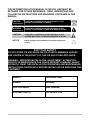
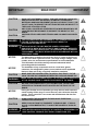
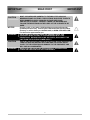
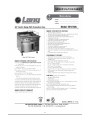
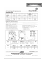
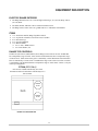
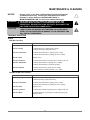
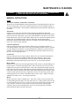
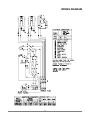
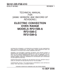
TM S6161-DR-FSE-010/34931
OPERATION AND SERVICE MANUAL
FOR
ELECTRIC CONVECTION OVEN RANGE
MODEL NUMBER 9P-RT36D-440VG (ALSO KNOWN AS RF21SM-A)
LANG MANUFACTURING COMPANY
A DIVISION OF STAR MANUFACTURING INTERNATIONAL
10 SUNNEN DR
ST. LOUIS, MO 63143
DISTRIBUTION STATEMENT
THIS PUBLICATION IS REQUIRED FOR OFFICIAL USE OR FOR ADMINISTRATIVE OR OPERATIONAL
PURPOSES. DISTRIBUTION IS LIMITED TO U.S. GOVERNMENT AGENCIES ONLY. OTHER REQUESTS FOR
THIS DOCUMENT MUST BE REFERRED TO COMMANDER NAVAL SEA SYSTEMS COMMAND, SEA 09,
WASHINGTON, DC 20362.
2M-W1095, Rev. -
May 16, 2007
S6161-DR-FSE-010/34931
MARCH 2001
IDENTIFYING TECHNICAL PUBLICATION SHEET
1.
2.
IDENTIFICATION DATA: LANG MFG. CO. MODEL 9D-RT36D-440VG (ALSO KNOWN AS RF21SM-A)
PURPOSE: THIS TECHNICAL PUBLICATION IS ISSUED FOR THE PURPOSE OF IDENTIFYING AN
AUTHORIZED TECHNICAL MANUAL FOR NAVY USE AND FOR PROVIDING SUPPLEMENTAL
TECHNICAL INFORMATION.
A. MANUFACTURER: LANG MFG. DIVISION OF STAR MANUFACTURING INTERNATIONAL
B. CONTRACT NUMBER: _________________________________
C. EQUIPMENT: ELECTRIC CONVECTION OVEN RANGE, MODEL NUMBER RF21SM-A
D. REQUISITION NUMBER: NOT REFERENCED
E. NATIONAL STOCK NUMBER (NSN): 7310-01-104-3349
F. TITLE: MAINTENANCE MANUAL FOR ELECTRIC CONVECTION OVEN RANGE MODEL NUMBER
RF21SM-A
G. DATE OF PUBLICATION: MARCH 2001
H. PREPARING ACTIVITY: DEFENSE GENERAL SUPPLY CENTER
I. APPLICABLE TMCR NUMBER: XXXX XXXXXX-XXX
J. EXTENT OF PROPOSED SUPPLEMENTAL DATA (10% MAXIMUM): 1%
K. LIST OF TECHNICAL MANUAL FOR THIS EQUIPMENT PROCURED UNDER ANOTHER CONTACT:
3. ADDITIONAL COPIES ARE AVAILABLE FROM:
NAVAL PUBLICATION AND FORMS CENTER
5801 TABOR AVE
PHILADELPHIA, PA 19120-5099
4. COVER: THE TECHNICAL MANUAL OUTSIDE COVER SHALL CONTAIN THE FOLLOWING STATEMENTS:
PUBLISHED BY DIRECTION OF COMMANDER, NAVAL SEA SYSTEMS COMMAND
THIS PUBLICATION IS REQUIRED FOR OFFICIAL USE OR FOR ADMINISTRATIVE OR OPERATIONAL
PURPOSES. DISTRIBUTION IS LIMITED TO U.S. GOVERNMENT AGENCIES ONLY. OTHER REQUESTS MUST
BE REFERRED TO COMMANDER, NAVAL SEA SYSTEMS COMMAND, SEA09, WASHINGTON, DC 20362
2
XXXXX-XX-XXX-XXX/XXXX
MARCH 2001
APPROVAL AND PROCUREMENT RECORD
APPROVAL DATA FOR: LANG ELECTRIC CONVECTION OVEN RANGE MODEL NUMBER RF21SM-A.
TITLE OF MANUAL: MAINTENANCE MANUAL FOR ELECTRIC CONVECTION OVEN RANGE MODEL
NUMBER RF21SM-A
APPROVAL AUTHORITY: NAVAL SHIP SYSTEMS ENGINEERING STATION
CONTRACT NUMBER
NSN
7310-01-104-3349
# OF UNITS
APL/CID
REMARKS:
DATE: MARCH 2001
CERTIFICATION:
IT IS HEREBY CERTIFIED THAT THE TECHNICAL MANUAL PROVIDED UNDER CONTRACT NUMBER
_______________________ FOR LANG RF21SM-A HAS BEEN APPROVED BY THE APPROVAL DATA SHOWN
ABOVE:
________________________________
DIRECTOR, GOV’T CONTRACTS
LANG MANUFACTURING COMPANY
FSCM / CAGE #: 34931
3
CHANGE RECORD
Change no.
Date
Title and/or Brief Description
4
Signature of Validating Officer
THE INFORMATION IN THIS MANUAL IS CRUCIAL AND MUST BE
RETAINED FOR FUTURE REFERENCE. READ, UNDERSTAND AND
FOLLOW THE INSTRUCTIONS AND WARNINGS CONTAINED IN THIS
MANUAL.
DANGER
POTENTIALLY HAZARDOUS SITUATION WHICH, IF NOT
AVOIDED, COULD RESULT IN DEATH.
WARNING
POTENTIALLY HAZARDOUS SITUATION WHICH, IF NOT
AVOIDED, COULD RESULT IN DEATH OR SERIOUS INJURY.
CAUTION
POTENTIALLY HAZARDOUS SITUATION WHICH, IF NOT
AVOIDED, MAY RESULT IN MINOR OR MODERATE INJURY.
NOTICE
Helpful operation and installation instructions and tips are
present.
FOR YOUR SAFETY
DO NOT STORE OR USE GASOLINE OR OTHER FLAMMABLE VAPORS
AND LIQUIDS IN THE VICINITY OF THIS OR ANY OTHER APPLIANCE.
WARNING: IMPROPER INSTALLATION, ADJUSTMENT, ALTERATION,
SERVICE OR MAINTENANCE CAN CAUSE PROPERTY DAMAGE, INJURY
OR DEATH. READ THE INSTALLATION, OPERATING AND MAINTENANCE
INSTRUCTIONS THOROUGHLY BEFORE INSTALLING OR SERVICING THIS
EQUIPMENT.
Model #:
Purchased From:
Serial #:
Location:
Date Purchased:
Date Installed:
Purchase Order #:
For Service, Call:
5
TABLE OF CONTENTS
CHAPTER
PAGE
1. TABLE OF CONTENTS..........................................................................6
2. LIST OF ILLUSTRATIONS .....................................................................7
3. READ FIRST ..........................................................................................8
4. SPECIFICATION SHEET .......................................................................11
5. EQUIPMENT DESCRIPTION .................................................................13
6. UNPACKING ..........................................................................................14
7. INSTALLATION ......................................................................................15
8. INITIAL START-UP.................................................................................16
9. OPERATION...........................................................................................17
10. MAINTENANCE & CLEANING ...............................................................18
11. ILLUSTRATED PARTS BREAK DOWN .................................................23
12. PARTS LIST ...........................................................................................29
13. WIRING DIAGRAM.................................................................................30
14. WARRANTY ...........................................................................................31
6
LIST OF ILLUSTRATIONS
PAGE
ILLUSTRATION
1. SPECIFICATION SHEET .......................................................................11
2. RANGE TOP CONFIGURATION............................................................13
3. LEG LAYOUT .........................................................................................14
4. ASSEMBLY ............................................................................................15
5. ILLUSTRATED PARTS BREAKDOWN ..................................................23
6. WIRING DIAGRAM.................................................................................30
7
IMPORTANT
CAUTION
CAUTION
CAUTION
READ FIRST
IMPORTANT
EACH UNIT IS EXTREMELY HEAVY. FOR SAFE HANDLING, INSTALLER
SHOULD OBTAIN HELP AS NEEDED, OR EMPLOY APPROPRIATE
MATERIALS HANDLING EQUIPMENT (SUCH AS A FORKLIFT, DOLLY, OR
PALLET JACK) TO REMOVE THE UNIT FROM THE SKID AND MOVE IT TO
THE PLACE OF INSTALLATION.
ANY STAND, COUNTER OR OTHER DEVICE ON WHICH RANGE WILL BE
LOCATED MUST BE DESIGNED TO SUPPORT THE WEIGHT OF THE
RANGE.
SHIPPING STRAPS ARE UNDER TENSION AND CAN SNAP BACK WHEN
CUT.
DANGER
THIS APPLIANCE MUST BE GROUNDED AT THE TERMINAL PROVIDED.
FAILURE TO GROUND THE APPLIANCE COULD RESULT IN
ELECTROCUTION AND DEATH.
WARNING
INSTALLATION OF THE UNIT MUST BE DONE BY PERSONNEL
QUALIFIED TO WORK WITH ELECTRICITY AND PLUMBING. IMPROPER
INSTALLATION CAN CAUSE INJURY TO PERSONNEL AND/OR DAMAGE
TO EQUIPMENT. UNIT MUST BE INSTALLED IN ACCORDANCE WITH ALL
APPLICABLE CODES.
NOTICE
The data plate is located on the serial tag, which is riveted to the front of
the unit in the lower right hand corner. The range voltage, wattage, serial
number, wire size, and clearance specifications are on the data plate.
This information should be carefully read and understood before
proceeding with the installation.
NOTICE
The installation of any components such as a vent hood, grease
extractors, fire extinguisher systems, must conform to their applicable
National, State and locally recognized installation standards.
MAKE SURE THE SIX WIRE LEADS TO SUPPLY ELECTRICITY TO THE
COOK TOP ARE NOT CRIMPED BETWEEN THE OVEN AND RANGE TOP.
CAUTION
WARNING
MAKE SURE THE MAIN POWER SUPPLY TO THE RANGE IS TURNED OFF
AT THE SOURCE PRIOR TO CONNECTING POWER TO THE RANGE.
CAUTION
BE SURE THE POWER SUPPLY VOLTAGE MATCHES THE VOLTAGE
SPECIFIED ON THE NAME-PLATE LOCATED ON THE FRONT OF THE
RANGE.
NOTICE
During the first few hours of operation you may notice a small amount of
smoke coming off the range, or out of the oven, and a faint odor from the
smoke. This is normal for a new range and will disappear after the first
few hours of use.
ALWAYS KEEP THE AREA NEAR THE APPLIANCE FREE FROM
COMBUSTIBLE MATERIALS.
CAUTION
CAUTION
KEEP FLOOR IN FRONT OF EQUIPMENT CLEAN AND DRY. IF SPILLS
OCCUR, CLEAN IMMEDIATELY, TO AVOID THE DANGER OF SLIPS OR
FALLS.
WARNING
KEEP WATER AND SOLUTIONS OUT OF CONTROLS. NEVER SPRAY OR
HOSE CONTROL CONSOLE, ELECTRICAL CONNECTIONS, ETC.
8
IMPORTANT
CAUTION
NOTICE
WARNING
CAUTION
WARNING
READ FIRST
IMPORTANT
MOST CLEANERS ARE HARMFUL TO THE SKIN, EYES, MUCOUS
MEMBRANES AND CLOTHING. PRECAUTIONS SHOULD BE TAKEN TO
WEAR RUBBER GLOVES, GOGGLES OR FACE SHIELD AND
PROTECTIVE CLOTHING. CAREFULLY READ THE WARNING AND
FOLLOW THE DIRECTIONS ON THE LABEL OF THE CLEANER TO BE
USED.
Service on this, or any other, LANG appliance must be performed by
qualified personnel only. Consult your LANG authorized service station
directory or call the factory at 1-800-807-9054, or WWW.STAR-MFG.COM
For the service agent nearest you.
BOTH HIGH AND LOW VOLTAGES ARE PRESENT INSIDE THIS
APPLIANCE WHEN THE UNIT IS PLUGGED/WIRED INTO A LIVE
RECEPTACLE. BEFORE REPLACING ANY PARTS, DISCONNECT THE
UNIT FROM THE ELECTRIC POWER SUPPLY.
USE OF ANY REPLACEMENT PARTS OTHER THAN THOSE SUPPLIED BY
LANG OR THEIR AUTHORIZED DISTRIBUTORS CAN CAUSE BODILY
INJURY TO THE OPERATOR AND DAMAGE TO THE EQUIPMENT AND
WILL VOID ALL WARRANTIES.
MAKE SURE THE RANGE HAS BEEN PROPERLY SECURED FROM
POWER BEFORE REMOVING ANY COMPONENTS.
9
LANG MANUFACTURING COMPANY
MANUAL FOR MODEL 9D-RT36A-440VG (ALSO KNOWN AS RF21SM-A)
ELECTRIC CONVECTION OVEN RANGE
ISSUED DATE: JULY 2001
LANG MANUFACTURING COMPANY
6500 MERRILL CREEK PARKWAY
EVERETT, WA 98203
ELECTRIC CONVECTION OVEN RANGE PER: MIL-X-XXXXXXXX
MIL SPEC
MIL-R-43954
LANG MODEL NUMBER
RF21SM-A
SPECIFIC NSN
7310-01-104-3349
* N.S.A. FOR “NAVAL SHIPBOARD APPLICATION”. ALL COMPONENTS WILL FIT THROUGH A 26”
WATERTIGHT HATCH.
10
SPECIFICATION SHEET
11
SPECIFICATION SHEET
12
EQUIPMENT DESCRIPTION
ELECTRIC RANGE EXTERIOR
¾
The Range dimensions are 30” (76.2cm) High (without legs), 38” (96.5cm) Deep, and 36”
(91.5cm) Wide.
¾
The Sides, Bottom, and Rear wall are constructed stainless steel.
¾
The Range surface comes with a 24” griddle and two 9” in diameter French Plates.
ITEMS
¾
¾
¾
¾
¾
1 ea. 9P-RT36A-440VG (Range Top) RF21-AM-U
1 ea. 9Q-FCOFL-AT440G (Convection Oven) F-6S-M-U
4 ea. Bolt down legs
2 ea. Operation Manuals
1 ea. Marine Handle
¾ 4 ea. ¼-20x½” HXD bolt S/S.
¾ 4 ea. Lock Washer, S/S
RANGE TOP CONTROLS
The RT36A (also known as RF21SM-A) Series Range comes with one 24”x24” Griddle that
has a temperature range of 100°F -450°F and two French Plates that have a temperature range
of 200°F-750°F. Each section of the grill is controlled by a 450°F thermostat and each French
Plate is controlled by a 6-heat switch. In addition the range comes with a convection oven that
is controlled by one thermostat that has a temperature range of 150°F-450°F. Below is a layout
of the top configuration.
RT36A (RF21SM-A)
One 24”x24” Griddle controlled by two 450°F
thermostats and two French Plates controlled by two 6heat switches.
FRENCH
PLATE
24" x 24"
GRIDDLE
FRENCH
PLATE
RANGE TOP CONFIGURATION
13
UNPACK-ING
CAUTION
CAUTION
CAUTION
EACH UNIT WEIGHS 600 LBS (THE TOP WEIGHS 410 LBS). FOR SAFE
HANDLING, INSTALLER SHOULD OBTAIN HELP AS NEEDED, OR
EMPLOY APPROPRIATE MATERIALS HANDLING EQUIPMENT (SUCH AS
A FORKLIFT, DOLLY, OR PALLET JACK) TO REMOVE THE UNIT FROM
THE SKID AND MOVE IT TO THE PLACE OF INSTALLATION.
ANY STAND, COUNTER OR OTHER DEVICE ON WHICH RANGE WILL BE
LOCATED MUST BE DESIGNED TO SUPPORT THE WEIGHT OF THE
RANGE.
SHIPPING STRAPS ARE UNDER TENSION AND CAN SNAP BACK WHEN
CUT.
RECEIVING THE OVEN
Upon receipt, check for freight damage, both visible and concealed. Visible damage
should be noted on the freight bill at the time of delivery and signed by the carrier's
agent. Concealed loss or damage means loss or damage, which does not become
apparent until the merchandise has been unpacked. If concealed loss or damage is
discovered upon unpacking, make a written request for inspection by the carrier's
agent within 15 days of delivery. All packing material should be kept for inspection.
Do not return damaged merchandise to Lang Manufacturing Company. File your
claim with the carrier.
LOCATION
Prior to un-crating, move the range as near its intended location as practical. The
crating will help protect the unit from the physical damage normally associated
with moving it through hallways and doorways.
UN-CRATING
The range will arrive in two packages, each inside a wood frame covered by
cardboard box and strapped to a skid. Remove the cardboard cover, cut the
straps and remove the wood frame. The oven may now be removed from the
skid.
INSTALLING THE LEGS
To install the legs, place some cardboard on the floor and gently tip the oven
portion of the range onto its back. A ½-13 threaded weld nut is provided in each of
the four corners of the oven. Thread each leg into the threaded weld nuts and lift
oven back onto the legs. (See leg layout below).
14
INSTALLATION
DANGER
THIS APPLIANCE MUST BE GROUNDED AT THE TERMINAL PROVIDED.
FAILURE TO GROUND THE APPLIANCE COULD RESULT IN
ELECTROCUTION AND DEATH.
WARNING
INSTALLATION OF THE UNIT MUST BE DONE BY PERSONNEL
QUALIFIED TO WORK WITH ELECTRICITY AND PLUMBING. IMPROPER
INSTALLATION CAN CAUSE INJURY TO PERSONNEL AND/OR DAMAGE
TO EQUIPMENT. UNIT MUST BE INSTALLED IN ACCORDANCE WITH ALL
APPLICABLE CODES.
NOTICE
The data plate is located on the serial tag, which is riveted to the front of
the unit in the lower right hand corner. The range voltage, wattage, serial
number, wire size, and clearance specifications are on the data plate.
This information should be carefully read and understood before
proceeding with the installation.
NOTICE
The installation of any components such as a vent hood, grease
extractors, fire extinguisher systems, must conform to their applicable
National, State and locally recognized installation standards.
ELECTRICAL CONNECTION
A 1¼” knockout is provided on the bottom left hand side of the oven below the
control panel for power connection.
The electrical connection must be made in accordance with local codes or in the
absence of local codes with National Electrical Code latest edition (in Canada
use: CSA STD. C22.1).
Place spacers, (ie. 2 x 4 wood block not supplied) at the front and rear of the oven
top.
Place the range top on the spacers (ie. 2 x 4 wood block not supplied) that are
located on top of the oven.
The six wire leads to supply electricity to the cook top are bundled under the front
bottom of the top. Route these wires through the bushing provided in the oven
top.
Align the four locating pins at the bottom corners of the Range bottom with the
four holes in each corner of the oven top.
Remove the spacers and lower the Range onto the oven.
CAUTION
MAKE SURE THE SIX WIRE LEADS TO SUPPLY ELECTRICITY TO THE
COOK TOP ARE NOT CRIMPED BETWEEN THE OVEN AND RANGE TOP.
WARNING
MAKE SURE THE MAIN POWER SUPPLY TO THE RANGE IS TURNED OFF
AT THE SOURCE PRIOR TO CONNECTING POWER TO THE RANGE.
The range can now be connected to power.
CAUTION
BE SURE THE POWER SUPPLY VOLTAGE MATCHES THE VOLTAGE
SPECIFIED ON THE NAMEPLATE LOCATED ON THE FRONT OF THE
RANGE.
Use the wiring diagram provided in this manual for determining the connections of
the cook top wires to the oven terminal block.
15
INITIAL START-UP
INITIAL PREHEAT
Prior to putting any range or oven into full time operation at normal cooking
temperatures, it must be thoroughly dried out. Moisture absorption in the closed
spaces, in the insulation, and even inside the heating elements can cause future
trouble if not properly treated.
Griddles
To “dry out” the griddle, set the thermostat to 250°F. Allow the unit to operate at
least 15 minutes at this heat level. Set the thermostat to 350°F and allow another 15
minutes to elapse. Set the thermostat to 450°F and allow the unit to maintain the
temperature for a minimum of 4 hours. More time may be required if the unit has to
operate in a moist environment.
If the unit is out of use for three or more days, a one-hour preheat schedule should be
used, especially when exposed to high humidity and/or cool temperatures.
Before any griddle plate can be put into full operation it will need to be properly
seasoned. To do this, turn the griddle to 200°F and wait for the red heat indicator
lamp to shut off. Once the indicator lamp has shut off, apply a thin coat of highgrade, non-salted vegetable oil t the griddle surface with a metal spatula or towel.
Wait approximately five minutes and re-coat any dry spots. Repeat this procedure at
300°F and at 400°F.
French Plates
To “dry out” the French plates, set the 6-heat switch to position three. Allow the unit
to operate at least 15 minutes at this heat level. Set the 6-heat switch to position four
and allow another 15 minutes to elapse. Set the 6-heat to position six and allow the
unit to maintain the temperature for a minimum of 4 hours. More time may be
required if the unit has to operate in a moist environment.
If the unit is out of use for three or more days, a one-hour preheat schedule should be
used, especially when exposed to high humidity and/or cool temperatures.
Ovens
To “dry out” the oven, set the thermostat to 250°F and turn on the power switch.
Allow the unit to operate at least 15 minutes at this heat level. Set the thermostat to
350°F and allow another 15 minutes to elapse. Set the thermostat to 450°F and allow
the unit to maintain the temperature for a minimum of 4 hours. More time may be
required if the unit has to operate in a moist environment.
If the unit is out of use for three or more days, a one-hour preheat schedule should be
used, especially when exposed to high humidity and/or cool temperatures.
16
OPERATION
NOTICE
During the first few hours of operation you may notice a small amount of
smoke coming off the range, or out of the oven, and a faint odor from the
smoke. This is normal for a new range and will disappear after the first
few hours of use.
OVEN
The convection oven roasts and bakes in shorter time and at lower temperatures with less
shrinkage than conventional commercial ovens.
A blower in the Lang convection oven circulates air within the chamber to heat the entire space
evenly and transfer heat efficiently to the product, even with stacked loading.
The airflow continuously removes the thick layer of moist, cool air that otherwise would
surround the product. When properly loaded and operated, it maintains this airflow throughout
the chamber to eliminate hot spots and roasts or bakes with minimum power consumption at
twice the output capacity of a conventional oven.
The power switch on the lower portion of the control panel energizes the fan motor and
activates the thermostatically controlled circuit for the oven heating elements. When this
switch is in the on position, the red indicator light will illuminate.
Rotating the thermostat control knob from "off" position to selected temperature causes the
indicator light to illuminate and closes the contactor that feeds power to the heating elements.
This light will cycle "on and off" as the thermostat calls for heat in the oven. The blower,
however, operates continuously while the power switch is in the "on" position.
The black control knob operates a damper in the oven vent stack. The damper is open when
knob is pulled outward.
Circuit breakers behind the control panel protect the electrical components from overload.
Griddle
Thermostats control 24” x 24” grill plate.
Temperature ranges from 100°-450°F.
Recommended: All heavy and light frying.
Set the thermostat dial at the desired temperature and allow for a thirty-minute preheat time.
The red indicator light will be on until the desired temperature is reached and then shut off.
The pilot light will cycle on and off as the elements cycle on and off.
French Plate
6-heat switch controls one, French Plate.
Temperature settings range from 1(low) to 6(high).
Recommended: Light duty sauce pans and small stockpots.
Not Recommended: Heavy stock pots, or heavy urns, or kettles.
Set the 6-heat dial to the desired setting and allow for a thirty-minute preheat time.
17
MAINTENANCE & CLEANING
CAUTION
ALWAYS KEEP THE AREA NEAR THE APPLIANCE FREE FROM
COMBUSTIBLE MATERIALS.
CAUTION
KEEP FLOOR IN FRONT OF EQUIPMENT CLEAN AND DRY. IF SPILLS
OCCUR, CLEAN IMMEDIATELY, TO AVOID THE DANGER OF SLIPS OR
FALLS.
WARNING
CAUTION
KEEP WATER AND SOLUTIONS OUT OF CONTROLS. NEVER SPRAY OR
HOSE CONTROL CONSOLE, ELECTRICAL CONNECTIONS, ETC.
MOST CLEANERS ARE HARMFUL TO THE SKIN, EYES, MUCOUS
MEMBRANES AND CLOTHING. PRECAUTIONS SHOULD BE TAKEN TO
WEAR RUBBER GLOVES, GOGGLES OR FACE SHIELD AND
PROTECTIVE CLOTHING. CAREFULLY READ THE WARNING AND
FOLLOW THE DIRECTIONS ON THE LABEL OF THE CLEANER TO BE
USED.
CLEANING
•
•
Always start with a cold range.
The stainless exterior can easily be cleaned using Lang Mfg. Prime Shine
(72804-41) oven cleaner.
• Always follow the cleaner manufacturer's instructions when using any cleaner.
• Care should be taken to prevent caustic cleaning compounds from coming in
contact with the aluminized blower wheel and aluminized inside of the oven.
• Discoloration or heat tint may be removed using Lang Mfg. Carbon Release
(72804-32) oven cleaner.
Always apply these cleaners when the oven is cold and rub in the direction of the
metal's grain
The range should be thoroughly cleaned at least once a week in addition to the
normal daily cleaning to insure against the accumulation of foreign material.
Keep drip pans under range top plates clean.
Keep hot plate and french plate surfaces clean.
Outside of range and top should be kept clean.
Electric equipment is inherently clean and sanitary, but may become unsanitary if
grease is allowed to accumulate on it. Take advantage of the clean, sanitary features
of electric equipment, give it the regular attention that it deserves the same as any
other highly perfected machinery, to insure best results and continued high operating
efficiency.
EMERGENCY LOCKOUT
Locate power disconnect at source and remove power from range.
LONG TERM STORAGE
Secure range from power.
Apply a generous amount of Lang Mfg. Prima Shine (72804-41) to the stainless
steel.
Apply a generous amount of Lang Mfg. Shipping Preservative Grease (72804-08) to
the hop plate surface and the French plate surface.
18
MAINTENANCE & CLEANING
NOTICE
WARNING
CAUTION
Service on this, or any other, LANG appliance must be performed by
qualified personnel only. Consult your authorized service station
directory or call the factory at 1-800-224-LANG (5264), or
WWW.LANGWORLD.COM For the service station nearest you.
BOTH HIGH AND LOW VOLTAGES ARE PRESENT INSIDE THIS
APPLIANCE WHEN THE UNIT IS PLUGGED/WIRED INTO A LIVE
RECEPTACLE. BEFORE REPLACING ANY PARTS, DISCONNECT THE
UNIT FROM THE ELECTRIC POWER SUPPLY.
USE OF ANY REPLACEMENT PARTS OTHER THAN THOSE SUPPLIED BY
LANG OR THEIR AUTHORIZED DISTRIBUTORS CAN CAUSE BODILY
INJURY TO THE OPERATOR AND DAMAGE TO THE EQUIPMENT AND
WILL VOID ALL WARRANTIES.
TROUBLE SHOOTING
OVEN
OVEN WILL NOT HEAT
PROBABLE CAUSE
Oven circuit breaker not on
CORRECTIVE ACTION
Cycle breaker to the “ON” position.
Incorrect wiring
Confirm that oven is getting proper voltage.
Confirm that range is phased correctly.
Defective transformer
Confirm that transformer is getting correct voltage.
Confirm that transformer is putting out correct voltage.
Defective Fuses
Replace fuses.
Defective Contactor
Confirm that contactor is getting correct voltage on the coil.
Defective Thermostat
Confirm that thermostat is getting correct voltage.
Confirm that thermostat is operating properly.
Defective Element
Confirm that element is getting correct voltage
Check element for normal operation. (11.5 Amps )
OVEN MOTOR WILL NOT COME ON
PROBABLE CAUSE
Incorrect wiring
CORRECTIVE ACTION
Confirm that oven is getting proper voltage.
Confirm that range is phased correctly.
Defective transformer
Confirm that transformer is getting correct voltage.
Confirm that transformer is putting out correct voltage.
Defective Fuses
Replace fuses.
Defective Contactor
Confirm that contactor is getting correct voltage on the coil.
Defective Motor
Confirm that motor is getting power and working properly.
Replace Motor.
19
MAINTENANCE & CLEANING
RANGE
Griddle
GRIDDLE WILL NOT HEAT
PROBABLE CAUSE
Incorrect wiring
CORRECTIVE ACTION
Confirm that oven is getting proper voltage.
Confirm that range is phased correctly.
Oven circuit breaker not on
Cycle breaker to the “ON” position.
Defective Thermostat
Confirm that thermostat is getting correct voltage.
Confirm that thermostat is operating properly.
Defective Element
Confirm that element is getting correct voltage
Check element for normal operation (Inside 5.7 Amps, Outside 3.5
Amps).
FRENCH PLATE
FRENCH PLATE WILL NOT HEAT
PROBABLE CAUSE
Incorrect wiring
CORRECTIVE ACTION
Confirm the French Plate is wired correctly.
Confirm that range is phased correctly.
Defective 6-Heat switch
Confirm that switch is wired correctly.
Confirm that switch is operating correctly.
Defective French Plate
Confirm that French Plate is getting correct voltage.
Confirm that French Plate is operating correctly. (See Technical Data)
CALIBRATION
Calibration Check
Place thermometer or thermocouple in the center of oven cavity or grill section.
Set thermostat to 350°F.
Allow the oven or grill to preheat for at least half an hour.
Note cycle on temperatures and cycle off temperatures for 3 cycles. (Red indicator light indicates
when oven is calling for heat)
After 3 cycles average the temperature, (Add all six temperatures and divide by 6) The
temperature should be +/- 15°F.
Calibration Adjustment
A 1/16” flat blade screwdriver with a 2” shaft is required to make adjustments on the thermostat.
Maintain the oven temperature at 350°F.
Without turning the thermostat, remove the knob.
Locate the adjustment screw at the base of the shaft and insert the screwdriver.
Grasp the shaft and turn the screw. Counter clockwise to increase and clockwise to decrease (1/8
of a turn will move the temperature 5-7 °F in either direction).
Reinstall the oven knob and recheck the oven temperature.
20
MAINTENANCE & CLEANING
WARNING
MAKE SURE THE RANGE HAS BEEN PROPERLY SECURED FROM
POWER BEFORE REMOVING ANY COMPONENTS.
REMOVAL INSTRUCTIONS
OVEN
Thermostat, Contactor, Transformer, and Switch
These parts are located behind the control panel assembly on the right hand side of the oven.
To access control panel, remove the vent knob and the seven screws around the outside of
the control panel assembly. Slowly pull the control panel toward you until the component is
accessible.
Thermostat
Inside the oven, remove the fan baffle and the retaining clips holding the thermostat
capillary tube to the inside of the oven. Feed the bulb through the oven wall into the control
panel area. Pull out control panel as previously outlined. Remove knob and two screws that
hold the thermostat to the oven control panel. Remove the wires from the old thermostat and
attach to the corresponding terminal of the new thermostat. Discard old thermostat.
Reinstall the thermostat and capillary tube into oven and the control panel and restore power
to the oven. Test for proper operation.
Contactor and Switch
Pull out control panel as previously outlined. Remove the wires from the contactor or
switch being changed. Place those wires on the corresponding terminal of the new contactor
or switch. Remove old contactor or switch and mount new contactor or switch with wires
attached. Discard old contactor or switch. Reinstall the control panel and restore power to
the oven. Test for proper operation.
Transformer
Pull out control panel as previously outlined. Remove the wires from the old transformer.
Place the wires on the corresponding terminal of the new transformer. Remove old
transformer and mount new transformer with wires attached. Discard old transformer.
Reinstall the control panel and restore power to the oven. Test for proper operation.
Blower Wheel
Inside the oven, remove the racks and right hand rack slide. Remove wing nut holding oven
baffle. Remove oven baffle exposing the blower wheel. Loosen the two 1/4-20-set screws
holding the blower wheel to the motor shaft. Using a three-fingered wheel puller, grasp the
puller ring with all three fingers and tighten the puller until the blower wheel hub clears the
motor shaft. Place new blower-wheel on the motor shaft and position the new blower wheel
so that it is flush with front inlet ring. Tighten the set-screw over the flat spot on the motor
shaft and spin the blower wheel to confirm that blower wheel is strait. Adjust if necessary
and tighten second set screw. Test for proper operation.
Motor
Remove the blower wheel as outlined above. Once blower wheel is removed, remove the
six bolts holding the motor plate to the side wall of the oven. Gently pull the motor out and
lay on the bottom of the oven cavity. Note each wire location on the motor and remove the
wires. Remove motor from cavity and remove old motor from motor mounting plate.
Attach new motor to motor mounting plate. Reverse removal instructions to assemble.
Discard old motor and test for proper operation.
21
MAINTENANCE & CLEANING
REMOVAL INSTRUCTIONS
OVEN CONTINUED
Elements
Remove oven racks and right hand rack slide from oven. Remove the wing nuts holding oven
baffle to right hand of oven. Remove oven baffle from oven. Remove 4 screws holding oven
elements to right hand of oven. Gently pull elements away from right hand of oven. Noting
wire locations, disconnect wires from element. Discard old element. Reverse removal
instructions to assemble.
RANGE TOP
Thermostat
Secure range top from power. Open front control panel and feed capillary tube up towards grill
plate. Using two 9” braces, lift the griddle plate up and secure with the two 9” braces. Remove
capillary tube holders from the center of the element pan assembly and gently remove from
griddle area. Remove two sheet metal screws holding control panel to range top and remove
control panel. Remove the thermostat knob and two screws holding the thermostat to the
control panel. Discard old thermostat. Reverse removal instructions to install new thermostat.
Elements
Secure range top from power. Using two 9” braces, lift the griddle plate up and secure with the
two 9” braces. Remove capillary tube holders from the center of the element pan assembly and
gently remove from griddle area. Remove wires from element terminals, noting the wire
locations. Remove the five nuts holding the element pan assembly to the bottom of the griddle.
Remove defective element from the element pan and discard defective element. To install
reverse removal instructions.
6-Heat Switch
Secure range top from power. Remove two sheet metal screws holding control panel to range
top and remove control panel. Remove the 6-heat switch knob and two screws holding the 6heat switch to the control panel. Remove wires from the 6-heat switch terminals noting the wire
locations. Discard old 6-heat switch. Reverse removal instructions.
French Plate
Secure range top from power. Using two 9” braces, lift the French plate frame assembly up and
secure with the two 9” braces. Remove wires from the element terminals, noting the wire
locations. Remove defective French plate assembly from the range. To install reverse removal
instructions.
22
ILLUSTRATED PART BREAKDOWN
23
ILLUSTRATED PARTS BREAKDOWN
24
ILLUSTRATED PARTS BREAKDOWN
25
ILLUSTRATED PARTS BREAKDOWN
34
26
ILLUSTRATED PARTS BREAKDOWN
27
ILLUSTRATED PARTS BREAKDOWN
28
PARTS LIST
Item #
21
22
23
24
25
26
27
28
29
30
31
32
33
34
35
36
37
38
39
40
41
42
43
44
45
46
47
48
49
50
51
52
53
Description
Range Plate Assembly 1/2” x 3ft
Element (Griddle) 440V I/S 3000 Watts
Element (Griddle) 440V O/S 2000 Watts
Element Pan Assembly w/ Snout
Wire Bracket
Thermostat Capillary Tube Holder
Element Terminal Guard
Indicator Light 440V
Knob Thermostat 450°F Griddle
Terminal Block 3 Pole
Thermostat 450°F Griddle
French Plate Assembly, 480V, 2600 Watt
6-Heat Switch
Thermostat 850°F
French Plate Frame Assembly
Ship Rail 90° 13”
Ship Rail Hooked 11⅜”
Ship Rail Hooked 32¼”
Ship Rail Socket
Ship Rail Socket
Knob 6-heat switch
Range Top Control Panel Front
Range Top Front
Pan / Grease Drawer
Grab Bar Assembly 36” Long
Marine Pan Latch Assembly
Range Top Left Hand Assembly
Range Top Center Channel
Range Top Right Hand Assembly
Range Top Rear Assembly
Fuse Holder 15 Amp
Switch Toggle On-Off
Knob Manual Timer
Knob Damper Black
Knob Thermostat 450°F Oven
Pilot Light 208/240V
Thermostat 450°F Oven
Timer Mechanical Long Ring
Contactor 2 Pole 208/240 VAC
Contactor 3 Pole 208/240 VAC
Circuit Breaker 440 Volt 3 Pole
Transformer 440/240 VAC
Circuit Breaker 440 Volt 2/10 Amp 2 Pole
Fuse 15 Amp
Motor 1/3 HP 440 Volt
Motor Mount Assembly
Baffle Deflector
Insulation R/H
Insulation Rear
Can R/H side
Blower Wheel
Element (Oven) 440 Volt 6000 Watts
Baffle
Hinge Bracket, Lower Left (Oven)
Door Handle 11 1/2” Long Black
Door Outer Skin
Door Insulation
Door Inner Skin
Door Micro switch assembly
Door Stop & Slide
Hinge Bracket, Upper Left (Oven)
Hinge Pin
Hinge Plate & Bushing (Door)
Complete Door Assembly
Lang Part #
50401-03
11010-24
11010-23
50300-20
50306-25
60102-17
50306-33
31601-02
70701-16
30500-07
30402-08
11120-14
30304-09
30402-23
50300-82
50900-01
50901-01
50901-04
50902-03
50902-05
70701-41
RF21-306-1
RF21-711
RF21-705
50300-44
60102-93
RF21-710
RF21-704
RF21-709
RF21-703
30901-02
30303-06
70701-09
70701-25
70701-19
31601-01
30402-27
30801-01
30701-02
30700-05
31800-04
31400-04
31800-07
30900-01
30200-03
F6-188
F6-123-1
F6-158
F6-251
F6-104-5
71500-03
11090-11
F6-122-1
70601-28
50800-12
F6-145
F6-144-1
F6-144-6
60102-1661
50301-50
70601-27
70601-06
70601-05
60102-2031
29
Vendor
Lang Mfg.
Caloritech
Caloritech
Lang Mfg.
Lang Mfg.
Lang Mfg.
Lang Mfg.
Wes-Grade
Lang Mfg.
All-West Fasteners
Invensys
E.G.O. Products
E.G.O. Products
Invensys
Lang Mfg.
Lang Mfg.
Lang Mfg.
Lang Mfg.
Lang Mfg.
Lang Mfg.
Lang Mfg.
Lang Mfg.
Lang Mfg.
Lang Mfg.
Lang Mfg.
Lang Mfg.
Lang Mfg.
Lang Mfg.
Lang Mfg.
Lang Mfg.
H.D. Campbell
Carling Tech
Lang Mfg
Reid Tool
Lang Mfg
Wes-Grade
Invensys
M.H. Rhodes
Products Unltd
Products Unltd
Carling Tech
Argo Inter’l
Carling Tech
H.D. Campbell
Merkle-Korff
Lang Mfg.
Lang Mfg.
Lang Mfg.
Lang Mfg.
Lang Mfg.
Revcor Inc
Caloritech
Lang Mfg.
Kason Ind
Prodeco
Lang Mfg.
Lang Mfg.
Lang Mfg.
Lang Mfg.
Lang Mfg.
Kason Ind
Kason Ind
Kason Ind
Lang Mfg.
Vendor #
50401-03
1x1-11216-02
1x1-11217-02
50300-20
50306-25
60102-17
50306-33
1854-1-20-20310
70701-16
162-04-3L
SP-173-72
12.22454.484
49.27214.500
KNP-5-48
50300-82
50900-01
50901-01
50901-04
50902-03
50902-05
70701-41
RF21-305-1
RF21-711
RF21-705
50300-20
60102-93
RF21-710
RF21-704
RF21-709
RF21-703
HKP-H-H Bussman
2GL231-78-XLN2
70701-09
DK-49-Reid
70701-19
2152-1-23-20110
KXP-356-48
220012
3100-20U3198
3100-30U8198LM
EA3X00191832CHB
HD/2221109T00
CB3B02422022CC
ABC-15
101356.00
F6-188
F6-123-1
F6-158
F6-251
F6-104-5
1-7981
1x1-11090-11
F6-122-1
91510004080035C
50800-12
F6-145
F6-144-1
F6-144-6
60102-1661
50301-50
91511005100035C
915230005410033F
9152300050
60102-2031
WIRING DIAGRAM
30
Lang Manufacturing Limited Warranty to Commercial Purchasers*
(Contiguous U.S. Including Hawaii, Alaska & **Canada.)
Lang Manufacturing Equipment (“Lang Equipment”)
has been skillfully manufactured, carefully inspected
and packaged to meet rigid standards of excellence.
Lang warrants its Equipment to be free from defects in
material and workmanship for (12) twelve consecutive
months. Exception: School Food Services for (36)
Thirty-six consecutive months effective June 1, 2001,
for all full size convection ovens with AP or AT
controllers, with the following conditions and subject to
the following limitations.
I. This parts and labor warranty is limited to Lang
Equipment sold to the original commercial
purchaser/users (but not original equipment
manufacturers), at its original place of installation, in
the continental United States, Hawaii and Canada.
Quartz elements are warranted for ninety (90) days from
the date of installation.
II. Damage during shipment is to be reported to the
carrier, is not covered under this warranty, and is the
sole responsibility of purchaser/user.
III. Lang, or an authorized service representative, will
repair or replace, at Lang’s sole election, and Lang
Equipment, including but not limited to, safety valves,
gas and electric components, found to be defective
during the warranty period. As to warranty service in
the territory described above, Lang will absorb labor
and portal to portal transportation costs (time &
mileage) for the first (12) twelve months from the date
of installation or eighteen (18) months from date of
shipment from Lang Manufacturing, which ever comes
first.
*Canada warranty paid in US dollars based on
current exchange rates
IV. This warranty does not cover routine general
maintenance, periodic adjustments, as specified in
operating instructions or manuals, and consumable parts
such as quartz elements, or labor costs incurred for
removal of adjacent equipment or objects to gain access
to Lang Equipment. This warranty does not cover
defects caused by improper installation, abuse, careless
operation, or improper maintenance of equipment.
V. THIS WARRANTY IS EXCLUSIVE AND IS IN
LIEU OF ALL OTHER WARRANTIES, EXPRESSED
OR IMPLIED, INCLUDING ANY IMPLIED
WARRANTY OF MERCHANTABILITY OR
FITNESS FOR A PARTICULAR PURPOSE, EACH
OF WHICH IS HEREBY EXPRESSLY
DISCLAIMED. THE REMEDIES DESCRIBED
ABOVE ARE EXCLUSIVE AND IN NO EVENT
SHALL LANG BE LIABLE FOR SPECIAL,
CONSEQUENTIAL OR INCIDENTAL DAMAGES
FOR THE BREACH OR DELAY IN PERFORMANCE
OF THIS WARRANTY.
VI. Lang Equipment is for commercial use only. If sold
as a component of another (OEM) manufacturer’s
equipment, or if used as a consumer product, such
Equipment is sold AS IS and without any warranty.
STAR MANUFACTURING
10 Sunnen Drive, St. Louis, MO 63143 U.S.A.
(800) 807-9054
(314) 781-2777
Parts & Service (800) 807-9054
www.star-mfg.com