1
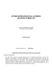
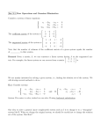
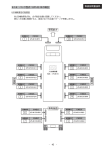
TM XXXXX-XX-XXX-XXX/XXXXX XXXX-XX-XXX-XXXX OPERATION AND SERVICE MANUAL FOR SUBMARINE ELECTRIC CONVECTION OVEN RANGE MODEL NUMBER RF21SMG-USUB LANG MANUFACTURING COMPANY 6500 MERRILL CREEK PARKWAY EVERETT, WA 98203 DISTRIBUTION STATEMENT THIS PUBLICATION IS REQUIRED FOR OFFICIAL USE OR FOR ADMINISTRATIVE OR OPERATIONAL PURPOSES. DISTRIBUTION IS LIMITED TO U.S. GOVERNMENT AGENCIES ONLY. OTHER REQUESTS FOR THIS DOCUMENT MUST BE REFERRED TO COMMANDER NAVAL SEA SYSTEMS COMMAND, SEA 09, WASHINGTON, DC 20362. XXXXX-XX-XXX-XXX/XXXX MARCH 2001 IDENTIFYING TECHNICAL PUBLICATION SHEET 1. 2. IDENTIFICATION DATA: LANG MFG. CO. MODEL RF21SMG-USUB PURPOSE: THIS TECHNICAL PUBLICATION IS ISSUED FOR THE PURPOSE OF IDENTIFYING AN AUTHORIZED TECHNICAL MANUAL FOR NAVY USE AND FOR PROVIDING SUPPLEMENTAL TECHNICAL INFORMATION. A. MANUFACTURER: LANG MFG. CO. B. CONTRACT NUMBER: XXXXXX-XX-X-XXXX C. EQUIPMENT: ELECTRIC CONVECTION OVEN RANGE, MODEL NUMBER RF21SMG-USUB D. REQUISITION NUMBER: NOT REFERENCED E. NATIONAL STOCK NUMBER (NSN): XXXX-XX-XXX-XXXX F. TITLE: MAINTENANCE MANUAL FOR ELECTRIC CONVECTION OVEN RANGE MODEL NUMBER RF21SMG-USUB G. DATE OF PUBLICATION: MARCH 2001 H. PREPARING ACTIVITY: DEFENSE GENERAL SUPPLY CENTER I. APPLICABLE TMCR NUMBER: XXXX XXXXXX-XXX J. EXTENT OF PROPOSED SUPPLEMENTAL DATA (10% MAXIMUM): 1% K. LIST OF TECHNICAL MANUAL FOR THIS EQUIPMENT PROCURED UNDER ANOTHER CONTACT: 3. ADDITIONAL COPIES ARE AVAILABLE FROM: NAVAL PUBLICATION AND FORMS CENTER 5801 TABOR AVE PHILADELPHIA, PA 19120-5099 4. COVER: THE TECHNICAL MANUAL OUTSIDE COVER SHALL CONTAIN THE FOLLOWING STATEMENTS: PUBLISHED BY DIRECTION OF COMMANDER, NAVAL SEA SYSTEMS COMMAND THIS PUBLICATION IS REQUIRED FOR OFFICIAL USE OR FOR ADMINISTRATIVE OR OPERATIONAL PURPOSES. DISTRIBUTION IS LIMITED TO U.S. GOVERNMENT AGENCIES ONLY. OTHER REQUESTS MUST BE REFERRED TO COMMANDER, NAVAL SEA SYSTEMS COMMAND, SEA09, WASHINGTON, DC 20362 2 XXXXX-XX-XXX-XXX/XXXX MARCH 2001 APPROVAL AND PROCUREMENT RECORD APPROVAL DATA FOR: LANG ELECTRIC CONVECTION OVEN RANGE MODEL NUMBER RF21SMGUSUB. TITLE OF MANUAL: MAINTENANCE MANUAL FOR ELECTRIC CONVECTION OVEN RANGE MODEL NUMBER RF21SMG-USUB APPROVAL AUTHORITY: NAVAL SHIP SYSTEMS ENGINEERING STATION CONTRACT NUMBER NSN # OF UNITS APL/CID REMARKS: DATE: MARCH 2001 CERTIFICATION: IT IS HEREBY CERTIFIED THAT THE TECHNICAL MANUAL PROVIDED UNDER CONTRACT NUMBER XXXXXX-XX-X-XXXX FOR LANG RF21SMG-USUB HAS BEEN APPROVED BY THE APPROVAL DATA SHOWN ABOVE: ________________________________ DIRECTOR, GOV’T CONTRACTS LANG MANUFACTURING COMPANY FSCM / CAGE #: 34931 3 CHANGE RECORD Change no. Date Title and/or Brief Description 4 Signature of Validating Officer TABLE OF CONTENTS CHAPTER PAGE 1. TABLE OF CONTENTS ..........................................................................5 2. LIST OF ILLUSTRATIONS......................................................................6 3. READ FIRST...........................................................................................7 4. SPECIFICATION SHEET........................................................................10 5. EQUIPMENT DESCRIPTION .................................................................12 6. ASSEMBLY INSTRUCTIONS .................................................................13 7. INSTALLATION.......................................................................................18 8. INITIAL START-UP .................................................................................19 9. OPERATION ...........................................................................................20 10. MAINTENANCE & CLEANING ...............................................................21 11. ILLUSTRATED PARTS BREAK DOWN..................................................25 12. PARTS LIST............................................................................................31 13. WIRING DIAGRAM .................................................................................32 14. WARRANTY............................................................................................33 5 LIST OF ILLUSTRATIONS ILLUSTRATION PAGE 1. SPECIFICATION SHEET........................................................................10 2. RANGE TOP CONFIGURATION ............................................................12 3. OVEN ASSEMBLY..................................................................................16 4. RANGE TOP ASSEMBLY.......................................................................17 5. ILLUSTRATED PARTS BREAKDOWN...................................................25 6 IMPORTANT CAUTION: CAUTION: CAUTION: DANGER: WARNING: NOTICE: NOTICE: NOTICE: CAUTION: CAUTION: READ FIRST EACH UNIT WEIGHS 600 LBS (THE TOP ONLY WEIGHS 410 LBS). FOR SAFE HANDLING, INSTALLER SHOULD OBTAIN HELP AS NEEDED, OR EMPLOY APPROPRIATE MATERIALS HANDLING EQUIPMENT (SUCH AS A FORKLIFT, DOLLY, OR PALLET JACK) TO REMOVE THE UNIT FROM THE SKID AND MOVE IT TO THE PLACE OF INSTALLATION. ANY STAND, COUNTER OR OTHER DEVICE ON WHICH RANGE WILL BE LOCATED MUST BE DESIGNED TO SUPPORT THE WEIGHT OF THE RANGE. SHIPPING STRAPS ARE UNDER TENSION AND CAN SNAP BACK WHEN CUT. THIS APPLIANCE MUST BE GROUNDED AT THE TERMINAL PROVIDED. FAILURE TO GROUND THE APPLIANCE COULD RESULT IN ELECTROCUTION AND DEATH. INSTALLATION OF THE UNIT MUST BE DONE BY PERSONNEL QUALIFIED TO WORK WITH ELECTRICITY. IMPROPER INSTALLATION CAN CAUSE INJURY TO PERSONNEL AND/OR DAMAGE TO EQUIPMENT. UNIT MUST BE INSTALLED IN ACCORDANCE WITH ALL APPLICABLE CODES. The data plate is located right of range top controls and behind circuit breaker door on oven. The range voltage, wattage, serial number, wire size, and clearance specifications are on the data plate. This information should be carefully read and understood before proceeding with the installation. The installation of any components such as a vent hood, grease extractors, fire extinguisher systems, must conform to their applicable National, State and locally recognized installation standards. During the first few hours of operation you may notice a small amount of smoke coming off the range, or out of the oven, and a faint odor from the smoke. This is normal for a new range and will disappear after the first few hours of use. ALWAYS KEEP THE AREA NEAR THE APPLIANCE FREE FROM COMBUSTIBLE MATERIALS. KEEP FLOOR IN FRONT OF EQUIPMENT CLEAN AND DRY. IF SPILLS OCCUR, CLEAN IMMEDIATELY, TO AVOID THE DANGER OF SLIPS OR FALLS. 7 IMPORTANT IMPORTANT READ FIRST WARNING: KEEP WATER AND SOLUTIONS OUT OF CONTROLS. NEVER SPRAY OR HOSE CONTROL CONSOLE, ELECTRICAL CONNECTIONS, ETC. CAUTION: MOST CLEANERS ARE HARMFUL TO THE SKIN, EYES, MUCOUS MEMBRANES AND CLOTHING. PRECAUTIONS SHOULD BE TAKEN TO WEAR RUBBER GLOVES, GOGGLES OR FACE SHIELD AND PROTECTIVE CLOTHING. CAREFULLY READ THE WARNING AND FOLLOW THE DIRECTIONS ON THE LABEL OF THE CLEANER TO BE USED. Service on this, or any other, LANG appliance must be performed by qualified personnel only. Consult your authorized service station directory or call the factory at 1-800-224-LANG (5264), or WWW.LANGWORLD.COM for the service station nearest you. BOTH HIGH AND LOW VOLTAGES ARE PRESENT INSIDE THIS APPLIANCE WHEN THE UNIT IS PLUGGED/WIRED INTO A LIVE RECEPTACLE. BEFORE REPLACING ANY PARTS, DISCONNECT THE UNIT FROM THE ELECTRIC POWER SUPPLY. USE OF ANY REPLACEMENT PARTS OTHER THAN THOSE SUPPLIED BY LANG OR THEIR AUTHORIZED DISTRIBUTORS CAN CAUSE BODILY INJURY TO THE OPERATOR AND DAMAGE TO THE EQUIPMENT AND WILL VOID ALL WARRANTIES. NOTICE: WARNING: CAUTION: 8 IMPORTANT LANG MANUFACTURING COMPANY MANUAL FOR MODEL RF21SMG-USUB ELECTRIC CONVECTION OVEN RANGE ISSUED DATE: JULY 2001 LANG MANUFACTURING COMPANY 6500 MERRILL CREEK PARKWAY EVERETT, WA 98203 ELECTRIC CONVECTION OVEN RANGE PER: MIL-X-XXXXXXXX MIL SPEC TYPE I, SIZE 1 LANG MODEL NUMBER RF21SMG-USUB SPECIFIC NSN XXXX-XX-XXX-XXXX * N.S.A. FOR “NAVAL SHIPBOARD APPLICATION”. ALL COMPONENTS WILL FIT THROUGH A 26” WATER TIGHT HATCH. 9 SPECIFICATION SHEET 10 SPECIFICATION SHEET 11 EQUIPMENT DESCRIPTION ELECTRIC RANGE EXTERIOR ¾ The Range dimensions are 30” (76.2cm) High, 38” (96.5cm) Deep, and 36” (91.5cm) Wide. ¾ The Sides, Bottom, and Rear wall are constructed stainless steel. ¾ The Range surface comes with a 36” griddle. ITEMS ¾ ¾ ¾ ¾ ¾ ¾ 1 ea. RF21-GM-USUB (Range Top) 1 ea. F-6S-M-U-SUB (Convection Oven) 4 ea. Bolt down legs 2 ea. Operation Manuals 1 ea. Marine Handle 1 ea. Submarine Range assembly Kit. • 1 ea. Tube, red silicone • 1 ea. Bottle, Loctite • 20 ea. 10-32 x 3/8 stainless steel screw • 10 ea. 10 x 1/2 sheet metal screw • 6 ea. 10-32 x 1/2 stainless steel screw • 4 ea. 10-32 hex nuts • 2 ea. 8-32 x 1/2 stainless steel screw • 2 ea. 8-32 hex nuts RANGE TOP CONTROLS The RF21SMG-USUB Series Rang comes with a 36” griddle that is controlled by three thermostats that have a temperature range of 150°F -450°F. Each thermostat controls the heat for that 12” section. In addition the range comes with a convection oven that is controlled by one thermostat that has a temperature range of 150°F-450°F. Below is a layout of the top configuration. RF21SMG-USUB One 36”x24” Griddle controlled by one 450° thermostat. RANGE TOP CONFIGURATION 12 ASSEMBLY INSTRUCTIONS STEP 1 (See Oven Assembly) 1. 2. 3. 4. 5. Attach right bottom (1) and left bottom (2), using 10-32x3/8 truss head screw with one drop of 222 Loctite on each screw. Install 3/4 -10 to 1/2 - 13 threaded adapters in the leg nuts to fit the 1/2 - 13 studs in the 6” legs. Lay the bottom assembly on the deck. Install oven back (4) to bottom, be sure that insulation slides together properly, and use 1032x3/8 truss head machine screw with 222 Loctite. Install left side with insulation (3) using 10-32x3/8 truss head screws with 222 Loctite. Be sure insulation slides over insulation on bottom. Position the loose piece of insulation (5) at rear of oven as shown in the oven assembly illustration. STEP 2. (See Oven Assembly) CAUTION: Leave oven interior screws loose until all screws have been installed and use a drop of loctite on all oven interior screws. 1. Put a 1/16 to 1/8 in. bead of red silicone on outside of two flanges (top and bottom) on right side of oven interior and motor assembly (B), four flanges (all around) on back of oven interior (C), two flanges (top and bottom) on left side of oven interior (D). 2. Attach interior bottom (A) to right interior side and motor assembly (B) with 10-32x3/8 truss head screws. 3. Install interior back (C) to (A) and (B) using 10-32 truss head machine screw. 4. Install interior left side (D) to (A) and (C) using 10-32 truss head machine screw. 5. Install interior top (E) to (B), (C), and (D) using 10-32 truss head machine screw. 6. Put 1/8-in. bead of red silicone around outside of interior flange of oven front (F) (at base of flange as shown on illustration A). 7. Install oven interior over flange on oven front (F) and into the silicone & secure with 1032x3/8-truss head machine screw, be sure to install bottom trim (G) under screws at bottom. 8. Tighten all oven interior screws & seal portal corners with silicone (see oven assembly illustration) 9. Install door switch unit (H) to front (F) use 3, 1/4” SAE flat washers, 10-24 hex nuts & a drop of 222 loctite. 10. Install firewall (J) under control panel mounting flange, and over motor, and element end threads and damper lever. 11. Install vent rod plate (K) to top rear of (J). Use #10 sheet metal screws. 13 ASSEMBLY INSTRUCTIONS CONT’D STEP 3 (See Oven Assembly) 1. 2. 3. 4. 5. 6. 7. 8. 9. 10. 11. 12. 13. 14. Install interior assembly from step 2, into oven assembly from step 1, from the front/right side and set into position, line up bottom, front channel with bottom then push back on front until left front side flange goes over left side and line up 3 holes on left front flange with holes in left side, install #10 sheet metal screws. Install 10-32x3/8 truss head machine screw with 222 loctite in bottom (only) of firewall (J). Do not tighten these screws. Install damper rod (13) with washer and clip. Attach Right hand top (6) Left Hand top (7) with #10 sheet metal screws. Slide top (6) and (7) in below top front in slot. Hold firewall to right and let top insulation go down between insulation on sides. Push firewall (J) into place lining up holes at rear & install 10-32x3/8 truss head machine screw with 222 loctite in rear of firewall and tighten all firewall screws. Install Right hand side (8) with 10-30x3/8-truss head machine screw with 222 loctite. Install #10 sheet metal screws in top. Install bottom hinge (10) with 10-32 Flat Head screw with 222loctite & nut plate, (11) behind front flange (line up & install center locking screw before tightening screws. Install door (12) use special hinge pivot screw. Install fan baffle over fan with 4 each, 10-32x3/8 pan head screws. Install Right hand rack slide over fan baffle & 3 racks. Lay the oven assembly on its side taking care to protect from scratching and gouging. Install 4 each, 6” adjustable legs into bottom. Lift oven back to upright position. 14 ASSEMBLY INSTRUCTIONS CONT’D Range Top Assembly (See Range Top Assembly) 1. 2. 3. 4. 5. 6. 7. 8. 9. 10. 11. 12. 13. Put a 1/8” bead of red silicone inside socket at each end of top front assembly (5). Slide front of pan slide on left side (4) into channel in top front assembly (5) & behind flange at front. At the same time the slide engages behind front side flange, the side must go into the side socket with the silicone. Secure with 10-32x3/8-truss head machine screw on the side & 1 EA. 8-32x1/2 pan head machine screw with an 8-32 hex nut. Use 222 loctite on all screw threads. Do the same as above with the right hand side (2) plus feed the 6 wires back between the slide channel and the side then down through the 2 each 3/4” plastic bushings. Insert center slide (3) under control box, & into 2 clips on the bottom of the control box. Secure to the gutter with 2 each 10-32x1/2-phillips head machine screw, with 10-32 hex nuts. Use 222 loctiteon all screw threads. Install the top rear (1), the same as the front except there is no clips at the back for the center pan slide. It is to be attached by 2 each, 10-32x3/8 truss head machine screw , Set the assembly on top of the oven and attach 4 side clips and 16 each, 10-32x3/8-truss head machine screw, use 222 loctite on all screw threads. When setting the top onto the oven the 6 wires must be routed down through the top of the oven. With oven control panel in front of oven, connect motor wires, oven element wires and door switch wires (refer to wiring diagram #61105-29). Install the thermostat capillary tube. Attach the terminal block, attach the 6 range top feed wires to the circuit breaker in the oven control section (refer to wiring diagram #61105-29) install oven control panel (6) with 6 8-32 machine screws, and install damper knob. Caution, DO NOT allow thermostat capillary tube to be close to electrical connections. Install element terminal covers (9) over elements on griddle plate. Install griddle plate (7) on top of range top, & block up front of plate with 2 pieces of 2x6 (not supplied). Insert 4 wires from each set of elements into proper wire tube. Be sure the glass sleeving is still on the set of 4 wires. This sleeving will slide over the wire pipe. Insert the thermostat bulbs into the clip in bottom of the proper element pan and tighten the bulb screw. Lower the griddle plate down while pulling down and pulling slack out of wires and capillary tube, into the control box. (Leave a round loop in wire from wire tube to elements). Attach plate to range with 2 each 3/8 x 1/2 x 5/16-18 shoulder screws at rear and 2 each 3/8 x 1/2 x 5/16-18 shoulder screws at front Wire range & control panel referring to the wiring diagram #61105-29 and install control panel. CAUTION: When installing control panel be sure that capillary tubes are behind the wiring as to keep them away from electrical connections. 14. Install pans and pan front (8). 15. Install front grab bar (10). 15 ASSEMBLY INSTRUCTIONS CONT’D OVEN ASSEMBLY 16 ASSEMBLY INSTRUCTIONS CONT’D RANGE TOP ASSEMBLY 17 INSTALLATION DANGER: THIS APPLIANCE MUST BE GROUNDED AT THE TERMINAL PROVIDED. FAILURE TO GROUND THE APPLIANCE COULD RESULT IN ELECTROCUTION AND DEATH. WARNING: INSTALLATION OF THE UNIT MUST BE DONE BY PERSONNEL QUALIFIED TO WORK WITH ELECTRICITY AND PLUMBING. IMPROPER INSTALLATION CAN CAUSE INJURY TO PERSONNEL AND/OR DAMAGE TO EQUIPMENT. UNIT MUST BE INSTALLED IN ACCORDANCE WITH ALL APPLICABLE CODES. NOTICE: The data plate is located right of range top controls. The oven voltage, wattage, serial number, wire size, and clearance specifications are on the data plate. This information should be carefully read and understood before proceeding with the installation. NOTICE: The installation of any components such as a vent hood, grease extractors, fire extinguisher systems, must conform to their applicable National, State and locally recognized installation standards. ELECTRICAL CONNECTION The electrical connection must be made in accordance with local codes or in the absence of local codes with NFPA No. 70 latest edition (in Canada use: CSA STD. C22.1). CAUTION: MAKE SURE THE SIX WIRE LEADS TO SUPPLY ELECTRICITY TO THE COOK TOP ARE NOT CRIMPED BETWEEN THE OVEN AND RANGE TOP. WARNING: MAKE SURE THE MAIN POWER SUPPLY TO THE RANGE IS TURNED OFF AT THE SOURCE PRIOR TO CONNECTING POWER TO THE RANGE. The range can now be connected to power. CAUTION: BE SURE THE POWER SUPPLY VOLTAGE MATCHES THE VOLTAGE SPECIFIED ON THE NAMEPLATE LOCATED ON THE FRONT OF THE RANGE. Use the wiring diagram provided in this manual for determining the connections of the cook top wires to the oven terminal block. 18 INITIAL START-UP INITIAL PREHEAT Prior to putting any range or oven into full time operation at normal cooking temperatures, it must be thoroughly dried out. Moisture absorption in the closed spaces, in the insulation, and even inside the heating elements can cause future trouble if not properly treated. Griddles To “dry out” the griddle, set the thermostat to 250°. Allow the unit to cycle at least 15 minutes at this heat level. Reset the thermostat to 350° allow the same time. Reset the thermostat to 450° and allow the unit to maintain the temperature for a minimum of 4 hours. More time may be required if the unit has to operate in moist environment. If the unit is out of use for three or more days, a one-hour preheat schedule should be used, especially when exposed to high humidity and/or cool temperatures. Ovens To “dry out” the Oven, set the thermostat to 250° and turn on the power switch. Allow the unit to cycle at least 15 minutes at this heat level. Reset the thermostat to 350° allow the same time. Reset the thermostat to 450° and allow the unit to maintain the temperature for a minimum of 4 hours. More time may be required if the unit has to operate in moist environment. If the unit is out of use for three or more days, a one-hour preheat schedule should be used, especially when exposed to high humidity and/or cool temperatures. NOTICE: During the first few hours of operation you may notice a small amount of smoke coming off the range, and a faint odor from the smoke. This is normal for a new range and will disappear after the first few hours of use. 19 OPERATION OVEN The convection oven roasts and bakes in shorter time and at lower temperatures with less shrinkage than conventional commercial ovens. A blower in the Lang convection oven circulates air within the chamber to heat the entire space evenly and transfer heat efficiently to the product, even with stacked loading. The airflow continuously removes the thick layer of moist, cool air that otherwise would surround the product. When properly loaded and operated, it maintains this airflow throughout the chamber to eliminate hot spots and roasts or bakes with minimum power consumption at twice the output capacity of a conventional oven. The power switch on the lower portion of the control panel energizes the fan motor and activates the thermostatically controlled circuit for the oven heating elements. When this switch is in the on position, the red indicator light will illuminate. Rotating the thermostat control knob from "off" position to selected temperature causes the indicator light to illuminate and closes the contactor that feeds power to the heating elements. This light will cycle "on and off" as the thermostat calls for heat in the oven. The blower, however, operates continuously while the power switch is in the "on" position. The black control knob operates a damper in the oven vent stack. Damper is open when knob is pulled outward. Circuit breakers behind the control panel protect the electrical components from overload. RANGE TOP Thermostats control 36” x 24” grill plate. Temperature ranges from 150°-450°. Recommended: All heavy and light frying. Set the thermostat dial at the desired temperature and allow for a thirty-minute preheat time. The red indicator light will be on until the desired temperature is reached and then shut off. The pilot light will cycle on and off as the elements cycle on and off. 20 MAINTENANCE & CLEANING Cleaning WARNING: CAUTION: KEEP WATER AND SOLUTIONS OUT OF CONTROLS. NEVER SPRAY OR HOSE CONTROL CONSOLE, ELECTRICAL CONNECTIONS, ETC. MOST CLEANERS ARE HARMFUL TO THE SKIN, EYES, MUCOUS MEMBRANES AND CLOTHING. PRECAUTIONS SHOULD BE TAKEN TO WEAR RUBBER GLOVES, GOGGLES OR FACE SHIELD AND PROTECTIVE CLOTHING. CAREFULLY READ THE WARNING AND FOLLOW THE DIRECTIONS ON THE LABEL OF THE CLEANER TO BE USED. The range should be thoroughly cleaned at least once a week in addition to the normal daily cleaning to insure against the accumulation of foreign material. CAUTION: Any oven cleaner used should be marked: “Safe On Aluminum”. Keep-drip pans under range top plates clean. Keep hotplate and griddle surfaces clean. Outside of range and top should be kept clean. Electric equipment is inherently clean and sanitary, but may become unsanitary if grease is allowed to accumulate on it. Take advantage of the clean, sanitary features of electric equipment, give it the regular attention that it deserves the same as any other highly perfected machinery, to insure best results and continued high operating efficiency. 21 MAINTENANCE & CLEANING TROUBLE SHOOTING OVEN OVEN WILL NOT HEAT PROBABLE CAUSE Oven circuit breaker not on CORRECTIVE ACTION Cycle breaker to the “ON” position. Incorrect wiring Confirm that oven is getting proper voltage (440 Volts). Confirm that range is phased correctly. Defective transformer Confirm that transformer is getting correct voltage (440 Volts). Confirm that transformer is putting out correct voltage (240 Volts). Defective Fuses Replace fuses. Defective Contactor Confirm that contactor is getting correct voltage on the coil (240 Volts). Defective Thermostat Confirm that thermostat is getting correct voltage. Confirm that thermostat is operating properly. Defective Element Confirm that element is getting correct voltage Check element for normal operation. (11.5 Amps ) OVEN MOTOR WILL NOT COME ON PROBABLE CAUSE Incorrect wiring CORRECTIVE ACTION Confirm that oven is getting proper voltage. Confirm that range is phased correctly. Defective transformer Confirm that transformer is getting correct voltage (440 Volts). Confirm that transformer is putting out correct voltage (240 Volts). Defective Fuses Replace fuses. Defective Contactor Confirm that contactor is getting correct voltage on the coil (240 Volts). Defective Motor Confirm that motor is getting power and working properly. Replace Motor. RANGE GRIDDLE WILL NOT HEAT PROBABLE CAUSE Incorrect wiring CORRECTIVE ACTION Confirm that oven is getting proper voltage. Confirm that range is phased correctly. Oven circuit breaker not on Cycle breaker to the “ON” position. Defective Thermostat Confirm that thermostat is getting correct voltage. Confirm that thermostat is operating properly. Defective Element Confirm that element is getting correct voltage Check element for normal operation (Inside 5.7 Amps, Outside 3.5 Amps). 22 MAINTENANCE & CLEANING CALIBRATION Calibration Check ¾ ¾ ¾ ¾ ¾ Place thermometer or thermocouple in the center of oven cavity. Set thermostat to 350°. Allow the oven to Preheat for at least half an hour. Note cycle on temperatures and cycle off temperatures for 3 cycles. (Red indicator light indicates when oven is calling for heat) After 3 cycles average the temperature. ( Add all six temperatures and divide by 6) Calibration Adjustment ¾ ¾ ¾ ¾ ¾ ¾ A 1/16” flat blade screwdriver with a 2” shaft is required to make adjustments on the thermostat. Maintain the oven temperature at 350°. Without turning the thermostat, remove the knob. Locate the adjustment screw at the base of the shaft and insert the screwdriver. Grasp the shaft and turn the screw. Counter clockwise to increase and clockwise to decrease (1/8 of a turn will move the temperature 5-7 ° in either direction). Reinstall the oven knob and recheck the oven temperature. REMOVAL INSTRUCTIONS OVEN Thermostat, Contactor, Transformer, and Switch These parts are located behind the control panel assembly on the right hand side of the oven. To access control panel secure unit from power, remove the vent knob and the seven screws around the outside of the control panel assembly. Slowly pull the control panel toward you until the component is accessible. Thermostat Secure oven from power. Inside the oven, remove the fan baffle and the retaining clips holding the thermostat capillary tube to the inside of the oven. Feed the bulb through the oven wall into the control panel area. Pull out control panel as previously outlined. Remove the wires from the old thermostat and attach to the corresponding terminal of the new thermostat. Remove knob and two screws that hold the thermostat to the oven control panel. Discard old thermostat. Reinstall the thermostat and capillary tube into oven and the control panel and restore power to the oven. Test for proper operation. Contactor and Switch Pull out control panel as previously outlined. Remove the wires from the contactor or switch being changed. Place those wires on the corresponding terminal of the new contactor or switch. Remove old contactor or switch and mount new contactor or switch with wires attached. Discard old contactor or switch. Reinstall the control panel and restore power to the oven. Test for proper operation. Transformer Pull out control panel as previously outlined. Remove the wires from the old transformer. Place the wires on the corresponding terminal of the new transformer. Remove old transformer and mount new transformer with wires attached. Discard old transformer. Reinstall the control panel and restore power to the oven. Test for proper operation. 23 MAINTENANCE & CLEANING Blower Wheel Secure oven from power. Inside the oven, remove the racks and right hand rack slide. Remove wing nut holding oven baffle. Remove oven baffle exposing the blower wheel. Loosen the two 1/4-20-set screws holding the blower wheel to the motor shaft. Using a three-fingered wheel puller, grasp the puller ring with all three fingers and tighten the puller until the blower wheel hub clears the motor shaft. Place new blower-wheel on the motor shaft and position the new blower wheel so that it is flush with front inlet ring. Tighten the set-screw over the flat spot on the motor shaft and spin the blower wheel to confirm that blower wheel is strait. Adjust if necessary and tighten second set screw. Test for proper operation. Motor Remove the blower wheel as outlined above. Once blower wheel is removed, remove the six bolts holding the motor plate to the side wall of the oven. Gently pull the motor out and lay on the bottom of the oven cavity. Note each wire location on the motor and remove the wires. Remove motor from cavity and remove old motor from motor mounting plate. Attach new motor to motor mounting plate. Reverse removal instructions to assemble. Discard old motor and test for proper operation. Elements Remove oven racks and right hand rack slide from oven. Remove the wing nuts holding oven baffle to right hand of oven. Remove oven baffle from oven. Remove 4 screws holding oven elements to right hand of oven. Gently pull elements away from right hand of oven. Noting wire locations, disconnect wires from element. Discard old element. Reverse removal instructions to assemble. REMOVAL INSTRUCTIONS RANGE TOP Thermostat Secure range top from power. Using two 9” braces, lift the griddle plate up and secure with the two 9” braces. Remove capillary tube holders from the center of the element pan assembly and gently remove from griddle area. Remove two sheet metal screws holding control panel to range top and remove control panel. Remove the thermostat knob and two screws holding the thermostat to the control panel. Discard old thermostat. Reverse removal instructions to install new thermostat. Elements Secure range top from power. Using two 9” braces, lift the griddle plate up and secure with the two 9” braces. Remove capillary tube holders from the center of the element pan assembly and gently remove from griddle area. Remove wires from element terminals, noting the wire locations. Remove the five nuts holding the element pan assembly to the bottom of the griddle. Remove defective element from the element pan and discard defective element. To install reverse removal instructions. 24 PARTS (RANGE TOP) 25 PARTS (RANGE TOP) 26 PARTS (RANGE TOP) 27 PARTS (Oven) 34 28 PARTS (Oven) 29 PARTS (Oven) 30 PARTS Item # 1 2 3 4 5 6 7 8 9 10 11 12 13 14 15 16 17 18 19 20 21 22 23 24 25 26 27 28 29 30 31 32 33 34 35 36 37 38 39 40 41 42 43 44 45 46 47 48 49 50 51 52 53 Description Range Plate Assembly 1/2” x 3ft Element (Griddle) 440V I/S 3000 Watts Element (Griddle) 440V O/S 2000 Watts Element Pan Assembly w/ Snout Wire Bracket Thermostat Capillary Tube Holder Element Terminal Guard Indicator Light 440V Knob Thermostat 450°F Griddle Terminal Block 3 Pole Thermostat 450°F Griddle Range Top Control Panel Front Range Top Front Pan / Grease Drawer Grab Bar Assembly 36” Long Marine Pan Latch Assembly Range Top Left Hand Assembly Range Top Center Channel Range Top Right Hand Assembly Range Top Rear Assembly Fuse Holder 15 Amp Switch Toggle On-Off Knob Manual Timer Knob Damper Black Knob Thermostat 450°F Oven Pilot Light 208/240V Thermostat 450°F Oven Timer Mechanical Long Ring Contactor 2 Pole 208/240 VAC Contactor 3 Pole 208/240 VAC Circuit Breaker 440 Volt 3 Pole Transformer 440/240 VAC Circuit Breaker 440 Volt 2/10 Amp 2 Pole Fuse 15 Amp Motor 1/3 HP 440 Volt Motor Mount Assembly Baffle Deflector Insulation R/H Insulation Rear Can R/H side Blower Wheel Element (Oven) 440 Volt 6000 Watts Baffle Hinge Bracket, Lower Left (Oven) Door Handle 11 1/2” Long Black Door Outer Skin Door Insulation Door Inner Skin Door Micro switch assembly Door Stop & Slide Hinge Bracket, Upper Left (Oven) Hinge Pin Hinge Plate & Bushing (Door) Complete Door Assembly Lang Part # 50401-03 11010-24 11010-23 50300-20 50306-25 60102-17 50306-33 31601-02 70701-16 30500-07 30402-08 RF21-305-1 RF21-711 RF21-705 50300-44 60102-93 RF21-710 RF21-704 RF21-709 RF21-703 30901-02 30303-06 70701-09 70701-25 70701-19 31601-01 30402-27 30801-01 30701-02 30700-05 31800-04 31400-04 31800-07 30900-01 30200-03 F6-188 F6-123-1 F6-158 F6-251 F6-104-5 71500-03 11090-11 60102-166 70601-28 50800-12 F6-145 F6-144-1 F6-144-6 60102-1661 50301-50 70601-27 70601-05 70601-06 60102-2031 31 Vendor Lang Mfg. Caloritech Caloritech Lang Mfg. Lang Mfg. Lang Mfg. Lang Mfg. Wes-Grade Lang Mfg. All-West Fasteners Invensys Lang Mfg. Lang Mfg. Lang Mfg. Lang Mfg. Lang Mfg. Lang Mfg. Lang Mfg. Lang Mfg. Lang Mfg. H.D. Campbell Carling Tech Lang Mfg Reid Tool Lang Mfg Wes-Grade Invensys M.H. Rhodes Products Unltd Products Unltd Carling Tech Argo Inter’l Carling Tech H.D. Campbell Merkle-Korff Lang Mfg. Lang Mfg. Lang Mfg. Lang Mfg. Lang Mfg. Revcor Inc Caloritech Lang Mfg. Kason Ind Prodeco Lang Mfg. Lang Mfg. Lang Mfg. Lang Mfg. Lang Mfg. Kason Ind Kason Ind Kason Ind Lang Mfg. Vendor # 50401-03 1x1-11216-02 1x1-11217-02 50300-20 50306-25 60102-17 50306-33 1854-1-20-20310 70701-16 162-04-3L SP-173-72 RF21-305-1 RF21-711 RF21-705 50300-20 60102-93 RF21-710 RF21-704 RF21-709 RF21-703 HKP-H-H Bussman 2GL231-78-XLN2 70701-09 DK-49-Reid 70701-19 2152-1-23-20110 KXP-356-48 220012 3100-20U3198 3100-30U8198LM EA3X00191832CHB HD/2221109T00 CB3B02422022CC ABC-15 101356.00 F6-188 F6-123-1 F6-158 F6-251 F6-104-5 1-7981 1x1-11090-11 F6-122-1 91510004080035C 50800-12 F6-145 F6-144-1 F6-144-6 60102-1661 50301-50 91511005100035C 9152300050 915230005410033F 60102-2031 WIRING DIAGRAM 32