1
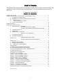
NORTH STAR ENGINEERED PRODUCTS
OPERATION AND SERVICE MANUAL
FOR THE
FP-35
FOOD PROCESSING CENTRIFUGE
TEST & INSPECTION SHEET
SOLD TO _____________________________
MACHINE
_______________ MODEL
_______________ NSEP ORDER #
_______________ SERIAL NUMBER
_______________ DATE
MOTOR & CONTROLS
_______________ INVERTER S/N
_______________ MOTOR VOLTAGE
_______________ CONTROL VOLTAGE
_______________ MOTOR MFG
_______________ INCOMING POWER
_______________ MOTOR S/N
_______________MOTOR HORSEPOWER
_______________ MOTOR RPM
_______________ MOTOR PULLEY SIZE
_______________ MOTOR CODE NO.
_______________ DRIVE BELT
DRIVE UNIT AND BASKET
_______________ UNIT PULLEY SIZE
_______________ BASKET RPM (MAXIMUM)
_______________ BASKET WEIGHT CAPACITY
TESTING RESULTS
_______________ PROCEDURE NUMBER USED
_______________ STARTING AMPS
_______________ RUNNING AMPS
_______________ BRAKING TIME
_______________ INSPECTORS INITIALS
NORTHSTAR ENGINEERED PRODUCTS DIV
GLASSLINE CORPORATION
28905 GLENWOOD ROAD.
PERRYSBURG, OHIO 43561
FORM Z-00860
REV C 6/23/05
2
TEST & INSPECTION SHEET
SOLD TO _____________________________
MACHINE
_______________ MODEL
_______________ NSEP ORDER #
_______________ SERIAL NUMBER
_______________ DATE
MOTOR & CONTROLS
_______________ INVERTER S/N
_______________ MOTOR VOLTAGE
_______________ CONTROL VOLTAGE
_______________ MOTOR MFG
_______________ INCOMING POWER
_______________ MOTOR S/N
_______________MOTOR HORSEPOWER
_______________ MOTOR RPM
_______________ MOTOR PULLEY SIZE
_______________ MOTOR CODE NO.
_______________ DRIVE BELT
DRIVE UNIT AND BASKET
_______________ UNIT PULLEY SIZE
_______________ BASKET RPM (MAXIMUM)
_______________ BASKET WEIGHT CAPACITY
TESTING RESULTS
_______________ PROCEDURE NUMBER USED
_______________ STARTING AMPS
_______________ RUNNING AMPS
_______________ BRAKING TIME
_______________ INSPECTORS INITIALS
NORTHSTAR ENGINEERED PRODUCTS DIV
GLASSLINE CORPORATION
28905 GLENWOOD ROAD.
PERRYSBURG, OHIO 43561
FORM Z-00860
REV C 6/23/05
3
FP-35 CENTRIFUGE TEST RESULTS
S.O. # _______________________
CUSTOMER _____________________
SERIAL # _____________________
1. CYCLE TEST MACHINE 15 TIMES WITH MAXIMUM LOAD OF BASKET CAPACITY,
INCLUSIVE SAFETY EVALUATION. CHECKED BY: ________
2. 5 OF THE 15 TEST CYCLES FILL BASKET WITH WATER AND CHECK FOR SEAM
AND LID LEAKS. CHECKED BY: ________
3. 3 OF THE 15 TEST CYCLES RECORD CYCLE TIME.
___ MIN. & ___ SEC.
___ MIN. & ___ SEC.
___ MIN. & ___ SEC.
4. WELD COSMETICS: CHECKED BY: _______
5. WEIGHT CAPACITY OF BASKET. _________ LB.
6. COMMENTS ON MACHINE AND OPTIONS
_________________________________________________________________
_________________________________________________________________
7. INSPECTOR'S INITIALS ___________
4
FP-35 CENTRIFUGE TEST RESULTS
S.O. # _______________________
CUSTOMER _____________________
SERIAL # _____________________
1. CYCLE TEST MACHINE 15 TIMES WITH MAXIMUM LOAD OF BASKET CAPACITY,
INCLUSIVE SAFETY EVALUATION. CHECKED BY: ________
2. 5 OF THE 15 TEST CYCLES FILL BASKET WITH WATER AND CHECK FOR SEAM
AND LID LEAKS. CHECKED BY: ________
3. 3 OF THE 15 TEST CYCLES RECORD CYCLE TIME.
___ MIN. & ___ SEC.
___ MIN. & ___ SEC.
___ MIN. & ___ SEC.
4. WELD COSMETICS: CHECKED BY: _______
5. WEIGHT CAPACITY OF BASKET. _________ LB.
6. COMMENTS ON MACHINE AND OPTIONS
_________________________________________________________________
_________________________________________________________________
7. INSPECTOR'S INITIALS ___________
5
SCOPE OF MANUAL
This manual is the operation and service manual for model FP-35 food processing centrifuge with
pneumatic lid lock, automatic start and a digital timer. Lid cylinder updated starting with S/N
FP35-130.
TABLE OF CONTENTS
IMPORTANT POINTS .............................................................................................................................7
PREPARATION FOR USE AND INSTALLATION INSTRUCTIONS..................................................8
I. UNPACKING INSTRUCTIONS .........................................................................................8
II. PREPARING YOUR MACHINE FOR INSTALLATION..................................................8
III. INSTALLATION..............................................................................................................8
MOUNTING PRECAUTIONS .....................................................................................9
IV. SAFETY SYSTEM TEST ....................................................................................................10
SPECIFICATIONS ....................................................................................................................................11
OPERATING INSTRUCTIONS ...............................................................................................................12
A. DESCRIPTION OF CONTROLS ........................................................................................12
SETTING THE DIGITAL TIMER...................................................12
SETTING THE INTERNAL PRESSURE REGULATOR...............12
B. LOADING PRODUCT ........................................................................................................12
C. OPERATION........................................................................................................................12
D. OPERATION OF SAFETIES ..............................................................................................13
SEQUENCE OF OPERATION ........................................................14
I. STARTING SEQUENCE.....................................................................................................14
II. STOPPING SEQUENCE .....................................................................................................14
TROUBLE SHOOTING GUIDE
MODEL FP35..............................................................................................................................15
SCHEDULED MAINTENANCE PROGRAM
MODEL FP35..............................................................................................................................16
I. WEEKLY PROCEDURES...................................................................................................16
II. MONTHLY PROCEDURES ...............................................................................................16
III. SEMIANNUAL PROCEDURES .....................................................................................16
SPARE PARTS............................................................................................................................17
INVERTER INITIALIZATION PROCEDURE .........................................................................18
INVERTER PROGRAMMING PROCEDURES........................................................................18
CALCULATING FREQUENCY FOR A DESIRED SPEED.....................................................18
TO ADJUST SPEED ONLY .......................................................................................................18
TO ADJUST ALL PARAMETERS ............................................................................................19
INVERTER FAULT CODES......................................................................................................19
FIGURE 1 - MAIN ASSEMBLY, SHEET 1 ..............................................................................20
FIGURE 2 - MAIN ASSEMBLY, SHEET 2 ..............................................................................21
FIGURE 3 - MAIN ASSEMBLY, SHEET 3 ..............................................................................22
FIGURE 4 - DRIVE UNIT ASSEMBLY....................................................................................23
FIGURE 5 - DRIVE MOTOR ASSEMBLY ...............................................................................24
FIGURE 6 - CONTROL PANEL ASSEMBLY..........................................................................25
FIGURE 7 - ELECTRICAL PANEL ASSEMBLY ....................................................................26
FIGURE 8 - WIRING DIAGRAM..............................................................................................27
FIGURE 9 - SCHEMATIC DIAGRAM......................................................................................28
FIGURE 10 - PNEUMATIC DIAGRAM ...................................................................................29
ADDENDUM FOR EF1 INVERTER OPERATION..................................................................30
6/23/05 Ver. 5.5
6
IMPORTANT POINTS
1.
DO NOT RESTRICT OR REDUCE DRAIN IN ANY WAY.
DO NOT CONNECT THE MACHINE ONTO THE SAME
DRAIN LINE AS OTHER EQUIPMENT. FAILURE TO
ADHERE TO THE FOREGOING MAY RESULT IN A BACK
WASH.
2.
IT IS ESSENTIAL TO MAINTAIN ALL SAFETY SYSTEMS.
FAILURE TO ADHERE TO THE SAFETY MAINTENANCE
STANDARDS MAY VOID THE WARRANTY OF THIS
MACHINE.
7
PREPARATION FOR USE AND INSTALLATION INSTRUCTIONS
MODEL FP35
I.
II.
III.
UNPACKING INSTRUCTIONS:
A.
INSPECT your packaged machine for shipping damage. Look for holes or tears in the packaging
materials and any other outward signs of damage. REPORT ALL DAMAGE TO THE
TRANSPORTATION COMPANY IMMEDIATELY.
B.
Remove packaging from around your machine.
C.
OPEN THE LID of your centrifuge.
D.
REMOVE THE BASKET from your centrifuge.
E.
INSPECT the interior of your machine for any signs of damage.
F.
REINSTALL THE BASKET into your centrifuge.
PREPARING YOUR MACHINE FOR INSTALLATION:
A.
MOVE MACHINE on pallet to desired location.
B.
REMOVE MACHINE FROM PALLET by removing the bolts through the feet of the machine and
sliding the machine off the pallet.
C.
INSPECT the exterior of the machine for shipping damage. Look for dents or scratches in lid, curb
assembly, skirt, or control box. REPORT ALL DAMAGE TO TRUCKING COMPANY
IMMEDIATELY.
INSTALLATION:
A.
MOUNTING:
1.
MARK HOLES on floor by moving the machine into place and marking the hole locations
through the holes in the legs. Make sure to allow adequate space behind the machine for
servicing the rear control panel.
2.
DRILL MOUNTING HOLES. Use 2-1/2" X 1/2" lag bolts into lead anchors in a concrete
floor. (Mounting hardware is not included.)
3.
BOLT machine into place. Do not tighten bolts.
4.
LEVEL MACHINE. Use metal shims under legs if necessary.
5.
TIGHTEN all mounting bolts.
8
MOUNTING PRECAUTIONS
B.
C.
NEVER USE RESILIENT PADS UNDER LEGS.
*
MOUNT MACHINE ON LEVEL SURFACE.
*
CHECK BOLTS PERIODICALLY FOR TIGHTNESS.
INSTALLING THE DRAIN:
1.
The drain should pitch at least one inch per foot for proper flow.
2.
The drain's flow should not be restricted or reduced.
3.
The drain should dump into an open sump or be vented to prevent water backup.
PNEUMATIC CONNECTION:
1.
D.
*
Connect 60 - 80 PSI air to the regulator/filter on the machine.
ELECTRICAL CONNECTION:
1.
INSPECT the data plate on the machine to confirm the required input voltage and amperage.
2.
DISCONNECT BOX: The centrifuge should be connected to its own electrical disconnect box,
which should be remotely mounted. DO NOT mount the disconnect box on or next to the
machine. For proper fusing see SPECIFICATIONS on page 8.
3.
NATIONAL ELECTRICAL CODE: All wiring, motor and circuit disconnecting devices must
be installed in conformance with the National Electrical Code and applicable local codes.
4.
CONNECTION OF CENTRIFUGE:
a.
Wire the free end of the electrical cable into your junction box. The cable will have 2 or 3
power wires and a ground wire. A piece of sealtite flexible conduit is provided with the
machine. Inspect the connection of the power wires into the disconnect box.
b.
Depress the red STOP button.
c.
Turn on incoming power.
d.
Test the operation of your centrifuge.
1. Set the timer to 3 minutes.
2. Open the lid.
3. Pull the STOP button out, and close the lid.
9
IV.
SAFETY SYSTEM TEST:
A.
Make sure that the back panel is securely fastened to the control box.
B.
START THE MACHINE BY CLOSING THE LID
C.
D.
1.
Green light must be lit.
2.
Lid must lock.
PUSH BUTTON TO STOP THE MACHINE:
1.
Machine should stop in 10 - 15 seconds.
2.
Light should go out after machine stops and lid opens.
RE- START MACHINE:
1.
Close lid. If the timer has timed out, the lid must open then close to allow the machine to be
restarted.
2.
Green run light should be on.
3.
The machine should re-start and run through its complete cycle. The machine should stop
within 15 seconds of the end of its cycle.
4.
Green run light should go out after the machine has stopped.
5.
Lid may be opened at the end of the cycle.
6.
The basket should not be spinning when the lid is opened.
IF THE SAFETY SYSTEM IS NOT WORKING PROPERLY, TAKE THE CENTRIFUGE OUT
OF SERVICE IMMEDIATELY.
CONSULT THE FACTORY AT (419) 726-2645 FOR ASSISTANCE WITH CORRECTING ANY
SAFETY ISSUES.
10
SPECIFICATIONS
SPECIFICATIONS
MODEL FP35
BASKET CAPACITY
BASKET HEIGHT
BASKET DIAMETER
BASKET SPEED
TIMER RANGE
DRIVE TYPE
MOTOR SIZE
35 POUNDS
23 INCHES
18 INCHES INSIDE DIA
800 RPM MAXIMUM
0 -60 MINUTES (ADJUSTABLE)
INVERTER DRIVEN MOTOR
1 1/2 H.P.
ELECTRICAL SERVICE
208-230V / 60Hz / 1 or 3 PHASE
10 AMP SERVICE
DIMENSIONS
HEIGHT TO LID TOP
OVERALL HEIGHT
DRAIN HEIGHT
DRAIN SIZE
FLOOR AREA REQUIRED
NET WEIGHT
SHIPPING WEIGHT
40 INCHES
45 INCHES
11.5 INCHES
2 INCH O.D.
26"W x 42"D
550 POUNDS
625 POUNDS
PNEUMATIC REQUIREMENTS
60 - 80 PSI (4 - 5.5 BARS)
11
OPERATING INSTRUCTIONS
A. Description of controls:
1.
RUN LIGHT
Green light which is illuminated whenever the machine is running and the lid is locked.
2.
SPEED SELECTOR SWITCH
The SPEED selector switch is a three position switch which controls the speed of the centrifuge.
The three speeds are programmed into the inverter. These speeds may be changed by adjusting the
parameters in the inverter. The three programmed speeds are: 400 RPM, 600 RPM, and 800 RPM.
3.
STOP SWITCH:
The STOP switch is a maintained push button switch which may be used to stop the centrifuge in
case of excessive vibration or other occurrence that requires immediate stopping of the centrifuge.
It must be pulled out in order to restart the machine.
4.
TIMER:
The TIMER determines the amount of time that the centrifuge runs before it begins to decelerate.
The digital display in the timer will count down to indicate that it is running. After the cycle is
complete, the timer will remain in a timed out condition until the lid is opened.
SETTING THE DIGITAL TIMER
1.
Press the SET button. The display the present setting.
2.
Press the arrow (▲) button beneath the digit to be changed until the correct setting is displayed.
3.
After the correct setting is displayed, press the ENT button to store the new setting. The display will
flash for a few seconds to indicate that the new value has been stored.
SETTING THE INTERNAL PRESSURE REGULATOR
The internal pressure regulator controls the pressure sent to the cylinders to lift the lid. Set it so that the lid just
opens at the end of the drying cycle. Too much pressure will force the lid to open too rapidly, possibly damaging
the machine. The lid may not open automatically if the regulator is set for too little pressure.
B. Loading Product:
1.
Never load basket with more than the dry weight capacity or above the top.
2.
Load evenly for a balanced load. Never allow anything to hang over the top of the basket.
3.
Loads should remain several inches below the inside of the basket top. Do not load above the holes in the
basket.
C. Operation:
1.
The machine is equipped with a timer which has an adjustable range of 0 -60 minutes (longer times may be
programmed by adjusting internal DIP switches). The timer is located on the side of the machine. Locate the
timer and push the SET button to adjust the length of cycle.
2.
Lift the lid and remove the basket from the machine. Load the basket evenly (no higher than the perforated
holes in the basket sides). Place the basket into the machine. Pull out the STOP button (if it is depressed).
Close the lid completely to start the machine.
3.
The green run light will turn on, the lid will lock, and the machine will run for the time set on the timer. Do
not attempt to open the lid while the RUN light is lit.
4.
At the end of the cycle, the machine will automatically stop, then open after the RUN light turns off. After
the basket has been refilled with wet product and placed back into the machine, close the lid to restart the
machine.
D. Operation of Safeties:
12
1.
The lid must be closed before the machine will start. A proximity sensor senses the closure of
the lid. The sensor is located inside the control box. The lid must be firmly closed before the
sensor will allow the machine to operate.
2.
The run light is controlled by the inverter which runs the motor. When the motor is running, a
signal from the inverter keeps the run light illuminated and the lid locked. When the rotation of
the motor stops, the inverter turns the light off and opens the lid.
3.
Failure of any safety switch or overload device will automatically cause the machine to come to
a stop. The failure must be corrected before the machine will restart.
IF ANY OF THESE SAFETIES ARE NOT WORKING CORRECTLY, THE MACHINE
SHOULD BE IMMEDIATELY TAKEN OUT OF SERVICE.
CALL THE
MANUFACTURER AT (419) 726-2645 FOR ASSISTANCE.
13
SEQUENCE OF OPERATION
MODEL FP35
I.
STARTING SEQUENCE:
A.
II.
STARTING THE MACHINE The closing of the lid activates the lid closed proximity switch which
in turn energizes the lid closed relay, CR1. CR1 energizes the START relay, CR2. CR2 energizes
the RUN relay, CR3. CR3 is held on through the lid closed relay, CR1. CR3 also allows power to
be applied to the TIMER, which provides a contact closure to the inverter run terminals if the STOP
button is pulled out and the pressure switch is engaged. The inverter turns the green RUN light on
whenever the machine is running.
STOPPING SEQUENCE:
A.
Elapsed time, per the pre-set timer cycle, expires (or the STOP button is pushed).
B.
The inverter begins to slow the machine at a predetermined rate. After the machine stops
(approximately 10 seconds) the 'motor running' contacts of the inverter will open, releasing CR2.
The green RUN light will turn off and the lid solenoid will release, opening the lid. When the lid
opens, CR1 and CR3 release, resetting the timer.
14
TROUBLE SHOOTING GUIDE
MODEL FP35
Potential correction
Problem and possible cause
1.
Machine fails to start
No power to machine
Main breaker off or internal circuit breaker or fuse
tripped or off.
Lid not completely closed
Close lid - the lid closed proximity sensor must sense a
lid closed position for the machine to start. A light on
the sensor illuminates when the lid is closed.
Defective sensor.
Motor doesn't start
Timer is counting down.
STOP button is depressed.
No air pressure.
Defective timer or corrosion in timer base.
Defective inverter.
Motor doesn't start
Green 'run’ light is off.
Timer display is off.
Defective start relay.
See 'lid not closed' above.
Motor doesn't start
Green 'run’ light is on. (Analog timer)
Timer display is off. (Digital timer)
Defective timer.
Defective ‘run’ relay
Motor starts – machine doesn’t turn
2.
3.
Broken drive belt
Machine keeps running
Incorrect timer setting
Timer has failed
See ‘Setting the digital timer’ under Operating
Instructions.
Defective timer
Excessive vibration
Machine is improperly loaded
Motor mount rubber is worn
Motor hanger cap is loose
Stop the machine and rearrange the load.
Replace motor mount rubbers.
Tighten the caps - The rubbers must be tight.
15
SCHEDULED MAINTENANCE PROGRAM
MODEL FP-35
***********************************************************************
*
Read thoroughly before operating your centrifuge.
*
Your NSEP centrifuge requires scheduled maintenance.
*
Always disconnect power before working on any part of the centrifuge.
*
Do not attempt to load or unload if the basket is spinning.
*
Always instruct end users on all operational and safety procedures prior to their operation of the
centrifuge.
*********************************************************************
I.
WEEKLY / MONTHLY PROCEDURES
A.
II.
After each 40 hours of usage, add approximately 13 grams (6-7 pumps with a typical grease gun) of
grease to the grease fitting located at the top of the drive shaft. The recommended grease is
Chevron SRI No.2 or equivalent.
MONTHLY PROCEDURES
A.
B.
Inspect the drive belt(s).
Inspect and test the SAFETY SYSTEM:
1.
VISUAL INSPECTION:
a.
Verify that the back panel is securely fastened to the control box.
2.
START THE MACHINE:
a.
The lid should be closed before the machine will operate.
b.
The run light should be illuminated and the lid should be locked.
3.
STOP THE MACHINE:
a.
Depress the stop button.
b.
Machine should stop in 10 to 15 seconds.
c.
The machine run light should turn off and the lid should open.
4.
RESTART THE MACHINE:
a.
Pull out the stop button.
b.
Close the lid.
c.
The machine should run a complete cycle and stop within 10 to 15 seconds after the completion of
the cycle.
d.
The machine run light should be on during the entire cycle and should turn off after the motor has
stopped spinning.
e.
The basket should be stopped when the run light turns off and the lid opens.
*********************************************************************
IF THE SAFETY SYSTEM IS NOT WORKING PROPERLY,
IMMEDIATELY REMOVE THE MACHINE FROM SERVICE AND CALL
THE FACTORY AT (419) 726-2645.
*********************************************************************
III.
SEMIANNUAL PROCEDURES
A.
B.
Remove the stainless steel CURB. Inspect motor mounting rubbers. Replace mounting rubbers if
the motor is loose.
Perform weekly and monthly procedures as described above.
16
SPARE PARTS
Some of these parts may vary depending upon the machine control voltage . Make sure
that you verify the input and control voltage before ordering.
QUANTITY
P/N
DESCRIPTION
1
38098
120 VOLT DIGITAL CYCLE TIMER
3
28130
120 VOLT CONTROL RELAY
1
28800
TRANSFORMER (230V-460V OPERATION)
1
37955
REGULATOR (LID OPEN)
2
38123
LID CYLINDER
2
38124
ROD CLEVIS
2
38125
PIVOT BRACKET
1
34010
TRANSFORMER (380V OPERATION)
4
34950
BALL STUDS
1
37949
120 VOLT SOLENOID VALVE
1
215-005
OIL SEAL
2
B-64
V-BELT
1
FP35-066
N. C. CONTACT BLOCK
1
FP35-086
AC INVERTER (230V OPERATION)
1
FP35-087
PROXIMITY SENSOR
1
FP35-088
CIRCUIT BREAKER
1
FP35-101
MOTOR
1
FP35-118
BRAKING RESISTOR (230V OPERATION)
1
FP35-150
DRIVE UNIT BEARING (Double Row}
1
FP35-162
AC INVERTER (380V-460V OPERATION)
1
FP35-163
BRAKING RESISTOR (380V-460V OPERATION)
1
FP35-244
DRIVE UNIT BEARING (Single Row}
1
36040
AIR FILTER MINIATURE F/R UNIT
17
FP-35
INVERTER INITIALIZATION PROCEDURE
Programming Procedures
With the inverter in a stop condition, press and hold the SHIFT key, then press the PROGram key. The PRG
indicator will turn on.
Press the UP/DOWN arrow keys to access the desired parameter. The parameter number will be displayed in the
upper left corner of the digital display.
Press the SHIFT key to allow the Data Code to be changed. PRG will start to blink.
Press the UP/DOWN arrows to select the new Data Code.
Press the ENTER key to store the new Data Code. The display shows STOred for one second.
If accidentally changing the wrong parameter, press the SHIFT button to prevent storing incorrect data.
When finished with each parameter, press the PROGram key to exit the Program mode or the UP/DOWN arrows to
select a new parameter.
To Calculate Frequency for a Desired Speed
The formula to calculate the frequency for a machine with a standard 6.4 inch motor pulley and a 9.4 inch drive pulley
is as follows:
FREQUENCY = DESIRED SPEED x 0.0505
The use of this formula eliminates the need to calculate using pulley sizes or ratios because they are already taken into
consideration.
For example, to calculate the frequency required for a speed of 600 RPM, simply multiply 600 times 0.0505 for a
frequency of 30.30 Hertz.
To Adjust Speed Only
Set the three position speed select switch on the front of the machine to position 2.
Press the UP/DOWN arrows on the inverter to select the new desired frequency for speed 2.
Press the ENTER key to store the new Data Code. The display shows STOred for one second.
With the inverter in a stop condition, press and hold the SHIFT key, then press the PROGram key. The PRG
indicator will turn on.
Press the UP/DOWN arrow keys to access parameter number 33 (Speed number 1). The parameter number will be
displayed in the upper left corner of the digital display.
Press the SHIFT key to allow the Data Code to be changed. PRG will start to blink.
Press the UP/DOWN arrows to select the new frequency for speed 1.
Press the ENTER key to store the new Data Code. The display shows STOred for one second.
Press the UP/DOWN arrow keys to access parameter number 34 (Speed number 3). The parameter number will be
displayed in the upper left corner of the digital display.
Press the SHIFT key to allow the Data Code to be changed. PRG will start to blink.
Press the UP/DOWN arrows to select the new frequency for speed 3.
Press the ENTER key to store the new Data Code. The display shows STOred for one second.
Press the PROGram key to exit the Program mode.
To Adjust all Parameters
Set the three position speed select switch on the front of the machine to position 2.
Press the UP/DOWN arrows for a setting of 30.30. (Speed 2)
Press the ENTER key to store the new Data Code. The display shows STOred for one second.
18
With the inverter in a stop condition, press and hold the SHIFT key, then press the PROGram key. The PRG
indicator will turn on.
Using the above procedures to access the desired parameter, set the following:
Set parameter number 21 to 2. (Input mode)
Set parameter number 32 to 45.5. (Maximum Frequency)
Set parameter number 33 to 20.20. (Speed 1)
Set parameter number 34 to 40.40. (Speed 3)
Set parameter number 42 to 30. (Acceleration time)
Set parameter number 43 to 8. (Deceleration time)
Set parameter number 47 to 4.0. (DC brake time)
Set parameter number 48 to 10. (DC brake voltage %)
Set parameter number 68 to 4. (Trip Restart Number)
Set parameter number 69 to 2.00. (Restart Time Delay)
Set parameter number 75 to 5. (Auxiliary relay output)
Press the PROGram key to exit the Program mode.
INVERTER FAULT CODES
FAULT
CAUSE
REMEDY
F01
Inverter malfunction
Press stop key for longer than 1 second to reset. Consult factory if
problem persists.
F03
Bus current error
Press stop key to reset. Consult factory if problem persists.
F04
Power supply overload
Check for problem on V+ line.
F05
No DC bus voltage
Check power resistor for short. Consult factory if problem persists.
F06
Output short circuit
Check motor wiring. Remove motor wires & recheck.
F07
External fault
Not used
F11
Ground fault
Check motor wiring. Remove motor wires and recheck.
F13
Overvoltage on DC bus
Verify correct line voltage. Increase deceleration ramp time.
F16
Acceleration overcurrent
Mechanical overload on motor. Check motor wiring. Increase
acceleration ramp time.
F17
Deceleration overcurrent
Increase deceleration ramp time.
F18
Running overcurrent
Mechanical overload on motor. (Bad bearing?)
F19
Heat sink over temperature
Check for excessive overload on drive.
19
Figure 1
Main Assembly, Sheet 1
20
Figure 2
Main Assembly Sheet 2
21
Figure 3
Main Assembly, Sheet 3
22
Figure 4
Drive Unit Assembly
ITEM
NUMBER
1
2
3
4
5
6
7
8
9
10
11
12
13
14
16
15
FP35-177
FP35-182
FP35-180
FP35-181
FP35-125
FP35-183
37890
FP35-051
FP35-150
FP35-179
FP35-178
215-005
FP35-244
23680
215-015
FP35-246
DESCRIPTION
DRIVE SHAFT
RETAINING RING (INTERNAL)
DRIVE UNIT MOUNTING PLATE
CAP SCREW, HEX HEAD (1/2-13 x 1-3/4")
LOCK WASHER, 1/2" DIA.
RETAINING RING, EXTERNAL
Q. D. SHEAVE (9" DIA)
Q. D. PULLEY BUSHING (1-1/2" BORE)
BEARING, DOUBLE ROW BALL
BEARING SPACER
BEARING HOUSING
OIL SEAL
BEARING, SINGLE ROW BALL
GREASE FITTING (1/4-28 THREAD)
OIL SEAL
RETAINER SCREW
23
Figure 5
Drive Motor Assembly
ITEM
PART NUMBER
DESCRIPTION
1
2
3
4
5
6
7
8
9
10
11
12
13
FP35-101
FP35-248
FP35-160
FP35-161
FP35-247
FP35-106
FP35-107
FP35-108
FP35-109
FP35-060
FP35-110
FP35-112
FP35-113
DRIVE MOTOR
DRIVE MOTOR PLATE
Q. D. SHEAVE
Q. D. BUSHING (FOR 7/8 DIA SHAFT)
MOTOR HANGER
CAP SCREW, HEX HD.,3/8 - 16 x 7/8" LONG
LOCK WASHER, HELICAL SPRING, 3/8ø
FLAT WASHER 3/8ø
CAP SCREW, HEX HD., 5/16 - 18 x 5/8" LONG
LOCK WASHER, HELICAL SPRING, 5/16ø
FLAT WASHER 5/16ø
HANGER PIVOT PIN
SET SCREW, CUP POINT, 1/4 - 20 x 3/8" LONG
24
Figure 6
Control Panel Assembly
REF NUMBER
1
3
4
5
6
7
8
9
10
11
11
T1
T2
T3
PART NUMBER
DESCRIPTION
FP35-063
FP35-065
FP35-066
FP35-067
FP35-068
FP35-069
FP35-070
FP35-071
FP35-072
24470
38098
FP35-076
FP35-077
FP35-078
GREEN PUSH BUTTON
N.O. CONTACT BLOCK
N.C. CONTACT BLOCK
3 POSITION SELECTOR
2 POSITION SELECTOR
ASSEMBLY CLIP
LAMP HOLDER MODULE
LAMP, INCANDESCENT
STOP BUTTON
ANALOG TIMER
DIGITAL TIMER
NAME PLATE (START)
NAME PLATE (MAN. AUTO)
NAME PLATE (SPEED SELECT)
NOTE: START button and MAN-AUTO switch not installed after 1999. Green light
continues as ‘run’ light. Timer located on side of machine.
25
Figure 7
Typical Electrical Panel Assembly
26
Figure 8
Typical Wiring Diagram – Digital Timer Version
27
Figure 9
Schematic Diagram – Digital Timer Version
28
Figure 10
Pneumatic Diagram
29
MANUAL ADDENDUM
FOR THE
FP-35
FOOD PROCESSING CENTRIFUGE
USING MODEL EF1 INVERTER
30
MANUAL ADDENDUM CONTAINS INFORMATION FOR USE WITH THE WOODS
MODEL EF1 INVERTER
TABLE OF CONTENTS
INVERTER INITIALIZATION PROCEDURE................................................. 32
FIGURE 7 - CONTROL PANEL ASSEMBLY ................................................. 34
FIGURE 8 - WIRING DIAGRAM ..................................................................... 35
FIGURE 9 - SCHEMATIC DIAGRAM ............................................................. 36
6/23/03
31
FP-35 EF1 INVERTER
INITIALIZATION PROCEDURE
Programming Procedures
With the inverter in a stop condition, press and hold the SHIFT key, then press the PROGram
key. The PRG indicator will turn on.
Press the UP/DOWN arrow keys to access the desired parameter. The parameter number will be
displayed in the upper left corner of the digital display.
Press the SHIFT key to allow the Data Code to be changed. PRG will start to blink.
Press the UP/DOWN arrows to select the new Data Code.
Press the ENTER key to store the new Data Code. The display shows STOred for one second.
If accidentally changing the wrong parameter, press the STOP button to prevent storing incorrect
data.
When finished with each parameter, press the PROGram key to exit the Program mode or the
UP/DOWN arrows to select a new parameter.
To Calculate Frequency for a Desired Speed
The formula to calculate the frequency for a machine with a standard 6.4 inch motor pulley and a
9.4 inch drive pulley is as follows:
FREQUENCY = DESIRED SPEED x 0.0505
The use of this formula eliminates the need to calculate using pulley sizes or ratios because they
are already taken into consideration.
For example, to calculate the frequency required for a speed of 600 RPM, simply multiply 600
times 0.0505 for a frequency of 30.30 Hertz.
To Adjust Speed Only
Set the three position speed select switch on the front of the machine to position 2.
Press the UP/DOWN arrows on the inverter to select the new desired frequency for speed 2.
Press the ENTER key to store the new Data Code. The display shows STOred for one second.
With the inverter in a stop condition, press and hold the SHIFT key, then press the PROGram
key. The PRG indicator will turn on.
Press the UP/DOWN arrow keys to access parameter number 303 (Speed number 1). The
parameter number will be displayed in the upper left corner of the digital display.
Press the SHIFT key to allow the Data Code to be changed. PRG will start to blink.
Press the UP/DOWN arrows to select the new frequency for speed 1.
Press the ENTER key to store the new Data Code. The display shows STOred for one second.
Press the UP/DOWN arrow keys to access parameter number 304 (Speed number 3). The
parameter number will be displayed in the upper left corner of the digital display.
Press the SHIFT key to allow the Data Code to be changed. PRG will start to blink.
32
Press the UP/DOWN arrows to select the new frequency for speed 3.
Press the ENTER key to store the new Data Code. The display shows STOred for one second.
Press the PROGram key to exit the Program mode.
To Adjust all Parameters
Set the three position speed select switch on the front of the machine to position 2.
Press the UP/DOWN arrows for a setting of 30.30. (Speed 2 = 600 RPM)
Press the ENTER key to store the new Data Code. The display shows STOred for one second.
With the inverter in a stop condition, press and hold the SHIFT key, then press the PROGram
key. The PRG indicator will turn on.
Using the above procedures to access the desired parameter, set the following:
Set parameter number 201 to 2. (Input mode)
Set parameter number 302 to 45.50. (Maximum Frequency)
Set parameter number 303 to 20.20. (Speed 1 = 400 RPM)
Set parameter number 304 to 40.40. (Speed 3 = 800 RPM)
Set parameter number 42 to 30.00. (Acceleration time)
Set parameter number 403 to 8.00. (Deceleration time)
Set parameter number 407 to 3.00. (DC brake time)
Set parameter number 408 to 15.00%. (DC brake voltage)
Set parameter number 608 to 4. (Trip restart number)
Set parameter number 609 to 2.00. (Restart delay time)
Set parameter number 705 to 5. (Auxiliary relay output)
Set parameter number 801 to 2. (Store parameters)
Press the PROGram key to exit the Program mode.
33
Figure 1
Typical Electrical Panel Assembly
34
Figure 2
Typical Electrical Panel Wiring
35
Figure 3
Electrical Schematic
36
Glassline Corporation
Phone: 419/666-5942
Fax : 419/666-1549
www.glasslinecompanies.com
28905 Glenwood Road, P.O. Box 147
Perrysburg, OH 43552-0147
GENERAL TERMS AND CONDITIONS OF SALE
This agreement sets forth general terms and conditions of sale. The quotation and sales contract may incorporate additional and more specific
commercial and technical requirements of sale. The following general terms and conditions are mutually agreed between BUYER and GLASSLINE
to be a part of the sales and purchase order documents.
1.
A.
B.
C.
D.
E.
F.
G.
H.
I.
J.
2.
DEFINITIONS AND GENERAL TERMS AND CONDITIONS
The term GLASSLINE shall refer to Glassline Corporation and all of its affiliated divisions.
The term EQUIPMENT shall refer to any machine, part, product or service sold by GLASSLINE, including subcontracted/purchased
items/options.
The term BUYER shall refer to the buying company and, where applicable, its subcontractors.
The terms and conditions set forth in this agreement are effective at the receipt of order by BUYER and are subject to change by
GLASSLINE without notice before receipt of order by Buyer.
Quotations are valid for 30 days, unless noted otherwise.
No terms, conditions, understandings, usage of trade, dealings or agreements, purporting to vary, modify, explain or supplement this
agreement shall be binding, unless and until hereinafter made in writing and signed by BUYER and GLASSLINE.
This agreement, and its interpretation, shall be governed by the laws of the State of Ohio. If any provision or term of this agreement is held
to be invalid, void or unenforceable, the remaining provisions and terms of the agreement shall remain in force and effect, and shall in no
way be affected, impaired or invalidated thereby. In all cases, the rights and duties of the parties in a dispute arising out of this transaction
shall be governed by the laws of the State of Ohio.
The delegation or assignment by BUYER of any or all of its duties or rights under this agreement without the prior written consent of
GLASSLINE shall be void.
Any information, suggestions or ideas transmitted by BUYER or GLASSLINE, or any of their respective representatives, in connection
with the performance under this agreement are not to be regarded as secret or submitted in confidence, except as may be otherwise
provided specifically in a document signed by a duly authorized representative of GLASSLINE.
This agreement supersedes all previous agreements, written or verbal, and contains the entire agreement between the parties.
TERMS AND CONDITIONS OF BUYER
Should BUYER have standard terms of acceptance that it wishes to make a part of this agreement, such terms must be provided at the time
a quotation is requested and agreed to in writing by GLASSLINE, so that the costs of compliance to such terms as GLASSLINE may
agree, if any, may be added to the bid. GLASSLINE reserves the right to quote these compliance features separately and above their
standard quotation.
3.
A.
B.
C.
D.
E.
4.
A.
B.
C.
3/9/2006
DELIVERY AND CLAIMS
The quoted shipment schedule is non-binding. The shipment schedule will be set at time of order, and is contingent upon BUYER
supplying a clear scope of supply, all technical information, and any required downpayment. A new delivery date may be required,
depending on any technical or scope changes requested after the order date, or delays in receiving payments according to agreed dates.
GLASSLINE shall not be liable for delays in delivery caused by any reason beyond GLASSLINE's control, including, but not limited to,
force majeure, supplier failure, any interruption of GLASSLINE facilities, or any act of any government, or licensing authority.
Unless otherwise noted in the quotation, all shipments are ex-works GLASSLINE Perrysburg, Ohio plant. BUYER bears all risks of loss or
damage to the EQUIPMENT from the time the EQUIPMENT has been placed at the disposal of Buyer at GLASSLINE, whether shipping
is arranged by BUYER or on behalf of BUYER by GLASSLINE. In any case, shipments shall be made strictly according to Incoterms
2000.
After the EQUIPMENT is placed at the required transfer point for BUYER, GLASSLINE neither assumes responsibility for nor authorizes
any expenses, including electrical work, plumbing, compressed air supply, millwright work, extensions/additions, or materials necessary
for the set up and operation of the EQUIPMENT in BUYER's plant or elsewhere. It remains the BUYER’s responsibility to meet all
federal, state and local codes and regulations.
Claims for shipping damage, concealed or otherwise, are the responsibility of BUYER and should be taken up with the delivering carrier
within the stated time allowed for claims. Claims for shipping shortages will not be allowed, unless reported to GLASSLINE within 10
days of shipment.
TITLE
Title to the EQUIPMENT, thus delivered, shall remain with GLASSLINE; until the full purchase price has been received.
BUYER shall keep the EQUIPMENT fully insured, with GLASSLINE named as loss payee until the purchase price is paid. Neither
BUYER nor GLASSLINE shall assign the applicable insurance contact without prior written consent of the other.
Monthly interest, at the rate of 1-1/2% per month on the total unpaid value of the EQUIPMENT will be charged if delivery is delayed at
BUYER's request for more than thirty (30) days after buy-off, or if final payment is delayed beyond thirty days (30) after shipment.
BUYER shall execute and deliver to GLASSLINE such documents and financial statements as may be necessary to perfect the lien or
security interest of GLASSLINE to protect the unpaid balance of the purchase price.
Page 1 of 2
D.
5.
A.
B.
C.
D.
E.
6.
A.
B.
C.
D.
E.
All tools, materials, software, programs, designs, or any technology created for the purpose of producing the EQUIPMENT are the sole
property of GLASSLINE, unless furnished by BUYER with the order. All intellectual property created by GLASSLINE shall remain
property of GLASSLINE.
WARRANTY
GLASSLINE warrants against defects in material and workmanship. Items manufactured by others but installed in or affixed to
GLASSLINE EQUIPMENT are not warranted by GLASSLINE, but bear only such express warranties, if any, of the manufacturer thereof.
GLASSLINE shall replace or repair at its choosing, (ex-works GLASSLINE Perrysburg, Ohio plant) any defective manufactured parts
without charge to BUYER. The warranty does not apply to any labor charges for removal and/or replacement, or to any part thereof which
has a life, under normal usage, inherently shorter than the warranty period. The warranty will be active for a period of:
1) Machinery: 12 months from date of shipping.
2) Replacement/Repaired parts: 6 months from date of shipping.
Warranty shall be deemed waived by BUYER if:
1) The EQUIPMENT is not properly installed by BUYER, according to GLASSLINE installation instructions.
2) The EQUIPMENT has been subjected to misapplication or misuse, neglect, damaging conditions, or is modified in any way without
written approval by GLASSLINE.
3) The production or use of the EQUIPMENT for which it was not intended, or on products out of specification.
The warranty set forth herein is in lieu of all other warranties, whether express, implied or statutory, including those of merchantability and
fitness of any product for a particular purpose, and of any other obligation or liability on GLASSLINE's part of any kind or nature
whatsoever.
The warranty granted herein is non-transferable, and is granted only to the original BUYER.
No employee, agent or other representative has any authority to waive, alter, vary or add to the terms hereof without prior approval in
writing, signed by an officer of GLASSLINE.
LIMITATION OF LIABILITY
It is expressly understood that GLASSLINE's liability for any damages arising out of or related to this transaction, or for its EQUIPMENT,
whether in contract or in tort, is limited to the repair or replacement of the parts thereof as stipulated in the warranty, and is not to exceed
the contract price in respect to which the claim is made.
BUYER is solely responsible for ensuring the safety of all personnel who may be in close proximity to the EQUIPMENT.
GLASSLINE will not be liable for any other injury, loss, damage or expense, whether direct, incidental or consequential, including but not
limited to labor, loss of use, downtime, loss of material, products income, profit or production, or increased cost of operation, or spoilage of
damage to material, arising in connection with the sale, installation, use of, or inability to use, or the repair or replacement of, or late
delivery of, GLASSLINE EQUIPMENT.
BUYER shall indemnify, defend and hold harmless GLASSLINE and its directors, officers, agents and employees, against any and all
demands, claims, actions, damages, liabilities, costs, expenses (including reasonable attorney fees and expenses) and other losses of any
kind whatsoever, whether based upon theories of contract, tort, negligence, strict liability, warranty, indemnification, contribution, statute
or otherwise, for personal injury or property damage caused by BUYER or by any of its directors, officers, agents, employees or
subcontractors, arising out of or relating to the Equipment Buyer shall give GLASSLINE prompt written notice of any such matters and
the full opportunity to defend itself against them. This indemnity of BUYER shall survive the termination of this agreement.
The remedies and limitations set forth in this agreement are the exclusive remedies for claims based upon any defect in or failure of
EQUIPMENT, whether products or services, whether such claims are presented in contract or in tort (including negligence) and however
and wherever instituted. Upon the expiration of the warranty period, all such liability shall terminate.
7.
ORDER ACCEPTANCE
GLASSLINE reserves the right to refuse any order. An order shall be deemed accepted and a binding contract formed when the initial
payment has been received and the order is acknowledged in writing by GLASSLINE.
8.
CANCELLATION BY BUYER
BUYER may cancel the order for all or any EQUIPMENT by written notice prior to shipment. GLASSLINE will stop work on the order
as soon as possible after receipt of written cancellation. BUYER agrees to pay GLASSLINE for all costs incurred by GLASSLINE and/or
other suppliers attributed to the order, including but not limited to components, work-in-process, labor, burden and overhead. Such
payment will not transfer title to BUYER.
9.
ARBITRATION AGREEMENT
Any controversy or claim arising out of or relating to this agreement, or the breach thereof, shall be settled by arbitration in accordance
with the rules of the American Arbitration Association and the statutes of the State of Ohio. All hearings held in connection with any such
arbitration shall be held in Toledo, Ohio (unless the parties agree otherwise in writing), the award of the arbitrator(s) shall be final and
binding upon the parties, and the judgment upon and the award rendered by the arbitrator(s) may be entered in any court having jurisdiction
thereof.
3/9/2006
Page 2 of 2
TERMS AND CONDITIONS-Controlled Doc 12-22-05 (3).Doc