1
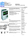
MFS MILLER’S FEEDING SOLUTIONS, INC. MANUFACTURERS OF VIBRATORY FEED SYSTEMS AND PARTS HANDLING EQUIPMENT 10721 75TH STREET NORTH, LARGO, FL 33777-1437 PH: 727-541-5763 – FAX: 727-541-5548 SET UP AND INSTRUCTION MANUAL Miller’s Feeding Solutions (MFS) is committed to the highest quality fabrication of parts handling equipment to meet or exceed customer expectations and production rates. Recognized for innovative technology for even the most difficult of high-rate parts feeding projects, product reliability, sound reduction to meet OSHA standards. MFS is your partner in productivity operations, ensuring optimum efficiency in feeding solutions. 1 MFS MILLER’S FEEDING SOLUTIONS, INC. MANUFACTURERS OF VIBRATORY FEED SYSTEMS AND PARTS HANDLING EQUIPMENT 10721 75TH STREET NORTH, LARGO, FL 33777-1437 PH: 727-541-5763 – FAX: 727-541-5548 TABLE OF CONTENTS Inspection and Setup.........................................................................................Page 3 Intended Use of Machine..................................................................................Page 4 Warnings...........................................................................................................Page 4 Safety................................................................................................................Page 4 Lockout/Tag Out Procedure..............................................................................Page 5 Lockout/Tag Out "Restore"..............................................................................Page 6 Shipping and Transport Instructions.................................................................Page 6 Inserted sections Feeder Controllers Documentation.............................................................Section #1 Main System Layout Drawing....................................................................Section #2 Keyence High Level Sensors......................................................................Section #3 Keyence Bowl Level Sensor.......................................................................Section #4 Final Settings..............................................................................................Section #5 System Run Off Certification.....................................................................Section #6 2 MFS MILLER’S FEEDING SOLUTIONS, INC. MANUFACTURERS OF VIBRATORY FEED SYSTEMS AND PARTS HANDLING EQUIPMENT 10721 75TH STREET NORTH, LARGO, FL 33777-1437 PH: 727-541-5763 – FAX: 727-541-5548 Inspection Un-Crating, and Setup 1) Inspect the crate for any visible damage. If there is any visible damage, TAKE PICTURES OF ALL DAMAGED AREAS AND CONTACT THE CARIER AT ONCE TO REPOST THE DAMAGE AND FILE A CLAIM!! 2) If there is no visible damage, carefully open the crate and inspect the system. If everything appears undamaged proceed with opening and remove system from crate using standard millwright practices. a) Make sure that nothing has worked its way loose in transit and fallen off of the system, check the bottom of the crate. b) Mount or install any components or accessories that may have been disassembled for shipping or shipped separate from the system or may have come loose. 3) The machine should be put into position by means of standard Millwright Practices for moving and final positioning. a) The machine should then be leveled to approximately .005 inches per foot in all directions (level sitting on the table), and sitting on a solid surface with all feet down and locked in place. NOTE: Be sure that all shipping, clamps and materials are removed from the system at this time. 4) A qualified Electrician should connect the machine to the proper electrical supply line. a) See the electrical schematics for power requirements and specifications. b) This must be done using standard electrical practices and local codes for all connections. 5) A qualified plumber or pipe fitter should make the proper air connections following standard plumbing practices and local codes. a) The machine should have a clean and dry air supply of at least 80 psi (unless otherwise specified – see Systems Settings sheet). b) The machine must be plumbed with a large enough pipe for adequate flow to operate efficiently without any pressure drop during normal operation with all air requirements on and in use. 3 MFS MILLER’S FEEDING SOLUTIONS, INC. MANUFACTURERS OF VIBRATORY FEED SYSTEMS AND PARTS HANDLING EQUIPMENT 10721 75TH STREET NORTH, LARGO, FL 33777-1437 PH: 727-541-5763 – FAX: 727-541-5548 Intended Use of Machine This machine is designed and manufactured for use on specific parts. It removes individual parts from a bulk container and presents them oriented for pickup. This machine is not to be used for any other purposes or parts than for which it was intended. Warnings 1. DO NOT operate this machine without all guards and safety equipment in place and 2. 3. 4. 5. 6. 7. operations. Only qualified people should work on and operate this machine. Machine must only be moved by forklift Truck capable of lifting its full weight. Before servicing or repairing, always disconnect Electrical Supply and familiarize yourself with the relevant Lockout/Tag Out procedures and instructions. Never use this machine in any manner, other than it's intended use. This machine must always be connected to earth. As with all Machinery, loose or baggie clothing should not be worn while operating this machine. Safety We strongly recommend using the following Personal Protective Equipment: 1. Ear Protection 2. Safety Glasses 3. Safety Shoes 4 MFS MILLER’S FEEDING SOLUTIONS, INC. MANUFACTURERS OF VIBRATORY FEED SYSTEMS AND PARTS HANDLING EQUIPMENT 10721 75TH STREET NORTH, LARGO, FL 33777-1437 PH: 727-541-5763 – FAX: 727-541-5548 Lockout/Tag Out Procedure This procedure establishes the minimum requirements for the lockout of energy isolating devices whenever maintenance or servicing is done to the MFS Housing Feed equipment. It shall be used to ensure that the machine or equipment is stopped, isolated from all potentially hazardous energy sources and locked out before employees perform any servicing or maintenance where the unexpected energization or start-up of the machine or equipment or release of stored energy could cause injury. This procedure establishes the minimum requirements for the lockout of energy isolating devices whenever maintenance or servicing is done to the MFS Housing Feed equipment. It shall be used to ensure that the machine or equipment is stopped, isolated from all potentially hazardous energy sources and locked out before employees perform any servicing or maintenance where the unexpected energization or start-up of the machine or equipment or release of stored energy could cause injury. All employees are required to comply with the restrictions and limitations imposed upon them during the use of Lockout/Tag Out. The authorized employees are required to perform the lockout in accordance with this procedure. All employees, upon observing a machine or piece of equipment which is locked Out and Tagged Out to perform servicing or maintenance shall not attempt to start, energize, or use that machine or equipment. 1. Notify all affected employees that servicing or maintenance is required on a machine or equipment and that the machine or equipment must be shut down and locked out to perform the servicing or maintenance. 2. The authorized employee shall refer to the company procedure to identify the type and magnitude of the energy that the machine or equipment utilizes, shall understand the hazards of the energy, and shall know the methods to control the energy. 3. If the machine or equipment is operating, shut it down by the normal stopping procedure (depress the stop button, open switch, close valve, etc.). 4. De-activate the energy isolating device(s) so that the machine or equipment is isolated from the energy source(s). 5. Lock out the energy isolating device(s) with assigned individual lock(s) and apply tags to increase visibility and awareness that machine is not energized or activated until locks and tags are removed. 6. Stored or residual energy (such as that in capacitors, springs, elevated machine members, rotating flywheels, hydraulic systems, and air, gas, steam, or water pressure, etc.) must be dissipated or restrained by methods such as grounding, repositioning, blocking, bleeding down, etc. 7. Ensure that the equipment is disconnected from the energy source(s) by first checking that no personnel are exposed, then verify the isolation of the equipment by operating the push button or other normal operating control(s) or by testing to make certain the equipment will not operate. Caution: Return operating control(s) to neutral or "off" position after verifying the isolation of the equipment. The machine or equipment is now locked and tagged out. 5 MFS MILLER’S FEEDING SOLUTIONS, INC. MANUFACTURERS OF VIBRATORY FEED SYSTEMS AND PARTS HANDLING EQUIPMENT 10721 75TH STREET NORTH, LARGO, FL 33777-1437 PH: 727-541-5763 – FAX: 727-541-5548 Lockout/Tag Out Procedure "Restore" 1. Restoring Equipment to Service. When the servicing or maintenance is completed and the machine or equipment is ready to return to normal operating condition, the following steps shall be taken. 2. Check the machine or equipment and the immediate area around the machine to ensure that nonessential items have been removed and that the machine or equipment components are operationally intact. 3. Check the work area to ensure that all employees have been safely positioned or removed from the area. 4. Verify that the controls are in neutral. 5. Remove the lockout devices and reenergize the machine or equipment. Note: The removal of some forms of blocking may require re-energization of the machine before safe removal. 6. Notify affected employees that the servicing or maintenance is completed and the machine or equipment is ready for used. Shipping and Transport Instructions 1. A qualified Electrician should disconnect the machine from the electrical supply line. a. See the electrical schematics for power requirements and specifications. 2. This must be done using standard electrical practices and local codes. 3. The machine should be removed from its position by means of standard Millwright Practices for moving to shipping. 4. Carefully crate system. 5. Make sure that nothing can work its way loose in transit or fall off of the system. 6. Some components or accessories that may have to be shipped separate from the system or mounted separately in the crate with the system. Be sure these items are secure and protected during shipping. 6 REO-USA, Inc. 3250 North Post Road, Suite 132 Indianapolis, IN 46226 Phone (317) 899-1395 Fax (317) 899-1396 www.reo-usa.com [email protected] REOVIB MTS 443 Thyristor Controller for Vibratory Feeders REO 443 Manual_USA 3-Channel Thyristor Controller for Vibratory Feeder A Compact control unit for a typical parts-feeding station comprising Bowl, Linear and Hopper Feeder. - With integral functions for track control, solenoid valve and warning signals - Touch panel with Text/Graphic display for all settings and adjustments - Control Inputs and Outputs - 3 Sensor Inputs for Track and Air Jet Control - 2 x 24 VDC outputs for Air Valve or level sensor - 2 x Status for 'READY' Mains ON and 'ENABLE ON' conditions - 1 x Enable input, 24 VDC or volt-free contacts - 3 x 0..210 V Feeder Outputs Feed Station with Bowl, Inline and Hopper feeder Valve Track Sensor Level Sensor General: The interlocking of channels is predetermined and cannot be altered. The unit enable also enables the linear feeder and all other feeders. If the bowl feeder is inhibited then the hopper feeder also stops. Sensors 1 and 3 can be configured for Track control, Sensor 3 can also be configured for an Air-Jet reject output. Sensor 2 is always used to control the hopper feeder 24V Output 1 switches ON as the bowl feeder starts and switches OFF after a 0...60 secs delay. Should an air-valve be required to operate before the bowl feeder starts then the soft start time should be increased 24 V Output 2 can be used to indicate that components are present on a transfer section at the end of the linear feeder or for controlling an airjet. The output can then be controlled from sensor 3 and ON/OFF time delays can be adjusted in the program under 'AIR JET' Hopper Feeder Bowl Feeder Inline Feeder In the LOGIC menu Sensors 1 and 3 can be configured for track control (MIN/MAX), OR AND or twin track/air operation 1 Overview of Functions: Feeder Feeder Throughput Invert Enable Ramp up time Ramp down time Maximum limit Vibrating Frequency Full/Half Wave Track Control Sensor 1 Invert Switch ON delay Switch OFF delay Empty warning Hopper Control Sensor 3 Invert Switch ON delay Switch OFF delay Empty warning Solenoid Output Output 1: ON with bowl feeder/ delayed OFF Output 2: Using sensor 3 Air jet or 'Present' signal Switch ON delay Switch OFF delay Air Jet / Present Sensor 3 Invert Switch ON delay Switch OFF delay Logic Sensor 1 / Sensor 3 MIN-MAX Vibration levels AND OR Twin Track / Air Technical Data: MTS 443/10A Supply Voltage: Supply Current: Output Voltage per channel: Output Current: Output Current Chan 1: Output Current Chan 2: Output Current Chan 3: 110 / 240 V, 50/60 Hz max 10 A, RMS 0...100 / 0...210 V max. 10 A , RMS max. 8 A, RMS max. 6 A, RMS max. 6 A, RMS Sensor type: Output Status: Control Output 1: Control Output 2: Time out Status - Track: Time out Status - Hopper: Enable Input: PNP, 24 V 24 V, DC, 20 mA 24 V, 200 mA 24 V, 200 mA 24 V, 200 mA 24 V, 200 mA 24 V, 10 mA Operating temp: Storage temp: Recommended Fusing: 0... 45°C -10...80 °C 16 A MTS 443/15A Declaration of Conformity max. 15 A, RMS We declare that this product conforms with the following standards:- max. 15 A, RMS max. 10 A, RMS max. 8 A, RMS max. 6 A, RMS EN 50081-2 and EN 50082-2 in accordance with directive 89/336/EWD REO ELEKTRONIK AG, D-42657 Solingen Total current of ALL control outputs 400 mA Specified Use The units described in this document are electrical goods for use in an industrial environment. They designed for the control of electromagnetic vibratory feeders Settings: Range Linear Feeder: Feeder Speed: Enable Invert: Ramp up time: Ramp down time: Max Output: Half Wave: Bowl Feeder: Feeder Speed: Enable Invert: Ramp up time: Ramp down time: Max Output: Half Wave: Default 0...100 % 0/1 0...60 Sec. 0...60 Sec. 5...100 % 0/1 0% 1 5 Sec. 5 Sec. 90 % 0 0...100 % 0/1 0...60 Sek. 0...60 Sek. 5...100 % 0/1 0% 1 5 Sek. 5 Sek. 90 % 0 Range Hopper Feeder: Feeder Speed: Enable Invert: Ramp up time: Ramp down time: Max Output: AC-Motor for Hopper: Half Wave: Hopper Pulse Feed ON Time: Hopper Pulse Feed OFF Time: Track Control: Invert Enable: Switch ON delay: Switch OFF delay: 2nd Setpoint activate: Time-out activate Time-out time: Default 0...100% 0/1 0...60 Sec. 0...60 Sec. 5...100 % 0/1 0/1 0... 60 Sek. 0... 60 Sek. 0% 1 5 Sec. 5 Sec. 90 % 0 0 0/1 0...60 Sec. 0...60 Sec. 0/1 0/1 30...180 Sec 0 5 Sec. 5 Sec. 0: 0 2 Hopper Feed Control: Enable invert : Switch ON delay: Switch OFF delay: Time-out activate: Time-out time: 24V Output 1: ON Time: 24V Output 2: Switch ON delay: Switch OFF delay: Sensor Logic: MIN-MAX: AND: OR: Twin Track: Any Channel: Range Default 0/1 0...60 Sec. 0...60 Sec. 0/1 30...180 Sec. 0 5 Sec. 5 Sec. 0 30 Sec. 0...60 Sec. 5 Sec. 0...60 Sec. 0...60 Sec. 1 Sec. 1 Sec. 0/1 0/1 0/1 0/1 0/1 0 0 0 0 0 Safety Instructions This description contains the necessary information for the correct application of the product described below. It is intended for use by technically qualified personnel. Qualified personnel are persons who, because of their training, experience and position as well as their knowledge of appropriate standards, regulations, health and safety requirements and working conditions are authorised to be responsible for the safety of the equipment at all times, whilst carrying out their normal duties and are therefore aware of and can report possible hazards (Definition of qualified employees according to IEC 364) ! WARNING ! Hazardous Voltage! Failure to observe can kill, cause serious injury or damage Isolate from mains before installation or dismantling, as well as for fuse changes or post installation modifications Observe the prescribed accident prevention and safety rules for the specific application Before putting into operation check if the rated voltage for the unit conforms with the local supply voltage Emergency stop devices must be provided for all applications, operation of the emergency stop must inhibit any further uncontrolled operation Electrical connections must be covered The earth connection must be checked for correct function after installation and prior to operation Installation ! Are the supply, feeder coil and controller input voltages correct ? Check ! Is the controller adequate for the rated power of the feeder? Is the vibrating frequency set to the correct value for the feeder ? Connect the unit in accordance with the wiring instructions and ensure that the earthing is correct ! ! ! Beware ! Important ! An incorrect feeder frequency setting can cause drive coil (magnet) damage. Ensure that the output frequency of the control unit matches the frequency of the connected coil New units are factory set to the parameters shown in the setting table (Default) If there is any doubt with regard to the settings, the factory defaults can be re-instated from the service menu We reserve the right to make technical changes should we deem them necessary. 3 User Menu: Throughput Power: 1. Hopper Feeder 2. Bowl Feeder 3. Linear Feeder Hopper Feeder: Bowl: Linear Feeder Hopper Sensor: Track Sensor: 1. Invert the enable input (only possible in 'Independent' operating mode) 2. Ramp up time of the feeder after start signal. 3. Ramp down time of the feeder after stop signal 4. Maximum limit of the feeder throughput (Output Voltage) 5. Output for switching a conveyor hopper with 1 ph motor (Output voltage = Supply voltage). 6. Vibration frequency of the feeder Full/Half wave. 7. Switch ON time for pulsed operation of hopper feed. 8. Switch OFF time for pulsed operation of hopper feeder (switch OFF time = 0, corresponds to continuous duty 1. Invert the enable input (only possible in 'Independent' operating mode') 2. Ramp up time of the feeder after start signal. 3. Ramp down time of the feeder after stop signal 4. Maximum limit of the feeder throughput (Output Voltage) 5. Vibration frequency of the feeder Full/Half wave. 6. ON Time for an air valve (24V Output 1) Symbol Bowl Feeder Track Full Hopper Feeder Inhibited, No Enable Linear Feeder Time out exceeded Feeder Throughput 100 1. Invert the enable input (only possible in 'Independent' operating mode' 2. Ramp up time of the feeder after start signal 3. Ramp down time of the feeder after stop signal 4. Maximum limit of the feeder throughput (Output Voltage) 5. Vibration frequency of the feeder Full/Half wave Maximum Limit Ramp up time Ramp down time Switch ON Time Delay 1. Invert the input function 2. Switch-ON time delay for Hopper Feeder 3. Switch-OFF time delay for Hopper Feeder 4. Activate Stop signal for the Hopper Feeder. (Feeder stops after Time-Out has elapsed, only when '1') 5. Time out Delay 1. Invert the input function 2. Switch-ON time delay for Bowl Feeder 3. Switch-OFF time delay for Hopper Feeder 4. Activate operation with two feed levels. Regulates the track feed without time delays by switching between feed rate levels 5. Activate Stop signal for the Hopper Feeder. (Feeder stops after Time-Out has elapsed, only when '1') 6. Time out Delay Air Jet / Present: 1. Invert the input function 2. Switch ON time delay for 24 V Output 2. 3. Switch OFF time delay for 24 V Output 2. Logic: 1. Min-Max Track control using Sensors 1 and Sensor 3. 2. OR-Interlock with Sensor 1 OR Sensor 3 (Use Track switching for interlock output) 3. AND-Interlock with Sensor 1 AND Sensor 3 (Use Track switching for interlock output) 4. Used with twin tracks on a linear feeder with an air-jet ejection of the filled track (Sensor 1 & Sensor 2) Info: Software version, date and configuration Service: 1. Fault Reset 2. Reinstate Factory Settings 3. Select User Settings (4 User Parameters 0...3) 4. Reload selected User Parameter set 5. Choose language 6. Key number for locking & Logic Air Jet (Air Valve) Lock Information Switch OFF Time Delay Service Timer Running Language Invert Switch OFF Impulse Vibrating Frequency Switch ON Impulse Time out Function: The Time Out function can be used to warn that the hopper or bowl feeder have run out of product, but still allowing the feeder to run. If it is required that the feeder stops after the Time-Out delay has elapsed, the 'Time Out ON' must be set to '1' in the sensor menu. When the Time-Out occurs the feeder stops, the corresponding output is energised and a clock symbol is displayed. A Time-Out signal or shutdown can be reset with the green '1' key on the touch panel or by operation of the associated sensor. 4 Settings Run Mode 80.0 % 90.0 % 70.0 % 1 Select Function Group 2 Select Function 3 Set Function 4 Speed Hopper Feeder Speed Hopper: Speed Bowl: 0... 100 % 0... 100 % Hopper Feeder Inverted Enable: I/0 Bowl Feeder Bowl Feeder Inverted Enable: I/0 Linear Feeder Inline Feeder Inverted Enable: I/0 Hopper Ctrl. Further or END Hopper Ctrl. Inverted Input: I/0 Hopper Feeder Soft Start: 0... 60 sec. Bowl Feeder Soft Start: 0... 60 sec. Inline Feeder Soft Start: 0... 60 sec. Hopper Ctrl. On Delay: 0... 60 sec. F1 I F2 0 Start (All Channels) / Reset Time Out Stop (All Channels) Unit reverts to Run Mode If no keys are pressed for approx 5 secs Speed Inline: 0... 100 % Hopper Feeder Soft Stop: Function keys F1 & F2 are not used! 100 0... 60 sec. Bowl Feeder Soft Stop: 100 0... 60 sec. Inline Feeder Soft Stop: 0... 60 sec. Hopper Ctrl. Off Delay: 0... 60 sec. Hopper Feeder Max: Hopper Feeder Motor: 5...100 % I/0 Bowl Feeder Max: Bowl Feeder Half Wave: 5...100 % 100 AC Inline Feeder Max: 5...100 % Hopper Ctrl. Enable Time out: 5...100 % 5 I/0 Inline Feeder Half Wave: I/0 Hopper Ctrl. Time out: 1... 180 sec. Hopper Feeder Half Wave: I/0 Bowl Feeder Air delay: 0... 60 sec. Hopper Feeder Time On: 0... 60 sec. Hopper Feeder Time Off: 0... 60 sec. Track Ctrl. Inverted Input: Track Ctrl. Track Ctrl. On Delay: 0/I Air Jet / Present 0... 60 sec. Air Jet / Present Inverted Input: Logic & Logic Min / Max: 0/I Info Info soft 70700728 Service Service Clear Error / Reset RESET Logic Or: 0/I Info Date: 04.09.2003 Service Factory settings RESTORE Track Ctrl. Enable Time out: 0/I 0/I Track Ctrl. Time out: 1... 180 sec. Air Jet / Present Off Delay: 0... 60 sec. & Track Ctrl. Coarse / Fine: 0... 60 sec. Air Jet / Present On Delay: 0/I & Track Ctrl. Off Delay: 0... 60 sec. & & Logic And: 0/I Logic Air 2 Track: 0/I Info No: nnnn-nnnn Info Config: nnnn-nnnn Service User Index: Service User Params 0... 3 RESTORE 40.0 % 80.0 % 70.0 % 6 & Logic Independent: 0/I Info Config2: nnnn-nnnn Service English English Deutsch Francais Info Config3: nnnn-nnnn Service Code: 0000....FFFF X 4.1 Sensor 1 1 2 3 4 X 4.2 X 4.3 Sensor 3 Sensor 2 1 2 3 4 +24V GND Input +24V X20 5 2 4 1 3 1 4 5 4 5 2 1 3 4 5 4 5 PE 1 1 3 4 PE 2 5 2 1 3 4 Mains Input Bowl Feeder Hopper Feeder Linear Feeder Cable or Socket, Type Han 3+PE Han 3+PE Han 3+PE Han 3+PE 5 0V X 4.1 X 4.2 X 4.3 Sensor 1 Sensor 2 Sensor 3 M 12, 4 pin. M 12, 4 pin. M 12, 4 pin. X 6.1 Enable / Status M 12, 4 pin. 2 X 20 X 21 24 V Output 1 24 V Output 2 M 12, 4 pin. M 12, 4 pin. 3 2 3 X 30 X 31 Time out Track Time out Hopper M 12, 4 pin. M 12, 4 pin. PE 1 3 2 3 Input Power X3 X1 1 2 3 5 4 3 2 +24V 1 2 3 4 0V 2 1 3 X 31 X0 X1 X2 X3 Time out Hopper +24V 1 2 3 4 0V 1 3 2 1 2 +24V 1 2 3 4 0V 1 X30 Time out Track 24V Output 2 +24V 1 2 3 4 GND Input X21 24V Output 1 Connections: +24V Enable GND Status 1 2 3 4 +24V 1 2 3 4 GND Input X6.1 Enable/Status Magnet Magnet A1 1 2 3 A2 PE A1 A2 Brown PE Information for Connectors Blue X2 Gn/Yell Magnet 1 2 3 A1 A2 PE X0 1 2 3 L N PE PE 1 2 3 7 X0 X1, X2, X3 HA-4-M-F / 090218 HA-4-M / 090212 X4.1, X4.2, X4.3 X6.1, X20, X21 X30, X 31 RSV-M-12-4 / 090131 Dimensions:[mm] 200 180 Ø 5,0 REOVIB MTS 443 F2 0 193 I 205 F1 1 5 4 2 1 3 4 1 5 4 2 1 3 4 2 1 3 4 5 5 2 1 3 4 2 1 3 4 5 2 1 3 4 5 5 2 3 2 3 118 F1 5 F2 PE 1 X4.1 X4.2 6,5 X20 X1 Ø 5,0 X4.3 X21 X2 2 X6.1 X30 X3 X31 X0 Ø 5,0 8 PE 1 3 2 PE 1 3 2 3 Service: Key Numbers for Special Settings: By using special 'Key' numbers the end user can be prevented from accessing functions Hide Parameter Menus: 0117 Hide Setpoint: 0137 0117 Hide Parameter Menu: Select "Service" function group Select "Key" function group Using the UP/DOWN cursor keys set 0117 (Characters are in Hex Code 0...F) Next using the RIGHT cursor key set CLOSE to '1’ All menus relating to throughput, info and service are no longer available 0137 Close setpoint: Select "Service" function group. Select "Key" using the UP/DOWN cursor keys set 0137(Characters are in Hex Code 0...F) Next using the RIGHT cursor key set CLOSE to '1' The Throughput menu is no longer accessible The Key numbers are independent of each other and so both keys must be used if all parameters and the setpoint are to be closed Gil Garcia - Vice President [email protected] Phone (317) 899-1395 Fax (317) 899-1396 9 ITEM NO. 1 2 3 4 5 6 7 9 9 10 11 12 13 14 15 16 17 18 19 20 21 PART NUMBER 2678-A 18IN. CCW FEEDER BOWL 18-CCW-BASE-DRIVE FEEDER CONTROLLER 2678-A-S-I-18 INLINE 2678-A DETAIL 1 2678-A DETAIL 2 2678-A DETAIL 3 2203639-G 2678-A DETAIL 4 MFS-0001-M MFS-0004-M FU-77G FS-N11CP OP-73864 1/4-20 X 1 3/8" S.H.C.S. 1/4-28 X 1 1/8" S.H.C.S. 1/4-28 X 1/2" S.H.C.S. 2678-A DETAIL 5 PZ-V32P M3 X 0.5 X 16 S.H.C.S. XLP 7 3 CU FT (8IN. EXT.) DESCRIPTION 18" FEEDER BOWL 18" CCW BASE DRIVE, 115 V REO-MTS-443-15A 230 V 115 V 18" INLINE TRACK BASE RH SIDE GUIDE LH SIDE GUIDE CUSTOMER'S PART TOP CONFINEMANT PE BRACKET POST FOR PIT43TMB5 FIBER SET KEYENCE NEO AMPLIFIER M8 CONNECTOR 2m LONG TRACK BASE TO DRIVE BAR SIDE GUIDE TO TRACK BASE TOP CONFINEMENT TO SIDE GUIDE HOPPER ARM BOWL LEVEL SENSOR M8 QD BOWL LEVEL SENSOR TO HOPPER ARM 3 CU FT HOPPER STOCK SIZE MFS CUSTOM J & J ENG REO USA J & J ENG .75 X 1.75 X 28.00 .48 X .73 X 28.00 .48 X .73 X 28.00 X X 11 GA. X .88 X 28.00 .38 X 1.50 X 2.50 .38 Ø X 2.00 KEYENCE KEYENCE KEYENCE .38 X .75 X 17.00 KEYENCE SERVICE ENG. Material 304 STNLS PURCHASED PURCHASED PURCHASED 304-TRU-BAR 304-TRU-BAR 304-TRU-BAR PLASTIC 304-SHEET 6061-ALUM 6061-ALUM PURCHASED PURCHASED PURCHASED STOCK STOCK STOCK CRS PURCHASED STOCK PURCHASED QTY. 1 1 1 1 1 1 1 1 1 2 2 1 1 2 6 10 6 1 1 2 1 21 3 18 14 SYSTEM OVERVIEW: • • • • • • • • • • • • • • • 12 19 20 PART NAME: 4P HOUSING PART No. 2203639-G PART ORIENTATION: CENTRAL AXIS VERTICAL AND PERPENDICULAR TO TRAVEL, PARTS RIDING ON THE FLAT BASE, APPENDAGE ON SIDE OF PART AWAY FROM BOWL CENTER, OPEN SIDE UP. DISCHARGED HORIZONTALLY. BUILT WITH NO BACK PRESSURE RELIEF. FEED RATE: 50 P.P.M. BOWL ROTATION: COUNTER CLOCKWISE 18" BASIC BOWL SIZE: 28" MAX. O.D. OF BOWL RETURN PAN. BOWL COATING: NONE 27.5" INLINE TRACK. TRACK MATERIAL: 304 STAINLESS STEEL PHOTO CELL HIGH LEVEL SHUT OFF. KEYENCE 3 CU. FT. COLD ROLLER STEEL STD. STORAGE HOPPER. BOWL LEVEL SENSOR. KEYENCE SYSTEM VOLTAGE 115 VAC 60 Hz 1 Ph. REO-MTS-443 CONTROLLER SYSTEM PAINT COLOR: MFS BLUE 1 16 2 11 SAMPLE 10 4 18 PLEASE NOTE: UNLESS OTHERWISE SPECIFIED THIS FEED SYSTEM WILL BE MANUFACTURED TO MILLER'S FEEDING SOLUTIONS, INC. STANDARDS. 13 28 .785 .475 .475 6 17 .875 15 9 9 11 GA. .725 11.000 7 .75 5 1.75 SECTION A-A SCALE 1 : 1 PART COMING AT YOU! 5.00 28.00 0.040 GAP BETWEEN INLINE TRACK AND A BOWL DISCHARGE. 8.00 +2.00 36.38 - .00 A 14.00 miller's feeding solutions, inc. 8.58 10721 75th. Street North Largo, FL 33777-1437 727-541-5763 DATE 12/02/13 CUSTOMER X 4.75 CENTER HOPPER TO BOWL RELEASED DATE BY DRW BY J. Clark TITLE X FILE NAME 2678-A MAIN LAYOUT-SAMPLE Tolerence Unless Otherwise Specified .XXX ± .005 .XX ± .010 .X ± .030 ANGLES ± 1/2° DO NOT SCALE DRAWING SCALE: 1:6 And As Noted MFS JOB NUMBER 2678-a 96M11513 FS-N10 Series Quick Start Quick Start Digital Fiber Sensor Mode/Output *2 Fine sensitivity adjustment FS-N10 Series Up Press the [MODE] button once, then use to select L-on or D-on Down Preset function Instruction Manual Configure easily with a single press when receiving light Setting value Light intensity Power select switch *1 Sensitivity setting Standard ⇔ MEGA (fixed) Press once each for workpiece/no workpiece *1 This is a channel switch on 2-output types. This is not equipped with the 0-line type. *2 Press and hold the [MODE] button to make advanced setting changes. Names of Each Part of the Main Unit and Expansion Unit Fiber lock lever SET button (SET) Read this manual before using the product in order to achieve maximum performance. Keep this manual in a safe place after reading it so that it can be used at any time. Danger Failure to follow these instructions may lead to death or serious injury. Warning Failure to follow these instructions may lead to injury. Caution Failure to follow these instructions may lead to product damage (product malfunction, etc.) Operation status indicators PST indicator Sub screen (Displayed in green) DTM indicator Digital display Note Manual button ( ) Main screen (Displayed in red) Expansion protective cover Expansion connector Provides additional information on proper operation. MODE button (MODE) Preset button (PRESET) This provides useful tips for the feature being described. Cable*2 Tip Power select switch*1 Dust cover See "FS-N10 Series User's Manual" for details on the features of the FS-N10 Series and detailed instructions for configuration. *1 Setting to "M" locks the power mode to MEGA mode. The switch is a channel switch for the two output type. This is not equipped with the 0-line type. *2 On the FS-N1 C , this is an M8 connector rather than a cable. On the FS-N1 EN, this is an e-CON connector. Hints on Correct Use Mounting Unit • This product is just intended to detect the object(s). Do not Warning Mounting on a DIN Rail use this product for the purpose to protect a human body or a part of human body. • This product is not intended for use as explosion-proof product. Do not use this product in a hazardous location and/or potentially explosive atmosphere. • This product uses DC power. Do not apply AC power. The product may explode or burn if an AC voltage is applied. 1 2 • Do not wire the amplifier line along with power lines or high-tension lines, as the sensor may malfunction or be damaged due to noise. • When using a commercially available switching regulator, ground the frame ground terminal 3 Align the claw at the bottom of the main body with the DIN rail, as shown in figure1. While pushing the main body in the direction of the arrow 1, push down in the direction of arrow 2. 2 1 figure1 To dismount the sensor, raise the main body in the direction of the arrow 3 while pushing the main body in the direction of arrow 1. Installation on a Wall (Main Unit Only) and ground terminal. • Do not use the FS Series outdoors, or in a place where extraneous light can enter the light- 1 receiving element directly. • Due to individual dispersion characteristics and the difference in fiber unit models, the maximum sensing distance or displayed value may not be the same on all units. Attach the unit to the optional mounting bracket (OP73880), and secure with two M3 screws as shown in figure2. • If the sensor is used for a long time with the APC function enabled and the LED is imposed with a heavy load, the current consumption of the sensor for light emission will become constant and 'END APC' will be displayed. The sensor can still be used in this case. However, replace the sensor if even small changes in received light intensity should be detected for precise detection. OP-73880 figure2 Connecting Fiber Unit Precautions on Regulations and Standards 1 UL Certificate 2 This product is an UL/C-UL Listed product. • UL File No. E301717 • Category NRKH,NRKH7 • Enclosure Type 1 (Based on UL50) 3 4 Be sure to consider the following specifications when using this product as an UL/C-UL Listed Product. • Use the power supply with Class 2 output defined in NFPA70 (NEC: National Electrical Code). • Power supply/ Control input/ Control output shall be connected to a single Class 2 source only. • Use with the over current protection device which is rated 30V or more and not more than 1A. Included accessories • Instruction Manual 1pc. 1 Open the dust cover in the direction shown by arrow 1. 1 Move the fiber lock lever in the direction shown by arrow 2. Insert a fiber unit into the amplifier as indicated by arrow 3 (approximately 14 mm). Move the fiber lock lever in the direction shown by arrow 4 to secure the fiber. 4 2 3 Fiber insertion sign . Note Other Calibration Methods • If a thin fiber unit is used, an adapter provided with the thin fiber unit will be required. Unless the correct adapter is connected, the thin fiber unit will be loose and not detect targets correctly (the adapter is supplied with the fiber unit). Cable outer dia Adapter φ1.3 Adapter A (OP-26500) φ1.0 Adapter B (OP-26501) Increased Resistance to Dust and Dirt z Appearance Maximum Sensitivity Calibration In the state shown below, press and hold the [SET] button for three seconds or more. Stop pushing when "5'6" flashes. The sensitivity is set slightly higher than the received light intensity. Thrubeam model : with workpiece Workpiece • To connect the coaxial reflective type fiber unit to the amplifier, connect the single-core fiber to the transmitter side, and connect the multiple-core fiber to the receiver side. Single-core fiber Multi-core fiber Press and hold for 3 seconds or more Transmitter Reflective model : without workpiece Receiver Press and hold for 3 seconds or more Connecting Multiple Amplifiers Up to 16 expansion units can be connected to one main unit. However, two output types will be treated as two main units. Warning Note 1 2 Calibrate with a Moving Workpiece Mount on DIN rail and install on metal surface when connecting to multiple amplifiers or mounting main units together. z Fully Automatic Calibration Press and hold the [SET] button with no workpiece in place. While “5'6” is flashing, pass a workpiece through. (Continue pressing the [SET] button while the workpiece passes through.) • When connecting with units other than N-bus (a general term for the KEYENCE wire-saving connection system) compatible sensor amplifiers, including the FS-N10 Series, and the network unit NU Series, consult your nearest KEYENCE dealer. • Turn the power off before connecting multiple expansion units. • Do not touch the expansion connector with your bare hands. Common to Thrubeam and Reflective Models Press and hold until "UGV" flashes Remove the protection covers from the main unit and expansion unit(s). Install the amplifiers on the DIN rail one at a time. While pressing the [SET] button pass through a workpiece 3 4 5 Workpiece Slide the main unit and expansion unit(s) together. Engage the two claws of the expansion unit with the recesses on the main unit side until you hear/ feel a click. Settings complete Position Workpiece z Attach the end units (option: OP-26751) to the DIN rail in the same way as step (2). Positioning Calibration Press the [SET] button with no workpiece. Place the workpiece in the location you wish to position it. Press and hold the [SET] button for at least 3 seconds. Release the button when "5'6" flashes. Secure the amplifiers between the end units. Tighten the screws at the top (two screws x two units) with a Phillips screwdriver to fix the end units. Common to Thrubeam and Reflective Models Press [SET] button once with no workpiece OP-26751 (a set of two) Calibration Method Detecting Even Small Differences z Press and hold [SET] button with workpiece Two-point Calibration Two-point calibration is the basic method of calibration. Press the [SET] button once without the workpiece, and then press it once again with the workpiece. 1 Press and hold until "UGV" flashes Press the [SET] button with no workpiece. [SET] will be displayed on the sub-menu (green display). Workpiece Settings complete Simple, User Friendly Functions 2 Setting the Current Value to 100.0 Press the [SET] button with workpiece. The values will be set and the submenu (green display) will flash. The values will be set to the mid-point between the light intensity when there is no workpiece, and the light intensity when there is a workpiece. With the FS-N10 Series, you can set the current value to 100.0 using simple operations. Standardizing the current value makes it possible for the sensor amplifiers to instantly differentiate reductions in light intensity and is useful in predicting the need for maintenance. Note Workpiece Workpiece If "----" flashes for two seconds on the main screen, the light intensity is too small between conditions when the workpiece is absent and when it is present. These values will be set, but there is the possibility that detection may become unstable. Tip 2 • The various Preset functions listed below cannot be used when the ZeroShift function is enabled. Disable the Zero-Shift function before executing the following functions. • The Preset functions are not suited for transparent workpieces and other cases of detection with low light intensity differences. You can disable various Preset functions by pressing and holding the [PRESET] button. z z Preset Function This function adjusts the current value to "". With light received, press the [PRESET] button. The current value is set to "". Full Auto Preset Function This function automatically differentiates between two conditions (presence/absence of workpiece) and adjusts the current values to "" and "". This is effective for cases when the workpiece is moving at high-speed. Press and hold the [PRESET] button with no workpiece in place. While "#WVQ" is flashing, pass a workpiece through. (Continue pressing the [PRESET] button while the workpiece passes through.) Press [PRESET] button once with no workpiece Common ・ to Thrubeam and Reflective Models Green "PST" lights up Setting is "" Current value is "" Press and hold until "#WVQ" flashes Pressing the [PRESET] button changes the setting and current value as shown below. • Presetting with preset disabled: The setting is changed to "". The setting can be changed via the normal calibration method. • Presetting with preset enabled: Only the current value is changed to "", and the setting is not changed. While pressing the [PRESET] button pass through a workpiece . Handy Uses for the Preset Function Tip z This function is most useful when performing simple detection using a thrubeam model fiber unit (e.g. completely blocked detection, such as when all light axes of the fiber unit are interrupted by opaque workpieces). Workpiece Settings complete Work-Preset Function • Near-maximum values while the [PRESET] button is being pressed and held are This function adjusts the current value to "". After executing the Preset function in a condition in which you would like "" to be displayed, executing this function in a condition in which you would like "" to be displayed, will adjust any two points to "" and "". • The setting value is changed to "" • The green [PST] indicator will light up. Important adjusted to "" and near-minimum values are adjusted to "" . Note The Work-Preset function can be used while the Preset function is in use (when Preset is enabled). Cannot be executed when the Preset function is already being used (when the [PST] indicator is flashing). Press and hold the [PRESET] button to disable the Preset function before executing this function. Set Current Value to "0" Pressing the [PRESET] button and the button at the same time will set the current value at that time to "". Values that have been set to "" with the Preset function cannot be changed. z The Zero Shift Function This function is primarily used with reflective models. Press the [PRESET] button and button at the same time. 100.0 Workpiece 3.0 .0 [PRESET] + Green "PST" lights up • The current value is set to "". • Green "PST" lights up Note z z Disable the Zero Shift Function Press and hold the [PRESET] button to disable the zero shift function. Current value is "" Tip The zero shift and preset function cannot be used together. To use the preset function, you must first disable the zero shift function. Handy Uses for the Zero Shift Function When using this function with reflective models, "" will be displayed when there is a workpiece, and "" will be displayed when there is no workpiece, making it easy to know when the workpiece is present or absent. Additionally, even when with a reflective model, the background has higher light intensity than the workpiece, if you set a condition with low light intensity to "" using the Preset function and then using the Work-Preset function, register a condition with high light intensity as "", the background will display as "" and when the workpiece is present, it will be displayed as "". Tip This function is primarily used to set the current value to "0" on a reflective model fiber unit. When a reflective model is first installed, the light intensity is sometimes not set to "0". If this happens, using the zero shift function to set the value to "0" when there is no workpiece allows for easier understanding of the difference in light intensity. Adjusting the current intensity value when it is too large (when saturated). Maximum Sensitivity Preset Function This function sets conditions that will serve as reference, to "" and adjusts conditions with slightly high light intensity as "". This is useful when you would like to perform detection using the background as a reference with reflective models. In the following conditions, press and hold the [PRESET] button for 3 seconds or more then release your finger when "#WVQ" is flashed. z Use the Saturation Recovery Function Press the [SET] button while pressing the [MODE] button. Thrubeam model : with workpiece Workpiece Press the [SET] button while pressing the [MODE] button. Press and hold for 3 seconds or more After adjusting the light transmission level and light intensity sensitivity, the current values will be adjusted to within the ranges listed in the table that follows. Reflective model : without workpiece Power mode HSP*, FINE, TURBO SUPER ULTRA, MEGA Light intensity setting range 2047 ± 350 4095 ± 500 5000 ± 600 Press and hold for 3 seconds or more *HIGH SPEED • The maximum value for the light intensity while the [PRESET] button is being pressed is • • Note z set to ", and light-intensity that is slightly higher than the maximum value at that time will be adjusted to "". The setting value is "" The green [PST] indicator will light up. Disable Saturation Recovery When the saturation recovery function is enabled, press the [SET] button while pressing the [MODE] button to cancel it. Handy Uses for the Saturation Recovery Function Cannot be executed when the Preset function is already being used (when the [PST] indicator is flashing). Press and hold the [PRESET] button to disable the Preset function before executing this function. Tip 3 This function is useful when the intensity value is saturated after installation. This function corrects the saturation via a simple operation, by automatically calibrating the light transmission level and light intensity gain. Output Switch Initializing the Settings Initialization Method Either light-ON (L-on) mode or dark-ON (D-on) mode can be selected. 1 2 While the current value is displayed, press the [MODE] button once. 1 Use to switch the output (.QP/&QP), then press the [MODE] button again. The output change completes, and the display returns to the current value. Press and hold for 3 seconds or more 2 3 Connecting to External Devices Cable Types FS-N11N/N12N/N13N/N14N z FS-N11P/N12P/N13P/N14P Brown*1 Initial Settings Initial Value Pink*2 current 1 mA or less) Blue FINE Detection mode Std (Normal) Setting value 50 Output switch L-on 0V *1 *1 FS-N11P/N13P only *2 FS-N13P/N14P only Using a Fiber Cutter and Cautions for Use Using a Fiber Cutter FS-N11MN Brown Protection circuit Use the to select "K0K6", then press the [MODE] button. After initialization is complete, the display returns to the current value. Power mode Load Load White (Control output 2)*2 0V *1 *1 FS-N11N/N13N only *2 FS-N13N/N14N only Overcurrent protection circuit to select "456", then press the [MODE] button. Setting (Short-circuit current 2 mA or less) Black (Control output 1) PLC, etc. (Short-circuit Pink*2 Blue *2 Overcurrent protection circuit Sensor main circuit White (Control output 2) Use the PLC, etc. Black (Control output 1) DC3.3V 12 to 24 VDC Brown*1 Load Load Overcurrent protection circuit Sensor main circuit 12 to 24 VDC Sensor main circuit Press and hold the [SET] and [PRESET] buttons simultaneously for three seconds. 1 2 12 to 24 VDC Orange Monitor output (1 to 5V) Black Load (Control output) Blue Device with input impedance 10 kΩ or more Insert the fiber into the cutter hole. Bring down the blade in a single, swift motion to cut the fiber. 2 0V Fiber M8/e-CON Connector Types FS-N11CN/N12CN/N11EN/N12EN 1 Always insert fiber from the side with writing FS-N11CP/N12CP/N13CP/N14CP 12 to 24 VDC PLC, etc. (Short-circuit (Control output 1) 2 1 4 3 Failure to follow the cautions below could reduce the detection range. *3 0V *1 FS-N11CN/N11EN only • The fiber cutter comes with the fiber unit. (Control output 2)*2 current 1 mA or less) *1 (Short-circuit current 2 mA or less) Load DC3.3V Cautions for Using a Fiber Cutter PLC, etc. Load (Control output) M8 connector Pin layout Overcurrent protection circuit Sensor main circuit 12 to 24 VDC *1 Load Overcurrent protection circuit Sensor main circuit *1 Fiber cutter (OP-87098) • When cutting a fiber unit to be attached to the FS-N10 Series, be sure to use a gray fiber cut- 0V *1 ter (OP-87098) • Stopping the blade midway could cause a bad cut plane, reducing the detection range. • Do not use the same hole twice. *1 FS-N11CP/N13CP only *2 FS-N13CP/N14CP only *3 FS-N11CP/N12CP only FS-N11CN/N12CN 2 M8 connector Pin layout 1 4 Function Configuration 3 e-CON connector Pin layout Basic Setting FS-N11EN/N12EN MODE Press and hold M8 connector Cable (Sold Separately) for 3 seconds or more J52 (KPG 6WT$ 5W24 7.64 /')# For FS-N11CN/N11CP/N12CN/N12CP/N13CP/N14CP HIGH SPEED mode MODE OP-73864 (Cable length: 2 m) 4 3 OP-73865 (Cable length: 10 m) 2 1 Pin - Pin and wire color table Connected Wire color pin No. 1 Brown 2 White 3 Blue 4 Black FINE mode TURBO mode SUPER mode ULTRA mode MEGA mode 5'6 5VF 5'6 5'V2 5'6 15'V Error Displays and Corrective Actions Normal sensitivity setting method MODE Error display Cause Solution Check the load and return the current within the rated value. ErC Overcurrent in the control output. ErE Failed to write/load the internal data. Perform initialization (p.4). End APC Loc Large load on the light source. Replace the sensor if highly precise detection is required. The keylock function is ON. For disabling (setting) method, see "FS-N10 Series User's Manual". MODE Consult your nearest KEYENCE office regarding error displays other than the ones listed above. '0& 5V) (W0E 5V) &K52 5V) 5;5 Percentage Calibration*1 Zero-shift calibration MODE Settings complete Go to detection setup mode Go to display setup mode Go to system setup mode Return to normal display *1 You can press the 4 MODE button to set between the range of 2 to 2. Detection Settings System Settings Disable APC Timer OFF Off-delay timer *1 Enable APC 1 On-delay timer * Eco feature off One-shot timer *1 Enable eco feature Normal (light intensity) detection mode Reduce power consumption (response time 4 times slower) DATUM1 mode *2 Standard current value display DATUM2 mode *2 Area detection mode Maximum current value display (4 times hysteresis) Rising Edge Detection Mode Normal operation Falling Edge Detection Mode Twice the number of interference-prevention units as 56& (response time 2 times slower) External input off *6 *1 Disable common key operations External calibration input Enable common key operations Preset input Zero shift input Settings complete Reset input Go to detection setup mode Go to original display setup mode Light transmission OFF input 3 Return to system setup mode Pause mode transition input * Sleep mode transition input Return to normal display Light emission power selection * *1 Main unit only. Analog scaling *5 Two Output *2 4 *7 Light intensity detection mode Settings complete Limit setting output mode Go to display setup mode Go to system setup mode User reset Return to original detection setup mode Auto reset Return to normal display *1 Press the MODE Warning output mode button to set between the range of and (ms). MODE Timer OFF *2 Press the button to set the retouch sensitivity to a range of between .'W and .'W and set the warning output level to a range of between 12 and 2. Off-delay timer *1 MODE Press the button to toggle between Q((/Q0/-''2. Can be set between the range of and . Can be set between the range of and . Can be used only for the types with the external input. Note that these functions can be used via communication when connecting with the network unit NU Series. *7 Only monitor output types (FS-N11MN). *3 *4 *5 *6 On-delay timer *1 One-shot timer *1 Settings complete Display Settings Return to normal display *1 Press the Reverse display Sub-display off Extended display Bar display Excess gain display Light intensity hold display *1 Excess gain hold display *1 L-on / D-on display Enable the saturation of the Preset function *2 Disable the saturation of the Preset function Settings complete Go to system setup mode Go to detection setup mode Return to original display setup mode Return to normal display *2 Press the MODE MODE button to set between the range of and (ms). *2 Only 2 output types (FS-N13N/N13P/N14N/N14P/N13CP/N14CP). Normal display method *1 Press the MODE button to toggle between 5VF/2`2A/D`DA/2AD`/2`DA button to set between the range of 2 and 2. 5 Specifications Type Cable/M8 connector Main unit/expansion unit Standard 1 output Cable Expansion unit Main unit (with output cable) Model NPN PNP Control output Monitor output (1 to 5 V) External input Light source LED Response time FS-N11N FS-N11P 1 output - FS-N12N FS-N12P 1 output - M8 connector*1 Expansion unit Main unit (with output cable) FS-N11CN FS-N11CP 1 output 1 input FS-N12CN FS-N12CP 1 output 1 input e-CON connector*1 Expansion unit Main unit (with output cable) (with output cable) FS-N13CP 2 output - FS-N14CP 2 output - (without output cable) FS-N11MN 1 output 1 output - FS-N10 N/A*2 - 1 to 5 V voltage output; load resistance 10 kΩ or more; repeat precision ± 0.5% of F.S.; 1 ms response time (HIGH SPEED, FINE, TURBO)*4 Monitor output*3 External input input time 2 ms (ON)/20 ms (OFF) or more*5 Up to 16 units can be connected (total of 17 units including the main unit). Note that the two-output type is counted as two units. Protection against reverse power connection, output overcurrent, and output surge Expansion Units Protection circuit Number of interference prevention units Rating Power voltage 0 for HIGH SPEED; 4 for FINE; 8 for TURBO/SUPER/ULTRA/MEGA (When set to double, the number of interference-prevention units will be doubled.) 12 to 24 V DC ± 10% ripple (P-P) 10% or less NPN Normal:900 mW or less (36 mA max. at 24 V, 48 mA max. at 12 V)*6 Eco on mode:800 mW or less (32 mA max. at 24 V, 39 mA max. at 12 V)*6 Eco Full mode:470 mW or less (19 mA max. at 24 V, 23 mA max. at 12 V) PNP Normal : 950 mW or less (39 mA max. at 24 V, 52 mA max. at 12 V)*6 Eco on mode : 850 mW or less (35 mA max. at 24 V, 44 mA max. at 12 V)*6 Eco Full mode : 520 mW or less (21 mA max. at 24 V, 26 mA max. at 12 V) Environme Operating ambient ntal luminance resistance Operating ambient temperature Operating ambient humidity Vibration resistance Shock resistance *1 *2 *3 *4 *5 *6 *7 (with output cable) FS-N11EN FS-N12EN FS-N13N FS-N14N FS-N13P FS-N14P 1 output 1 output 2 output 2 output 1 input 1 input 1 input 1 input Red 4-element LED (wavelength 630 nm) 50 μs (HIGH SPEED)/250 μs (FINE)/500 μs (TURBO)/1 ms (SUPER)/4 ms (ULTRA)/16 ms (MEGA) Light-ON/dark-ON toggle Timer OFF, OFF delay, ON delay, One-shot NPN open collector 24 V; 1 output max: 100 mA or less; 2 output total: 100 mA or less (used stand-alone)/20 mA or less (multiple connections); residual voltage 1 V or less PNP open collector 24 V; 1 output max: 100 mA or less; 2 output total: 100 mA or less (used stand-alone)/20 mA or less (multiple connections); residual voltage 1 V or less Output toggle Timer function Control NPN output output PNP output Case material Case dimensions Weight High functionality 2 output Monitor output 0-line Cable Cable M8 connector*1 Expansion unit Expansion unit Main unit Expansion unit Main unit Main unit Normal : 1050 mW or less (42 mA max. at 24 V, 56 mA max. at 12 V)*6 Eco on mode : 950 mW or less (38 mA max. at 24 V, 47 mA max. at 12 V)*6 - Eco Full mode : 600 mW or less (24 mA max. at 24 V, 29 mA max. at 12 V) Incandescent lamp: 20,000 lx or less; Sunlight: 30,000 lx or less -20 to +55 ° C (no freezing)*7 35 to 85% RH (no condensation) 10 to 55 Hz Compound amplitude 1.5 mm, 2 hours for each of X,Y,Z axis Approx 75g Approx 45g Approx 22g 500 m/s2 3 times for each of X,Y,Z axis Both main unit and expansion unit housing material: Polycarbonate H30.3mm x W9.8mm x L71.8mm Approx 22g Approx 22g Approx 22g Approx 80g Approx 70g Approx 22g Approx 22g Approx 75g Approx 20g Use a cable length of 30 m or less for M8 connector and e-CON connector types. Counted as 1 output when connecting with the network unit NU Series. FS-N11MN only SUPER : 1.2 ms, ULTRA : 1.8ms, MEGA : 4.2 ms Input time is 25 ms (ON)/25 ms (OFF) only when external calibration input is selected. Increases 100 mW (4.0 mA) for High Speed mode One or two more units connected: -20 to +55 ° C; 3 to 10 more units connected: -20 to +50° C; 11 to 16 more units connected: -20 to +45° C. When using 2-outputs, one unit is counted as two units. All temperature regulations are for when the unit is mounted on a DIN rail and installed on metal sheeting. WARRANTIES AND DISCLAIMERS (1) KEYENCE warrants the Products to be free of defects in materials and workmanship for a period of one (1) year from the date of shipment. If any models or samples were shown to Buyer, such models or samples were used merely to illustrate the general type and quality of the Products and not to represent that the Products would necessarily conform to said models or samples. Any Products found to be defective must be shipped to KEYENCE with all shipping costs paid by Buyer or offered to KEYENCE for inspection and examination. Upon examination by KEYENCE, KEYENCE, at its sole option, will refund the purchase price of, or repair or replace at no charge any Products found to be defective. This warranty does not apply to any defects resulting from any action of Buyer, including but not limited to improper installation, improper interfacing, improper repair, unauthorized modification, misapplication and mishandling, such as exposure to excessive current, heat, coldness, moisture, vibration or outdoors air. Components which wear are not warranted. (2) KEYENCE is pleased to offer suggestions on the use of its various Products. They are only suggestions, and it is Buyer's responsibility to ascertain the fitness of the Products for Buyer’s intended use. KEYENCE will not be responsible for any damages that may result from the use of the Products. (3) The Products and any samples ("Products/Samples") supplied to Buyer are not to be used internally in humans, for human transportation, as safety devices or fail-safe systems, unless their written specifications state otherwise. Should any Products/Samples be used in such a manner or misused in any way, KEYENCE assumes no responsibility, and additionally Buyer will indemnify KEYENCE and hold KEYENCE harmless from any liability or damage whatsoever arising out of any misuse of the Products/Samples. (4) OTHER THAN AS STATED HEREIN, THE PRODUCTS/SAMPLES ARE PROVIDED WITH NO OTHER WARRANTIES WHATSOEVER. ALL EXPRESS, IMPLIED, AND STATUTORY WARRANTIES, INCLUDING, WITHOUT LIMITATION, THE WARRANTIES OF MERCHANTABILITY, FITNESS FOR A PARTICULAR PURPOSE, AND NONINFRINGEMENT OF PROPRIETARY RIGHTS, ARE EXPRESSLY DISCLAIMED. IN NO EVENT SHALL KEYENCE AND ITS A FFILIATED ENTITIES BE LIABLE TO ANY PERSON OR ENTITY FOR ANY DIRECT, INDIRECT, INCIDENTAL, PUNITIVE, SPECIAL OR CONSEQUENTIAL DAMAGES (INCLUDING, WITHOUT LIMITATION, ANY DAMAGES RESULTING FROM LOSS OF USE, BUSINESS INTERRUPTION, LOSS OF INFORMATION, LOSS OR INACCURACY OF DATA, LOSS OF PROFITS, LOSS OF SAVINGS, THE COST OF PROCUREMENT OF SUBSTITUTED GOODS, SERVICES OR TECHNOLOGIES, OR FOR ANY MATTER ARISING OUT OF OR IN CONNECTION WITH THE USE OR INABILITY TO USE THE PRODUCTS, EVEN IF KEYENCE OR ONE OF ITS AFFILIATED ENTITIES WAS ADVISED OF A POSSIBLE THIRD PARTY’S CLAIM FOR DAMAGES OR ANY OTHER CLAIM AGAINST BUYER. In some jurisdictions, some of the foregoing warranty disclaimers or damage limitations may not apply. BUYER'S TRANSFER OBLIGATIONS: If the Products/Samples purchased by Buyer are to be resold or delivered to a third party, Buyer must provide such third party with a copy of this document, all specifications, manuals, catalogs, leaflets and written information provided to Buyer pertaining to the Products/Samples. Copyright (c) 2010 KEYENCE CORPORATION. All rights reserved. E 1110-2 6 11513E 1120-1 96M11513 Printed in Japan 96M11228 Sensitivity Adjustment ■ PZ-V (Digital type) ● Detect a moving target (Fully-automatic calibration) Operation Procedure Adjustment Pass a target through the optical axis while 1 pressing the SET button. Self-contained Photoelectric Sensor PZ-V/PZ-M 2 Confirm that “ 3 Release the SET button. The preset value flashes several times before the normal display appears. ” flashes on the monitor. ● To detect a stationary target (Two-point calibration) Operation Instruction Manual 1 Procedure 1 2 Adjustment With no target, press the SET button and release it. “ ” and the current distance flash alternately. With the target in place, press and release the SET button. The preset value flashes several times before the normal display appears. 2 ● To obtain maximum sensitivity (Maximum sensitivity setting) Operation Procedure Adjustment With no target, press the SET button for three 1 seconds or more. ” flashes on the monitor. Confirm that “ Release the SET button. The preset value flashes several times before the normal display appears. 2 3 Note:If the green LED turns off or " - - - " flashes after the calibration, the sensitivity has no allowance. In such a case, adjust the sensor head position, and calibrate again. Read this manual before using the product in order to achieve maximum performance. Keep this manual in a safe place after reading it so that it can be used at any time. ● Fine sensitivity adjustment • When the or button is pressed and released, the numerical value flashes (approx. 2 seconds). This is the preset value. If the or button is pressed again while the preset value flashes, the preset value can be increased or decreased. When the or button is held down for 3 seconds or more, the preset value increases/ decreases continuously. • Precautions on Regulations and Standards ●Other functions ■ UL Certificate Function This product is an UL/C-UL Listed product. • UL File No. E301717 • Category NRKH,NRKH7 • Enclosure Type 1 (Based on UL50) Be sure to consider the following specifications when using this product as an UL/C-UL Listed Product. • Use the power supply with Class 2 output defined in NFPA70 (NEC: National Electrical Code). • Power supply/ Control input/ Control output circuits shall be connected to a single Class 2 source only. • Use with the over current protection device which is rated 24V or more and not more than 2A. Part Names PZ-M PZ-V Operation indicator Operation indicator Sensitivity adjustment trimmer SET button Key-lock Press the and buttons simultaneously for three seconds or more. Lock the operation buttons to avoid the preset value from being accidentally changed. flashes and then the normal display appears. Key-lock Press the and buttons simulcancel taneously for three seconds or more. Unlock the operation buttons flashes and then to allow the preset the normal display value to be appears. changed. Rear side • DARK-ON mode (When LIGHT-ON mode is selected, refer to the description in parentheses.) Procedure Operation Trimmer Indicators PZ-M51(Receiver)/M61/M11/M31/V11/V31 Brown DC12 to 24V Blue 2 Overcurrent protection circuit Photoelectric sensor main circuit 1 0V 4 Brown Pink Thrubeam type PZ-M51(P) (Transmitter) 12 to 24 VDC Output control Load Black Output * 3 Blue 4 2 12 to 24 VDC 0V 3 Blue ( position Procedure 12 to 24 VDC 0V Orange Adjustment With the target in place, turn the trimmer to "Max." With the receiver in place, move the transmitter up/down and right/left. Set the transmitter at the midpoint of the range where the green LED is lit. Secure the transmitter and adjust the receiver position in the same way. Turn the trimmer counterclockwise from Max. until the green LED turns off. Assume the position as Point A. Set the trimmer midway between point A and Max. Confirm sensor operation. • LIGHT-ON mode (When DARK-ON mode is selected, refer to the description in parentheses.) ) 12 to 24 VDC Output DARK-ON mode control LIGHT-ON mode 0V Green Max. Orange Max. Black Output Load Pink A 2 0V Multi-reflective type 1 Max. Orange A Optimal Green PZ-M51P (Receiver)/M61P/M11P/M31P/V11P/V31P Brown Green 1 3 mode *( DARK-ON LIGHT-ON mode Overcurrent protection circuit displayed. ■ PZ-M (Trimmer type) Circled numbers 1 to 4 represent the connector pin numbers. Photoelectric sensor main circuit ON/OFF display Note 1: The distance value indicates a reference value only. It is not an absolute distance. Note 2: If the target approaches the sensor head closer than the specified range, the displayed value may increase. I/O Circuit Photoelectric sensor main circuit OFF Distance display • If the target or background is out of the detectable range, is DOWN button 3 ON • The greater the distance between the target and the sensor head, the larger the displayed value becomes. Digital monitor 1 Display Description ■ Distance display UP button Front side Operation Display Press the and buttons simul- Change the selection display as shown taneously and on the right release them. ) Operation Trimmer Indicators Green 1 A Orange A Orange Green 2 B Optimal 3 position A Green Orange Adjustment With no target, turn the trimmer clockwise until the orange indicator illuminates (turns off) and assume the position as Point A. If the LED does not illuminate (turn off) even with the trimmer at Max., use Max. as Point A. With the target in place, turn the trimmer counterclockwise from Point A until the green LED turns off. Assume the position as Point B. Set the trimmer midway between points A and B. Confirm sensor operation. * The adjustment for the retroreflective type is the same as for the thrubeam type. 1 Specifications Type Model Thrubeam PZ-M51 Detecting distance 2. 10 m Setting distance Light source Sensitivity adjustment Response time Operation mode Indicators 3. Digital monitor — 1.5 ms max. Control output Protective circuit Power supply Current consumption Enclosure rating Ambient light Ambient temperature Relative humidity Vibration Shock Housing material Weight (including 2-m cable) T: 24 mA max. R: 27 mA max. Retroreflective PZ-M61 1. 0.1 to 1.5 m (When R-5 reflector is used) Multi-reflective PZ-M11 1. PZ-M31 1. PZ-M71 1. PZ-V11 1. PZ-V31 1. PZ-V71 1. 5 to 100 mm 5 to 300 mm 20 to 900 mm 5 to 100 mm 5 to 300 mm 20 to 900 mm (10 x 10 cm (10 x 10 cm (30 x 30 cm (10 x 10 cm (10 x 10 cm (30 x 30 cm white paper) white paper) white paper) white paper) white paper) white paper) 30 to 100 mm 40 to 300 mm 150 to 900 mm 30 to 100 mm 40 to 300 mm 150 to 900 mm — (10 x 10 cm (10 x 10 cm (10 x 10 cm (10 x 10 cm (10 x 10 cm (10 x 10 cm white paper) white paper) white paper) white paper) white paper) white paper) Red LED Infrared LED Red LED Infrared LED 1-turn trimmer (230° ) Automatic calibration 1 ms max. (1.2 ms max. with alternate-frequency type, 2 ms max. with M65 only 1.) LIGHT-ON/DARK-ON (selectable by wiring) Output: Orange LED, Stable operation: Green LED — 7-segment 3-digit red LED NPN open collector 24 V; 100 mA or less; residual voltage 1 V or less PNP open collector 24 V; 100 mA or less; residual voltage 1 V or less Reversed polarity protection, Overcurrent protection, Surge absorbe 12 to 24 VDC ±10%, Ripple (P-P) 10% max, Class2 34 mA max. 30 mA max. 38 mA max. 37 mA max. 45 mA max. IP67 Incandescent lamp: 5000 5. lux max., Sunlight: 20000 lux max -20 to +55° C (-4 to 158°F), No freezing 35 to 85%, No condensation 10 to 55 Hz, 1.5 mm double amplitude in X, Y and Z directions, 2 hours respectively 1000 m/s2 in X, Y and Z directions, six times each Glass-fiber reinforced resin T: Approx.50 g R: Approx.55 g Approx. 55 g Approx. 70 g Approx. 55 g Approx. 70 g 1. The alternate-frequency type is indicated by replacing "1" at the end of model name with "5". The models are PZ-M65, M15, M35, M75, V15 V35 and V75. 2. The detecting distance is obtained with the maximum sensitivity. Slit plate+Polarizing filter (Options:A-4) 3. The transmitter of the PZ-M51 features a power indicator only. Slit plate (Slit plate+Polarizing filter) 4. The PNP-output type sensor is suffixed with P after the model name. No slit Slit width (mm) 0.5 1 2 5. 3000 lux max for the PZ-M71P/V71P. 4000 Detecting distance (mm) 500(200) 1000(600) 2000(1300) Target size (mm) Hints On Correct Use 6x6 0.5 x 5 1x5 2x2 WARNING WARRANTY • This product is just intended to detect the object(s). Do not use this product for the purpose to protect a human body or a part of human body. • This product is not intended for use as explosion-proof product. Do not use this product in a hazardous location and/or potentially explosive atmosphere. • • • • • • • • • • • • KEYENCE products are strictly factory-inspected. However, in the event of a failure, contact your nearest KEYENCE office with details of the failure. 1. WARRANTY PERIOD The warranty period shall be for one year from the date that the product has been delivered to the location specified by the purchaser. To extend the cable length, use a cable with at least a 0.3 mm2 nominal cross-section area. Limit the length of cable extension to no more than 100 m. If the amplifier cable is placed together with power lines or high voltage lines in the same conduit, a detection error may occur due to noise interference, or the sensor may be damaged. Isolate the amplifier cable from these lines. When using a commercially available switching regulator, ground the frame ground terminal and ground terminal. Do not use the PZ-V/PZ-M series outdoors or in a place where extraneous light can enter the light-receiving surface directly. When the multi-reflective type is used for the detection of a target with high reflectivity (e.g. mirror-surfaced object), proper detection or distance adjustment may be disabled. In such a case, tilt the sensor head at some angle. During maximum sensitivity setting, the detecting distance may vary due to a difference in characteristics of each unit. Be sure to check that the wiring is properly established. Improper wiring may cause a decrease in sensitivity or overheating and sensor damage. (See “I/O Circuit”.) To mount the sensor, use an M3 screw (coarse thread). Limit the tightening torque to 0.6 N•m or less. To mount PZ-M71/V71, use an M4 screw (coarse thread). Limit the tightening torque to 0.7 N•m or less. To attach the R-5 reflector, use an M3 screw (coarse thread). Limit the tightening torque to 0.3 N•m or less. The displayed value may vary depending on the surrounding environment, such as temperature change or dust. Use a stable power supply. The sensor cannot operate properly if the power supply is unstable at power-on or if the ripple exceeds the specified range. 2. WARRANTY SCOPE (1) If a failure attributable to KEYENCE occurs within the abovementioned warranty period, we will repair the product, free of charge. However, the following cases shall be excluded from the warranty scope. • Any failure resulting from improper conditions, improper environments, improper handling, or improper usage other than described in the instruction manual, the user’s manual, or the specifications specifically arranged between the purchaser and KEYENCE. • Any failure resulting from factors other than a defect of our product, such as the purchaser’s equipment or the design of the purchaser’s software. • Any failure resulting from modifications or repairs carried out by any person other than KEYENCE staff. • Any failure that can certainly be prevented when the expendable part(s) is maintained or replaced correctly as described in the instruction manual, the user’s manual, etc. • Any failure caused by a factor that cannot be foreseen at a scientific/technical level at the time when the product has been shipped from KEYENCE. • Any disaster such as fire, earthquake, and flood, or any other external factor, such as abnormal voltage, for which we are not liable. (2) The warranty scope is limited to the extent set forth in item (1), and KEYENCE assumes no liability for any purchaser’s secondary damage (damage of equipment, loss of opportunities, loss of profits, etc.) or any other damage resulting from a failure of our product. 3. PRODUCT APPLICABILITY KEYENCE products are designed and manufactured as general-purpose products for general industries. Therefore, our products are not intended for the applications below and are not applicable to them. If, however, the purchaser consults with us in advance regarding the employment of our product, understands the specifications, ratings, and performance of the product on their own responsibility, and takes necessary safety measures, the product may be applied. In this case, the warranty scope shall be the same as above. • Facilities where the product may greatly affect human life or property, such as nuclear power plants, aviation, railroads, ships, motor vehicles, or medical equipment • Public utilities such as electricity, gas, or water services • Usage outdoors, under similar conditions or in similar environments Mutual Interference • • • The alternate-frequency type allows mutual interference suppression up to two sensors. The alternate-frequency type is not available for the thrubeam type. To suppress the mutual interference with the thrubeam type or with three or more sensors, contact KEYENCE. Sensor Head Orientation E 1040-1 To detect a moving target, consider orientation of the sensor head according to the direction of the movement. KEYENCE CORPORATION Moving direction Target Correct 1-3-14, Higashi-Nakajima, Higashi-Yodogawa-ku, Osaka, 533-8555, Japan PHONE: +81-6-6379-2211 Target Moving direction Specifications are subject to change without notice. Correct Copyright (c) 2010 KEYENCE CORPORATION. All rights reserved. If you want to mount the sensor head in an orientation other than the above, contact KEYENCE. 11228E 1070-1 96M11228 Printed in Japan 2 A7WW1-MAN-0069 MFS FEED SYSTEM/BOWL SET UP/CHECK OUT JOB No. 2678-A DATE: 1-21-14 BOWL: BOWL ROTATION: CCW BOWL SIZE: 18” BOWL O.D. 28” COILS: 2 VOLTAGE: 120V BOWL FREQUENCY: Hz. 60 Hz. 120 Hz. X BOWL AMPLITUDE: 64 COIL GAP: BACK PRESSURE: MFS REFERENCE JOB No. BOWL SPRINGS: #1 4(1/4”) #2 4 (1/4”) #3 4 (1/4”) #4 4 ( 1/4”) #5 #6 #7 #8 #1 IS SPRING BANK CLOSEST TO THE DISCHARGE, FOLLOW BOWL ROTATION AROUND. DISCHARGE HEIGHT: 13.5 DISCHARGE LENGTH: 5” CENTERLINE: 11” PAN WIDTH: 4.5” PAN WALL HEIGHT: 3.0” ORIENTING ANGLE: 45° ANGLE WIDTH: 2.25” COATING TYPE /COLOR RAL7035 QUICK DUMP: NO COUNTER WEIGHT: YES PART PROBLEMS: AVERAGE RATE COUNTS: 1. 2. 3. 4. 5. 6. 7. 8. 9. 10. REQUIRED RATE: 50 PPM INLINE TRACK: TRACK LENGTH: 28” TRACK MATERIAL: T.S. STNLS. X VOLTAGE: 120V INLINE FREQUENCY: Hz. 60 Hz. X INLINE SPRINGS: #1 2 TK #2 1 TK 1TN #3 #4 #1 IS THE REAR SPRING BANK CLOSEST TO THE DISCHARGE. GRAVITY TRACK: TRACK LENGTH: TRACK ANGLE: TRACK MATERIAL: T.S. CANTED ANGLE: HOPPER: P.E. ANGLE: 90° ON DELAY: SENSOR MODEL: KEYENCE PZV-32P SHUT OFF: P.E. ANGLE: 45° SENSOR MODEL: 7 OFF DELAY: .1 CUSTOMER SUPPLIED: ON DELAY: 1.0 OFF DELAY: FU-77G WITH FS-N11CP AMPLIFIER TRACK GAP: DISCHARGE TO TRACK: .040 FLOWMETER SETTINGS AT 1. 16. 9. 2. 17. CHECKED OUT BY: 10. 3. 18. SCOTT MILLER L.P. INSIDE OF BUCKET PAINTED: 120 Hz. HOPPER AMPLITUDE: 73 1 #4 1 L.O. D.O. PNP NPN 3.5 L.O. X D.O. CUSTOMER SUPPLIED: PNP NPN 4. 19. X TRACK TO NEST/ESCAPMENT: P.S.I. PRESSURE: 11. CONFINEMENT MAT'LL: TRACK AMPLITUDE: 70 #6 STNLS. PLASTIC COATING: "L" TRACK HORIZONTAL DISCHARGE LENGTH: HOPPER SIZE: 3 CUBE HOPPER TYPE: S.F. STD. X HOPPER MATERIAL: STNLS. X CRS. HOPPER LINING: VOLTAGE: 120V HOPPER FREQUENCY: Hz. 60 Hz. X HOPPER SPRINGS: #1 4 #2 5 #3 BOWL LEVEL: PLASTIC: 120 Hz. #5 12. 5. 20. 13. CLOCK No. 6. 004 . 14. 7. SUPERVISOR: 15. 8. System run off certification I Certify, this Miller's Feeding System Inc. feed system has been tested and meets the standard MFS run off criteria as follows: This system has been set up and run for a minimum of (1) hour or, the customers required run time, with an escapement, shuttle, or other escapement mechanism to simulate as closely as possible, the actual stop and start running conditions and feed rate as specified by the customer. This system has run issue free and jam free for a minimum of (1) hour with the exception of a damaged or defective part. Every effort has been made to cycle and operate this system as a complete system, with a full hopper (*) with the parts level in the bowl automatically metered, fed through the feeder bowl, through the track and escaped back into bulk. All sensors have been set, tested and verified to function as designed. All control and air settings have been recorded. All mechanical and electrical drawings as well as solid models have been updated. All documentation from purchased items is included in the documentation package. Instruction manual and documentation package has been printed, saved electronically by the MFS job number. The system has been photographed and a video has been recorded. Signed Date Notes: (*) Customer did not supply an adequate quantity of parts to completely fill the hopper and system to normal full operating conditions.