1
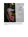
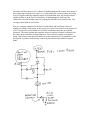
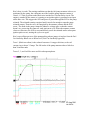
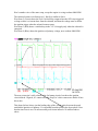
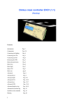
Here is a fairly comprehensive description of the 1983 V4 Magna FUEL CUT-OUT
RELAY, including almost everything I know about this little demon. There’s also some
stuff in here about the ignition system. I’m presenting this information as an aid to
anyone else that may be trying to figure out a problem in this part of their own bike.
These are my observations and do not necessarily represent what you will observe for
yourself. Please don’t cut and paste any portion of this document, rather use this
document in it’s entirety for what it’s worth (free) and at your own risk. That disclaimer
aside, here’s a little history of how this document came to be.
I bought my V45 Magna in March of 1983. I rode a lot that spring and summer, even into
the fall until the weather was too cold around the Chicago area. No problems, the bike
was perfect! In the spring of 1984, this little demon showed up. The bike was impossible
to start after sitting all winter. Eventually, I figured out that there wasn’t any fuel in the
carburetor bowls. And, the fuel pump wasn’t pumping, so I jumped battery to the pump,
listened while it filled the bowls and then stopped pulsing. I put the plug back in place for
normal connections to the pump and the engine started right up. Weird, I thought to
myself, but throughout the summer everything was fine, so I forgot about it until the
spring of 1985. Same problem! What’s up with Honda?? I’m thinking. They wouldn’t
have purposely made this thing so you have to drive it every day would they?? Well, they
sort-of did.
To make matters worse, the low speed jet is so small in each carburetor that it gums up
easily if left sitting too long with old fuel to evaporate. After a few years, there were two
problems, no fuel in the bowls after parked, and hard starting / lack of idle due to the low
speed jets being clogged.
After removing the carburetor assembly the first time, I realized that I was not the little
Japanese girl who had built this thing the first time, my hands are just too big! And, I did
it that first time without removing the radiator, which I have since learned is a real big
help. Cleaning the low speed jet is easy with an acetone soak and some really small wire,
like you would find in a frayed lamp cord. You just need to be really careful not to ream
out the jet hole size.
So, back to the original intent of this story. I traced the wiring to the fuel pump in the
schematic and had some problems because I believed the schematic from the Honda
service manual to be correct (foolish me, more later). Unable to make sense out of it, I
took the brute force approach and intervened at the inputs to the fuel pump. I added a
double pole, double throw switch rated for 15 amps in series with the two fuel pump
wires, so that the common contacts were connected to the fuel pump. One set of switched
contacts were connected to the original circuit so that when the switch was in that
position, the wiring was as originally manufactured. The other set of contacts went
directly to ground and battery through a new inline fuse. And, I used a center off switch
so that in this “OFF” position, I could run the engine to drain the carburetors. This proved
useful because it didn’t leave any fuel in the low speed jets to gum up over the winter. I
still opened the drains to really get rid of the last few drops, but having the engine suck
the last bit out of the jets is also useful.
“The Fuel Cut-Out Relay”
Since I recently brought this 1983 V45 Magna out of storage, and joined Sabmag, I’ve
seen lots of interest in this little “relay”. As some of you already know, it’s not really a
relay. It’s an electronic circuit that senses the presence of pulses between one of the spark
units and it’s associated ignition coil. If these pulses are present, this circuit energizes the
fuel pump.
The fuel pump is a solenoid operated diaphragm with inlet and outlet one way valves.
When there is no back pressure on the pump (empty carburetor bowls), the solenoid pulls
the diaphragm in, drawing fuel from the inlet check valve, and also opening a contact so
that the solenoid circuit is then de-energized. Then, a spring pushes the solenoid armature
and the diaphragm back to the original position, discharging fuel through the outlet valve.
The contact closes. This cycle repeats until the carburetor bowls are filled, assuming the
+12 volt power remains. But, when you are trying to start the engine after things have
been stored for a while, two things work against you. The engine won’t start without fuel
and it’s probably spring, cold weather, so you need extra fuel for the choke circuits, and
the battery is probably weak because you forgot to store it properly. You guys already
know all this, but I hope the electrical / mechanical description of the pump helped some
of you understand it a little better.
Back to the Fuel Cut-Out Relay. This circuit consists of a Silicon Controlled Rectifier
(SCR), which acts like a switch. This SCR is in series with +12 Volts and the fuel pump
solenoid circuit. If the SCR is triggered, it passes +12 Volt power to the fuel pump
solenoid and continues to pass this current until the fuel pump contact opens. Then, the
SCR resets and no more power is passed until the SCR is triggered again. That’s just how
SCRs work. A pulse from the ignition coil generates the SCR trigger signal, so as long as
the engine is running, the SCR gets triggered and the pump gets power. The original
problem that led me to this circuit is that when the carburetors are dry, the pump can’t
prime the bowls fast enough to get the engine to start with a weak battery and without
lots and lots and lots more cranking.
In my 1983 V45 Magna, the Fuel Cut-Out Relay is located under the fuel pump, behind
the battery, and to the left and behind the fuel cut-off valve. It’s a black box about 1 inch
by 1 inch by 2 and a half inches with a white connector at one end connecting three
wires. I have to remove the right fuel pump mounting bolt so I can move the fuel shut off
valve out of the way to get to the Fuel Cut-Off Relay. Yours may be different.
The original Honda service manual schematic is incorrect in the way it shows the wires to
this Fuel Cut-Out relay, The Blue and Black wire positions are swapped in the schematic
from how these are really built. My schematic is labeled 0030Z-MB1-6700 in the lower
right corner.
Fuel Pump
BATTERY
(This big white
thing)
Fuel Shut
Off Valve
Fuel Cut-Out
Relay
To get the Fuel Cut-Out Relay out of there, I had to remove the left side fuel pump
mounting bolt, which also holds the Fuel Shut Off valve mounting bracket. Then I
dropped the bracket down and left the bolt in place. Then I could pull out the Fuel CutOff relay. See below:
Fuel Pump
Bolt Removed
Shut Off Valve &
Bracket
Fuel Cut-Out Relay
Rear Tire
BATTERY
Note that from this view, the wires are (Left to Right) Blue, Black, White. (Ignition, +12
Volts, Output)
Circuit details:
The fuel pump solenoid measures about 2.1 ohms on my 1983 V45 Magna. It takes a
reasonably good VOM to measure this, but I can do this test with a meter that’s on sale at
Harbor Freight for $2.99 from time to time. You just need to measure the difference
between the lead resistance of the meter and the lead resistance plus the pump. A shorted
pump solenoid or wiring harness will blow up the SCR in the Fuel Cut-Out Relay circuit.
And, an open contact or solenoid won’t ever pulse. If you are having problems with fuel
delivery, start by putting a jumper between the black and white wires on this Fuel CutOut relay connector and then turning on the ignition key. The pump should pulse if it is
OK and it will blow the fuse if it is shorted. If nothing happens, the contact in the pump is
bad or the pump solenoid coil is open. So, if it blows the fuse, or does nothing, the pump
is bad. If it pulses until the carburetor bowls are full and then stops, the pump is normal
and the problem is in the Fuel Cut-Out Relay. If nothing happens, make sure the
carburetors aren’t full and the pump isn’t pulsing because there is no need for fuel. You
can open a bowl drain to test for this.
Here is a complete schematic for the Fuel Cut-Out Relay and Fuel Pump. I haven’t
actually seen inside a fuel pump, so this part is just a guess. Pete sent me some pictures of
a Fuel Cut-Out relay circuit board so I traced the connections and came up with this
schematic. The actual resistor and capacitor values are subject to further verification, but
the circuit shown should be accurate otherwise. Since I haven’t actually seen inside a
pump, I don’t know much about the diode across the solenoid, but I’m confident it could
be replaced if you have inadvertently connected power backwards and blown up this
diode.
Here’s how it works: The starting conditions are that the fuel pump armature is down, as
positioned by the spring, the carburetors need fuel, and the pump armature contact is
closed. +12 Volts is present at the Black wire into the Fuel Cut-Out Relay circuit. The
engine is cranked by the starter or is running so an ignition pulse is generated as an input
on the blue wire. This triggers the SCR and power is passed through the SCR to the pump
solenoid. The solenoid remains energized until it travels far enough to open the pump
solenoid contact. Then the coil is de-energized by the armature contact and the SCR
resets. The diode in the pump clamps the inductive voltage spike so that the contact
doesn’t arc, preserving the contact to work again next cycle. When the armature contact
closes at a later time, the SCR is reset and doesn’t power the solenoid until a subsequent
ignition pulse occurs, starting the cycle over again.
Here’s an oscilloscope trace of the pump pulsing when a jumper is in place from the Fuel
Cut-Out Relay Black wire to White wire. (Fuel Cut-Out Relay bypassed)
Trace 1 (Black waveform) is the solenoid current at 1 Amp per division, so the coil
current rises to about 3.2 amps. The full stroke of the pump armature takes a little less
than 30 milliseconds.
Traces 2, 3, and 4 will be more useful in subsequent photos.
This is an oscilloscope trace showing the engine idling (about 1200 RPM).
Waveform 1 (Black) is the pump solenoid current at 1 Amp per division.
Waveform 2 (Green) is the pump solenoid voltage as supplied by the Fuel Cut-Out Relay
Waveform 3 (Red) is the +12 Volt power to the circuits
Waveform 4 (Blue) is the Ignition input on the blue wire.
The solenoid current waveform is pretty similar to the previous picture, except it’s only
conducting for about 22 milliseconds, because the voltage is higher from the battery
being under charge, so the armature moves faster.
You can see the voltage drop across the SCR as it carries this current.
The voltage rise to +12 Volts on waveform 2 (Fuel Cut-Out Relay OUTPUT) is the result
of the SCR being triggered ON by the ignition coil input pulse (waveform 4, blue).
Subsequent ignition cycles try to fire the SCR but the solenoid contact is open so there
isn’t any current flow and the SCR resets when the trigger signal goes away.
Here’s another view of the same setup, except the engine is reving to about 4000 RPM.
The solenoid current waveform (trace 1, black) is similar to above.
Waveform 2 (Green) shows the Fuel Cut-Out Relay output where the SCR stays triggered
as long as there is a current draw from the solenoid, and then the voltage starts to follow
the ignition trigger when the solenoid contact opens.
Waveform 3 (Red) shows a similar drop in the +12 Volt supply only when the solenoid is
energized.
Waveform 4 (Blue) shows the ignition coil primary voltage, now at about 4000 RPM.
The next picture isn’t really related to the fuel pump circuits, but shows the ignition
circuit instead. I figured, it’s connected to the scope, let’s show some more details of how
this works.
This photo (below) shows just the leading edge of the voltage pulse between the spark
unit and the ignition coil primary. It’s expanded from this point in the above photo. Note
that the time-base is now 10 microseconds per division instead of 10 milliseconds as
above.
The ignition coil primary voltage is developed across the primary winding. One end of
this winding is at +12 Volts and the other end of this winding is connected to the
collector of a transistor with it’s emitter grounded. When this transistor is on, current
builds up in the primary circuit, building up an associated magnetic field. When the
transistor turns off, the magnetic field collapses, creating a large voltage spike, which in
turn fires the spark plugs for those two cylinders. This magnetic field collapsing also
generates a fairly high voltage on the primary circuit. As you can see, this reaches 428
volts peak. This is the voltage on the primary winding. If multiplied by the turns ratio of
the ignition coil, you could determine the secondary voltage needed to fire both spark
plugs which are in series. Changing the plug gap, fuel/air ratio, engine load, altitude, etc.
will change the spark voltage, so this is just a single observation of my setup today. Your
similar measurement would most certainly be somewhat different. But the general
waveform shape and timing should be consistent.
It’s this large positive going pulse that triggers the SCR to energize the fuel pump
solenoid any time there is a fuel demand.
Conclusion: That’s pretty much what I know about this topic, I hope it’s been worth the
read.