1
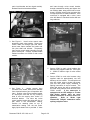
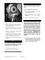
INSTRUCTIONS
Kit Number RJ10011-00
2003 SOFTAIL™ CRUISE CONTROL KIT
GENERAL
This cruise control kit is designed for installation
on 2003 Softail Model Motorcycles. This kit
requires associated model dependent idle cable.
If motorcycle is carburetor equipped, a cruise
control carburetor conversion kit will also be
required. See attached service parts list for kit
contents.
WARNING
Failure to correctly install this kit may adversly
affect the function of your motorcycle. If you
are unsure of your capabilites to correctly
install this kit, or if you are lacking any of the
proper facilities, manuals, or tools you must
have this kit installed by a qualified service
technician. IMPROPER INSTALLATION
AND VEHICLE REASSEMBLY MAY
RESULT IN PROPERTY LOSS, BODILY
INJURY OR DEATH!
WARNING
It is imperative that the kill switch (on the right
hand control) operates properly.
After
installation, and before each vehicle operation,
the kill switch must be tested. In the event the
kill switch does not function correctly, do not
operate the vehicle until proper operation has
been restored. Never under any circumstance
remove right hand from controls. In the event
the cruise control or vehicle malfunctions,
immediately stop the engine with the kill
switch. Always use kill switch to shut off
motorcycle, so that you’re are familiar with it’s
position and operation. IMPROPER KILL
SWITCH OPERATION MAY RESULT IN
PROPERTY LOSS, BODILY INJURY OR
DEATH!
Document P/N: DL10711-00, rev 1.7
Service Manual Required
This instruction sheet refers the installer to the
appropriate Softail service manual for many
procedures. Therefore, you must not attempt to
install this kit without having a copy of the Softail
service manual applicable to your vehicle.
NOTE
If you do not have the correct service manual for
your motorcycle, please contact your HarleyDavidson dealer to obtain one.
Shop Supplies Required
• Liquid Thread Lock
• Materials for splicing wires (refer to
service manual for proper materials)
Specialty Tools Required
DO NOT ATTEMPT CRUISE CONTROL
INSTALLATION WITHOUT PROPER TOOLS
• Tools for splicing wires (refer to service
manual for proper tools)
• As per service manual, tools to remove
and install the following: fuel tank, rear
wheel, air cleaner, hand controls, battery,
instrument panel, rear inner fender, and
seat.
INSTALLATION
1. Remove seat, battery, rear wheel, fuse cover,
instrument panel, air cleaner, fuel tank and
rear inner fender following instructions in
applicable service manual.
2. See Figure 1. Remove bolts in fuse block
bracket. Move fuse block bracket forward on
right side of motorcycle.
Feed 10-place
female Packard connector of the cruise
control wire harness (CCWH) down through
hole beside main wire harness to the main
circuit breaker and the turn signal module.
Align top of wire conduit on CCWH to top of
wire conduit on main harness (routed to the
Page 1 of 6
main circuit breaker and turn signal module).
Reinstall fuse block bracket and bolts.
and insert through cruise control bracket,
through transmission casting and tighten into
nut retaining plate, being careful not to crossthread. Reinsert security siren connector into
its original position on electrical bracket. If the
motorcycle is equipped with a siren, invert
siren and fasten to electrical bracket with two
long cable ties.
Figure 1. Fuse Block Bracket
3. See Figure 2. Uncoil cruise control cable
attached to main cruise module. Feed cruise
control cable out through right side frame,
above lower frame member and under rear
fork pivot shaft and exhaust. Temporarily
leave cruise control cable protruding out right
side of motorcycle. Connect 10-place female
Packard connector on CCWH to main cruise
module.
Figure 3. Cruise Control Module Installed
5. Secure CCWH to main circuit breaker wire
harness using supplied cable ties. See Figure
3 – CCWH is visible to right of cruise control
module.
Figure 2. Main Cruise Module
4. See Figure 3.
Unplug security siren
connector from holder, and remove harness
from electrical bracket (you will reposition this
later). Position cruise control module bracket
on motorcycle such that the top mounting
slots fit over the security siren “hooks” on
electrical bracket.
The lower two cruise
control module bracket bolt holes will line up
with holes in the transmission casting.
Position nut retaining plate on top of
transmission casting over the two holes.
Apply liquid thread lock to provided ¼” bolts
Document P/N: DL10711-00, rev 1.7
6. Secure CCWH to main wire harness using
supplied cable tie approximately one inch
below top of wire conduit. Trim and splice red
wire with yellow stripe to brake light power
(red wire with yellow stripe) according to
splicing instructions in service manual. The
brake light power wire will be exposed from
the main wiring harness near the end of the
CCWH conduit.
If the motorcycle is
equipped with an LED taillight or a brake
light flasher module, there are some
special instructions to ensure correct cooperation.
Refer to “Brake Light
Flasher/LED Taillight” addendum before
splicing red/yellow wires.
Page 2 of 6
CCWH by replacing existing cable ties and
cable ties supplied.
Left and right side
Deutsch male connector should be positioned
next to frame so it will be covered by the fuel
tank rubber trim. Throttle roll-off connectors
on right side CCWH should be left unsecured.
On left side CCWH, secure wire harness
extension (containing pink wire, white wire
with green stripe and red wire with gray stripe)
with supplied cable ties to existing harness
terminating under instrument panel.
NOTE
In the following step, it is important to insert fuse
terminals into fuse block before securing CCWH
with cable ties.
7. See Figure 4. Remove left bolt and loosen
right bolt on wire clamp. Route left and right
side of CCWH to right side of sheild loom.
Route right side of CCWH under right side of
wire clamp. (right side harness can be
identified by black Deutsch male connector
housing and includes two connectors for the
throttle roll-off switch). Route left side of
CCWH in cross wire trough of the shield loom
(left side harness can be identified by
grounding connector, gray Deutsch male
connector housing). Place left side of CCWH
including gray Deutsch connector under wire
clamp closest to the left wire clamp bolt.
Insert fuse terminals into unused fuse
position, next to spare fuse holders on relay
side of fuse block. Make certain that you
are using the unused fuse position that
does not have an existing fuse terminal!
(fuse terminals are very difficult to remove
once inserted) Refer to service manual for
empty fuse position location. Install supplied
10 amp fuse into fuse position. Place ground
connector under existing left side ground
connectors and replace left wire clamp bolt.
Tighten both wire clamp bolts.
Evenly
distribute and secure CCWH to sheild loom
by replacing factory cable ties with supplied
ties.
Figure 5. Frame Under Fuel Tank Rubber Trim
9. Cut off socket terminal on end of pink wire (if
exists) and discard. Splice pink wire to engine
speed (pink wire), splice white wire with green
stripe to speed signal (white wire with green
stripe), and red wire with gray strip to
accessory power wire from ignition switch
before fuse (red wire with gray stripe). Refer
to service manual to ensure correct wire color
codes and proper procedures when. Trim
wires to length if necessary.
10. Reinstall rear inner fender, rear wheel, and
fuse cover.
CAUTION
Refer to service manual for proper procedure
to remove right-hand switch housing
assembly. Failure to utilize a proper spacer,
as described in the service manual, could
damage front brake light switch assembly.
Figure 4. CCWH Position
8. See Figure 5. Place right and left side CCWH
in right and left side of wire trough located
under fuel tank. Remove push-in fastener
from right side of the fuel tank rubber trim, this
will allow access to wire harness located
underneath. Secure right and left side of
Document P/N: DL10711-00, rev 1.7
11. Remove right and left switch assembly
housing according to service manual.
NOTE
Pay close attention to existing harness routing
and cable ties before completely removing switch
Page 3 of 6
housing assemblies. You will need to reinstall
switch housing assembly cables (supplied in kit) in
the same manner.
16. See Figure 8. Remove rod from throttle shaft
boss by removing cotter pin. Discard cotter
pin and white collar but retain zinc plated
washer for reinstallation.
12. See Figure 6. Route cruise control cable
along lower frame tube until it is below the
cam position sensor cover. From that point
forward follow clutch cable routing up to the
point where the clutch cable retaining ring
attaches to frame on left side of bike.
Figure 8. Carburetor - Rod and Collar Removed
Figure 6. Cruise Control Cable from Module
13. See Figure 7. Feed cruise control cable
through space between clutch cable and
frame (above where clutch cable adjustment
attaches to frame), and then under left side of
the fuel tank rubber trim and toward right side
of bike between front cylinder head and top
engine mount.
17. See Figure 9. Install cruise control cable
bracket to throttle cable bracket using
supplied machine screws and lock nuts. Use
liquid thread lock on machine screws before
assembling. Make sure screw heads are on
throttle cable bracket side and lock nuts are
on cruise control cable bracket side. Make
sure cruise control cable bracket hole and slot
face away from carburetor.
Figure 7. Cruise Control Cable Left Side
14. If motorcycle is fuel-injected, skip to Step
21. If motorcycle is equipped with a carburetor, continue to install Cruise Control
Carburetor Conversion Kit (sold separately
from Main Cruise Control Kit).
15. Remove carburetor (refer to Service Manual).
Document P/N: DL10711-00, rev 1.7
Figure 9. Carburetor with Kit Installed
Page 4 of 6
18. See Figure 9. Position cruise control wheel
pin bracket so retaining leg near wheel pin
end of bracket will engage throttle shaft boss.
Position opposite end of bracket over the
protruding end of throttle shaft boss where
collar was removed in Step 16.
snap securely into place when properly
seated.
19. Replace collar with new collar from cruise
control carburetor conversion kit. The new
collar will aid in holding cruise control wheel
pin bracket in place. Reinstall rod into throttle
shaft boss using zinc washer retained in Step
16 and supplied cotter pin.
20. Do not reinstall carburetor until cruise cable is
attached. It is much easier to install cruise
cable when carburetor is not attached to
engine.
21. See Figure 10. Note idle cable routing.
Remove idle cable and replace with supplied
idle cable following same route as original
cable (refer to service manual for procedure).
Ensure throttle roll-off switch connector
prongs are pointing down. Plug throttle roll-off
switch connectors from CCWH into throttle
roll-off switch. Once idle cable is installed,
refer to “Idle Cable Adjustment” addendum
included with kit for additional adjustment
procedures.
WARNING
Do not operate cruise control unless idle cable
equipped with functioning throttle roll-off
switch is installed.
Figure 11. Cruise Cable End and Wheel Pin
23. Place cable through cruise control cable
bracket slot (if carburetor equipped) or
through throttle cable bracket slot for cruise
control cable (if fuel injected). Slip cruise
cable housing into cable guide.
Install
supplied e-clip into grove on cable housing,
securing it to bracket. If carburetor equipped,
reinstall carburetor according to service
manual instructions.
24. Secure cruse control cable to frame using
supplied cable ties.
WARNING
Do not operate motorcycle if throttle function
is impeded in any way. Throttle must be able
to fully close when throttle hand control is
released.
IMPROPER THROTTLE OPERATION
MAY RESULT IN PROPERTY LOSS,
BODILY INJURY OR DEATH!
25. See Figure 12. Verify that there is sufficient
slack in cruise control cable to allow throttle to
fully close unimpeded.
26. Install right and left switch housing assemblies
according to service manual. Use supplied
wiring retainers.
Figure 10. Throttle Roll-off Switch
22. See Figure 11. Install cruise cable end fitting
onto wheel pin on cruise control wheel pin
bracket (if carburetor equipped), or onto wheel
pin of throttle wheel (if fuel injected). It will
Document P/N: DL10711-00, rev 1.7
27. Connect the 4-place Deutsch hand control
harness connector to 4-place Deutsch
connector on the CCWH on each side (black
to black and gray to gray).
Page 5 of 6
WARNING
Make sure seat is properly installed according
to procedure in service manual. Failure to
install seat properly may result in injury or
death.
Cruise Cable Adjustment and Final Test
35. Perform cruise cable adjustment. See “Cable
Lash Initialization” addendum.
36. Refer to addendum titled, “Cruise Control
Operation” for cruise control operating
instructions.
37. Verify proper function of all hand controls.
Figure 12. Check for Slack in Cable
28. Replace cable ties that secure right and left
switch housing assembly wiring harnesses in
their original positions.
29. Reinstall fuel tank rubber trim and push-in
fastener on right side of the fuel tank rubber
trim.
30. Reinstall air cleaner using supplied gasket
(refer to service manual).
31. Reinstall fuel tank using supplied fuel hose
clamp (if carburetor equipped) and fuel hose
crossover clamp (refer to service manual).
32. Reinstall instrument panel (refer to service
manual).
WARNING
Always connect the positive battery cable first.
If the positive cable should contact ground
with the negative cable installed, the resulting
sparks may cause a battery explosion which
could result in death or serious injury.
WARNING
It is imperative that the kill switch (on the right
hand control) operates properly.
After
installation, and before each vehicle operation,
the kill switch must be tested. In the event the
kill switch does not function correctly, do not
operate the vehicle until proper operation has
been restored. Never under any circumstance
remove right hand from controls. In the event
the cruise control or vehicle malfunctions,
immediately stop the engine with the kill
switch. Always use kill switch to shut off
motorcycle, so that you’re are familiar with it’s
position and operation. IMPROPER KILL
SWITCH OPERATION MAY RESULT IN
PROPERTY LOSS, BODILY INJURY OR
DEATH!
38. Test ride motorcycle and verify cruise control
is operating properly. If cruise control acts
inappropriately immediately stop engine with
kill switch. Do not operate the vehicle until
proper operation has been restored.
33. Reconnect battery, positive cable first.
34. Install seat (refer to Service Manual).
Document P/N: DL10711-00, rev 1.7
Page 6 of 6