1
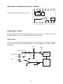
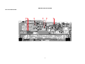
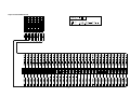
SK-60
36 SONG BANK
36 TONES
11
12
13
14
15
16
21
22
23
24
25
26
31
POWER
PIANO
ELEC PIANO
ORGAN
ACCORDION
GUITAR
VIBRAPHONE
VIOLIN
STRINGS
TRUMPET
CLARINET
SAX
FLUTE
SIREN 1
24 SONGS
@
32 SIREN 2
52 DOO1 (MALE)
33 TELEPHONE
53 DOO2 (MALE)
34 SPACE 1
54 BAH (BASS)
35 SPACE 2
55 BOM (BASS)
36 FUNNY
56 VOICE PERCUSSION
HUMAN VOICE
HUMAN VOICE
41 DOO (FEMALE) (CYCLE)
42 BEE (FEMALE) 61 DOO-BEE
43 DEE (FEMALE) 62 BOM-BAH
44 BAH (FEMALE) 63 DOO-BEE-DEE
45 AHH (CHOIR)
64 DOO-BEE-BAH
46 OOH (CHOIR)
65 DOO-BEE-DEE-BAH
51 LA (CHILDREN) 66 DOO-BEE-DOO-BAH
11
12
13
14
15
16
21
22
23
24
25
26
VOICES OF REASON (ORIGINAL SONG)
TWINKLE TWINKLE LITTLE STAR
DOOIN’ MY THING (ORIGINAL SONG)
ODE TO JOY
LITTLE BROWN JUG
SPRING FROM “THE FOUR SEASONS”
WHEN THE SAINTS GO MARCHING IN
FRÈRE JACQUES
OLD MacDONALD HAD A FARM
AULD LANG SYNE
LONDONDERRY AIR
ROW, ROW, ROW YOUR BOAT
31
32
33
34
35
36
41
42
43
44
45
46
MARY HAD A LITTLE LAMB
AMAZING GRACE
ACH DU LIEBER AUGUSTIN
LONDON BRIDGE
JOY TO THE WORLD
GREENSLEEVES
JINGLE BELLS
SILENT NIGHT
O CHRISTMAS TREE
YANKEE DOODLE
SANTA LUCIA
MARCH FROM “THE NUTCRACKER”
12 FREE SESSIONS
51
52
53
54
55
56
61
62
63
64
65
66
POPS 1
BIG BAND
SWING
FOX TROT
POPS 2
WALTZ 1
WALTZ 2
POLKA
SKA
TEX-MEX
COUNTRY
BAROQUE
ON
OFF
VOLUME TEMPO
1
2
3
TONE
START/ MELODY
STOP ON/OFF
MAGICAL
SINGER
PAD
EFFECT
PAD
SAMPLE
1
2
SA M
4
5
M
B
C
D
6 SONG BANK
3
TIME
S
A
1-2
1-2-3
EDIT
1-2-3-4
SAMPLING
EFFECT
TUNE
CYCLE
L
4
PLIN G MIC
RESET
RELEASE
REVERSE
LOOP
CLEAR
SK-60
ELECTRIONIC KEYBOARD
CONTENTS
Specifications .......................................................................................................................... 2
Block Diagram ......................................................................................................................... 3
Circuit Description ................................................................................................................... 4
Major Waveforms .................................................................................................................... 7
Printed Circuit Board ............................................................................................................... 8
Schematic Diagrams ............................................................................................................... 9
Exploded View ...................................................................................................................... 11
Parts List ............................................................................................................................... 13
SPECIFICATIONS
GENERAL
Number of keys:
Polyphonic:
Preset tones:
Human voice tones:
Voice cycles:
Song bank:
Free sessions:
Pads:
Pad settings:
Sampling method:
Sampling rate:
Sampling duration:
Tuning control:
Built-in speakers:
Terminals:
Power source:
Power consumption:
Dimensions(HWD):
Weight:
32
12-note
18
12
6
24-tune
12
4
Sampled sounds, effects, voice percussion
8-bit Differential Pulse Coded Modulation (DPCM)
13,021 kHz
2.4 seconds maximum
Approx. 440 Hz
4 inch dia. 2 W input rating: 2 pcs
7.5 V DC
2-way AC or DC source
AC: AC adapter
DC: 5 AA size dry batteries
2.0 W
416 × 222 × 530 mm (16-3/8 × 8-6/8 × 20-7/8 inches)
1.0 kg (2.2 lbs) excluding batteries
ELECTRICAL
Current drain with 7.5 V DC:
No sound output
50 mA ± 20%
Maximum volume
200 mA ± 20%
with white keys F4 to C6 pressed in Bah tone (No. 44)
Power off
80 µA (maximum)
Speaker output level (Vrms with 4 Ω load):
with key C4 pressed in Accordion tone
480 mV ± 20%
Volume: maximum
Minimum operating voltage
5.8 V
—2—
BLOCK DIAGRAM
RAM (256 Kbit)
LSI2
HM62256BLSP-8
MD0 ~ MD7
Mic. input
MA0 ~ MA14
KI4 ~ KI7
Mic. Amp.
Q105, Q106
Buttons
—3—
CPU
LSI1
Amp./Voltage Regulator
IC101
AN8053N
AVDD
VCC
KO0 ~ KO7
MSM6755B-10
Q103
APO
KI0 ~ KI3
DVDD
Voltage Regulator
Q101, Q102, D102
Power Supply Circuit
Keyboard
PG
Q1, X1
Reset IC
IC1
RE5VL40AA
CIRCUIT DESCRIPTION
KEY MATRIX
KI0
KI1
KI2
KI3
KI4
KI5
KI6
KI7
KO0 (SO0)
F3
C#4
A4
F5
A
1
1
Song
KO1 (SO1)
F#3
D4
A#4
F#5
B
2
2
Start/
Stop
KO2 (SO2)
G3
D#4
B4
G5
C
3
3
Melody
On/Off
KO3 (SO3)
G#3
E4
C5
G#5
D
4
4
Tone
KO4 (SO4)
A3
F4
C#5
A5
Volume
Up
Magical
Singer
5
KO5 (SO5)
A#3
F#4
D5
A#5
Volume
Down
Sampling
6
KO6 (SO6)
B3
G4
D#5
B5
Tempo
Up
Edit
Effect
KO7 (SO7)
C4
G#4
E5
C6
Tempo
Down
NOMENCLATURE OF KEYS
F#3 G#3 A#3
F3
G3
A3
B3
C#4 D#4
C4
D4
E4
F#4 G#4 A#4
F4
G4
A4
B4
—4—
C#5 D#5
C5
D5
E5
F#5 G#5 A#5
F5
G5
A5
B5
C6
CPU (LSI1: MSM6755B-10)
Containing a sound data ROM and a DAC (Digital to Analog Convertor), the CPU provides sound waveform
in accordance with the pressed key and the selected tone. The CPU also records the voice picked up the
microphone, using the built-in ADC (Analog to Digital Convertor) and the RAM.
The following table shows the pin functions of LSI1.
Pin No.
1
2
3
4 ~ 19
13
17
20 ~ 27
28, 29
30
31
32, 33
34
35
36
37
38
39
40
41
42, 43
44
45
46
47
48
49
50
51
52
53
54
55, 56
57
58 ~ 65
66 ~ 73
74 ~ 78
79
80 ~ 95
96
97 ~ 100
Terminal
MA14
MWEB
NC0
MA0 ~ MA13
MRDB
MCSB
MD0 ~ MD7
NC1, NC2
DGND
DVCC
XTL0, XTL1
NC3
RSTB
RXD
TXD
NMI
APO
NC4
REFH
NC5, NC6
DAOR
NC7
AVdac
DAOL
REFL
AGdac
AGadc
ANI
AVadc
NC8
MOD0
MOD1, MOD2
P40
KI0 ~ KI7
KO1 ~ KO8
—
LVCC
—
LGND
—
In/Out
Out
Out
—
Out
Out
Out
In/Out
—
In
In
In/Out
—
In
—
—
In
Out
—
Out
—
Out
—
In
—
Out
—
In
In
In
—
In
In
In
In
Out
—
In
—
In
—
Function
Address bus
Write enable signal output
Not used.
Address bus
Read enable signal output
Chip select signal for the RAM
Data bus
Not used.
Ground source
+5 V source
20 MHz clock input/output
Not used.
Reset signal input
Not used. Connected to +5 V.
Not used.
Power ON signal input
APO(Auto Power Off) signal output
Not used.
Terminal for the built-in DAC/ADC
Not used.
Sound waveform output
Not used.
+5 V source for the built-in DAC/ADC
Not used.
Terminal for the built-in DAC/ADC
Not used.
Ground source for the built-in ADC
Analog signal input
+5 V source for the built-in ADC
Not used.
Mode selection terminal
Mode selection terminal
APO cancellation signal input
Terminals for key/button input signal
Terminals for key scan signal
Not used.
+5 V source
Not used.
Ground source
Not used.
—5—
AMPLIFIER/VOLTAGE REGULATOR (IC101: AN8053N)
VCC
16
NC
15
5V
CONT VREG
14
13
The right figure shows the internal block of IC 101.
NC
12
NC
11
NC PRE GND
10
9
5V REG
POWER
–
SP AMP
+
1
SPO
2
3
4
5
NC SP GND PC-1 PC-2
VREF
6
7
8
SPI
SPM
VREF
POWER SUPPLY CIRCUIT
The power supply circuit generates two voltages DVDD (+5 V) and AVDD (+5 V). DVDD (+5 V) is always
generated but AVDD (+5 V) is controlled by APO signal output from the CPU.
OSCILLATOR
+5 V source of the oscillator is controlled by transistor Q107. When selecting the power switch at on position,
transistor Q107 turns on to become 20 MHz oscillation on. To keep the oscillation on, the CPU provides "H"
of APO signal.
DVDD
DVDD
From power switch
SWITCH: OFF
ON
+5 V
0V
"L"
"H"
APO:
+7.5 V
Oscillator
20 MHz
+5 V
0V
APO
—6—
CPU
MAJOR WAVEFORMS
1
2
3
1 Clock pulse
MSM6755B-10 pin 32
2 Key scan signal KO6
MSM6755B-10 pin 72
3 Key scan signal KO7
MSM6755B-10 pin 73
5
4
6
4 Sound waveform
MSM6755B-10 pin 44
Tone:
Key:
5 Mic. amp. input
Terminal PM-BL
6 Mic. amp. output
MSM6755B-10 pin 51
No. 22
A4
—7—
PRINTED CIRCUIT BOARD
Main PCB KDM415-MA1M
3
2
1
4
6
—8—
5
SCHEMATIC DIAGRAMS
Main PCB KDM415-MA1M/KY2M
5
4
1
6
3
—9—
2
Keyboard PCB KDM415-KY1M
— 10 —
EXPLODED VIEW
R-1
11
7
6
3
4
1
8
9
2
10
5
R-3
R-2
12
— 11 —
PARTS LIST
SK-60
Notes:
This parts list does not include the cosmetic parts, which
parts are marked with item No. "R-X" in the exploded
view.
Contact our spare parts department if you need these
parts for refurbish.
1.
Prices and specifications are subject to change without prior notice.
2.
As for spare parts order and supply, refer to the
"GUIDEBOOK for Spare parts Supply", published
seperately.
3.
The numbers in item column correspond to the same
numbers in drawing.
Item
1
LSI1
LSI2
IC1
IC101
Q102
Q107
D1
D101
D102
D103
D104
LED101
X1
J101
2
3
4
5
6
7
8
9
10
11
12
Code No.
Parts Name
Main PCB
6925 4540 Main PCB ass'y M415-MA1M
2012 3738 LSI, CPU
2012 3731 LSI, RAM
2105 5922 IC
2114 3269 IC
2220 1387 Transistor
2251 0469 Transistor
2200 2449 Transistor
2390 2828 Diode
2360 1554 Diode, Zener
2360 1085 Diode, Zener
2390 1323 Diode
2390 0371 Diode
2390 1344 Diode
2370 1106 LED
2590 1526 Creamic oscillator
3501 3780 Jack, Power
Keyboard PCBs
6925 4550 Keyboard PCB ass'y, M415KY1,2M
2390 1344 Diode
Mechanical Parts
3831 1064 Speaker
6909 5890 Slide contact
3830 9021 Microphone
6925 4560 Rubber button
6925 4570 Rubber button
6925 4580 Black key set, LNM32
6925 4590 White key set, NM32-B
6925 4600 Key contact rubber
6925 4610 Slide knob
6925 4620 Battery cover
Notes:
Q – Used quantity
R – Rank
— 13 —
Specification
Q R
M140426*1
MSM6755B-10
HM62256BLSP-8
RE5VL40AA-TZ
AN8053N
2SC1740SQ-TP-T
2SB1237Q,R-TV6-T
2SA933SQ-TP-T
RB441Q-40T-77
MTZJ5.1B-T77-T
HZS6B1LTD-T
RB100A-T32-T
DSK10B-BT-T
1SS133T-77-T
MPR3338S-B99
EFO-EN2005C4
HEC2305-01-250
1
1
1
1
1
5
1
1
1
1
1
1
1
20
1
1
1
M140427*1
1SS133T-77-T
1 B
32 C
S08JA32A
CSB-12D
WM-034CY
M240409-1
M240410-1
M110553-4
M140416-1
M240448-1
M311360-3
M311200*13
1
1
1
1
1
1
1
1
1
1
B
A
A
A
A
A
A
A
B
B
B
C
C
C
C
B
B
B
B
B
B
B
A
A
A
B
B
MA0700761A