1
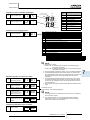
SET FREE SERIES
FSNM(E)
Service manual
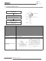
Outdoor Units: RAS-(8~12)FSNM(E)
Service Manual
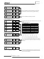
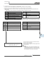
Contents
Units installation
0
1
Piping installation
2
Electrical wiring
3
Control system
4
Available optional functions
5
Test run
6
Troubleshooting
7
Spare parts
8
Servicing
9
Model codes and descriptions
Main parts
10
Field work instruction
11
SMGB0059 rev.0 - 04/2009
i
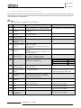
Service Manual
0.
Model codes and descriptions_____________________________________________ v
1.
Units installation________________________________________________________1
1.1
General installation notes________________________________________________________________ 2
1.2.
Transportation and handling______________________________________________________________ 4
1.2.1. Hanging method_ _________________________________________________________________________ 4
1.2.2. Center of gravity_ _________________________________________________________________________ 4
1.3.
Outdoor units installation________________________________________________________________ 5
1.3.1.
1.3.2.
1.3.3.
1.3.4.
2.
2.1.
Before installation_________________________________________________________________________
Installation location________________________________________________________________________
Service space____________________________________________________________________________
Foundations______________________________________________________________________________
5
6
7
9
Piping installation______________________________________________________ 11
Piping work considerations_ ____________________________________________________________ 12
2.1.1
2.1.2
2.1.3
2.1.4.
2.1.5.
Copper pipes and sizes____________________________________________________________________
Three principles on refrigerant piping work_____________________________________________________
Suspension of refrigerant piping_____________________________________________________________
Tightening torque_________________________________________________________________________
Brazing work____________________________________________________________________________
12
15
15
16
17
3.
Electrical wiring_ ______________________________________________________19
3.1.
General check_ ______________________________________________________________________ 20
3.2.
Electrical wiring for the outdoor unit_______________________________________________________ 21
3.2.1.Electrical wiring connection for outdoor unit_ _____________________________________________________ 21
3.2.2. Setting the DIP switches for the outdoor unit_ __________________________________________________ 22
3.3.
Common wiring_ _____________________________________________________________________ 25
3.3.1. Electrical wiring between the indoor unit and the outdoor unit_ _____________________________________ 25
3.4.
Wire size_ __________________________________________________________________________ 27
4.
Control system________________________________________________________29
4.1.
Device control system_ ________________________________________________________________ 30
4.1.1. RAS-8~10FSNM(E) refrigerant cycle control_ __________________________________________________ 30
4.2.
Outdoor Units PCB____________________________________________________________________ 32
4.2.1. RAS-8~12FSNM(E)_______________________________________________________________________ 32
5.
5.1.
Available optional functions______________________________________________33
Outdoor units________________________________________________________________________ 34
5.1.1.
5.1.2.
5.1.3.
5.1.4.
Setting of external input and output functions___________________________________________________
Description of external input signals__________________________________________________________
Description of external output signals_________________________________________________________
Optional functions________________________________________________________________________
34
36
39
41
6.
Test run_ ____________________________________________________________49
6.1.
Checking procedure before the test run ___________________________________________________ 50
6.2.
Test run procedure from the outdoor unit side_______________________________________________ 52
6.3.
Check list___________________________________________________________________________ 53
6.4.
Judgement system for refrigerant amount__________________________________________________ 56
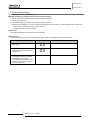
7.
Troubleshooting_______________________________________________________59
7.1.
Initial troubleshooting__________________________________________________________________ 60
7.1.1.
7.1.2.
7.1.3.
7.1.4.
Emergency operation_ ____________________________________________________________________
Failure of the power supply to the indoor unit and the remote control switch___________________________
Abnormal transmission between the remote control switch and the indoor unit_________________________
Abnormal operation of the devices___________________________________________________________
ii
SMGB0059 rev.0 - 04/2009
61
62
63
64
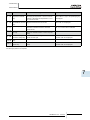
Service Manual
7.2.
Troubleshooting procedure_ ____________________________________________________________ 72
7.2.1.
7.2.2.
7.2.3.
7.2.4.
7.2.5.
7.2.6.
7.2.7.
8.
Alarm code indication of remote control switch__________________________________________________ 72
Troubleshooting by alarm code______________________________________________________________ 74
Troubleshooting in check mode______________________________________________________________115
Troubleshooting by means of the 7 segment display_ ___________________________________________ 121
Running current of the compressor__________________________________________________________ 127
Protection control code on the 7-segment display______________________________________________ 129
Activating condition of the protection control code_ _____________________________________________ 130
Spare parts__________________________________________________________132
8.1.
8.2.
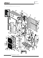
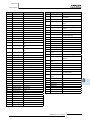
RAS-8~12FSNM(E) Structural and cycle parts_________________________________________________ 133
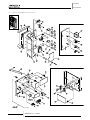
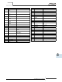
RAS-8~12FSNM(E) Electrical parts_ ________________________________________________________ 135
9.
Servicing_ __________________________________________________________137
9.1.
Outdoor Unit FSNM(E)________________________________________________________________ 138
9.1.1.
9.1.2.
9.1.3.
9.1.4.
9.1.5.
9.1.6.
9.1.7.
9.1.8.
9.1.9.
9.1.10
9.1.11.
9.1.12.
9.1.13.
9.1.14.
9.1.15.
9.1.16.
9.1.17.
9.1.18.
9.1.19.
Removing service cover_ _________________________________________________________________
Removing air outlet grille__________________________________________________________________
Removing upper cover_ __________________________________________________________________
Removing the lower part of service cover and rear cover_________________________________________
Removing outdoor fan motor_______________________________________________________________
Removing Electrical Box__________________________________________________________________
Removing compressor_ __________________________________________________________________
Removing high pressure switch____________________________________________________________
Removing high pressure sensor and low pressure sensor________________________________________
Opening electrical box (Power plate)________________________________________________________
Removing reversing valve coil and solenoid valve coil (SVA, SVF)_ ________________________________
Removing electronic expansion valve coil_____________________________________________________
Removing reversing valve_________________________________________________________________
Removing electronic expansion valve________________________________________________________
Removing solenoid valve_ ________________________________________________________________
Remove the control PCB (PCB1)_ __________________________________________________________
Removing Relay PCB (PCB3, PCB5)________________________________________________________
Removing inverter components_____________________________________________________________
Removing other inverter components________________________________________________________
138
138
138
139
139
140
142
145
146
146
147
148
149
150
151
152
152
153
155
10. Main parts_ _________________________________________________________157
10.1. Inverter____________________________________________________________________________ 158
10.1.1. Specifications of inverter__________________________________________________________________ 158
10.1. Inverter____________________________________________________________________________ 158
10.1.1.
10.1.2.
10.1.3.
10.1.4.
Specifications of inverter__________________________________________________________________
Inverter time chart_______________________________________________________________________
Protective Function______________________________________________________________________
Overload Control________________________________________________________________________
158
160
161
162
10.2. Thermistor_ ________________________________________________________________________ 163
10.2.1. Position of thermistor_____________________________________________________________________ 163
10.2.2. Resistance value of the thermistor_ _________________________________________________________ 163
10.3. Electronic expansion valve_____________________________________________________________ 166
10.3.1. Electronic expansion valve for the outdoor unit_________________________________________________ 166
10.4. Pressure sensor_____________________________________________________________________ 167
10.5. Scroll compressor_ __________________________________________________________________ 168
10.5.1. Reliable mechanism for low vibrating and low sound____________________________________________ 168
10.5.2. Principle of compression__________________________________________________________________ 168
11. Field work instruction__________________________________________________169
11.1. Checking the power source and the wiring connection_______________________________________ 170
11.2. Burnt-out compressor due to an insufficient refrigerant charge_________________________________ 170
11.3. Insufficient cooling performance when a long piping is applied_________________________________ 171
11.4. Abnormally high operation sound (in-the-ceiling type indoor unit)_______________________________ 171
11.5. Alarm Code "31"_____________________________________________________________________ 172
11.6. Not cooling well due to insufficient installation space for the outdoor unit_________________________ 172
SMGB0059 rev.0 - 04/2009
iii
0
1
2
3
4
5
6
7
8
9
10
11
Service Manual
11.7. Guideline for selecting the drain pipe for the indoor unit______________________________________ 173
11.8. Caution with the refrigerant leakage_ ____________________________________________________ 174
11.8.1. Maximum permissible concentration of the HCFC Gas__________________________________________ 174
11.8.2. Calculation of the refrigerant concentration____________________________________________________ 174
11.8.3. Countermeasure for the refrigerant leakage according to the KHK standard__________________________ 174
11.9. Maintenance work_ __________________________________________________________________ 175
11.10. Service and maintenance record________________________________________________________ 176
11.11. Service and maintenance record by means of the 7-segment display____________________________ 177
11.11.1.Data Sheet for Checking by 7-Segment Display________________________________________________ 177
11.11.2.Pump-down method for replacing the compressor______________________________________________ 179
iv
SMGB0059 rev.0 - 04/2009
Model codes and
decriptions
Service Manual
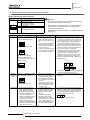
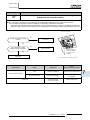
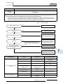
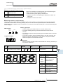
0. Model codes and descriptions
¡¡ Unit code list
Please check by model name your air conditioner type, its abbreviation and reference number
MODEL CODIFICATION in this service manual.
FSN(2)(E) INDOOR UNITS
4-Way Cassette
4-Way Mini Cassette
2-Way Cassette
Unit
Code
Unit
Code
Unit
Code
RCI-1.0FSN2E
7E400001
RCIM-1.0FSN2
60278011
RCD-1.0FSN2
60278029
RCI-1.5FSN2E
7E400002
RCIM-1.5FSN2
60278013
RCD-1.5FSN2
60278030
RCI-2.0FSN2E
7E400003
RCIM-2.0FSN2
60278014
RCD-2.0FSN2
RCI-2.5FSN2E
7E400004
RCI-3.0FSN2E
Ceiling
Unit
Code
60278031
RPC-2.0FSNE
7E440003
RCD-2.5FSN2
60278032
RPC-2.5FSN2E
7E440004
7E400005
RCD-3.0FSN2
60278033
RPC-3.0FSN2E
7E440005
RCI-4.0FSN2E
7E400007
RCD-4.0FSN2
60278034
RPC-4.0FSN2E
7E440007
RCI-5.0FSN2E
7E400008
RCD-5.0FSN2
60278035
RPC-5.0FSN2E
7E440008
RCI-6.0FSN2E
7E400009
RPC-6.0FSN2E
7E440009
RCI
RCIM
RCD
RPC
1~
Meaning of model codification:
RPI
3.0
FS
N
2
E
Unit Type (Indoor Unit RCI(M), RCD,
RPC, RPI, RPK, RPF(I))
Compressor power (HP) 1.0 ~ 6.0
H-Link Set Free / System Free
R410 A refrigerant
Series
E: Made in Europe
- Made in Malaysia
SMGB0059 rev.0 - 04/2009
v
0
Model codes and
decriptions
Service Manual
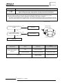
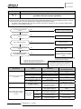
FSN(2)(E) INDOOR UNITS
Duct
Unit
Code
Wall
Unit
Code
Unit
Code
Floor Enclosure
Floor Concealed
Enclosure
Unit
Code
Unit
Code
RPK-1.0FSNH2M 60277942
RPI-0.8FSN2E
7E420000
RPIM-0.8FSN2E
7E430000
RPI-1.0FSN2E
7E420001
RPIM-1.0FSN2E
7E430001
RPK-1.0FSN2M
60277941 RPF-1.0FSN2E
7E450001
RPFI-1.0FSN2E
7E460001
RPI-1.5FSN2E
7E420002
RPIM-1.5FSN2E
7E430002
RPK-1.5FSN2M
60277942 RPF-1.5FSN2E
7E450002
RPFI-1.5FSN2E
7E460002
RPI-2.0FSN2E
7E420003
RPK-2.0FSN2M
60277943 RPF-2.0FSN2E
7E450003
RPFI-2.0FSN2E
7E460003
RPI-2.5FSN2E
7E420004
RPK-2.5FSN2M
60277944 RPF-2.5FSN2E
7E450004
RPFI-2.5FSN2E
7E460004
RPI-3.0FSN2E
7E420005
RPK-3.0FSN2M
60277945
-
-
-
RPI-4.0FSN2E
7E420007
RPK-4.0FSN2M
60277946
RPI-5.0FSN2E
7E420008
RPI-6.0FSN2E
7E420009
RPI-8.0FSN2E
7E420010
RPI-10.0FSN2E
7E420011
RPI
RPK-1.5FSNH2M 60277942
RPIM
RPK
RPF
1~
Meaning of model codification:
RPF
2.0
FS
Unit Type (Indoor Unit RCI(M), RCD,
RPC, RPI, RPK, RPF(I))
Compressor power (HP) 1.0 ~ 6.0
H-Link Set Free / System Free
R410 A refrigerant
Series
E: Made in Europe
- Made in Malaysia
vi
SMGB0059 rev.0 - 04/2009
N
-
2
E
RPFI
Model codes and
decriptions
Service Manual
0
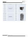
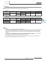
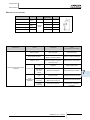
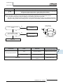
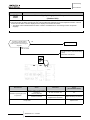
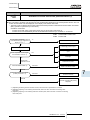
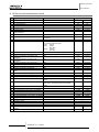
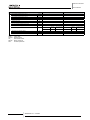
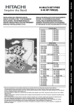
FSNM(E) OUTDOOR UNITS (SET FREE SIDE FLOW TYPE)
Unit
Code
RAS-8-FSNM(E)
60288308
RAS-10FSNM(E)
60288309
RAS-12FSNM(E)
60288310
RAS
3~
Meaning of model codification:
RAS
10
FS
N
M
Unit Type (Outdoor Unit)
Compressor power (HP) 8 -10-12
Set-Free System 2 pipes
R410 A refrigerant
Series (Side Flow)
SMGB0059 rev.0 - 04/2009
vii
Model codes and
decriptions
Service Manual
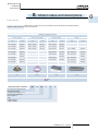
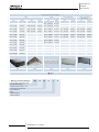
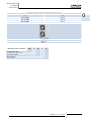
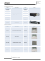
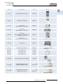
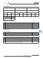
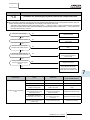
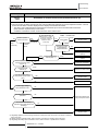
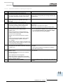
¡¡ Complementary systems
Name
Description
Code
KPI-502E1E
70600001
KPI-802E1E
70600002
KPI-1002E1E
70600003
Energy recovery ventilation units
KPI-1502E1E
70600004
KPI-2002E1E
70600005
KPI-3002H1E
70600107
EF-5NE
Figure
Econofresh kit
7E774148
Name
Description
Code
PC-ART
Remote control switch with timer
70510000
PSC-A64S
Central control
60291479
PSC-A16RS
Centralized ON/OFF controller
60291484
PSC-A1T
Programmable timer
60291482
¡¡ List of accessories
viii
SMGB0059 rev.0 - 04/2009
Figure
Model codes and
decriptions
Service Manual
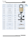
Name
Description
Code
Figure
PC-LH3A
Wireless remote control switch
60291056
PC-ARH
Optional remote controller
60291486
PC-ALH
Receiver kit
(for RCI-FSN2E -on the panel-)
60291464
PC-ALHD
Receiver kit
(for RCD-FSN2· -on the panel-)
60291467
PC-ALHZ
Receiver kit
(for RCI, RCD, RPC, RPI, RPK, RPF(I) (FSN2(E)) -on the wall-)
60291473
PC-ALHC
Receiver kit
(for RCIM-FSN2 -on the panel-)
60291476
PSC-5HR
H-LINK relay
60291105
PCC-1A
Optional function connector
60199286
PRC-10E1
2-pin extension cord
7E790211
PRC-15E1
2-pin extension cord
7E790212
PRC-20E1
2-pin extension cord
7E790213
PRC-30E1
2-pin extension cord
7E790214
THM-R2AE
Remote temperature sensor (THM4)
7E299907
HC-A32MB
Building Management System
Gateway to MODBUS systems.
7E513200
HC-A16KNX
Building Management System
Gateway to KNX systems.
7E513300
Image not available
NEW
NEW
SMGB0059 rev.0 - 04/2009
ix
0
Model codes and
decriptions
Service Manual
Name
Description
Buildin g Management System
Gateway to LONWORKS systems.
(max. 64 IU, 8 parameters)
Building Management System
Gateway to LONWORKS systems.
(max. 32 IU, 16 parameters)
HARC-BXE (A)
HARC-BXE (B)
Code
60290874
60290875
HC-A64BNP
Building Management System
Gateway to BAC Net system.
60291569
CSNET-WEB (v3)
Control System
7E891938
TS001 WEB SCREEN
15-inch touch-screen display
7E891935
PC-A-1I0
Integration of teams into H-LINK
7E519000
HC-A160SMS
SMS alarm warning device
7E519100
DBS-26
Drain discharge connection
60299192
P-N23WA
Air panel
for RCI-FSN2E
70530000
P-N23WAM
Air panel
for RCIM-FSN2E
60197160
P-N23DWA
Air panel
for RCD-FSN2E
60291574
P-N46DWA
Air panel
for RCD-FSN2E
60291575
x
SMGB0059 rev.0 - 04/2009
Figure
Model codes and
decriptions
Service Manual
Name
Description
Code
B-23H4
Adapter for deodorant filter
60199790
F-23L4-K
Antibacteria filter
60199791
F-23L4-D
Deodorant filter
60199793
F-46L4-D
Deodorant filter
60199794
PDF-23C3
Duct connection flange
60199795
PDF-46C3
Duct connection flange
60199796
OACI-232
Fresh-air intake kit
60199797
PD-75
Fresh-air intake kit
60199798
PI-23LS5
3-way outlet parts
60199799
TKCI-232
T-duct connecting kit
60199801
MW-102AN
Figure
70522001
MW-162AN
70522002
Branch pipe
MW-242AN
70522004
MW-302AN
70522005
MH-84AN
70522007
Header
MH-108AN
70522008
SMGB0059 rev.0 - 04/2009
xi
0
Model codes and
decriptions
Service Manual
Name
Description
Code
HR-500
70550101
HR-800
70550102
Energy exchanger for KPI
(heat recovery)
HR-1000
70550103
HR-1500
70550104
HR-2000
70550105
STL-30-200-L600
70550200
STL-30-250-L600
70550201
Sound attenuator
(Heat/energy recovery)
STL-30-300-L600
70550202
STL-30-355-L600
70550203
STL-30-450-L600
70550204
xii
SMGB0059 rev.0 - 04/2009
Figure
Units installation
Service Manual
1. Units installation
This chapter provides information about the procedures you must follow to install the Set-Free FSNM(E) outdoor units.
Contents
1. Units installation_ ____________________________________________________________ 1
1.1
General installation notes_____________________________________________________ 2
1.2. Transportation and handling___________________________________________________ 4
1.2.1. Hanging method_________________________________________________________________ 4
1.2.2. Center of gravity_________________________________________________________________ 4
1.3. Outdoor units installation_____________________________________________________ 5
1.3.1.
1.3.2.
1.3.3.
1.3.4.
Before installation________________________________________________________________
Installation location_______________________________________________________________
Service space___________________________________________________________________
Foundations____________________________________________________________________
SMGB0059 rev.0 - 04/2009
1
5
6
7
9
1
Units installation
Service Manual
1.1General installation notes
warning
Install the outdoor unit with sufficient clearance around it for operation and maintenance as shown in the next
pages.
Install the outdoor unit where good ventilation is available.
Do not install the outdoor unit where exists a high level of oil mist, salty air or sulphurous atmosphere.
Install the outdoor unit as far as practical (being at least 3 meters) from electromagnetic wave radiator, such as
medical equipment.
Keep clearance between units of more than 50 mm, and avoid obstacles that could hamper air intake, when
installing more than one unit together.
Install the outdoor unit in the shade or not exposed to direct sunshine or direct radiation from high temperature
heat source.
Do not install the outdoor unit in a place where a seasonal wind directly blows into the outdoor fan.
For cleaning, use non-inflammable and nontoxic cleaning liquid. Use of inflammable agent may cause explosion or
fire.
Work with sufficient ventilation, for working in an enclosed space could cause oxygen deficiency. Toxic gas may be
produced when cleaning agent is heated to high temperature by, e.g., being exposed to fire.
Cleaning liquid shall be collected after cleaning.
Pay attention not to clamp cables when attaching the service cover to avoid electric shock or fire.
caution
Check the foundation to be flat, leveled and strongly enough.
Install the unit in a restricted area not accessible by the general public.
Aluminium fins have very sharp edges. Pay attention to the fins in order to avoid injury.
Do not install the indoor units in a flammable environment to avoid a fire or an explosion.
Check to ensure that the ceiling slab is strong enough. If not strong enough, the indoor unit may fall down on you.
Do not install the indoor units, outdoor unit, remote control switch and cable within approximately 3 meters from
strong electromagnetic wave radiators, such as medical equipment.
Do not install the indoor units in a machinery shop or kitchen, where vapor from oil or mist flows to the indoor units.
The oil will deposit on the heat exchanger, thereby reducing the indoor unit performance, and may deform. In the
worst case, the oil damages the plastic parts of the indoor unit.
To avoid any corrosive action to the heat exchangers, do not install the indoor units in an acid or alkaline
environment.
When lifting or moving the indoor unit, use appropriate slings to avoid damage and be careful not to damage the
insulation material on units surface.
This appliances are not intended for use by people (including children) with reduced physical, sensory or mental
capabilities, or lack of experience and knowledge, unless they have been given supervision and instruction
concerning the use of the appliance by a person responsible for their safety.
Turn OFF all power switches before maintenance is performed.
Do not start the cleaning procedures before 5 minutes of the stop of the unit.
warning
Check and ensure that the accessories are packed with the indoor unit.
Do not install the indoor units outdoors. If installed outdoors, an electric hazard or electric leakage will occur.
Consider the air distribution from each indoor unit to the space of the room, and select a suitable location so that
uniform air temperature in the room can be obtained. It is recommended that the indoor units be installed 2.3 to 3
meters from the floor level. If the unit is installed higher than 3 meters, it is also recommended to use a fan in order
to obtain an uniform air temperature in the room.
Avoid obstacles which may hamper the air intake or the air discharge flow.
Children must be supervised to ensure that they do not play with the electrical appliances.
Before obtaining access to terminals, all supply circuits bust be disconnected.
2
SMGB0059 rev.0 - 04/2009
Units installation
Service Manual
warning
Pay attention to the following points when the indoor units are installed in a hospital or other places where there
are electronic waves from medical equipment and similar.
Do not install the indoor units where electromagnetic wave is directly radiated to the electrical box, remote control
cable or remote control switch.
Install the indoor units and components as far as practical or at least 3 meters from the electromagnetic wave
radiator.
Prepare a steel box and install the remote control switch in it. Prepare a steel conduit tube and wire the remote
control cable in it. Then connect the ground wire with the box and tube.
Install a noise filter when the power supply emits harmful noises.
This unit is exclusive non electrical heater type indoor unit. It is prohibited to install a electrical heater in the field.
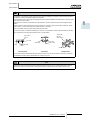
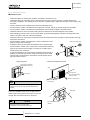
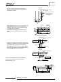
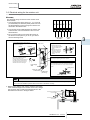
Mount suspension bolts using M10 (W3/8) as size, as shown below:
Wooden Bar
(60mm to
90mm square)
Insert (100 to
150 kg)
Concrete
Anchor bolt
(W3/8 or M10)
Steel beam
Steel
Anchor bolt (W3/8
or M10)
Wooden Beam
Concrete Beam
Steel Beam
Wooden Beam
Do not put any foreign material into the indoor unit and check to ensure that none exist in the indoor unit before
the installation and test running. Otherwise a fire or failure may occur.
Note
Hitachi indoor units are designed for free air discharge (Static Pressure, Pst=0), except ducted indoor units as
RPIM, which require to be connected to discharge air ducts. For these units see flow-static pressure chart.
SMGB0059 rev.0 - 04/2009
3
1
Units installation
Service Manual
1.2.Transportation and handling
Transport the product as close to installation location as practical before unpacking.
caution
- Do not put any material on the product.
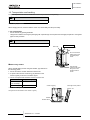
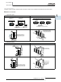
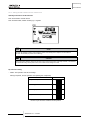
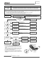
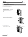
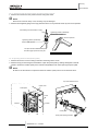
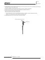
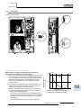
1.2.1. Hanging method
When hanging the unit, ensure a balance of the unit, check safety and lift up smoothly.
For transportation
- Do not remove any packing materials.
- Hang the unit without removing the packaging with ropes through each square hole and apply the splints or corrugated
paper for unit protection
DANGER
- Do not tie ropes at the wooden base..
Wire rope
Over 60º
0.7 to 1.0 m
Do not remove the
plastic band or the
corugated paper
frame
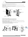
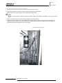
nWhen Using Handles
When manually lifting the unit using the handles, pay attention to
the following points.
1 Do not remove the wooden base from outdoor unit.
Pass the wire
ropes through each
lifting hole in the
wooden base as
shown.
2 To prevent the unit from overturning, pay attention to the
center of gravity as shown in the below figure.
3 Two or more personnel should be used to move the unit.
Model
Unit gross weight (kg)
RAS-8FSNM(E)
RAS-10FSNM(E)
179
RAS-12FSNM(E)
182
Center of gravity
1.2.2. Center of gravity
Approx. 20º
The figure shows the location of the center of gravity
Handle
Wooden base
4
Fall angle of this product
SMGB0059 rev.0 - 04/2009
Units installation
Service Manual
1.3.Outdoor units installation
WARNING
– Install the outdoor unit with sufficient clearance around it for operation and maintenance as
shown in the next figures.
– Install the outdoor unit where good ventilation is available
– Do not install the outdoor unit where is a high level of oil mist, salty air or sulphurous
atmosphere.
– Install the outdoor unit as far as practical (being at least 3 meters) from electromagnetic wave
radiator (such as medical equipment).
– Keep clearance between the units of more than 50 mm, and avoid obstacles that may hamper
air intake, when installing more than one units together.
– Install the outdoor unit in the shade or not exposed to direct sunshine or direct radiation from
high temperature heat source.
&
CAUTION
– Check to ensure that the foundation is flat, level and sufficiently strong.
– Install the unit in a restricted area not accessible by the general public
– Aluminum fins have very sharp edges. Pay attention to the fins to avoid injury.
&
CAUTION
Pay attention to the followings to run through the cables under the unit using conduit for piping
and wiring works. (The pipe cover is required to remove before performing piping and wiring
works.)
1. Attach the pipe cover to avoid entering rats or other small animals into the unit.
2. Completely seal the conduit inlet with sealing materials.
3. Make a drain hole at the lowest part of the conduit.
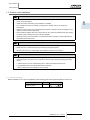
1.3.1. Before installation
Before installation work, check the availability of the following parts that are packed inside the outdoor unit
Accessory
Pipe with flare nut for
refrigerant piping
Quantity
Purpose
1
SMGB0059 rev.0 - 04/2009
5
1
Units installation
Service Manual
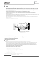
1.3.2. Installation location
nInstallation place
– Install the outdoor unit where good ventilation is available, and where it is dry.
– Install the outdoor unit where the sound or the discharge air from the outdoor unit does not affect neighbors or
surrounding vegetation. The operating sound at the rear or right/left sides is higher than the value in the catalog at the
front side.
– Check to ensure that the foundation is flat, level and sufficiently strong.
– Do not install the outdoor unit where there is a high level of oil mist, salty air or harmful gases such as sulphur.
– Do not install the outdoor unit where the electromagnetic wave is directly radiated to the electrical box.
– Install the outdoor unit as far as practical, being at least 3 meters from the electromagnetic wave radiator.
– When installing the outdoor unit in snow-covered areas, mount the field-supplied hoods at the discharge side of the
outdoor unit and the inlet side of the heat exchanger.
– Install the outdoor unit where it is in the shade or it will not be exposed to direct sunshine or direct radiation from high
temperature heat source.
– Do not install the outdoor unit where dust or other contamination could
block the outdoor heat exchanger.
Direction of Strong Wind
– Install the outdoor unit in a space with limited access to general public.
– Do not install the outdoor unit in a space where a seasonal wind directly
blows to the outdoor heat exchanger or a wind from a building space
directly blows to the outdoor fan
– In case of installation in the open spaces unavoidably where there is no
buildings or surrounding structures, adopt the wind guard set or install
near the wall to avoid facing the wind directly. Ensure that the service
space should be secured.
Using wind guard
Direction of Air Discharge
A wall to guard againts the wind
Wind guard set (optional)
Model WSP-335A (2 pcs.)
Wall
Air intake side
(Face the air discharge
side to the wall)
Strong wind
Direction od strong wind
?
Note
Secure the adequare
service space
If the extreme strong wind blows directly against the air
discharge portion, the fan may rotate reversely and be
damaged.
Wire rope
If the unit is installed on the roof or the place forced
directly against strong wind such as storm, fix the unit
securely with wire ropes as shown in the figure.
&
CAUTION
Aluminum fins have very sharp edges.
Pay attention to the fins to avoid any injury.
6
SMGB0059 rev.0 - 04/2009
Snow protection hood
(option)
Units installation
Service Manual
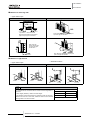
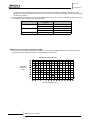
1.3.3. Service space
Install the outdoor unit with a sufficient space around the outdoor unit for operation and maintenance as shown below.
nObstacles on inlet side
– Upper side is open
Single installation
* Around sides
are open
Multiple installation
* Around sides
are closed
Front side
*
Front side
Front side
*
Front side
Note: Open both right and left sides
Fit positions “*” with front side
Note: Mount the airflow
(optional part) and open
both right and left sides.
Note: Mount the airflow
(optional part) and open
both right and left sides.
– Obstacles in above
Single installation
Multiple installation
Note: Open both
right and left sides
Note: Mount the
airflow (optional
part) and open
both right and
left sides.
Note: Mount the airflow
(optional part) and open
both right and left sides.
SMGB0059 rev.0 - 04/2009
7
1
Units installation
Service Manual
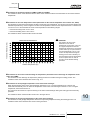
nObstacles on discharge side
– Upper side is open
Single installation
Multiple installation
Front side
*
*
Fit positions “*” with unit front side
Note: Mount the airflow (optional part) and
open both right and left sides.
Note: Mount the airflow guide (optional
part) and open right end or left end.
Note: Mount the
airflow (optional part)
and open both right
and left sides.
Note: Mount the airflow (optional part) and
open both right and left sides.
nObstacles in right and left
– Obstacles in above
– Upper side is open
Single installation
?
Multiple installation
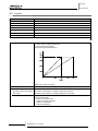
Note
If L is higher than H, mount the units on a base so that H is greater or
equal to L.
H: Unit Height (1650mm) + Base Concrete Height
In this situation ensure that the base is closed and does not allow the
airflow to short circuit. In each case, install the outdoor unit so that the
discharge flow is not short-circuited.
8
SMGB0059 rev.0 - 04/2009
L
A
0 < L ≤ 0.5H
600 or more
0.5H < L ≤ H
1400 or more
Units installation
Service Manual
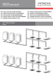
nMulti-row and multiple installations
1
Keep a distance of more than 100mm between other units and
do not put obstacles on the right and left sides. Dimension B is
as shown beside.
?
L
A
B
0 < L ≤ 0.5H
600 or more
300 or more
0.5H < L ≤ H
1400 or more
350 or more
Note
If L is larger than H, mount the units on a base o that H is greater or equal to L.
In this situation ensure that the base is closed and does not allow the airflow to short circuit..
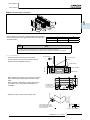
1.3.4. Foundations
Air flow direction
– Secure the outdoor unit with the anchor bolts.
Base of outdoor unit
– Fix the outdoor unit to the anchor bolts by special
washer of factory-supplied accessory.
Nut
Max. 21 mm
Special washer
Anchor bolt M12
Filled mortar
– When installing the outdoor unit, fix the unit by anchor
bolts. Refer to figure regarding the location of fixing
holes.
When the mark * dimension is secured, piping work
from bottom side is easy without interference of
foundation.
4-Ø16x23.5 hole
for anchor bolt
Max- 21 mm
(after cut “A”)
– Example of fixing outdoor unit by anchor bolts.
Cut this portion when this
type of anchor bolt is used.
If not, it is difficult to remove
the service cover.
Concrete
SMGB0059 rev.0 - 04/2009
9
Anchor bolt
Units installation
Service Manual
– (4) Fix the outdoor unit firmly so that declining,
making noise, and falling down by strong wind or
earthquake is avoided.
Fixing plate
(Field supplied)
Both sides of the unit fixing
can be possible
When vibration measures
are necessary, add
vibration proof rubber.
(Field-Supplied)
Air inlet
– When installing the unit on a roof or a veranda, drain
water sometimes turns to ice in a cold morning.
Therefore, avoid draining in an area where people
often use because it is slippery.
Drain hole
(3-Ø24)
– In case of the drain piping is necessary for the
outdoor unit, use the drain-kit (DBS-26: Optional
Parts)
Drain hole (2-Ø26)
(Drain boss attaching position)
Incorrect
Base width of outdoor unit
100 mm
Outdoor unit
is unstable
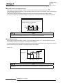
– The whole of the base of the outdoor unit should be
installed on a foundation. When using vibration-proof
mat, it should also be positioned the same way.
Frame
When installing the outdoor unit on a field supplied
frame, use metal plates to adjust the frame width for
stable installation as shown in the figure.
Frame width 60 mm
(Field supplied)
Correct
Base width of outdoor unit
100 mm
Outdoor unit
is stable
Recommended Metal Plate Size (Field-Supplied)
Material: Hot-Rolled Mild Steel Plate (SPHC)
Plate Thickness: 4.5T
Frame
Metal plate
Metal plate
100 mm or more
2- Long hole
10
SMGB0059 rev.0 - 04/2009
Piping installation
Service Manual
2. Piping installation
Contents
2. Piping installation_ __________________________________________________________ 11
2.1. Piping work considerations_ _________________________________________________ 12
2.1.1
2.1.2
2.1.3
2.1.4.
2.1.5.
Copper pipes and sizes__________________________________________________________
Three principles on refrigerant piping work_ __________________________________________
Suspension of refrigerant piping____________________________________________________
Tightening torque_______________________________________________________________
Brazing work___________________________________________________________________
SMGB0059 rev.0 - 04/2009
11
12
15
15
16
17
2
Piping installation
Service Manual
2.1.Piping work considerations
2.1.1 Copper pipes and sizes
1. Prepare locally-supplied copper pipes.
2. Select the piping size with the correct thickness and correct material which can have sufficient pressure strength. Use the
table below to select the required pipe.
Nominal Diameter
(mm)
6.35
9.53
12.70
15.88
19.05
22.23
25.40
28.60
31.75
34.93
38.10
41.28
44.45
(in)
1/4
3/8
1/2
5/8
3/4
7/8
1
1 1/8
1 1/4
1 3/8
1 1/2
1 5/8
1 3/4
Thickness
(mm)
Copper type
0.80
0.80
0.80
1.00
1.00
1.00
1.00
1.00
1.10
1.25
1.35
1.20
1.55
Roll
Roll
Roll
Roll
Pipe
Pipe
Pipe
Pipe
Pipe
Pipe
Pipe
Pipe
Pipe
Note
- In case of using copper pipes for piping sections bigger than Ø 19.05 mm (3/4 inches), flaring work cannot be
performed. If necessary, use a joint adapter.
3.Select clean copper pipes. Make sure there is not dust and moisture inside. Blow the inside of the pipes with oxygen free
nitrogen to remove any dust and foreign materials before connecting the pipes.
4.After connecting the refrigerant piping, seal the open space between Knockout hole and refrigerant pipes by using
insulation material as shown below:
Insulation material
Field supplied refrigeration pipe
Unit side
Insulation material
Insulation material
caution
- Do not use a saw and a grindstone or other tools which cause copper powder.
- When cutting pipes, secure the part for brazing in accordance with both national and local regulations.
- Use security glasses and gloves for cutting or welding works.
12
SMGB0059 rev.0 - 04/2009
Piping installation
Service Manual
nPiping Connection
When connecting liquid piping for units with piping longer than 15 meters, apply a piping size of Ø9.53 mm (3/8 inches).
Fix the connecting pipe as shown in the following figure using the insulation attached to the Indoor Unit.
Use the flare nut of the indoor unit
Fix this part with
the attached cord
band or with tape
Insulate this part with the
attached insulation
Field-supplied
refrigerant piping
Insulation
attached to
indoor unit
Make flares after
attaching flare nut to
the connecting pipe in
the multi-kit package
Brazing
Field-supplied insulation
Note
-A system with no moisture or oil contamination will give maximum performance and lifecycle compared to a
poorly prepared system. Take particular care to ensure that all copper piping is clean and dry internally.
- To ensure this, blow oxygen-free nitrogen through the pipes.
caution
- When inserting a pipe through any hole protect the end with a cap.
- Do not put pipes on the ground directly without a cap or vinyl tape at the end of the pipe
-If the piping installation is not completed until the next day or even over a longer period of time, braze off the
ends of the piping and charge the pipe with oxygen-free nitrogen through a Schrader-valve-type access-fitting,
to prevent moisture and particle contamination entering.
-Do not use insulation material that contents NH3. NH3 can damage the cooper pipe material and can be a
source of future leakages
Correct
Incorrect
SMGB0059 rev.0 - 04/2009
13
2
Piping installation
Service Manual
• Insulation
Attach the pipe insulation to each branch using vinyl tape. Attach also insulation to field supplied pipes in order to prevent
the capacity decrease according to the ambient air conditions and dewing on the low pressure pipe surface.
Field supplied insulation
Cap
Do not make a gap
Cap
Cap
Note
-When polyethylene foam is applied, it is recommended the usage of a wall thickness of 10 mm for the liquid
piping and 15 mm to 20 mm for the gas piping.
caution
-Perform the insulation work after the pipe surface temperature decreases to the room temperature, if not the
insulation material may melt.
-If the ends of the piping system are open after ending the piping work, attach caps or vinyl bags securely to the
ends of the piping, avoiding moisture and dust entering.
14
SMGB0059 rev.0 - 04/2009
Piping installation
Service Manual
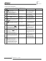
2.1.2 Three principles on refrigerant piping work
In case of using refrigerant R410A in the refrigeration cycle, the refrigeration oil should be of a synthetic type one.
In order to avoid oxidation, pay much careful attention to basic piping work control to avoid infiltration of moisture or dust
during the refrigerant piping work.
Three principles
1. Dry
Keep good dryness
2. Clean
No dust Inside of pipes
Cause of failure
- Water infiltration due to insufficient
protection at pipe ends
- Dewing inside of pipes
- Insufficient vacuum pumping time
- Infiltration of dust or other through
the pipe ends
- Oxidation film during brazing
without blowing nitrogen
- Insufficient flushing by nitrogen
after brazing
Presumable failure
Icing inside tube at ex. valve
(Water choking)
+
Generation of hydration and
oxidation of oil
↓
Clogged Strainer, etc., insulation
failure and compressor failure
No leakage shall exist
- Brazing failure
- Failed flaring work and insufficient
torque of squeezing flare
- Insufficient torque of squeezing
flanges
Pipe protection
1 Pinching
2 Taping
↓
Flushing
↓
Vacuum Drying
- One gram of water turns
into gas (approx. 1000 lrs)
at 1 Torr
- Therefore, it takes long
time to vacuum-pump by a
small vacuum pump
Clogging of expansion valve,
capillary tube and filter
Pipe Protection
1 Mounting Caps
2 Taping
3 Pinching
↓
Flushing
Oxidation of oil
Compressor failure
↓
Insufficient cooling or heating
compressor failure
Refrigerant shortage
3. No leakage
Preventive action
Performance decrease
Oxidation of oil
Overheating of compressor
↓
Insufficient cooling or heating
compressor failure
Careful Basic Brazing Work
↓
Basic Flaring Work
↓
Basic Flange Connecting
Work
↓
Air Tight Test
↓
Holding of Vacuum
2.1.3 Suspension of refrigerant piping
Suspend the refrigerant piping at certain points and prevent
the refrigerant piping from touching weak parts of the
building such as walls, ceiling, etc. (If touched, abnormal
noises may occur due to the vibration of the piping. Pay
special attention in case of short piping length).
1~15m
Fire-proof
section
treatment
In order to fix the piping to wall or ceilings use suspension
and clamping systems as shown in the following figure.
Indoor unit
SMGB0059 rev.0 - 04/2009
15
2
Piping installation
Service Manual
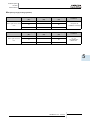
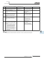
2.1.4. Tightening torque
1. Flaring connections (smaller than a diameter of Ø19.05) are generally used. However, if incorrect flaring is performed, it
will cause serious refrigerant leakage.
2. Shape after Flaring, it should be rectangular and flat, and no uneven thickness, cracks and scratches should exist.
Nominal diameter Ød
Dimension
(inches)
(mm)
A+0.0/-0.4 (mm)
1/4
3/8
1/2
5/8
3/4
6.35
9.53
12.70
15.88
19.05
9.1
13.2
16.6
19.7
(*)
(*) It is impossible to perform the flaring work. In this case, use a joint selected from the table in point 3.
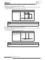
When tightening the flare nuts, use two spanners, as shown in the figure.
Pipe diameter (mm)
Size B (R410A)
Tightening torque (Nm)
Ø6.35
17
20
Ø9.53
22
40
Ø12.70
26
60
Ø15.88
29
80
Ø19.05
36
100
Stop valve FSNM(E)
Gas valve
Tighten the cap with the torque at
30N·m after this work.
Refrigerant pressure
Liquid valve
Charge port cap
Tightening torque: 26N·M
Liquid valve
Do not apply
two spanners at
this portion. If
applied, leakage
will occur.
O-ring
(rubber)
Check joint
Only the charging hose can be
connected.
Tighten the cap with the torque
at 13N·m
Refrigerant piping
Use two
spanners here
to squeeze flare
nut.
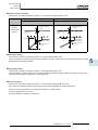
? Note
1 This valve is a ball valve.
The stem is turned to arrow direction for valve open
and close as below.
2 Use adjustable wrench for the stem operation.
Turn the stem until contact to the pin.
3 Attach the ring securely after the stem operation.
4 Do not leave the stem at half opening position.
16
SMGB0059 rev.0 - 04/2009
Cap
Tightening torque: 37N·m
This cap is attached after work
Check joint
(connectable only
for charging hose)
Ref. pressure
Spindle valve
Counterclockwise: Open
Clockwise: Close
Closed before shipment
Stop ring
Hexagonal wrench
(Size: 4 mm)
(To open/close spindle valve)
Do not apply force by
spanner at this portions.
If applied, leakage may
occur
O-Ring (rubber)
Refrigerant piping
Use two spanners
here to squeeze
the flare nut.
Piping installation
Service Manual
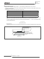
2.1.5. Brazing work
The most important work in the refrigerant piping installation work is the brazing of the pipes. If it accidentally occurs a
leakage due to a careless brazing process, it will cause clogged capillary pipes or serious compressor failure.
In order to guarantee a proper brazing neck between different pipes surfaces, accurate pipe dimensions after the expansion
process (see the table below):
It is important to control the clearance of the pipe fitting portion as shown below. In the case that a cooper tube expansion jig
is used, following dimensions should be secured.
Ød1
+0.08
a
Copper
pipe size
Ød1
+0.09
Gap
+0.1
0.33
-0.08
0
0.07
-0.09
0
0.11
+0.08
+0.1
0.35
+0.12
+0.1
0.42
0
0.09
0
0.08
+0.1
0.38
+0.1
0.42
Ø6.5
Ø9.7
-0.08
+0.08
Ø12.7
6
Ø12.9
8
Ø22.22
Ø22.42
Ø25.4
+0.12
Ø28.58
12
Ø28.78
12
-0.08
0
0.19
-0.12
0
0.08
+0.09
+0.1
0.41
+0.12
+0.1
0.47
0
0.13
0
0.13
+0.1
0.44
+0.1
0.52
0
0.18
Ø15.88
Ø16.1
-0.09
+0.09
Ø19.05
8
Ø19.3
-0.09
Ø32.0
-0.12
+0.12
10
0
Ø31.75
0.16
Ø38.1
a
12
Ø38.3
-0.12
2
10
Ø25.6
-0.12
8
a
0.39
+0.1
Ø6.35
Ø9.53
Gap
d1
Copper
pipe size
14
A basic brazing method is shown below.
Pre-heat the outer tube for better flowing of the filler metal
Heat inner side tube evenly
Rubber plug
Packless valve
High pressure hose
0.03 to 0.05 MPa (0.3 to 0.5 Kg/cm2 G)
Reducer valve: open this valve only when the gas is needed
Nitrogen gas flow 0.05m3/h or smaller
caution
-Use nitrogen gas for blowing during pipe brazing. If oxygen, acetylene or fluorocarbon gas is used, it will cause
an explosion or poisonous gas.
-During the brazing work, a lot of oxidation film will be generated inside of the pipes if no oxygen-free nitrogen
gas is blown through the pipes. This film will be flecked off after operation and will circulate in the refrigeration
cycle, resulting in clogged expansion valves, etc. This coud origin problems in the compressor.
-Use a reducer valve when nitrogen gas blowing is performed during brazing. The gas pressure should be
maintained within 0.03 to 0.05 MPa. If an excessively high pressure is applied to a pipe, it could origin an
explosion.
SMGB0059 rev.0 - 04/2009
17
Electrical wiriing
Service Manual
3. Electrical wiring
Contents
3. Electrical wiring_____________________________________________________________ 19
3.1. General check_ ___________________________________________________________ 20
3.2. Electrical wiring for the outdoor unit____________________________________________ 21
3.2.1.Electrical wiring connection for outdoor unit____________________________________________ 21
3.2.2. Setting the DIP switches for the outdoor unit__________________________________________ 22
3.3. Common wiring_ __________________________________________________________ 25
3.3.1. Electrical wiring between the indoor unit and the outdoor unit_____________________________ 25
3.4. Wire size_ _______________________________________________________________ 27
SMGB0059 rev.0 - 04/2009
19
3
Electrical wiring
Service Manual
3.1.General check
%
danger
-Before installing the electrical wiring or before performing a periodical check, turn OFF the main switch to
the indoor unit and the outdoor unit. For safety reasons, be sure that the indoor fan and the outdoor fan have
stopped.
-Prevent the wires from touching the refrigerant pipes, the plate or cutting edges and the electrical components
inside the unit, to prevent them getting damaged. In worst cases, a fire may occur.
- Tightly secure the wires with the cord clamp inside the indoor unit.
Note
-In case of performing a test run operation take especially care because some security features are disabled: the
units will operate during 2 hours without Thermo-OFF, and the 3-minute guard for compressor protection will not
be effective during the test.
-Fix rubber bushes with an adhesive on the panel when the conduit pipes to the outdoor unit are not used.
-In forced stopped compressor mode, the compressor operation is OFF.
1. Make sure that the field-selected electrical components (main switches, circuit breakers, wires, conduit connectors and
wire terminals) have been properly selected according to the electrical specifications in this service manual. Make sure
that the electrical components comply with the National Electrical Code (NEC).
2. Following the Council Directive 89/336/EEC and its amendments 92/31/EEC and 93/68/EEC, relating to electromagnetic
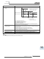
compatibility, next table indicates maximum permissible system impedance Zmax at the interface point of the user’s
supply, in accordance with EN61000-3-11
MODEL
Zmax (Ω)
RAS-8FSN2
RAS-10FSN2
RAS-12FSN2
3. Make sure that the power supply voltage is within ±10% of the rated voltage.
4. Check the capacity of the electrical wires. If the power source capacity is too low, you cannot start the system due to the
voltage drop.
5. Make sure that the ground wire is connected.
6. Main Switch
Install a multi-pole main switch with a distance of 3.5 mm or more between each phase.
20
SMGB0059 rev.0 - 04/2009
Electrical wiriing
Service Manual
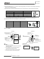
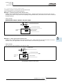
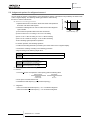
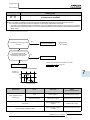
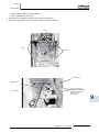
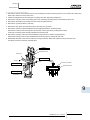
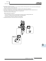
3.2.Electrical wiring for the outdoor unit
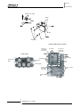
3.2.1.Electrical wiring connection for outdoor unit
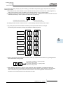
nFSNM(E)
The electrical wiring connection for the outdoor unit is
shown beside.
1. Connect the power supply wires to L1, L2, L3 and N
(for 400V\50Hz) for the three-phase power source on
the terminal board. Connect the ground wires to the
terminals in the electrical box.
2. Connect the control cables between the outdoor unit
and the indoor unit to the terminals 1 and 2 on the
terminal board.
3. Do not run the wires in front of the fixing screw of
the service access panel. If you do so, you cannot
remove the fixing screw.
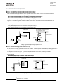
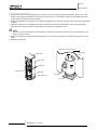
Keep a distance between each wiring terminal and attach insulation tape or sleeve
as shown in the figure.
Correct
Power supply
AC 400V
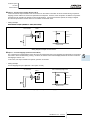
Wiring method with clamp:
Rear cover
1. Insert the wires by into
the cord clamp and clamp
them as shown in the
figure.
2. Perform wiring so that
wires do not touch the
compresor, refrigerant
pipes or edge of the
covers.
Incorrect
Insulation tape or sleeve.
Control
cable
Earth
wire
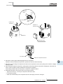
Make a loop of the wires so that disconnecting
the wirings for replacing parts is not required.
Do not use a solderless terminal
when a single wire is used.
If used it causes abnormal heating at
the caulking portion of the terminal.
If a single wire is used connect the
wire direct as shown in the figure.
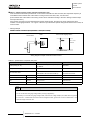
CAUTION:
When using conduit, do NOT lead it in the outdoor unit. If
the conduit wiring touches the compressor and refrigerant cycle in the outdoor unit, it may cause to damage
them.
Power supply
cable
Earth wire
Control cable
Piping cover
Rubber bush
(Accessory)
Power supply cable
&
Conduit
CAUTION
Fix the shielded operation wires between the indoor unit and outdoor unit with a cord band at only one point. You
must connect the shielded operation wires to the earth of the indoor unit only.
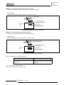
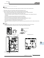
4. Before turning ON the main switch, check the item below.
If the nominal voltage for the outdoor unit is 415V, change
the connector CN4 to CN5 of the transformer TF in the
electrical box as shown in the figure below.
Connector for 220V
Connector for 240V
SMGB0059 rev.0 - 04/2009
21
3
Electrical wiring
Service Manual
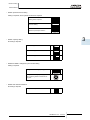
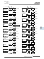
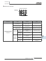
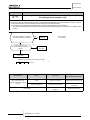
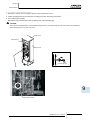
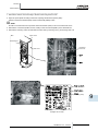
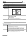
3.2.2. Setting the DIP switches for the outdoor unit
Quantity and location of DIP switches
Push switch PSW1: manual defrost
Push switches PSW2, PSW3: Ckecking by 7-segment
?
NOTE
The mark “■” indicates position of dips switches. Figures show setting before shipment or after selection.
Not mark “■” indicates pin position is not affecting
&
CAUTION
Before setting dips switches, firstly turn off power source and set the position of the dips switches. If the switches
are set without turning off the power source, the contents of the setting are invalid.
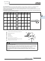
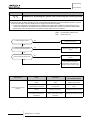
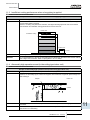
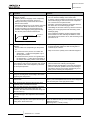
Dip switches setting
– DSW1: Test operation and service setting 1
Setting is required, for test operation and operating the compressor)
DSW1
Setting before shipment
Test cooling operation
Test heating operation
Compressor forced stop
Number 3 pin should be remained at OFF position
22
SMGB0059 rev.0 - 04/2009
Electrical wiriing
Service Manual
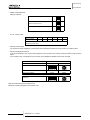
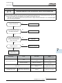
– DSW2: Optional function setting
Setting is required, when optional functions are required
Setting before shipment
Function setting
External input/output selection
3
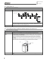
– DSW3: Capacity setting
No setting is required
RAS-8FSNM(E)
RAS-10FSNM(E)
RAS-12FSNM(E)
– DSW4 and RSW1: Refrigerant cycle number setting
Setting is required.
Setting for the tenth digit (first digit)
Seting for the units digit (last digit)
Set by inserting slotted screwdriver into
the grove
– DSW5: End terminal resistance
No setting is required
Setting before shipment
SMGB0059 rev.0 - 04/2009
23
Electrical wiring
Service Manual
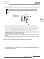
– DSW6: Height difference
Setting is required
Setting before shipment
The indoor unit is located higher than
outdoor unit (20 to 30 m)
Fine-tuning of heating capacity
– JP1~6: Jumper cable
Power supply
380-415V 50Hz
JP1
JP2
JP3
JP4
JP5
JP6
X
X
: with jumper cable
X: without jumper cable
– Setting for transmitting
It is required to set the refrigerant cycle numbers and end terminal resistance for this H-LINK or H-LINKII system.
– Setting of Refrigerant Cycle No.
In the same refrigerant cycle, set the same refrigerant cycle number for the outdoor unit and the indoor units as shown
below.
As for setting indoor unit refrigerant cycle number, set the RSW2 and DSW5 on the indoor unit PCB.
Setting switch
ten digit
unit digit
Outdoor unit
DSW4
RSW1
Indoor unit (H-LINK II)
DSW5
RSW2
Example in case of setting refrigerant cycle
number 25
DSW and RSW setting before shipment is 0.
Maximum in setting refrigerant cycle number is 63
24
SMGB0059 rev.0 - 04/2009
Electrical wiriing
Service Manual
3.3.Common wiring
3.3.1. Electrical wiring between the indoor unit and the outdoor unit
&
CAUTION
Use the shielded twisted pair cable or the shielded pair cable for the transmission cables between the indoor unit
and the outdoor unit. Connect the shielded part to the earth screw in the electrical box of the indoor unit as shown
below. Also use these cables for the operation wiring between one indoor unit and another indoor unit (H-LINK
connection).
Shielded part
Transmission cables
Power supply cables
Earth screw
3
– Connect the electrical cables between the indoor unit and the outdoor unit as shown in the wiring diagram.
– Make sure that the terminals for the power supply wiring and the terminals for the intermediate wires between the
indoor unit and the outdoor unit coincide correctly. The terminals for the power supply wiring are “L1” to “L1”, “L2” to
“L2”, “L3” to “L3” and “N” to “N” of each terminal board. For the operating line, the terminals for the intermediate wires
are “1 and 2” to “1 and 2” of each terminal board for DC 5V. Otherwise, you may damage some components.
– When you are installing the electrical wiring, follow the local codes and the local regulations.
– Connect the operation wiring to the units in the same refrigerant cycle. (You should connect the refrigerant piping and
the control wiring to the same indoor units). If you connect the refrigerant piping and the control wiring to the units in
the different refrigerant cycle, an abnormal operation may occur.
– You must connect the shielded part to earth only in one cable side.
– Do not use more than three cores for the operation wiring (H-LINK II). Select the core sizes according to the national
regulations.
– If there are multiple outdoor units that are connected to one power supply wire, open a hole near the connection hole
for the power supply wiring.
The recommended breaker sizes are shown in the table of electrical data and recommended wiring.
– If a conduit tube for the field wiring is not used, fix the rubber bushes on the panel with adhesive.
– All the field wiring and the equipment must comply with the local codes and the international codes.
– Make sure that the power source voltage is correct.
– An incorrect wiring may cause a breakdown of the transformer PSC-5HR or the units
– Especially, DO NOT connect the power source to the terminal board for transmission.
– DO NOT install the H-LINK II wires along the power supply wire, other signal wires, and others. If you install the
H-LINK II wires along those wires, there may be a malfunction due to the electrical noise. If you need to install the
H-LINK II wires near those wires, provide a distance of 15cm or more. Or alternatively, insert the wires into the steel
pipe and ground one end of the pipe.
SMGB0059 rev.0 - 04/2009
25
Electrical wiring
Service Manual
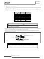
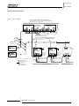
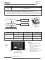
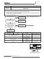
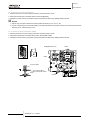
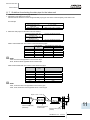
Electrical wiring connection
Models: RAS-8~12FSNM(E)
Models: RAS-8~-48FSN2
Max. 1 Outdoor Unit / Power Supply Line
TheMax.
Power 4
source
must be
made
Unitsfor/ outdoor
Powerunits
Supply
Line
(8individually.
to 12HP)
If not, fire may occur in the worst case.
1 Outdoor Unit / Power Supply Line (14 to 48HP)
No.0 system
outdoor unit
No.2 system
outdoor unit
No.1 system
outdoor unit
Operating line
(shielded twisted pair cable)
DC5V (non-pole transmission, H‑LINK II system)
ELB
Distribution box or pull box
FUSE
Distribution box or pull box
Main switch
No. 0 Indoor unit
No. 1 Indoor unit
Remote control
switch cable
(shielded twist
pair cable)
Remote control
switch (PC-ART)
Remote control
switch cable
(shielded twist
pair cable)
Remote control
switch (PC-ART)
Terminal board
Printed circuit board
Field wiring
Field-supplied
Optional accessory
26
SMGB0059 rev.0 - 04/2009
No. 0 system indoor units
No.1 system indoor units
Electrical wiriing
Service Manual
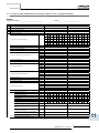
3.4.wire size
nElectrical wiring connection. Field minimum wire sizes for power source.
-- Indoor units
Model
All indoor units
RPI-(8.0/10.0)FSN2E
Power Source
1~230V/50Hz
Power Source Cable Size
Maximum
Current (A)
EN60 335-1
5.0
0.75 mm2
10.0
1.5 mm2
Transmitting Cable Size
Shielded Twist Pair
Cable
MLFC
EN60 335-1
0.75 mm2
0.75mm2
0.5mm2
-- Outdoor units
Model
RAS-8FSN2
RAS-10FSN2
RAS-12FSN2
Power Source Cable Size
Power Source
Maximum
Current (A)
EN60 335-1
MLFC
3~380-415V/50Hz
14.0
18.0
23.0
2.5 mm2
4.0 mm2
4.0 mm2
2.0 mm2
3.5 mm2
3.5 mm2
Transmitting Cable Size
Shielded Twist Pair
EN60 335-1
Cable
0.75mm2
0.75mm2
Refer the notes for selection of the power source cable size in next page
NOTES:
1.Follow local codes and regulations when selecting field wires.
2.The wire sizes marked with in the table of this page are selected at the maximum current of the unit according to
the European Standard, EN60 335-1. Use the wires which are not lighter than the ordinary tough rubber sheathed
flexible cord (code designation H05RN-F) or ordinary polychloroprene sheathed flexible cord (code designation
H05RN-F).
3.The wire sizes marked with in the table of this page are selected at the maximum current of the unit according to
the wire, MLFC (Flame Retardant Polyflex Wire) manufactured by Hitachi Cable Ltd., Japan.
4.Use a shielded cable for the transmitting circuit and connect it to ground.
5.In the case that power cables are connected in series, add each unit maximum current and select wires below.
6.The earth cable size complied with local code: IEC 245, Nº 571.
SMGB0059 rev.0 - 04/2009
27
3
Electrical wiring
Service Manual
Selection according to
EN60 335-1
Current i (A)
Selection according to MLFC
(at cable temp. of 60 ºC)
Wire Size (mm²)
Current i (A)
Wire Size (mm²)
I≤6
0.75
I ≤ 15
0.5
6 < i ≤ 10
1
15 < i ≤ 18
0.75
10 < i ≤ 16
1.5
18 < i ≤ 24
1.25
16 < i ≤ 25
2.5
24 < i ≤ 34
2
25 < i ≤ 32
4
34 < i ≤ 47
3.5
32 < i ≤ 40
6
47 < i ≤ 62
5.5
40 < i ≤ 63
10
62 < i ≤ 78
8
78 < i ≤ 112
14
112 < i ≤ 147
22
63 < i
In the case that current exceeds 63A, use MLFC cables, and do
not connect cables in series.
CAUTION:
-- Install a multi-pole main switch with a space of 3.5 mm or more between each phase.
-- Use shielded wires for transmission wires between the indoor and the outdoor units, and connect the shielded part to
the earth screw in the electrical box of the indoor unit as shown below.
Shield part
Transmission
wires
Power Supply
Wires
Earth screw
nSelect the Main Switches in accordance with the following table:
-- Indoor units
Model
Maximum Running Current
(A)
CB(A)
5.0
6
10.0
16
Power Source
Maximum Running Current
(A)
CB(A)
ELB
no. poles/A/mA
3~380-415V/50Hz
14.0
18.0
23.0
20
30
30
4/20/30
4/30/30
4/30/30
Power Source
All indoor units
1~230V/50Hz
RPI-(8.0/10.0)FSN2E
ELB
no. poles/A/mA
2/40/30
-- Outdoor units
Model
RAS-8FSNM
RAS-10FSNM
RAS-12FSNM
ELB: Earthleakage Breaker; CB: Circuit Breaker
28
SMGB0059 rev.0 - 04/2009
Control system
Service Manual
4. Control system
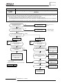
This chapter presents the control system flowcharts for the Set-FREE FSNM(E) Outdoor Units series
Contents
4. Control system_ ____________________________________________________________ 29
4.1. Device control system_ _____________________________________________________ 30
4.1.1. RAS-8~10FSNM(E) refrigerant cycle control__________________________________________ 30
4.2.
Outdoor Units PCB_________________________________________________________________ 32
4.2.1. RAS-8~12FSNM(E)_____________________________________________________________ 32
4
SMGB0059 rev.0 - 04/2009
29
Control system
Service Manual
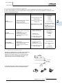
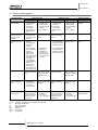
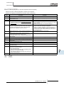
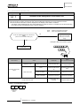
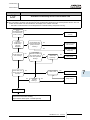
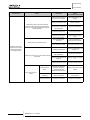
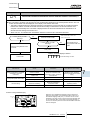
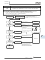
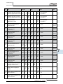
4.1.Device control system
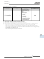
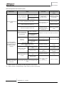
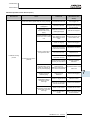
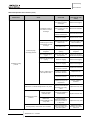
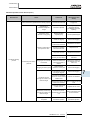
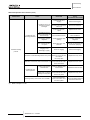
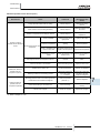
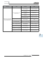
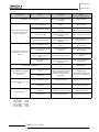
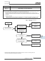
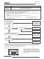
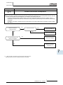
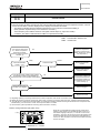
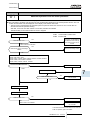
4.1.1. RAS-8~10FSNM(E) refrigerant cycle control
Control subject
Inverter frequency of
the compressor
Opening degree of
expansion valve for
the outdoor heat
exchanger
Opening degree of
expansion valve for
indoor
Outdoor fan
Cooling process
Purpose
Contents
1. Total operation
1. 8Hz/I.U. HP
capacity of the
2. 10 Hz/I.U.HP
indoor unit
(setting DSW6
2. Connection
for piping length
setting)
according to
piping length
3. Pd ≥ 1,0MPa
3. Discharge Pre.
Pd
1. Capacity control Fully open (unused
2. Changeover of
heat exchanger: fully
total indoor unit
close)
capacity
1. For controlling
1. Tdo=Tc+30≤95
temp. of
discharge gas
super-heat
(TdSH)
2. For controlling
2. Temperature
the temperature
difference
difference
between the
between the
gas pipe and
gas pipe and
the liquid pipe of
the liquid pipe of
each indoor unit
the indoor heat
= 4 deg
exchanger
3. For balancing
the temperature
differences
between the
gas pipe and
the liquid pipe of
each indoor unit
Fan controlling
2,5≤Pd≤2,9MPa
discharge pressure
PWM control by DC
(Pd)
motor + constant
speed fan motor
Heating process
Purpose
Contents
1. Total operation
1. 8Hz/I.U. HP
capacity of the
2. 10 Hz/I.U.HP
indoor unit
(setting DSW6
2. Connection
for piping length
according to
setting)
piping length
3. Pd ≥ 1,0MPa
3. Pd
Defrost operation
Contents
All compressors are
operated
Discharge gas
super-heat (TdSH)
control
Fully open
Td0 = Tc + 30 ≤ 90
1. For controlling
Air outlet temp. - air
temp. difference inlet temp. ≤ 24 ºC
between air outlet
and air inlet of I.U
Opening degree is
fixed
2. For balancing the
temp. difference
between air outlet
and air inlet of I.U
Fan controlling
outdoor air temp.
Outdor air temp.
Stop
PWM control by DC
fan motor + constant
speed fan motor
Solenoid valve
equalized pressure
(SVA)
1. For equalizing
the pressure
of the inverter
compressor
during the stop
In case of stopping
inverter comp. after
operation
For controlling inner
pressure of stopag
comp.
In case of stopping
inverter comp. after
operation
Solenoid valve for the
oil return (SVF)
For controlling
temp. oil circulation
volume from the oil
separator to each
compressor
1. Turn ON in comp.
operation
2. Turn OFF in
comp. stoppage
For controlling
temp. oil circulation
volume from the oil
separator to each
compresso
1. Turn ON in comp. Same as cooling/
operation
heating operation
2. Turn OFF in
comp. stoppage
I.U.: Tc / Te:
Td:
Tl: Tg:
Cap:
Temp.:
comp.:
Indoor Unit
Condensing Temperature / Evaporating Temperature
Discharge Temperature
Liquid Temperature
Gas Temperature
Capacity
Temperature
Compresror
30
SMGB0059 rev.0 - 04/2009
–
Control system
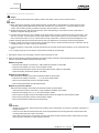
Service Manual
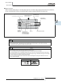
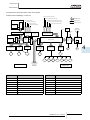
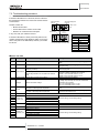
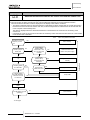
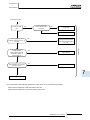
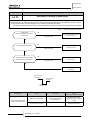
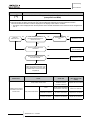
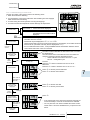
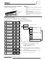
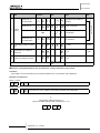
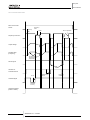
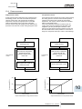
The figure below shows the outline of the control system
Example: RAS-10FSNM(E) + Indoor unit
Suction gas pressure sensor (PS)
Multiple signals
Discharge gas pressure sensor (Pd)
Wireless remote control switch
Thermistor for inlet air
Transmission
circuit
Remote control MCU
Single signals
Thermistor for ambient temperature (THM7)
Thermistor of discharge air
Therm. for heating evap. temp. (THM18)
Thermistor for gas pipe
Thermistor for liquid pipe
Operation signals
Discharge gas thermistor (THM8)
380/415V
Power source
Protection
circuit
Wireless transmission circuit
A+D conversion
circuit
Protection
circuit
Fin thermistor
THM
A+D conversion circuit
Electrical control
expansion valve drive
circuit
MV
Relay drive
circuit
MS
Transmission
circuit
Indoor unit
MCU
Transmission
circuit
Remote control MCU
Transmission
circuit
Remote control switch
Outdoor unit MCU
Electrical control
expansion valve
drive circuit
Thyristor
control circuit
MIF
Relay drive circuit
Inverter
control for fan
MCU
CTu, v
CMC
1
MOF
2
RVR
To the transmission
of the next indoor
unit or the next
outdoor unit
(H-Link I, II)
SVA
SVF
PSH
Outdoor unit
Symbol
Name
Symbol
Name
MC1
DC Motor (for Inverter Compressor)
SVA
Solenoid Valve
MOF1
DC Motor (for Outdoor Fan)
SVF
Solenoid Valve
MOF2,
AC Motor (for Outdoor Fan)
RVR
Reversing Valve
MIF
Motor (for Indoor Fan)
PSH
High Pressure Switch
MS
Motor (for Auto-Louver)
Ps
Suction Gas Pressure Sensor
MV
Electronic Expansion Valve (for Indoor Unit)
Pd
Discharge Gas Pressure Sensor
MV1
Electronic Expansion Valve (for Outdoor Unit)
CTu, v
Current Sensor
CMC1
Magnetic Contactor for Compressor
CH
Crankcase Heater
SMGB0059 rev.0 - 04/2009
31
Inverter power
section
MC1
MOF
1
MV
1
CH
Indoor unit
Inverter
control
MCU
4
Control system
Service Manual
4.2.Outdoor Units PCB
4.2.1. RAS-8~12FSNM(E)
PCB drawing
LED INDICATION
14
15
16
No.
1
Part
Name
DSW1
Contents of functions
• Test running for cooling or heating. The outdoor
unit can be run for testing. When testing has been
finished, reset the function.
• Forced stoppage of compressor. When performing
test running or inspection, compressors can be
forcedly stopped to ensure safety.
2
DSW2
Setting of optional functions
3
DSW3
Setting of capacity code
4
DSW4 and Setting of outdoor unit number
RSW1
5
DSW5
Setting of transmitting
32
SMGB0059 rev.0 - 04/2009
No.
Part
Name
LED1
(Red)
Power Source for PCB1 Normal
Condition: Activated Abnormal
Condition: Deactivated
LED2
(Green)
This LED2 indicates the
transmission state between
the PCB1 and PCB2. Normal
Condition: Flickering Abnormal
Condition: Activated or
Deactivated
LED3
(Yellow)
This LED3 indicates the
transmission state between the
indoor unit and outdoor unit.
Normal Condition: Flickering
Abnormal Condition: Activated or
Deactivated
Contents of functions
6
DSW6
Setting of height difference
7
PSW1
• Manual defrosting switch. The defrosting operation is
manually available under the forced defrosting area.
8
PSW2
• Checking switch push PSW2 for 3 seconds or more,
to start/finish the check mode. Push PSW2, check
mode function is indicated to forward.
9
PSW3
• Checking switch push PSW3, check mode function is
indicated to backward.
13
SEG1
SEG2
These indicate the following: "alarm", "protective safety
device has tripped" or "checking items".
Available optional
functions
Service Manual
5. Available optional functions
Contents
5. Available optional functions____________________________________________________ 33
5.1.
Outdoor units_ ____________________________________________________________________ 34
5.1.1.
5.1.2.
5.1.3.
5.1.4.
Setting of external input and output functions_ ________________________________________
Description of external input signals_________________________________________________
Description of external output signals_ ______________________________________________
Optional functions_______________________________________________________________
34
36
39
41
5
SMGB0059 rev.0 - 04/2009
33
Available optional
functions
Service Manual
5.1.Outdoor units
5.1.1. Setting of external input and output functions
On the outdoor unit printed circuit board, there are three input terminals to receive external signals and two output terminals
to send signals outwards. These signals are available by setting as shown below.
Control Function No. (SEG1)
Input
Output
1
Fixing Heating Operation Mode
Operation Signal
2
Fixing Cooling Opeation Mode
Alarm Signal
3
Demand Stoppage
Compressor ON Signal
4
Snow Sensor (Outdoor fan ON/OFF)
Defrosting Signal
5
Forced Stoppage
--
6
Demand Current Control 60%
--
7
Demand Current Control 70%
--
8
Demand Current Control 80%
--
9
Demand Current Control 100%
--
Each input terminal and output terminal setting as shown below.
Input/Output Terminal Indication
Connector
Setting Function
(SEG2)
(Pin No.)
(Control Function No.)
Input 1
CN17 (1-2)
Fixed Heating Operation Mode (1) *
Input 2
CN17
(2-3)
CN1 (1-2)
Fixed Cooling Operation Mode (2) *
Input 3
CN18
(1-2)
CN1 (2-3)
Demand Stoppage (3) *
CN2 (1-2)
Snow Sensor (Outdoor fan ON/OFF) (4)
Forced Stoppage (5)
Demand Current Control (6 to 9)
Output 1
CN16 (1-2)
Operation Signal (1) *
Output 2
CN16
(1-3)
CN7 (1-2)
Alarm Signal (2) *
CN7 (1-3)
Compressor ON Signal (3)
Defrosting Signal (4)
*: Setting before Shipment
34
SMGB0059 rev.0 - 04/2009
Available optional
functions
Service Manual
In the case that the setting change (only with the mark (*) of the table in the previous page) is required at site, perform the
following procedures.
1 Set DSW2-#6 of the outdoor PCB at the “ON” side while the main power to the outdoor unit is being supplied. By
1 Set
DSW5-#7
of selection
the outdoor
PCB
the “ON”
side
the main
power
the7-segment
outdoor unit
is being supplied. By
setting,
function
mode
is at
available
and
thewhile
following
appears
ontothe
display.
setting, function selection mode is available and the following appears on the 7-segment display.
(The setting should be performed during the outdoor unit stoppage. Also, set DSW1-#4 of outdoor unit PCB at the “ON”
side before performing in order to prevent the malfunction of compressor.)
SEG1
Input/Output Terminal Indication
SEG2
Control Function No.
This display indicates that the control function No. 1 (Fixed Heating Operation Mode) is set at input 1.
2 By pressing the push-switches PSW2 and PSW3, input/output terminal indication is changed.
The following shows the display changes when PSW2 and PSW3 are pushed.
Input terminal
indication 1
Input terminal
5
indication 2
Input terminal
indication 3
Output terminal
indication 1
Output terminal
indication 2
3 After the input/output terminal indication is selected, select your required control function No. by pushing PSW2 or
PSW3 while PSW1 is being pushed.
This number is increased by 1 by pushing PSW2
while PSW1 is being pushed.
This number is decreased by 1 by pushing PSW3
while PSW1 is being pushed.
6 pin at the “OFF” side on the DSW5.
DSW2. The selected contents are
4 After selecting the function No., return No. 7
memorized in the outdoor unit printed circuit board and the function selection mode is stopped. The memorized
data is maintained even power source lines are disconnected. The connecting details of each function are
table.“Seting of external input and output functions”.
described, and the required parts are also indicated in the table
SMGB0059 rev.0 - 04/2009
35
Available optional
functions
Service Manual
5.1.2. Description of external input signals
nInput 1 – Fixing heating operation mode (Control function No.1),
nInput 2 – Fixing cooling operation mode (Control function No.2)
In the case that the fixing input terminals of the operation mode on the outdoor unit PCB1 are short-circuited, the
operation mode can be fixed at the cooling or heating mode.
Short-circuit between Terminals 1 and 2 of CN17:
Fixed
Heating
Operation
Mode
CN1:Fixed
Heating
Operation
Mode
Short-circuit between Terminals 2 and 3 of CN17:
Fixed
Cooling
Operation
Mode
CN1:Fixed
Cooling
Operation
Mode
During this fixed heating (or cooling) mode, no cooling (or heating) operation is available. The indoor units under the
cooling or dry operation (or heating operation) will be changed to the Thermo-OFF condition during this mode, and
stoppage code No. “20” is given.
– Setting Example
Fixing
Fixing Heating
Heating Operation
Operation at
at Input
Input 1
1 (between
(between 1
1 and
and 2
2 pins
pins of
of CN17)
CN1)
Fixing
Fixing Cooling
Cooling Operation
Operation at
at Input
Input 2
2 (between
(between 3
3 and
and 2
2 pins
pins of
of CN17)
CN1)
3P Connector
Outdoor unit
PCB1
SS3: Operation mode fixing switch
SS2: Changeover switch
CN1
Power source
(Heat)
(Cool)
(Cool)
(Heat)
Control circuit
Wiring diagram example of fixing operation mode
nInput 3 – Demand stoppage (Control function No.3)
In the case that the demand input terminals on the outdoor unit PCB1 are short-circuited, compressor(s) is stopped. (In
this case, the indoor unit(s) is put under Thermo-OFF condition. Cooling operation: Air-flow setting, Heating operation: Lo
setting)
The stoppage code No. “10” is given. By disconnecting the demand switch contact, restarting is available.
– Setting Example
Demand Stoppage at Input 3 (between 1 and 2 pins of CN18)
CN2)
3P Connector
Outdoor unit
PCB1
SS3: Demand stoppage switch
CN2
Power source
Control circuit
Wiring diagram example of demand stoppage
36
SMGB0059 rev.0 - 04/2009
Available optional
functions
Service Manual
nInput 3 – Snow sensor (Control function No.4)
In the case that the input terminals of the snow sensor on the outdoor unit PCB1 are short-circuited during compressor
stoppage, all the outdoor fan motors are operated at the full speed. However, if the compressor is called for compressor
operation, the fan operation is changed to the normal operation. If the input terminal is opened, the fan(s) is stopped.
This function protects the outdoor units from a condition covered with snow.
– Setting Example
CN2)
Snow Sensor at Input 3 (between 1 and 2 pins of CN18)
3P Connector
Outdoor unit
PCB1
SS3: Snow sensor switch
CN2
P o w e r
source
Control circuit
Wiring diagram example of snow sensor
nInput 3 – Forced stoppage (Control function No.5)
The compressor is stopped and the indoor fan motor is stopped when the forced stoppage input terminals on the outdoor
unit PCB1 is short-circuited during running. However, the remote control switch display remains at the same mode with
the stoppage code No. “10”.
In this case, if the input terminals are opened, operation is resumed.
– Setting Example
Forced Stoppage at Input 3 (between 1 and 2 pins of CN2)
Forced Stoppage at Input 3 (between 1 and 2 pins of CN18)
3P Connector
Outdoor unit
PCB1
SS3: Forced stoppage switch
CN2
P o w e r
source
Control circuit
Wiring diagram example of forced stoppage
SMGB0059 rev.0 - 04/2009
37
5
Available optional
functions
Service Manual
nInput 3 – Demand current control (Control function No.6 to 9)
In the case that the demand input terminals on the outdoor unit PCB1 are short-circuited, the compressor frequency is
controlled that the maximum limit of the outdoor running current is set 100%, 80%, 70% and 60%.
(The maximum limit of the outdoor unit running current can be selected according to the item “Setting of external input
and output functions”.)
If the outdoor unit running current decreases beyond the maximum limit, the indoor unit is put under thermo-OFF
condition. The stoppage code No. “10” is given. When the input terminal is opened during the demand current control, its
control is reset.
– Setting Example
CN2)
Demand Current Control at Input 3 (between 1 and 2 pins of CN18)
Outdoor unit
PCB1
3P Connector
SS3: Forced stoppage switch
CN2
P o w e r
source
Control circuit
Wiring diagram example of demand current control
Table 5.1 Specifications of required main parts
Parts
Specifications
Mini-Power Relay, MY1F (or 2F) made
Auxiliary Relay (X1, X2)
by OMRON
Changeover Switch (SS2, SS3)
3 Pin Connector Cord
Remarks
220V/240V
Manual Switch
220V/240V
PCC-1A
Five Cords with
(Connected to JST Connector, XARP-3)
Connectors as One Set
lower than 24V
Cord
Low Volt.
0.3mm
(Inside of Unit)
220/240V
0.5 to 0.75mm
Cord
Low Volt.
0.5 to 0.75mm2
(Outside of Unit)
220/240V
2mm
2
2
lower than 24V
2
NOTES
1.Make the wire to the terminals as short as possible.
2.Do not run the wires along high voltage cable. (crossing is applicable.)
If necessary to run wires along high voltage cable, insert the low voltage cable(s) into metal tube and ground
it at one end. If sealed wires are used at the low voltage wire side, ground it at one end of shield wires. The
maximum length should be 70m.
38
SMGB0059 rev.0 - 04/2009
Available optional
functions
Service Manual
5.1.3. Description of external output signals
The following signals can be picked up from the outdoor PCB.
Refer to the table 5.2 for the required main parts.
nOutput 1 – Operating signal (Control function No.1)
Auxiliary relay contacting (RYa) is closed during the operation. Operating signal will be sent when the indoor units are
operating. (Even when one (1) indoor unit is operating, the signal will be sent.) This function can be used for circulator or
humidifier operation.
– Setting Example
Operation Signal at Output 1 (between 1 and 2 pins of CN16)
CN7)
Auxiliary relay
3P Connector housing
Outdoor unit
PCB1
CN16 Connector
CN7 Connector
CN7
Wiring diagram example of operation signal
nOutput 2 – Alarm signal (Control function No.2)
Auxiliary relay contacting (RYa) is closed when the alarm occurs. Alarm signal will be sent when the alarm occurs from
the indoor units. (The signal will be sent even when the alarm occurs from one (1) indoor unit.)
– Setting Example
Alarm Signal at Output 2 (between 1 and 3 pins of CN16)
CN7)
Auxiliary relay
3P Connector housing
Outdoor unit
PCB1
CN7
CN16 Connector
CN7 Connector
Wiring diagram example of alarm signal
SMGB0059 rev.0 - 04/2009
39
5
Available optional
functions
Service Manual
nOutput 2 – Compressor ON signal (Control function No.3)
Auxiliary relay contacting (RYa) is closed during the compressor operation.
– Setting Example
CN7)
Compressor ON Signal at Output 2 (between 1 and 3 pins of CN16)
Auxiliary relay
3P Connector housing
Outdoor unit
PCB1
CN16 Connector
CN7 Connector
CN7
Wiring diagram example of compressor ON signal
nOutput 2 – Defrosting signal (Control function No.4)
Auxiliary relay contacting (RYa) is closed during the defrosting.
– Setting Example
Defrosting Stoppage
Stoppage at
at Output
Output 2
2 (between
(between 1
1 and
and 3
3 pins
pins of
of CN16)
CN7)
Defrosting
Auxiliary relay
3P Connector housing
Outdoor unit
PCB1
CN16
Connector
CN7
Connector
CN7
Wiring diagram example of defrosting signal
Table 5.2 Specifications of required main parts
Parts
Auxiliary Relay *
* Do not use the relay with diode built-in.
* Refer to the table 5.1 for the connector parts.
40
SMGB0059 rev.0 - 04/2009
Specifications
High-Power Relay, LY2F DC12V made
by OMRON
Available optional
functions
Service Manual
5.1.4. Optional functions
↓
Control of the
indoor unit fan during Thermo-OFF in
heating mode
Cancelation of
outdoor ambient
temperature limit of
heating
Cancelation of
outdoor ambient
temperature limit of
cooling
Change of defrost
condicion
Slo defrost setting
Cancellation of outdoor hot start limit
Priority cooling
capacity mode
Priority heating
capacity mode
Not prepared
0
1
0
GH
GC
Jo
bJ
H
cU
hU
SC
↑
↑
SEG2
SEG1
FA
↓
↓
↑
SEG2
Not Available
Not prepared
SEG1
SH
Available
Not Available
1
Available
0
Not Available
1
Available
0
Not Available
1
Available
0
Not Available
1
Available
0
Not Available
1
Available
0
Not Available
1
Available
0
Not Available
1
Available
0
Not Available
1
Available
Long piping setting
Low noise setting
Fixing on demand
function
Wave function setting
Cold draft protection 1
Cold draft protection 2
Not prepared
Not prepared
nH
db
dE
UE
Fb
Fc
Ei
Co
↓
↑
SMGB0059 rev.0 - 04/2009
0
Not Available
1
Available
0
Not Available
1
Available
0
Not Available
1
Available
0
Not Available
1
Available
0
Not Available
1
Available
0
Not Available
1
Available
0
Not Available
1
Available
0
Not Available
1
Available
0
Not Available
1
Available
41
5
Available optional
functions
Service Manual
nCirculator function at heating thermo-OFF
Press “RSW1” and select the setting condition “1” at the circulator function at heating thermo-OFF “
”.
In case that the fan speed is changed to “LOW” at heating Thermo-OFF, there is a case that the room air temperature is
too high at heating Thermo-OFF.
In this case, the circulator function at heating thermo-OFF is recommended, and its function explains below.
The indoor fan operates for 2 minutes and stops for 6 minutes as a cycle when the activation conditions are satisfied.
Operation
When the indoor unit is at thermo-OFF during
the heating operation, the indoor fan operates and
stops for 6 minutes in 2 minute cycles
Start at random
(min)
NOTE
When the indoor fan is stopped by another control, it is not available to operate indoor fans.
nNight-Shift (Low noise)
Press “PSW1” and select the setting condition “1” at the night shift (low noise) “ni“. Then, this function can be set.
The outdoor fan operation is controlled by fan controller as shown below.
The night shift operation shall be applied in case that the cooling capacity has the margin to be allowed for the capacity
decrease and the low sound operation is required especially in the nighttime.
Outdoor Fan
Maximum rotation
(rotation ratio)
Outdoor temperature (ºC)
NOTE
The maximum rotation is always 100% (rotation ratio) for the standard unit. (No limitation of the outdoor
temperature)
42
SMGB0059 rev.0 - 04/2009
Available optional
functions
Service Manual
nFrequency range (Cooling operation)
Outdoor
Unit
Capacity
Minimum Maximum
Outdoor
Unit Capacity
Minimum Frequency
Frequency
Frequency
Conditions
(HP)
(Hz)
8
When night shift is not set
ni=0
8
68
15
8
68
60
10
85
10
85
60
12
12
100
12
100
60
14
119
14
18
136 Capacity
Outdoor Unit
153
(HP)
Minimum Frequency
20
170
8
15
When night shift
22 is set
ni=0
(Hz)
10
16
When
night shift
is not set
(Hz)
(HP)
Outdoor
Minimum Maximum
UnitMaximum Frequency
Frequency Frequency
Capacity
(Hz)
(Hz)
(Hz)
(HP)
ni=1 24
26
28
15
(Hz)
90
20
60
Except for the
conditions on
the right
238
60
24
When
night shift
is set
60
26
15
28
ni=1
Conditions
110
(1) ni=1
(2) Outdoor fan:
Below 70%
122
127
132
(1) ni=1
(2) Outdoor fan:
Below 70%
137
30
255
30
175
32
272
32
187
34
289
34
199
36
304
36
214
38
323
38
244
40
340
40
254
42
357
42
264
44
374
44
271
46
391
46
281
48
408
48
291
5
Converted frequency of constant speed compressor
Power supply frequency (Hz)
Outdoor unit capacity
Conditions
Except for the
conditions on the right
16Maximum Frequency
100
18
105
(Hz)
22
187
10
204
12
221
Conditions
(HP)
MC2
MC3
MC4
MC5
14, 16
50
-
-
-
18, 20
50
50
-
-
22, 24
50
77
-
-
26, 28
77
77
-
-
30~36
77
77
50
-
38~42
77
77
50
77
44~48
77
77
77
77
Note
The maximum frequency for the 8 to 48HP outdoor unit is indicated as;
Inverter frequency + converted frequency of constant speed compressor.
SMGB0059 rev.0 - 04/2009
43
Available optional
functions
Service Manual
nCancellation of outdoor ambient temperature limit of heating
Press “PSW1” and select the setting condition “1” at the cancellation of outdoor ambient temp. limit of heating “
Then, this function can be set.
”.
The heating operation is continued under a high outdoor temperature.
Operation in heating mode
The factory-set limitation of the range
of permissible outdoor temperature in
the heating process, which is shown in
the right figure, is cancelled.
Area of operation
stoppage
Suction air temperature (°C)
Outdoor Temp (°C)
Note
The operation may be OFF due to high outdoor temperature protection control, since protection control is not
cancelled.
nCancellation of outdoor ambient temperature limit of cooling
Press “PSW1” and select the setting condition “1” at the cancellation of outdoor ambient temp. limit of cooling “GC”.
Then, this function can be set.
The cooling operation is continued under a low temperature.
Operation in cooling mode
The factory-set limitation of the range
of permissible outdoor temperature in
the heating process, which is shown in
the right figure, is cancelled.
Area of operation
stoppage
Suction air temperature (°C)
Outdoor Temp (°C)
Note
The operation may be OFF due to low outdoor temperature protection control since protection control is not
cancelled.
44
SMGB0059 rev.0 - 04/2009
Available optional
functions
Service Manual
nChange of defrost condition
Press “PSW1” and select the setting condition “1” at the change of defrost condition “Jo”.
Standard Specifications
Setting condition
When change of defrost condition is NOT set
Cold area specification
When change of defrost condition is set
Temperature
stop area
under defrosting
operation
Defrosting operation
stop area
Defrosting operation
conditions
Outdoor evaporating
temperature (ºC)
(Pipe)
Outdoor evaporating
temperature (ºC)
(Pipe)
Outdoor temperature (ºC)
Outdoor temperature (ºC)
Defrosting operation
start area
Defrosting operation
start area
nSLo defrost setting
Press “PSW1” and select the setting condition “1” at the slow defrost setting “bJ“.
Indoor fan operation is stopped during the defrost operation. However, this function can be operated the indoor fan at low
speed during the defrosting operation.
nLong piping setting
Press “PSW1” and select the setting condition “1” at the long piping setting “nH”.
If cooling capacity or heating capacity is not enough under the long-distance piping condition, this function can be set the
target compressor frequency higher than normal target value.
nLow noise setting
Press “PSW1” and select the setting condition “1”, so the low noise setting “db” can be set.
The outdoor fan maximum rotation is set lower than normal setting regardless of outdoor temperature.
However, continuous operation can not be operated under the condition below.
a)Outdoor temperature is over 40 ºC.
b)Total combination horsepower is over 100%.
SMGB0059 rev.0 - 04/2009
45
5
Available optional
functions
Service Manual
nFixing of demand function
Press “PSW1” and select the setting condition “1”, so that the fixing of demand function “dE” can be set.
However, it is not necessary to short-circuit the demand input terminals on the outdoor unit PCB. (Refer to the item “Input
3 – Demand Current Control”)
The table below is the limit of the running current for this function.
Control Function No. *
Demand Running Current Control
1 to 5
100%
6
60%
7
70%
8
80%
9
100%
* This function can be activated when demand function is selected at one of the input terminal indications i1, i2 and
i3.
In case that multiple demand functions are set at the input terminal indicationsi1, i2 and i3, the demand running
current is selected as below.
6>7>8>9
|
(Control Function No.)
* Demand Control
Adopting self-demand function which drastically decreases power consumption has largely improved energy-saving.
Power consumption
Excesive power supply
consumption exceeding
the power setting range is
restricted
Power setting
Morning
Daytime
Operating hours
46
SMGB0059 rev.0 - 04/2009
Selectable from 100%, 80%,
70% and 60% of the rated
power consumption for cooling
operation
Nigth
Available optional
functions
Service Manual
nWave function setting
Press “PSW1” and select the setting condition “1”, so that the wave function setting “UE”.
While this function is activated, the maximum limit of running current is changed from 60% to 100% as shown in the
figure.
* Wave function cannot be available when the setting condition “1” at the fixing of demand function “dE” is selected
and the demand current control from the external input signal is set.
Electricity
consumption
(100%)
Electricity
consumption
(60 to 100%)
* Wave function can be activated when demand function is selected at one of the input terminal indicationsi1, i2
and i3.
The minimum limit of running current control is according to the set value of the demand function.
If demand function is not set at the input terminal indication, this function can not be activated. n
protection 1
Cold draft
Press PSW1 and select the setting condition “1” at the cold draft protection 1 “Fb”, so the cold draft protection can be set.
When the minimum Indoor unit discharge air temperature falls down to 12 ºC and below at cooling operation, outdoor fan
stops and compressor frequency forcibly decreases to prevent a drop in discharge air temperature.
nCold draft protection 2
Press PSW1 and select the setting condition “1” at the cold draft protection 2 “Fc” , so this function can be set. When
Indoor unit minimum discharge air temperature falls down to 10 ºC and below at cooling operation, the compressor stops.
In this case, stoppage code number “28” is given.
SMGB0059 rev.0 - 04/2009
47
5
Test run
Service Manual
6. Test run
Contents
6. Test run___________________________________________________________________ 49
6.1. Checking procedure before the test run ________________________________________ 50
6.2. Test run procedure from the outdoor unit side____________________________________ 52
6.3. Check list________________________________________________________________ 53
6.4. Judgement system for refrigerant amount_______________________________________ 56
6
SMGB0059 rev.0 - 04/2009
49
Test run
Service Manual
6.1.Checking procedure before the test run
Test run should be performed according to the Table 6.2. And use the Table 6.1 for recording test run .
$ WARNING
nDo not operate the system until all the check points have been cleared .
A)Check to ensure that the refrigerant piping and transmission between outdoor unit and indoor units are connected to
the same refrigerant cycle. If not, it will cause an abnormal operation and a serious accident .
B)Check to ensure that the electrical resistance is more than 1 megohm, by measuring the resistance between ground
and the terminal of the electrical parts. If not, do not operate the system until the electrical leakage is found and
repaired .
C)Check to ensure that the stop valves of the outdoor unit are fully opened, and then start the system .
D)Check to ensure that the switch on the main power source has been ON for more than 12 hours, to warm the
compressor oil by the oil heater .
E)Check that the refrigerant piping and the electrical wiring conform to the same system, and check that the dip switch
setting of the refrigerant cycle No. (DSW1 & RSW1 [O.U.], DSW5 & RSW2 [I.U.]) and the unit number (RSW) for the
indoor units apply to the system .
Confirm that the dip switch setting on the printed circuit board of the indoor units and the outdoor units are correct .
Especially, pay attention to the setting of lift between indoor units and outdoor unit, the refrigerant No. and the end
terminal resistance. Refer to the chapter “6. Electrical Wiring” .
F)Check to ensure that the electrical resistance is more than 1 megohm, by measuring the resistance between ground
and the terminal of the electrical parts. If not, do not operate the system until the electrical leakage is found and
repaired. Do not impress the voltage on the terminals for transmission 1 and 2 .
G)Check to ensure that each wire, L1, L2, L3 and N (R, S and T) is correctly connected at the power source .
If incorrectly connected, the unit will not operate and the remote control switch will indicate the alarm code “05”. In
this case, check and change the phase of the power source according to the attached seat on the reverse side of the
service cover .
H)Check to ensure that switch on the main power source has been ON for more than 12 hours, to warm the compressor
oil by the oil heater .
nFSN2 series outdoor units does not operate within 4 hours after power supply (Stoppage Code d1-22) .
In case of operating within 4 hours, release the protection control as follows:
1. Supply power to the outdoor unit and indoor units .
2. Wait for 30 seconds .
3. Push PSW1 on PCB more than 3 seconds .
nPay attention to the following items while the system is running .
A) Do not touch any of the parts by hand at the discharge gas side, since the compressor chamber and the pipes at
the discharge side are heated higher than 90°C .
B) DO NOT PUSH THE BUTTON OF THE MAGNETIC SWITCH(ES). It will cause a serious accident .
nDo not touch any electrical components for at least 3 minutes after turning OFF the main switch .
nCheck that the refrigerant piping setting and electrical wiring setting are for the same system, by operating the
indoor unit one by
50
SMGB0059 rev.0 - 04/2009
Test run
Service Manual
$CAUTION
nCaution for Insulation Resistance
If total unit insulation resistance is lower than 1 megohm, the compressor insulation resistance may be low due to retained
refrigerant in the compressor. This may occur if the unit has not been used for long periods .
1. Disconnect the cables to the compressor and measure the insulation resistance of the compressor itself. If the
resistance value is over 1 megohm, then insulation failure has occurred of other electrical parts .
2. If the insulation resistance is less than 1 megohm, disconnect the compressor cable from the inverter PCB. Then, turn
on the main power to apply current to the crankcase heater .
After applying current for more than 3 hours, measure insulation resistance again. (Depending on the air conditions,
pipe length or refrigerant conditions, it may be necessary to apply the current for a longer period of time.) Check the
insulation resistance and reconnect the compressor .
If the leakage breaker is activated, check the recommended size shown in Table 6.1 .
? NOTES
1. Confirm that field-supplied electrical components (main switch fuse, fuse-free breaker, earth leakage breakers, wires,
conduit connectors and wire terminals) have been properly selected according to the electrical data given in this
Technical Catalog of the unit and ensure that the components comply with national and local codes .
2. Use shielded wires (≥0.75mm2) for field wiring to protect electrically noise obstacle. (Total length of shielded wire shall
be less then 1000m, and size of shielded wire shall comply with local codes.)
3. Check to ensure that the terminal for power source wiring (terminals “L1” to “L1” and “N” to “N” of each terminal board:
AC 380-415V, terminals “R” to “L1” and “S” to “L2” of each terminal board: AC 220V) .
If not, some component will be damaged .
6
SMGB0059 rev.0 - 04/2009
51
Test run
Service Manual
6.2.Test run procedure from the outdoor unit side
The test run procedure from the outdoor unit side is shown below. You can set this DIP switch while the power source is ON
Setting of Dip Switch (before shipment)
DSW1
1
3
Test run
COOL/HEAT setting
(ON: Heating operation)
(OFF: Cooling operation)
OFF (mixed)
4
Manual compressor OFF
2
Test run
$Warning:
– Do not touch any other electrical components while you
are setting the switches on the PCB.
– Do not attach or detach the service access panel when
the power source for the outdoor unit is ON and the
outdoor unit is operating.
– Set all the DIP switches of DSW1 to OFF after completing
the test run.
Dip switch seting
Operation
Remarks
1. Setting operation mode
Cooling: Set DSW1-2 OFF
– The indoor unit automatically
starts to operate when the
test run of the outdoor unit is
set.
– You can perform the ON/OFF
operation from the remote
control switch or the DSW1-1
of the outdoor unit.
– Continuous operation during
2 hours is performed without
the Thermo-OFF condition.
– Make sure that the indoor units start to operate
in accord with the test run of the outdoor unit.
– If you start the test run from the outdoor unit
and you stop the test run from the remote
control switch, the test run function of the
remote control switch is cancelled. However,
the test run function of the outdoor unit is not
cancelled. Check to ensure that the DSW1-1 of
the outdoor unit PCB is turned OFF
– In case that more than one indoor units are
connected with one remote control switch,
perform the test run operation at each
refrigerant system one by one. Then, make
sure to turn the power source OFF for the
indoor units at other refrigerant system not to
operate test run.
Heating: SET DSW1-2 ON
Starting the test run:
Set DSW1-1 at ON. The
operation starts after 20 s.
In case of heating process, leave
DSW1-2 at ON
Outdoor unit
Test run
Manual
compressor
OFF
Setting the compressor manually
OFF: Set DSW1-4 at ON
ON: Set DSW1-4 at OFF
–
–
Manual defrost – Manual defrost operation
–
starts. Press the PSW1 for
more than three seconds
during the heating process.
The defrost operation starts
after two minutes. This
–
function is available once the
heating process has been
running for five minutes.
– Manual defrost operation
finishes. The defrost operation
automatically finishes and the
heating process starts.
52
SMGB0059 rev.0 - 04/2009
Power OFF
– The setting of DSW1 is not required for the test
run from the remote control switch.
When DSW1-4 is ON during
– Do not turn ON and OFF the compressor
the compressor operation, the
frequently
compressor stops operating
immediately and the indoor
unit is under the Thermo-OFF
condition.
When DSW1-4 is OFF, the
compressor starts to operate
after the cancellation of the
3-minute guard.
The defrost operation is
– Do not repeat the defrost operation frequently.
available regardless of the
– When the PSW1 accepts the manual defrost
frosting conditions and the
operation, the remaining time before starting
total time of the heating
the defrost operation is displayed at the
process.
7-segment display on the PCB.
The defrost operation is
d 20
not performed when the
temperature of the outdoor
Remaining time (every 4 seconds)
heat exchanger is higher than
10°C, the high pressure is
higher than 2.0 Mpa or under
the Thermo-OFF condition.
Test run
Service Manual
6.3.Check list
nCheck list on test run
Client:
Installer:
Date:
Outdoor unit model:
Outdoor unit serial No.:
Checker:
Indoor unit
model:
Indoor unit
serial No.
Piping lenght [m]
Additional refrigerant
charge [kg]
1. General
No.
Check item
Result
1
Was the DIP switch DSW6 for the piping length in the outdoor unit set?
2
Are the power supply wires of the transmission cable making contacts on the piping?
3
Was a ground wire connected?
4
Is there any short circuit?
5
Is there any voltage malfunction among the different phases (L1-L2, L2-L3, L3-L1, L1-N)?
2. Refrigerant cycle
a. Cooling/heating process
No.
Check item
1
Operate all the indoor units. (TEST RUN mode).
2
Operate all the indoor units at the “HIGH” speed.
Result
b. Sampling data (cooling/heating process: if the indoor temperature is between 21°C and 30°C)
No.
Check item
1
After operating for more than 20 minutes.
2
Check Pd. and Td. Is TdSH 15 to 45 degrees?
3
Is Ps 0.2 to 1.1?
4
Is Pd 1.0 to 3.5?
(If the outdoor temperature is high, the Pd. becomes high.)
Result
SMGB0059 rev.0 - 04/2009
53
6
Test run
Service Manual
3. Check item after sampling data
a. Cooling process (if the outdoor temperature is higher than 15 ºC)
No.
Check item
Standard
1
Is H1 (compressor frequency)
abnormally low or high?
(It is applicable when the inlet air
temperature is three degrees higher
than the setting temperature).
Is the fan actually running when Fo
(airflow rate of fan) is other than "0"?
Running horsepower of the Low: excessive refrigerant;
indoor units X 8Hz.
High: insufficient refrigerant;
DSW for capacity of indoor
units: Incorrect setting.
2
3
4
5
6
7
8
9
Causes
–
Is the total of iE (indoor expansion
Total % of iE:
valves opening) abnormally low or high? horsepower of the outdoor
unit X (0.7 to 1.5).
Is TL (liquid pipe temperature of the
It is normal when
heat exchanger of the indoor unit) lower TL-Ti < -5 deg.
than Ti (air inlet temperature of the
indoor unit)?
Is TG (gas pipe temperature of the heat It is normal when
exchanger of the indoor unit) lower than TG-Ti < -5 deg.
Ti (air inlet temperature of the indoor
unit.)?
Is there any excessive difference
among indoor units at SH(TG-TL)
of the heat exchanger of the indoor
units? (It is applicable when the inlet
air temperature is three degrees higher
than the setting temperature.)
Is there any excessive different among
indoor units at SH (TG-TL) of the heat
exchanger of the indoor units and is iE
lower than 7?
(It is applicable when intake air temp. is
3 deg. higher than setting temp.
Is there any indoor unit with SH (TGTL) excessively lower than the value
of other units, under the condition of IE
(indoor unit expansion valve) 100?
It is normal if the difference
among units is within 3 - 7
deg. lower than other units.
Is the difference between the discharge
air temperature and the inlet air
temperature more than 7 deg.?
* The temperature difference between
I.U. means the following: b3
(Discharge Air Temp.) - b2 (Intake
Air Temp.) indicated on the remote
control switch by check mode.
–
54
It is normal if SH is within 3
deg. lower than other units.
It is normal if SH is within
3 deg. higher than other
units.
SMGB0059 rev.0 - 04/2009
Failure of the fan motor;
Failure of the PCB1;
Failure of the condenser.
Low: excessive refrigerant;
High: insufficient refrigerant,
excessive pipe resistance.
Failure of the TL thermistor;
Fully closed expansion valve;
Short circuit.
Failure of the TG thermistor;
Fully closed expansion valve
or slightly open expansion
valve;
Short circuit.
Failure of the TL/TG
thermistor;
Fully open expansion valve,
slightly open expansion valve
or fully closed expansion
valve.
Expansion valve locked in fully
open position; The refrigerant
cycle number does not match;
Mismatched between wiring
and piping.
Expansion valve locked in
slightly open position or
closed expansion valve; The
refrigerant cycle number
does not match; Mismatched
between wiring and piping.
–
Result
Test run
Service Manual
b. Heating process (if the outdoor temperature is higher than 0 ºC)
No.
Check item
1
Is oE (outdoor unit expansion valves
Total of oE:
opening) abnormally low or high when
total frequency of
TdSH is 15 to 45 degrees?
compressor x 0.2 to 0.6
Is Pd 1.6 to 3.5?
(Pd is high when the indoor temperature
is high).
2
3
4
5
Is H1 (compressor frequency)
abnormally low or high? (The lower
the room temperature and the outdoor
temperature, the higher the above
value).
Is Ps 0.2 to 1.1?
(Only under the condition that the
electrical expansion valve (SVA) is
OFF).
Is the temperature difference among
the indoor units* more than 10 degrees
when iE (indoor unit expansion valve)
is “100”?
*The temperature difference among the
indoor units means the following:
b3 (Discharge Gas Temperature)
- b2 (air inlet temperature) that is
displayed on the remote control
switch by means of the check mode.
However, this is applicable only
when b2 (Air Inlet Temperature) - b1
(setting temperature) is higher than
three degrees.
Standard
Causes
Result
Low: excessive refrigerant;
High: insufficient refrigerant.
Low: leakage of the SVA
(solenoid valve);
High: excessive gas pipe
resistance.
Low: excessive refrigerant;
High: insufficient refrigerant,
excessive pipe resistance.
Low: short circuit of the indoor
unit;
Low/High: failure of the
following components: outdoor
unit fan motor or outdoor
ambient thermistor.
Failure of components such
as the PCB, the wiring, the
coil, the valve;
Excessive pipe resistance;
Failure of the thermistor for
the discharge air temperature.
6
? NOTE:
1. The symbol with an underline indicates a check item. The mark indicates the checking data.
SMGB0059 rev.0 - 04/2009
55
Test run
Service Manual
6.4.Judgement system for refrigerant amount
¡¡ Before the checking procedure:
1. Operate all the indoor units at the TEST RUN mode and operate all
the indoor units at the HIGH speed.
2. Check the following items in order to make sure that the refrigerant
cycle is stable.
1) The continuous operation lasts more than 20 minutes.
Outdoor air temp. (ºC)
You can check the excess or the deficiency of the refrigerant by means of the data that is provided by the check mode
of the 7-segment display. The following checking procedure is useful during
the test run and the maintenance.
Indoor air temp. (ºC)
2) Td·SH is 25 to 45 ºC in cooling or 15 to 45 ºC in heating
3) Ps is 0.4 to 1.1 MPa in cooling or 0.2 to 1.1 MPa in heating
4) Pd is 2.0 to 3.5 MPa in cooling or 1.6 to 3.5 MPa in heating
Td·SH: Discharge gas temperature superheat
Ps: Suction pressure, Pd: Discharge pressure
3. Collect the checking data that is provided by the check mode of the 7-segment display.
4. Perform the checking according to the following procedure.
Judge according to the following target value:
Cooling
Refrigerant flow charge is controlled by indoor unit expansion valve
Heating
Refrigerant flow charge is controlled by outdoor unit expansion valve
Applicable air temperatures for the checking procedure:
Cooling
Room temperature: 20°C~30°C (DB)
Outdoor temperature: 15°C (DB) or more
Heating
Room temperature: 20°C~30°C (DB)
Outdoor temperature: 0°C~15°C (DB)
¡¡ Checking procedures for cooling
Process
1. Convert iE (indoor unit expansion valve opening) with the following table:
Indoor Unit HP
0.8 to 6 HP
8 and 10 HP
Conversion
iE
iE × 2.0
2. Sum up the converted values of iE.
3. Calculate the total frequency (=H1(Inverter frequency))
Judgement
- If total of converted iE/Total frequency < 0.7 = Insufficient refrigerant
- If total of converted iE/Total frequency > 1.6 = Excessive refrigerant
56
SMGB0059 rev.0 - 04/2009
Test run
Service Manual
¡¡ Checking procedures for heating
Process
1. Detect oE (total outdoor unit expansion valve opening)
2. Calculate the total frequency (=H1(Inverter frequency)).
Judgement
- If total oE/Total frequency < 0.8 x Target value = Insufficient refrigerant
- If total oE/Total frequency > 1.2 x Target value = Excessive refrigerant
Target value
Refer to the following table to use the target value in heating.
Outdoor air temp. (ºC)
¡¡ Examples
Cooling process
iE (%) (from the checking data)
Calculate value of iE
2HP
32
32
(Hold)
2HP
38
38
(Hold)
Total of iE (a)
Total frequency (b)
Judgement
Indoor units
2HP
2HP
30
20
30
20
(Hold)
(Hold)
138 (32+38+30+20+18)
90
OK: 0.7 ≤ (a) / (b) ≤ 1.6
2HP
18
18
(Hold)
Heating process
Ti (indoor suction temperature)
To (outdoor temperature) (°C)
Total of oE (a)
Total of frequency (b)
Judgement
2HP
26
2HP
27
Indoor units
2HP
23
2HP
23
Outdoor unit
10HP
–
7
42
2HP
25
–
100
OK: (a) / (b) ≈± 20% of target value
SMGB0059 rev.0 - 04/2009
57
6
Troubleshooting
Service Manual
7. Troubleshooting
Contents
7. Troubleshooting_____________________________________________________________ 59
7.1. Initial troubleshooting_______________________________________________________ 60
7.1.1.
7.1.2.
7.1.3.
7.1.4.
Emergency operation____________________________________________________________
Failure of the power supply to the indoor unit and the remote control switch_ ________________
Abnormal transmission between the remote control switch and the indoor unit_ ______________
Abnormal operation of the devices__________________________________________________
61
62
63
64
7.2. Troubleshooting procedure_ _________________________________________________ 72
7.2.1.
7.2.2.
7.2.3.
7.2.4.
7.2.5.
7.2.6.
7.2.7.
Alarm code indication of remote control switch_ _______________________________________ 72
Troubleshooting by alarm code_ ___________________________________________________ 74
Troubleshooting in check mode___________________________________________________ 115
Troubleshooting by means of the 7 segment display___________________________________ 121
Running current of the compressor_ _______________________________________________ 127
Protection control code on the 7-segment display_____________________________________ 129
Activating condition of the protection control code_____________________________________ 130
7
SMGB0059 rev.0 - 04/2009
59
Troubleshooting
Service Manual
7.1.Initial troubleshooting
Checking by means of the 7-segment display
Simple checking procedure by means of the 7-segment display
1. Turn on all the indoor units which are connected to the outdoor unit.
2. Turn on the outdoor unit
3. Auto-addressing starts. (Outdoor unit printed circuit board PCB 1)
During the auto-addressing, you can check the following items by means of the 7-segment display of the outdoor unit.
– Disconnection of the power supply to the Indoor Unit.
–Duplication of the Indoor Unit number.
Normal case:
The 7-segment display of the outdoor unit is not indicated.
Abnormal case:
If there is something wrong, the 7-segment display of the outdoor unit displays the following indications:
Cause
Indication
a. The indoor units are not supplied
with power.
b. Disconnection of the operating line
between the outdoor units and the
indoor units.
03
continues to flash after 30 seconds.
03
continues to flash after 30 seconds.
c. Duplicated settings of the indoor
unit number on the rotary switch
RSW (Refer to the section
"Troubleshooting by means of the
Alarm Code" for the description of
the alarm code "35").
60
SMGB0059 rev.0 - 04/2009
Remarks
Troubleshooting
Service Manual
7.1.1. Emergency operation
Method of collecting refrigerant (In case that compressor does not operate)
Perform only when collecting refrigerant of outdoor unit is required.
(Perform the replacing compressor and oil return circuit if necessary.)
Process
No.
1
2
3
4
Procedure
Turn OFF the main switch of O.U.
Connect manifold to the check joint* at low and high
pressure sides of O.U.
Close the liquid and gas stop valve completely.
Collecting refrigerant in O.U.)
– Collect the refrigerant from check joint at high and low
pressure sides using the collector.
5
Remove charge hose at the low and high pressure sides
check joint, so that the low pressure side of the refrigerant
cycle will be the atmosphere pressure. Disconnect the
charge hose at charge port of return oil circuit.
6
Perform replacing comp., return oil circuit and electrical
parts.
With the electrical box mounted, check the wrings by
contacting (except the power line for comp.)
For the power line for comp., insulate the wiring terminal
with vinyl tape.
Turn ON the main switch of O.U.
Set DSW4-#4 to ON side (O.U. PCB1).
Perform the vacuuming from the check joint at low and high
pressure side.
Turn OFF the main switch of O.U.
Set DSW1-#4, back to the original setting.
Check that the power line for comp. and wiring are
connected correctly.
Recharge the collected refrigerant (Process No.4) from the
check joint at high pressure side.
For the remained quantity:
Open the liquid and gas stop valve completely and set
DSW4-#1 to ON side (O.U. PCB1).
Then recharge it from the liquid stop valve check joint
during cooling operation.
Check the liquid and gas stop valves are open completely.
7
8
9
10
11
12
13
14
15
O.U.: I.U.: 7-Seg.: Comp.: Remarks
* Not the check joint of liquid/gas stop valves.
To improve the performance of vacuuming.
– The discharge of the refrigerant in the atmosphere is
strictly forbidden. Make sure that the refrigerant is collected
by the collector.
– Measure the quantity of the collected refrigerant
– Make sure that there is no pressure increase of the low
pressure side after collecting the refrigerant.
– Make sure that the refrigerant cycle is the atmosphere
pressure. Otherwise, problems such as the blowing of gas
and the suction of the cutting material may occur when
removing the comp.
Removing electrical box may be required.
This process is before removing and mounting electrical box.
Refer to Process No. 9.
7
Outdoor Unit
Indoor Unit
7-Segment
Compressor
SMGB0059 rev.0 - 04/2009
61
Troubleshooting
Service Manual
7.1.2. Failure of the power supply to the indoor unit and the remote control switch
nThe LED and the LCD are not indicated.
nNot operated
If the fuses are blown out or a breaker is activated, investigate the cause of the overcurrent and take the necessary
action.
Check item
Action
(Turn OFF the main switch)
Measure the voltage by means of
the voltmeter
Supply the power
Short circuit supplied between
the wires
Check for any uncovered part of
the wires
Remove the cause of the short
circuit and replace the fuse
Short circuit of the wires to earth
Measure the insulation
resistance
Remove the cause of the short
circuit and replace the fuse
Failure of indoor unit fan motor
Measure resistance between
wires and insulation resistance
Replace AC chopper for indoor
unit fan, fan motor and fuse
Phenomenon
Cause
Power failure or power is not ON
Blown out fuse or activation of
the breaker at the power source
Failure of AC chopper for indoor
fan
Blown out fuse at the control
circuit
Replace AC chopper for indoor
unit fan and fuse
Short circuit supplied between
the wires
Check for any uncovered part of
the wires
Remove the cause of the short
circuit and replace the fuse
Short circuit of the control circuit
to earth
Measure the insulation
resistance
Remove the cause of the short
circuit and replace the fuse
Failure of indoor unit fan motor
Measure resistance between
wires and insulation resistance
Replace AC chopper for indoor
unit fan, fan motor and fuse
Failure of AC chopper for indoor
fan
Replace AC chopper for indoor
unit fan and fuse
Failure of the transformer at the indoor unit side
Measure the voltage at the
secondary side
Replace the transformer
Disconnected cable of the remote control switch
Connect the cable
Replace the cable or repair the
cable
Check the connectors
Correctly connect the connector
Check the remote control switch
by means of the self-check mode
*1)
Replace the remote control
switch if it failed
Unconnected wires to PCB
Check the connectors
Correctly connect the wires
Failure of PCB
Check PCB by means of the selfcheck mode *2)
Replace PCB if it failed
Insufficient contacting at the
connectors of the remote control
switch
Insufficient connection or
incorrect connection of the indoor
unit PCB
Insufficient connection
or incorrect connection of the
indoor unit PCB in the remote
control switch
Failure of the remote control switch
Failure of PCB
Incorrect wiring connection
Take action according to the procedure that is displayed in
"TEST RUN"
*1): Refer to section “Self-checking of remote control switch”.
*2): Refer to section “Self-checking of PCB using remote control switch”.
62
SMGB0059 rev.0 - 04/2009
Troubleshooting
Service Manual
7.1.3. Abnormal transmission between the remote control switch and the indoor unit
RUN LED on the remote control switch:
Flickering every 2 seconds.
Check item
Action
(Turn OFF the main switch)
Disconnection or insufficient contacting
of the remote control cable
Check the cable and the
connections
Repair the cable or connect the
cable
Incorrect wiring connection (incorrect polarity)
Check the wiring and the
connections
Repairing
Failure of the remote control switch
Check the remote control switch
by means of the self-check mode
*1)
Replace the remote control
switch if the remote control
switch is faulty
Disconnected wire to PCB
Check the connectors
Correctly connect the wires
Failure of PCB
Check PCB by means of the selfcheck mode *2)
Replace PCB if it failed
Phenomenon
Cause
Failure of PCB (in the indoor unit
and the remote control switch)
*1): Refer to section “Self-checking of remote control switch”.
*2): Refer to section “Self-checking of PCB using remote control switch”.
7
SMGB0059 rev.0 - 04/2009
63
Troubleshooting
Service Manual
7.1.4. Abnormal operation of the devices
In the case that no abnormality (Alarm Code) is indicated on the remote control switch, and normal
operation is not available, take necessary action according to the procedures mentioned below.
Phenomenon
Cause
Check item
Disconnected coil
Measure the coil
resistance by means of
the tester
Burnt-out coil
Measure the insulation
resistance
Disconnected coil
Measure the coil
resistance by means of
the tester
Failure of the indoor unit
fan motor
Failure of the outdoor unit
fan motor
RUN LED is ON and the
LCD is indicated
However, the system
does not operate
(For example, the indoor
fan, the outdoor fan or
the compressor does not
operate)
Failure of the magnetic
switch for the outdoor unit
fan motor
Burnt-out coil
Measure the insulation
resistance
Insufficient contacting
Measure the voltage
between the contacting
parts
Failure of the comp. motor
Measure the resistance
between two wires
Failure of the comp.
Check for an abnormal
sound from the Comp.
Action
(Turn OFF the main
switch)
Replace the Indoor unit
fan motor
Replace the outdoor unit
fan motor
Replace PCB for the
outdoor unit
Replace the compressor
Failure of the magnetic
switch for comp.
Insufficient contacting
Check that the magnetic
switch activates correctly
or not
Replace the magnetic
switch
Disconnected wiring to
PCB
Check the connections
Correctly connect the
wiring
Failure of PCB
Check PCB by means
of the
self-check mode *1)
Replace PCB if it failed
Check it by
self-checking *2)
Replace or correctly
connect the wires
if Abnormal Operation
exists
Check PCB by means of
the self-check mode *1)
Replace PCB if it failed
Failure of one of PCBs
Failure of thermistor
The Comp. does not stop
or start even if the setting
temperature
on the LCD changes to
*3)
Failure of air inlet
thermistor
Disconnection of
thermistor
Abnormal operation of the remote control switch cord
Failure of the indoor unit PCB
64
SMGB0059 rev.0 - 04/2009
Troubleshooting
Service Manual
Abnormal operation of the devices (Cont.)
Phenomenon
The Comp. does not stop or start
even if the setting temperature
on LCD changes to *3)
Cause
Check item
Action
(Turn OFF the main switch)
Incorrect optional setting
Check the setting condition of
"thermistor of remote control
switch." by means of the optional
setting
Setting and control:
"00": Control by means of the
indoor thermistor for the
suction air
"01": Control by means of the
thermostat of the remote
control switch
"02": Control by means of the
average value of the indoor
thermistor for the suction air
and the thermostat of the
remote control switch
If the thermostat of the remote
control switch is not used, set
at "00"
*1): Refer to section “Self-checking of PCB using remote control switch”.
*2): Refer to section “Troubleshooting in check mode by remote control switch”.
*3): Even if the remote control switches are normal, the compressor does not operate under the following conditions:
- Indoor temp. is lower than 21°C or outdoor temp. Is lower than -5°C during the cooling process (DB).
- Indoor temp. is higher than 27°C (DB) or outdoor temp. is higher than 15°C (WB) during the heating process.
- When a cooling (or heating) process signal is given to the outdoor unit and a different mode as heating (or cooling)
process signal is given to the indoor units.
-. When an emergency stop signal is given to outdoor unit.
7
SMGB0059 rev.0 - 04/2009
65
Troubleshooting
Service Manual
Abnormal operation of the devices (Cont.)
Phenomenon
Check item
Action
(Turn OFF the main
switch)
Check the Thermistor by
means of the
self-check mode *2)
Replace or Correctly
connect the wiring when
it is abnormal
Cause
Failure of the Thermistor
Failure of the Discharge
Air Temp. Thermistor
Indoor fan speed does not
change
Disconnected Wire of the
Thermistor
Replace if it failed
Failure of the Remote Control Switch
Check it by means of the
self-check mode *1)
Failure of PCB for the indoor unit
Failure of AC chpper for indoor unit
No defrost operation
mode is available during
the heating process or
the defrost operation
continues
Check the indoor unit
stoppage when the
remote control switch is
swicthed OFF
Replace if AC chpper is
failed
Failure of thermistor
Failure of thermistor for
outdoor evaporating temp.
during heating
Failure of
4-way valve
Replace if PCB fails
Replace or correctly connect when it is abnormal
Disconnected wire of
thermistor
Disconnected 4-way valve
coil
Replace the 4-way valve
Incorrect activation of
4-way valve
Disconnected control wires
between indoor unit, CH unit and
outdoor unit
Failure of the outdoor
units of PCB
Failure of the Indoor Unit
of PCB
Measure the resistance
of coil
Enforced power supply
Check the connectors
Correctly connect the
wiring
Disconnected wiring to
PCB
Check the connectors
Correctly connect the
wiring
Failure of PCB
Check PCB by means
of the
self-check mode *1)
Replace PCB when
the check mode is not
available
Disconnected wiring to
PCB
Check the connectors
Correctly connect the
wiring
Check PCB by means
of the
self-check mode *1)
Replace if PCB fails
Failure of PCB
The LED and the LCD on
the remote control switch
remain ON
Failure of PCB in the indoor unit or the remote control
switch
*1): Refer to section “Self checking of PCB using remote control switch”.
*2): Refer to section “Troubleshooting in check mode by remote control switch”.
66
SMGB0059 rev.0 - 04/2009
Troubleshooting
Service Manual
Abnormal operation of the devices (Cont.)
Phenomenon
Cause
Check item
Action
(Turn OFF the main
switch)
Indoor heat load is greater than the cooling capacity
Calculate the heat load
Use a bigger unit
Gas leakage or shortage
of refrigerant
Measure superheat
Correctly charge the
refrigerant after repairing
the gas leakage
Excessively small
diameter tube or long
piping
Measure and check the
field-supplied pipes
Use the correct pipes
Incorrect activation of the
check valve of the outdoor
unit
Check whether or not the
temp. difference exists
before/after the check
valve
Replace the check valve
for the outdoor unit
Check for clogging
Remove the clogging
Check the connection
cord and the connector
Replace the connector
Is there an operation
sound from the coil?
Replace the coil
Is the thermistor on the
compressor normal?
Replace the thermistor
Is the thermistor installed
correctly on compressor?
Correctly install the
thermistor
Failure or malfunction of
the expansion valve
Insufficient cooling
process
Excessively low suction
pressure
Clogged strainer in the
indoor unit; clogging at
the low pressure piping
Clogging at the low
pressure piping
Insufficient air flow to
the indoor unit heat
exchanger
Excessively low air temp.
to the indoor unit heat
exchanger
Check the temp.
Replace the strainer in the
difference at the inlet and
indoor unit
the outlet of the strainer
Check the temp.
difference
Remove the clogging
Check for clogged air filter
Clean the air filter
Check for an obstacle at
the inlet or the outlet
Remove the obstacles
Insufficient speed of the
indoor unit fan motor?
Replace the fan motor
Short-circuited indoor
unit air?
Remove the cause of the
short-circuited air
SMGB0059 rev.0 - 04/2009
67
7
Troubleshooting
Service Manual
Abnormal operation of the devices (Cont.)
Phenomenon
Check item
Action
(Turn OFF the main
switch)
Check clogging of
the outdoor unit heat
exchanger?
Remove the clogging
Obstacles at inlet or the
outlet of outdoor unit heat
exchanger?
Remove the obstacles
Is the service area for the
outdoor unit sufficient?
Secure the service area
Correct fan speed?
Replace the fan motor
Short-circuited air to the
outdoor unit?
Remove the cause of the
short-circuited air
Any other heat load near
the outdoor unit?
Remove the heat source
Excessively charged
refrigerant
Check Expansion valve
opening
Correctly charge the
refrigerant
Non-condensate gas in
cycle
Check each temp. and
each pressure
Charge the refrigerant
after the vacuum pumping
Clogging of the discharge
piping
Check for clogging
Remove the clogging
Check for clogging
Remove the clogging
Check the connection
cord and the connector
Replace the connector
Is there an operation
sound from the coil?
Replace the coil
Is the thermistor on the
compressor normal?
Replace the thermistor
Is the thermistor
installed correctly on the
compressor?
Correctly install the
thermistor
Check the temp.
difference at the inlet and
the outlet of the 4-way
valve
Replace the 4-way valve
Failure of bypass
solenoide valve
Checking for leakage of
solenoid valve
Replace solenoid valve
Malfunction
or internal leakage of the
4‑way valve
Check the Temp.
Difference between the
Inlet and the Outlet of
4-Way Valve
Replace the 4-way valve
Check the expansion
valve of the indoor unit in
the same system
Replace the failed
expansion valve of the
indoor unit
Cause
Insufficient air flow to
the outdoor unit heat
exchanger
Excessively high air temp.
to the outdoor unit heat
exchanger
Excessively high
discharge pressure
Insufficient cooling
process
Failure or malfunction of
the expansion valve
Malfunction or internal leakage of the 4-way valve
Excessively low suction
pressure
Discharge temp. of the indoor unit is unstable
68
SMGB0059 rev.0 - 04/2009
Troubleshooting
Service Manual
Abnormal operation of the devices (Cont.)
Phenomenon
Cause
Check item
Action
(Turn OFF the main
switch)
Indoor heat load is greater than the heating capacity
Calculate the heat load
Replace the unit with
a bigger unit
Gas leakage or
insufficient refrigerant
charge
Measure superheat
Correctly charge the
refrigerant after the
gas leakage check and
repairing
Excessively small
diameter or long piping
Measure the fieldsupplied piping
Use the specified pipes
Check for clogging
Remove the clogging
Check the connection
cord and the connector
Replace the connector
Is there an operation
sound from the coil?
Replace the coil
Is the thermistor on the
compressor normal?
Replace the thermistor
Is the thermistor installed
correctly on compressor?
Correctly install the
thermistor
Clogging of I.U./O.U./CHUnit strainer
Check the temp.
difference between the
inlet and the outlet of
strainer
Replace the strainer for
the outdoor unit or the
indoor unit
Clogging of suction piping
Check the temp.
difference of each part
Remove the clogging
Is the outdoor unit heat
exchanger clogged?
Remove the clogging
Are there any obstacles
at the inlet or the outlet of
outdoor unit?
Remove the obstacles
Failure or malfunction of
the expansion valve
Insufficient heating
process
Excessively low suction
pressure
Insufficient air flow
through the outdoor unit
heat exchanger
Is the service area for the Secure a sufficient service
outdoor unit sufficient?
area
Check the speed of the
outdoor unit fan
Replace the fan motor
Excessively low air temp.
through the outdoor unit
heat exchanger
Check for any shortcircuited air to the outdoor
unit
Remove the cause of the
short-circuited air
Defrosting is insufficiently
completed
Check the thermistor for
the defrost operation
Replace the thermistor for
the defrost operation
SMGB0059 rev.0 - 04/2009
69
7
Troubleshooting
Service Manual
Abnormal operation of the devices (Cont.)
Check item
Action
(Turn OFF the main switch)
Check the filter for a
clogging
Remove the clogging
Check for any obstacles at
the inlet or the outlet of the
indoor unit
Remove the obstacles
Check the indoor fan
speed
Replace the fan motor
Excessively high air
temp. to the indoor unit
heat exchanger
Check whether or not the
short-circuited air exists
Remove the cause of the
short-circuited air
Excessively charged
refrigerant
Check
valve
Checkexpansion
the refrigerant
opening
quantity
*1)
Correctly charge the
refrigerant
Non-condensate gas in
ref. cycle
Check
temp. and
Checkeach
the refrigerant
pressure.
quantity
*1)
Recharge the refrigerant after
the vacuum pumping
Clogging of the
discharge pr. piping
Check for clogging
Remove the clogging
Malfunction or internal leakage of the 4-way valve
Check the temp.
difference at the inlet and
the outlet of
the 4-way valve
Replace the 4-way valve
Malfunction of the check valve of the outdoor unit
Check the temp. difference
at the inlet and the outlet
of the check valve
Replace the check valve
Failure of the bypass
solenoid valve
Check for leakage of the
solenoid valve
Replace the solenoid valve
Malfunction or internal
leakage of 4-way valve
Check the temp. difference
at the inlet and the outlet
of the 4-way valve
Replace the 4-way valve
Check the expansion
valve of the indoor unit in
the same system
Replace the failed expansion
valve of the indoor unit
Phenomenon
Cause
Insufficient air flow to
the indoor unit heat
exchanger
Excessively high
discharge pressure
Insufficient heating
process
Excessively high
suction pressure
Discharge temp. of the indoor unit is unstable
*1): Refer to chapter 7 of TC.
70
SMGB0059 rev.0 - 04/2009
Troubleshooting
Service Manual
Abnormal operation of the devices (Cont.)
Cause
Check item
Action
(Turn OFF the main
switch)
Foreign particles inside of the fan casing
Visually inspect it
Remove the foreign
particles
Indoor unit fan runner is hitting the casing
Visually inspect it
Adjust the position of the
fan runner
Outdoor unit propeller fan is hitting the shroud
Visually inspect it
Adjust the position of the
propeller fan
Faulty Installation
Check that each part is
tightly fixed
Tightly fix each part
Liquid ref. compression
Check expansion valve
opening
Ensure superheat
Wear or breakage of the
internal comp. parts
Abnormal Sound from the
Inside of the Compressor
Replace the compressor
No heating by the oil
heater
Check the Resistance (Oil
Heater, Fuse)
Replace the oil heater or
the fuse
Humming sound from the magnetic conductor
Check the surface of the
contacts
Replace the magnetic
switch
Abnormal vibration of the cabinets
Check each fixing screw
Tightly fix each screw
Obstacle at the outdoor fan
Check the obstacles
Remove the obstacles
Watching condition for the heating process
Wait for the switching of
the 4-Way Valve
(1 ~ 3 minutes)
If the 4-Way Valve does
not switch, check for
insufficient refrigerant
Discharge pressure does not increase higher than
1.5 MPa due to the insufficient refrigerant
Check the operation
pressure *1)
Add the refrigerant
Disconnected Wiring for the Indoor Fan
Check the wiring
Connect the wiring
correctly
Failure of AC chopper
Check AC chopper
Replace AC chopper
Phenomenon
Cooling or heating
process with an abnormal
sound
Abnormal sound from the
compressor
Outdoor fan does not
operate when the
compressor operates
Indoor fan does not
operate when the
compressor operates
*1): Refer to chapter 10 of TC.
SMGB0059 rev.0 - 04/2009
71
7
Troubleshooting
Service Manual
7.2.Troubleshooting procedure
7.2.1. Alarm code indication of remote control switch
If the RUN LED flickers for 2 seconds, there is a failure in
the transmission between the Indoor Unit and the Remote
Control Switch.
Abnormal Indoor
Unit No.
Abnormal Refrigerant
Cycle No.
Possible causes are:
– Broken remote cable
Alarm Code
– Contact failure in the remote control cable
– Defective IC or defective microcomputer
Model Code
In any case, ask your retailer for service
If the RUN LED flickers 5 times (5 seconds) with the unit
number and the alarm code displayed, make a note of the
alarm code (refer to the table below) and ask your retailer
for service.
Indicated for
a second
alternatively
Model Code
Connected number of Indoor Units
Indication
Model
H
Heat Pump
P
Inverter
F
Multi
C
Cooling Only
E
Others
L
KPI
nAlarm code table
Code
No.
Category
Content of Abnormality
01
Indoor Unit
Activation of Protection Device
02
Outdoor Unit
03
04
Transmission
05
Supply phase
06
Voltage
07
08
09
Cycle
n/a
Fan motor
11
12
13
14
16
17
19
21
22
23
24
29
Leading Cause
Failure of Fan Motor, Drain Discharge, Clogging, PCB,
Relay.
Activation of PSH, pipe clogging, excessive refrigerant,
Activation of Protection Device
inert gas mixing.
Abnormality between Indoor (or Outdoor) and
Incorrect Wiring. Failure of PCB. Tripping of Fuse.
Outdoor (or Indoor)
Power Supply OFF
Transmission Failure (Loose Connector), If only fan
Abnormality between Inverter PCB and Outdoor PCB.
controller is failed, indications are as follows:
Abnormality between Fan Controller and Outdoor
Number 1 Fan Controller Failure - F1 04
PCB
Number 2 Fan Controller Failure - F2 04
Abnormality of Power Source Wiring
Reverse Phase Incorrect Wiring.
Outdoor Voltage Drop, Insufficient Power Capacity,
If voltage drop cause by fan controller is detected,
Abnormal Inverter Voltage
indications are as follows:
No. 1 Fan Controller Failure - F1 06
No. 2 Fan Controller Failure - F2 06
Excessive Refrigerant Charge. Expansion Valve Open
Decrease in Discharge Gas Superheat
Lock.
Insufficient Refrigerant. Ref. Leakage, Clogging or
Increase in Discharge Gas Temperature
Expansion Valve Close Lock
Activation of Protection Device for Outdoor Fan
Fan Motor Overheat, Locking
Inlet Air Thermistor
Sensor on
Indoor Unit
Thermistor
Fan motor
Sensor on
Outdoor Unit
72
Outlet Air Thermistor
Freeze Protection Thermistor
Gas Piping Thermistor
Remote thermistor
Built-in thermistor at remote control switch
Tripping of Protection Device for Fan Motor
High Pressure Sensor
Outdoor Air Thermistor
Discharge Gas Thermistor on Comp.
Evaporating Thermistor
Low Pressure Sensor
SMGB0059 rev.0 - 04/2009
Incorrect Wiring, Disconnecting Wiring.
Failure of Fan Motor
Incorrect Wiring, Disconnecting Wiring
Troubleshooting
Service Manual
Code
No.
31
35
Category
System
38
39
Compressor
n/a
44
47
48
51
Incorrect Setting of Outdoor and Indoor Unit
Incorrect Setting of Capacity Code.
Existence of the same Indoor Unit No. in the same
Refrigerant Cycle
Failure of Indoor Unit PCB. Incorrect wiring.
Connection to PCB in Indoor Unit.
Incorrect Setting in Indoor Unit No.
Abnormality of Running Current at Constant
Compressor
Pressure Ratio Decrease Protection Activating
Low Pressure Increase Protection Activating
Protection
device
High Pressure Increase Protection Activating
Sensor
Low Pressure Decrease Protection Activating
Activation of inverter overcurrent protection device
Abnormal Current Sensor
53
54
Leading Cause
Abnormality of Protective Circuit in Outdoor Unit
43
45
Content of Abnormality
Inverter Error Signal Detection
Inverter
Increase in Inverter Fin Temperature
55
57
Outdoor fan
motor
Inverter failure
Abnormality of fan motor
56
EE
Abnormal
detection
of fan
motor position
Compressor
protection
alarm
b5
58
Outdoor
fan
Compressor
Outdor unit
number
setting
Indoor unit
Fan
controller
number
setting
EE
Inverter
Compressor Protection
b1
57
b1
b5
Outddor
unit number
setting
Indoor unit
number
setting
Incorrect outdoor unit number setting
Activation of fan controller protection
Incorrect indoor unit number setting
Abnormal fan controller
Overcurrent, Blown Fuse of Failure of Current Sensor.
Failure of Compressor, Inverter
Overload to Indoor in Cooling. High Temperature of
Outdoor Air In Heating Expansion Valve Open Lock
Overload Operation. Excessive Refrigerant. Clogging
of Heat Exchanger
Insufficient refrigerant .
Overload operation, compressor failure
Current sensor failure
Driver IC Error Signal Detection (Protection for
Overcurrent, Low Voltage, Short-Circuit)
Abnormal Inverter Fin Thermistor. Abnormal Outdoor
Fan
Disconnecting
Wiring or Incorrect Wiring between
Inverter
PCB failure
Control PCB (PCB1) and Fan Relay PCB (PCB3,
Abnormal of fan motor position detection circuit,
PCB5), Failure of Fan Motor
disconnected wiring
Failure
of compressor
No.
1 Fan
controller failure - F1 56
No. 2 Fan controller failure - F2 56
Over 64
is signal
set fordetection,
address offinrefriogerant
cycle
Driver
ICNo.
error
temp. increase
No. 1 Fan controller failure - F1 57
No. 2 Fan controller failure - F2 57
More than 17 non-corresponding to H-LINKII units are
Abnormal
speed
connectedoperating
to one system
No. 1 Fan controller failure - F1 58
No. 2 Fan controller failure - F2 58
3 Time Occurrence of Alarm Giving Damage to
Compressor within 6 hours
Incorrect outdoor unit number setting
Over 64 No. is set for address of refriogerant cycle
Incorrect indoor unit number setting
More than 17 non-corresponding to H-LINKII units are
connected to one system
SMGB0059 rev.0 - 04/2009
73
7
Troubleshooting
Service Manual
7.2.2. Troubleshooting by alarm code
Alarm code
Description
Activation of the safety device in the indoor unit
n The RUN LED flickers and "ALARM" is displayed on the remote control switch.
n The unit number, the alarm code and the unit code are alternately displayed on the set temperature section.
The unit number and the alarm code are displayed on the display of the outdoor unit PCB1.
– This alarm code is displayed when the contact between #1 and #2 of CN14 is not closed over 120 seconds during
the cooling process, the heating process or the fan operation.
PCB1:
PCB:
Outdoor unit printed circuit board
Indoor unit printed circuit board
No
Is DC12V applied between #2 of CN14 and
GND?
(CN14 is not mounted in RPK type.)
Yes
Activation of the safety
device (such as float
switch FS) or incorrect
wiring
Example of RCD, RPI and RPC Types
Example of RCD, RPI and RPC Types
Faulty PCB
THM1 THM2 THM3 THM4 THM5 CN1925
CN3 CN4 CN14
Phenomenon
Check item
Action
(Turn OFF the main switch)
Clogging of the drainage
Check the drain pan
Remove the clogged
foreign particles
Fault
Check the continuity
when the drain level is
low
Replace the float switch if
faulty
Faulty contacting
Measure the resistance
by means of the tester
Fix the looseness and
Replace the connector
Faulty connection
Check the connections
Repair the connection
Check PCB by self
checking
Replace PCB if faulty
Cause
High Drain Level
Activation of the float
switch
Faulty float switch
Faulty indoor unit PCB
Outdoor unit PCB display indication:
2 3
0 1
Indor unit
number for
failure
Alarm code
74
SMGB0059 rev.0 - 04/2009
Troubleshooting
Service Manual
Alarm code
Description
2
Activation of the safety device in the outdoor unit
n The RUN LED flickers and “ALARM” is displayed on the remote control switch.
n The unit number, the alarm code and the unit code are alternately displayed on the set temperature section. The unit
number and the alarm code are indicated on the display of the outdoor unit PCB1.
– This alarm is indicated when one of safety devices is activated during compressor running..
Is the
connbector PCN8
connected to the
Does CMC1 ON
PCB1 correctly?
when starting?
PCB1:
No
No
Yes
Yes
Is there
conduction of
PCN8 during
operation
stoppage?
Yes
Does CMC1 ON
Does CMC1 turn
when starting?
ON for more than 3
seconds?
Is the voltage
between PCN3#1
and the faston
terminal “N1” 220V
or 240V during LED
ON?
Yes
Yes
Yes
Connect PCN8
correctly
Faulty PCB1.
No
Are the faston tubs
No
of high pressure
Is the protective
deviceSW
still
(PSH) connected
operating?.
No continuitycorrectly?
between #1 and
#3 of PCN2, PCN16, PCN17,
PCN18, PCN52 on PCB1.
No
No
Outdoor unit printed circuit board
No
No
Yes
Yes
Is the voltage
between PCN9#1 to
#3 on PCB1 220V or
240V when operation
starting?
No
Check witring connection for
PCB1
No
(no looseness)
Is PCN3,
PCN2, PCN16,
PCN17, PCN18 or
PCN52 on PCB1
loosened?
Is the protective
device still
operating?.
Restart
after
Connect
tha
faston
connecting
PCN3,
tubs correctly
PCN2, PCN16,
PCN17, PCN18, or
PCN52 on PCB1
Faulty high pressure
correctly.
SW (PSH)
Yes
No
Faulty PCB1.
PCB1.
Faulty
Yes
Yes
Normal PCB1
No
Does CMC1 turn
ON for more than 3
seconds?
Check
activation of the following safety devices.
Remove the
Yescause after checking.
High Pressure Switch (PSH): 4.15 MPa
No
Is the coil
of CMC1
breaking?.
Is the a-contact
of CMC1 ON?.
Yes
No
Yes
Outdoor Unit PCB1 Display Indication
Model
of PSH1
Normal Abnormality
PCB1
RAS-8 to 12FSN2
RAS-14 and 16FSN2
RAS-18 to 28FSN2
Abnormality of PSH2
RAS-30
to 36FSN2
Check activation of the following safety
devices.
RAS-38
to 48FSN2
Remove the cause after checking.
7
Faulty PCB1.
Faulty CMC11.
High Pressure Switch/( ): Connector No.
PSH1
PSH2
PSH3
PSH4
PSH5
(PCN2) (PCN16) (PCN17) (PCN18) (PCN52)
-
-
-
Abnormality
of PSH3
High Pressure
Switch (PSH:
4.15 MPa (R410A)
Abnormality of PSH4
Abnormality of PSH5
SMGB0059 rev.0 - 04/2009
75
-
Troubleshooting
Service Manual
Phenomenon
Check item
Action
(Turn OFF the main switch)
Check the heat exchanger
for dust or for clogging
Remove the dust or the
clogging
Check the air filter for dust
Remove the dust
Check for any obstacles at
the inlet or the outlet of the
heat exchanger
Remove the obstacles
Check the service area
Secure service area
Check the speed
(Outdoor Fan: Cooling /
Indoor Fan: Heating)
Replace the fan motor if
faulty
Disconnected of the
Connector
Fix the looseness or
reconnect the connector
Fully closed and locked
Replace the expansion valve
Calculate the heat load
Reduce the heat load or use
a bigger unit
Check for hot air near the
ceiling (Heating)
Provide good circulation
Check for short-circuited air
(Heating)
Remove the short-circuited
air
Check for other heat source
Remove the heat source
Faulty pressure
switch
Measure the discharge
pressure. Check the
continuity after the
decrease of the pressure
Replace the pressure switch
if faulty
Insufficient
contacting
Measure the resistance by
means of the tester
Fix the looseness. Replace
the connector
Incorrect connection
Check the connections
Repair the connections
Cause
Insufficient air flow to the heat exchanger
(Outdoor heat exchanger during the cooling
process or indoor heat exchanger during the
heating process)
Malfunction of the expansion valve
Activation of the highpressure switch due to
the excessively high
discharge pressure
Excessively high temp. air to the Indoor Unit Heat
Exchanger
Faulty high-pressure
switch
76
SMGB0059 rev.0 - 04/2009
Troubleshooting
Service Manual
Phenomenon
Check item
Action
(Turn OFF the main switch)
Check for clogging
Remove the clogging
Check the connect wiring and
the connectors
Replace the connector
Check the operation sound
from the coil
Replace the coil
Check the discharge gas
thermistor
Replace the thermistor
Check the attaching state of the
discharge gas thermistor
Reattach the thermistor
Faulty gas bypass solenoid valve
Check for clogging
Replace the gas bypass solenoid
valve
Overcharged refrigerant
Check the cycle operation temp.
Charge the refrigerant correctly
Mixture of the non-condensate
gas in the refrigerant cycle
Check the air temp.
and the pressure
Recharge the refrigerant after
the vacuum pumping
Clogging of the discharge piping
Check for clogging
Remove the clogging
Liquid line stop valve or gas line
stop valve is not in operation
Check the stop valves
Fully Open the stop valves
Clogging of the check valve
Check for clogging
Replace the check valve
Cause
Faulty or malfunction of the
expansion valve
Activation of the high-pressure
switch due to the excessively
high discharge pressure
7
SMGB0059 rev.0 - 04/2009
77
Troubleshooting
Service Manual
Alarm code
Description
3
Abnormal transmission between the indoor units and the outdoor unit
n The RUN LED flickers and "ALARM" is displayed on the remote control switch.
n The unit number, the alarm code and the unit code are alternately displayed on the set temperature section.
The unit number and the alarm code are displayed on the display of the outdoor unit PCB1.
– This alarm is displayed when an abnormal operation is maintained for three minutes after the normal transmission
between the indoor units and the outdoor unit. Also, an abnormal operation is maintained for 30 seconds after the
micro-computer is automatically reset.
The alarm is displayed when the abnormal transmission is maintained for 30 seconds from the starting of the
outdoor unit.
– Investigate the cause of the overcurrent and take the necessary action when the fuses are blown out or the breaker
for the outdoor unit is activated.
PCB1:
PCB:
No
Is DSW5-1P
DSW10-1P(terminal
resistance)
(terminal
resistance)
on PCB1 on
PCB1 ON?
ON?
Outdoor unit printed circuit board
Indoor unit printed circuit board
Set it correctly
Yes
Is the voltage
between faston
terminal “R1” and
“N1” of PCB1 220V
or 240V?
No
Is LED1 (red) on
PCB1 ON?
Yes
No
Check the fuses of the
outdoor unit power supply
Yes
Is connector
(PCN1,
(PCN2,CN1)
CN11)
for
forthe
thetransformer
transformer
loosened?
Yes
Plug PNC2 and CN11
Plug PNC1 and CN1 correctly
correctly
Yes
Is LED3 (yellow)
on PCB1 ON?
Yes
Is the fuse for
PCB1 blown out?
No
Yes
Replace the fuse
No
Is LED3 (yellow)
on PCB1 flickering
more than once in
10 seconds?
Faulty PCB1
No
Yes
CN2 of
Connect CN8
PCB1
Is PCB setting non-pole
operating.?
No
Yes
To next page
78
SMGB0059 rev.0 - 04/2009
Set it correctly
Outdoor Unit
Remove
CN2
of
Remove
CN8
of PCB1
PCB1.
*1) *1)
Troubleshooting
Service Manual
From previous page
Is LED3 (yellow ON,
even if CN2 of PCB is
removed?
Yes
Check other Indoor Units
No
Yes
Does refrigerant system
setting between
DSW1, RSW1 on PCB1
and DSW5, RSW2 on
PCB correspond?
Faulty PCB
No
No
Is LED 3 (yellow) on PCB
flickering more than once in 10
seconds?
Yes
No
Check the wiring between the
outdoor unit and the indoor
units units or the fuse (EF1)
for PCB
Set it correctly
Indoor Unit
Is LED3 on PCB
ON?
Yes
Does the alarm occur with all
the indoor units?
No
Faulty PCB
Yes
7
Faulty PCB1
*1): In case that terminal resistance (DSW5-1P)
(DSW10-1P)isisOFF
OFFwhen
whenH-Link
H-LinkConnection
Connectionisisperformed.
performed.
Set the terminal resistance to ON when CN2 is removed.
Set the terminal resistance to OFF when CN2 is reconnected.
SMGB0059 rev.0 - 04/2009
79
Troubleshooting
Service Manual
Check item
Action
(Turn OFF the main switch)
Measure the voltage by means
of the tester
Supply the power
Short circuit between wires
Check the insulation material for
breaks
Remove the short circuit and
replace the fuse
Short-circuited wire to ground
Measure the insulation
resistance
Remove the short circuit to
ground and replace the fuse
Faulty comp. motor
Measure the resistance between
the wires and the insulation
resistance
Replace the comp. and the fuse
Faulty outdoor unit fan motor
Measure the resistance between
the wires and the insulation
resistance
Replace the outdoor unit fan
motor and the fuse
Short circuit between wires
Check the insulation material for
breaks
Remove the short circuit and
replace the fuse
Short circuit of the control circuit
(to ground)
Measure the insulation
resistance
Remove the short circuit and
replace the fuse
Faulty solenoid coil for the
magnetic switch for the comp.
motor
Measure the resistance of coil
Replace the magnetic switch and
the fuse
Failure of the outdoor unit
fan motor
Measure the resistance between
the wires and the insulation
resistance
Replace the outdoor unit fan
motor and fuse
Measure PCB1 output voltage
*2)
Replace PCB1
Phenomenon
Cause
Power failure or no power supply
Blown out fuse for the power
source or activation of the
outdoor unit breaker
Blown out fuse for control circuit
or activation of outdoor unit
breaker
PCB1 power circuit failure
Disconnected wires insufficient
contacting or incorrect
connection
Faulty PCB (outdoor unit, indoor
unit)
Incorrect wiring
*2): VCC12~GND2: VCC05~GND1: VCC12~GND1: VCC15~GND1: VCC24~GND1: VCC12T~GND1: Between outdoor unit and indoor
Check the continuity of the wires.
unit
Check for looseness of the
connection screws. Check the
Power source wiring for the
terminal Nos.
outdoor unit
Disconnected wires to PCB
Check the connections
Correctly connect the wires
Faulty PCB
–
Replace PCB if faulty
Disconnected wire; insufficient
contacting
Check the continuity and the
looseness of connection screws
Replacing wires, repairing and
tightening the screws
Incorrect wiring
Check the terminal Nos.
Correctly connect the wires
12VDC
5VDC
12VDC
15VDC
24VDC
12VDC
80
SMGB0059 rev.0 - 04/2009
Replacing wires
repairing and tightening the
screws and the correct wiring
Troubleshooting
Service Manual
Alarm code
Description
4
Abnormal transmission between Inverter and the Outdoor Unit PCB1, 2
n The RUN LED flickers and “ALARM” is displayed on the remote control switch.
n The unit number, the alarm code and the unit code are alternately displayed on the set temperature section. The unit
number and the alarm code are displayed on the display of the outdoor unit PCB1.
– This alarm is displayed when the abnormal operation is maintained for 30 seconds after the normal transmission
between the outdoor unit PCB1 and PCB2 and also abnormality is maintained for 30 seconds after the microcomputer is automatically reset. The alarm is displayed when the abnormal transmission is maintained for 30
seconds from the starting of the outdoor unit.
– Alarm code “04.” is indicated when transmission between inverter and fan controller is abnormal.
Yes
Is LED2 (Green) on PCB1
flickering?
PCB1: Control PCB in Outdoor Unit
PCB2: Inverrter PCB
Disconnect
DisconnectCN14
CN6 of
ofPCB1
PCB1
Check PCB2 and the
wiring between PCB1 and
Check PCB2 and the
PCB2
wiring between PCB1 and
In case of “04.”, check the
PCB2r
wiring between inverter
and fan controller
No
Yes
Is LED2 (Green) on PCB1
flickering?
Check the wiring between PCB1
Check
the wiring between PCB1
and PCB2
In case
and
PCB2
of “04.”, check the wiring
between inverter and fan controller
No
Faulty PCB1
Outdoor unit PCB1 display indication:
Check PCB2
Check
PCB2
In case of “04.”,
check
fan
controller
0 4
Abnormal transmiting of inverter
F 1 0 4
Abnormal transmiting of fan controller 1
F 2 0 4
Abnormal transmiting of fan controller 2
Phenomenon
Cause
Check item
Action
(Turn OFF the main switch)
Disconnected wires, insufficient
contacting or incorrect
connection
Between control PCB1, PCB2
and fan controller
Power source wiring for the
outdoor unit
Check the continuity of wires.
Check for looseness of the
connection screws. Check the
connection No.
Replacing wires, repairing,
tightening screws and incorrect
wiring
Disconnected wires to PCB
Check the connections
Repair the wiring connections
–
Replace PCB if faulty
Faulty PCB (PCB1 and PCB2)
Faulty PCB
Disconnected wires;
insufficient contacting
Incorrect wiring
Incorrect wiring
Check the continuity.
Check for looseness of
connection screws
Check the connection Nos.
Replacing wires, repairing,
tightening screws
Correctly connect the wires
Position of Surge Absorber (SA)
E
Surge Absorber
(SA)
415VAC/
A
E'
OUT
IN
N
N'
L3
L3'
L2
L2'
When the unit is applied the excessive surge current due to
lighting or other causes, it is indicated this alarm code “04” or
the inverter stoppage code (ITC) “11” and the unit can not be
operated. In this case, check to ensure the surge absorber (SA)
on the noise filter (NF1). If the inside of the surge absorber is
normal, turn OFF the power once and wait for PCB2’s LED OFF
and turn ON again.
L1'
L1
(380-415V)
SMGB0059 rev.0 - 04/2009
81
7
Troubleshooting
Service Manual
Alarm code
Description
5
Abnormality of picking up phase signal
n The RUN LED flickers and “ALARM” is displayed on the remote control switch.
n The unit number, the alarm code and the unit code are alternately displayed on the set temperature section. The unit
number and the alarm code are displayed on the display of the outdoor unit PCB1.
– This alarm is displayed when the main power source phase is reversely connected or one phase is not connected.
PCB1:
Single phase
(Is there any phase which is not
connected)?
Yes
Outdoor unit printed circuit board
Correctly connect each phase of
the power source
PCB1 is normal
No
Reverse phase connection?
Yes
Correctly connect each phase of
the power source
PCB1 is normal
No
Is there any excessive voltage
decrease at the power source?
Yes
Abnormal operation with the
power source
PCB1 is normal
No
Faulty PCB1 or other cause.
(see below)
Voltage for unit to
be suspended
Running voltage:
342~456 V
Setting voltage:
Less than 323 V
Phenomenon
Activation of reverse phase
sensor in the outdoor unit
82
Cause
Check item
Action
(Turn OFF the main switch)
Reverse or single phase
Check it according to the
electrical wiring
Replacing wires, repair,
tightening screws or correct
wiring
Faulty outdoor unit PCB1
–
Replace PCB1 if faulty
SMGB0059 rev.0 - 04/2009
Troubleshooting
Service Manual
Alarm code
Description
6
Excessively low or high voltage for the inverter
n The RUN LED flickers and "ALARM" is displayed on the remote control switch.
n The unit number, the alarm code and the unit code are alternately displayed on the set temperature section.
The alarm code is displayed on the display of the outdoor unit PCB1.
– This alarm code is displayed when the voltage between terminal “P” and “N” of transistor module (IPM) is
insufficient and the alarm has three occurrences in 30 minutes. In the case that the occurrence is smaller than two
times, retry is performed. “06.” indicates faulty fan controller.
PCB1:
PCB:
Restart the operation
Is the power supply
voltage ±10% of the
nominal voltage?
Outdoor unit printed circuit board
Indoor unit printed circuit board
No
Check the wiring and the
cable capacity
Yes
Is the voltage over 323V during the
operation (400V)?
Is the voltage over 187V during the
operation (230V)?
No
Yes
Yes
Does the voltage fall during
the operation because of the
operation of other apparatus?
Frequency can increase
higher than 60 Hz
No
Does LED201 on PCB2
is ON after compressor’s
electromagnetic switches
(CMC(1)) turn ON?
How is the
compressor
operation?
Yes
No
7
No
Connect correctly
Be extremely carefull because of the
high voltage
Yes
Is the DC voltage over 460V?
Faulty PCB2
Replace it
Compressor stops when
frequency increases
(Approx. 20 Hz to 60 Hz)
No
Is connection correctly between
PCB2 and capacitors (CB1
(CB, CB1
and
and
CB2),
CB2),
DCL
DCL
or or
CMC(1)?
CMC(1)?
Compressor stops
immediately (lower than
20 Hz)
Yes
Check capacitors (CB,
Check capacitors (CB1, 2)
CB1, 2)
Faulty
Replace the capacitors
Capacitors have high voltage.
Be extremely carefull *1)
Normal
Faulty PCB2
Replace it
Check de
de wiring,
wiring, transistor
IPM and
Check
the capacitors
*2)
module
and the(CB1,2)
capacitors
In the
the case
case the
the wiring
wiring is
is
In
correct,
replace
IPM
correct,
replace
transistor
*1): If the capacitor has a high voltage, perform the high-voltage discharge procedure.
*2): Checking procedures of the diode module are displayed in item “Procedure for checking other main
parts”
module
SMGB0059 rev.0 - 04/2009
83
Troubleshooting
Service Manual
Alarm code
Description
7
Decrease of discharge gas superheat
n The RUN LED flickers and “ALARM” is displayed on the remote control switch.
n The unit number, the alarm code and the unit code are alternately displayed on the set temperature section. The unit
number and the alarm code are displayed on the display of the outdoor unit PCB.
– If the discharge gas superheat is below 10 °C at the top of the compressor for 30 minutes, the retry operation is
performed. However, if the alarm occurs twice in addition to the first occurrence within two hours, this alarm code is
displayed.
No
Is the thermistor on top of
compressor normal? *1)
Faulty thermistor
(Refer to “Characteristics of
thermistor)
Install it correctly
(see position of the thermistor
in the next page)
Yes
No
Is the thermistor installed
correctly on the compressor?
Yes
Is it at cooling or heating mode
when the alarm has occurred?
Heating
Cooling
Cooling process
Heating process
Check the high pressure and the compressor
discharge gas temperature.
Calculate the superheat value in the outdoor
unit PCB1
No
Check the discharge pressure and the
compressor discharge gas temperature.
Calculate the superheat value in the outdoor
unit PCB1
No
Is the superheat value
under 10 ºC?
Is the superheat value
under 10 ºC?
Yes
Are the refrigerant piping and
the electric wiring matching?
Match the refrigerant
piping and the electric
wiring
No
Is the opening of the
outdoor unit heat exchanger’s
expansion valve under 8%?
No
Yes
Yes
Is the connector on the
indoor unit PCB for the ex.
valve connected properly?
No
Plug the connector
properly
Are the connectors (*2) of
PCB1 of the outdoor unit heat
exchanger’s electric expansion valve
connected properly?
No
Remove the sudden
changes of load like short
path of an outgoing air
to the air intake of the
outdoor unit, or the cause
of frequent thermo- ON/
OFF
Plug the connectors (*2)
of PCB1 properly
Yes
Yes
Is the refrigerant correctly
charged?
*1): Refer to “Characteristics of Thermistor” of “Alarm Code 23”.
*2): PCB1 Connector No. is shown in the below.
MV1
MV2
MV3
MV4
MVB
RAS-8~12FSN2
CN10
–
–
–
CN12
RAS-14~24FSN2
CN10
CN11
–
–
CN12
RAS-26~42FSN2
CN10
CN11
CN20
–
CN12
RAS-44~48FSN2
CN10
CN11
CN20
CN21
CN12
Yes
Is the gas leaking?
Yes
Repair the leaks of
gas. Correctly charge
the refrigerant
84
SMGB0059 rev.0 - 04/2009
No
No
Charge the correct
refrigerant volume.
Refer to TC
Check the exp. valve.
Troubleshooting
Service Manual
nPosition of the Thermistor
Thermistor ref.
Display
THM8
d1
THM9
d2
THM12
d3
THM13
d4
THM18
d5
Phenomenon
Decrease of the discharge gas
superheat
Drive
Number of
compressors
Unit HP
Inverter
1
8~12HP
2
14~16HP
3
18~28HP
4
30~36HP
5
38~48HP
Constant
speed
Thermistor position (a)
Cause
Check item
Action
(Turn OFF the main switch)
Ref. cycle is different from the
electrical system
Check the ref. cycle and the
electrical system
Repair the wiring
Overcharged refrigerant
Measure the pressure.
(Refer to “Test Run of SM”.)
Correctly charge the refrigerant
Faulty Ex. valve
Check expansion valve
(refer to procedure of checking
other main parts)
Replace the ex. valve if faulty
Fault
Replace PCB1 and check the
operation
Replace PCB if faulty
Disconnected
wires for the
Ex. valve
control
Check the connections
Repair the wiring connection
Fault
Check thermistor
Replace the thermistor if faulty
Incorrect
mounting
Check the mounting state
(Refer to Alarm code 07)
Correctly mount the thermistor
Incorrect
connection
Check the connections
Remove looseness. Replace
the connector or repair the
connections
Faulty PCB
Faulty
discharge gas
thermistor
SMGB0059 rev.0 - 04/2009
85
7
Troubleshooting
Service Manual
Alarm code
Description
8
Excessively high discharge gas temperature at the top of the compressor
chamber
n The RUN LED flickers and “ALARM” is displayed on the remote control switch.
n The unit number, the alarm code and the unit code are alternately displayed on the set temperature section. The unit
number and the alarm code are displayed on the display of the outdoor unit PCB1.
– This alarm is displayed when the following conditions occur three times within one hour:
1) The temperature of the thermistor on the top of the compressor is maintained higher than 132 °C for 10 minutes.
2) The temperature of the thermistor on the top of the compressor is maintained higher than 140 °C for 5 seconds.
PCB1:
No
Is the thermistor on top of
compressor normal? *1
Outdoor unit printed circuit board
Faulty thermistor
Refer to “Characteristics of
thermistor”
Install it correctly
See position of the thermistor in
Thermistor mark:
the next page
Yes
No
Is the thermistor installed
correctly on the compressor?
d1 (THM9)
Yes
Heating
Is it at cooling or heating mode
when the alarm has occurred?
Cooling
Heating process
Cooling process
No
Is the compressor
discharge gas temperature
over 132 ºC?
No
Yes
Is the compressor
discharge gas temperature
over 132 ºC?
Yes
Is the opening of all the
operating indoor unit ex.
valve 100%
Is the opening of the
outdoor unit ex. valve 100%
Yes
No
No
Yes
Remove the sudden
changes of the indoor load
(short path, etc.) or the
short path of air between
outdoor units
Are the connectors (*) of the
outdoor unit heat exchanger’s
electric expansion valve connected
properly?
No
Expansion valve
MV1
MV1
Connector
number
CN5A CN10
RAS-8~12FSN2
Is the refrigerant correctly
charged?
MV2
MV3
MV4
MVB
–
–
–
CN12
RAS-14~24FSN2
CN10
CN11
–
–
CN12
RAS-26~42FSN2
CN10
CN11
CN20
–
CN12
RAS-44~48FSN2
CN10
CN11
CN20
CN21
CN12
86
SMGB0059 rev.0 - 04/2009
No
Yes
Is the gas leaking?
Yes
Repair the leaks of
gas. Correctly charge
the refrigerant
Plug the connectors
properly (*)
(*) See connector numbers
in the next page
Yes
*1) Refer to “Characteristics of thermistor” fo
Alarm code 23
*2)PCB1 Connector No, is shown in the below
Remove the sudden
changes of load like short
path of an outgoing air
to the air intake of the
outdoor unit, or the cause
of frequent thermo - ON/
OFF
No
Charge the correct
refrigerant volume
(Refer to TC)
Check the exp. valve.
Troubleshooting
Service Manual
nCharacteristics
Position of the Thermistor
of thermistor
Thermistor ref.
THM8
Display
Drive
Number
of
Unit HP
Thermistor
characteristics
compressors
Resistance of
d1 (kΩ)
thermistor
THM9
d2
THM12
d3
THM13
d4
THM18
d5
Inverter
1
8~12HP
Constant
speed
2
14~16HP
3
18~28HP
4
30~36HP
5
38~48HP
Thermistor position (a)
Air temperature (ºC)
Phenomenon
Excessively high discharge
gas temperature (at top of
compressor)
Cause
Check item
Action
(Turn OFF the main switch)
Ref. cycle is different from the
electrical system
Check the ref. cycle and the
electrical system
Repair the wiring
Undercharged refrigerant
Check pressures
Correctly charge the refrigerant
Faulty Ex. valve
Check expansion valve
(refer to procedure of checking
other main parts)
Replace the ex. valve if faulty
Fault
Replace PCB1 and check the
operation
Replace PCB1 if faulty
Disconnected
wires for the
Ex. valve
control
Check the connections
Repair the wiring connection
Fault
Measure the resistance of
thermistor
Replace the thermistor if faulty
Incorrect
mounting
Check the mounting state
Correctly mount the thermistor
Incorrect
connection
Check the connections
Remove looseness. Replace
the connector or repair the
connections
Faulty PCB
Faulty
discharge gas
thermistor
SMGB0059 rev.0 - 04/2009
87
7
Troubleshooting
Service Manual
Alarm code
Description
11
Abnormal operation of thermistor for the indoor unit air inlet temperature
(air inlet thermistor)
n The RUN LED flickers and "ALARM" is displayed on the remote control switch.
n The unit number, the alarm code and the unit code are alternately displayed on the set temperature section.
The unit number and the alarm code are displayed on the display of the outdoor unit PCB1.
– This alarm code is displayed when the thermistor is short-circuited (less than 0.24 kΩ) or cut (greater than 840 kΩ)
during the cooling process or the heating process. The system is automatically restarted when the fault is removed.
PCB1: Control PCB in Outdoor Unit
PCB: Indoor unit PCB
Is THM1 connected to (intake)
of PCB?
No
Connect it
Yes
Is the resistance of THM1
between 0.24kΩ and 840kΩ?
No
Faulty thermistor
Indoor unir air inlet
thermistor (THM1)
In case of 4-way
cassette
Yes
Faulty PCB
Phenomenon
Cause
Check item
Action
(Turn OFF the main switch)
Fault
Check the resistance
Replace the thermistor if faulty
Incorrect connection
Check the connection
Repair the wiring and the
connections
Replace PCB and check the
operation
Replace PCB if faulty
Faulty air inlet thermistor
Faulty PCB
NOTE:
This data is applicable to the following
thermistors:
Thermistor
resistance
(KΩ)
1. Indoor unit discharge air temperature,
2. Indoor unit liquid refrigerant
temperature
3. Indoor unit air inlet temperature
4. Outdoor temperature
Air temperature (°C)
Thermistor characteristics
88
SMGB0059 rev.0 - 04/2009
5. Outdoor unit evaporating temperature
6. Indoor unit gas piping
Troubleshooting
Service Manual
Alarm code
Description
12
Abnormal operation of the thermistor for the indoor discharge air
temperature (air outlet thermistor)
n The RUN LED flickers and "ALARM" is displayed on the remote control switch.
n The unit number, the alarm code and the unit code are alternately displayed on the set temperature section.
The unit number and the alarm code are displayed on the display of the outdoor unit PCB1.
– This alarm code is displayed when the thermistor is short-circuited (less than 0.24 kΩ) or cut (greater than 840 kΩ)
during the cooling process or the heating process. The system is automatically restarted when the fault is removed.
PCB1: Control PCB in Outdoor Unit
PCB: Indoor unit PCB
Is THM2 connected to (intake)
of PCB?
No
Connect it
Yes
Is the resistance of THM2
between 0.24kΩ and 840kΩ?
No
Faulty thermistor
Indoor unir air inlet
thermistor (THM2)
In case of 4-way
cassette
Yes
Faulty PCB
Refer to alarm code 11 for thermistor resistance
Phenomenon
Cause
Check item
Action
(Turn OFF the main switch)
Fault
Check the resistance
Replace the thermistor if faulty
Check the connection
Repair the wiring and
connections
Replace PCB and
check the operation
Replace PCB if faulty
Faulty air outlet thermistor
Incorrect connection
Faulty PCB
SMGB0059 rev.0 - 04/2009
89
7
Troubleshooting
Service Manual
Alarm code
Description
13
Abnormal operation of the thermistor for the indoor unit heat exchanger
liquid refrigerant pipe temperature (freeze protection thermistor)
n The RUN LED flickers and "ALARM" is displayed on the remote control switch.
n The unit number, the alarm code and the unit code are alternately displayed on the set temperature section.
The unit number and the alarm code are displayed on the display of the outdoor unit PCB1.
– This alarm code is displayed when the thermistor is short-circuited (less than 0.24 kΩ) or cut (greater than 840 kΩ)
during the cooling process or the heating process. The system is automatically restarted when the fault is removed.
PCB1: Control PCB in Outdoor Unit
PCB: Indoor unit PCB
Is THM3 connected to (intake)
of PCB?
No
Freeze protection
thermistor (THM3)
Connect it
Yes
Is the resistance of THM3
between 0.24kΩ and 840kΩ?
No
Faulty thermistor
Yes
Refer to the thermistor
resistance in Alarm 11
In case of 4-way cassette
Faulty PCB
Phenomenon
Faulty freeze protection
thermistor
Cause
Check item
Action
(Turn OFF the main switch)
Fault
Check the resistance
Replace the thermistor if faulty
Incorrect connection
Check the wiring to PCB
Connect wiring correctly
Replace PCB and
check the operation
Replace PCB if faulty
Faulty PCB
90
SMGB0059 rev.0 - 04/2009
Troubleshooting
Service Manual
Alarm code
Description
14
Abnormal operation of the thermistor for the indoor unit heat exchanger gas
refrigerant pipe temperature (gas piping thermistor)
n The RUN LED flickers and "ALARM" is displayed on the remote control switch.
n The unit number, the alarm code and the unit code are alternately displayed on the set temperature section.
The unit number and the alarm code are displayed on the display of the outdoor unit PCB1.
– This alarm code is displayed when the thermistor is short-circuited (less than 0.24 kΩ) or cut (greater than 840 kΩ)
during the cooling process or the heating process. The system is automatically restarted when the fault is removed.
Is THM5 connected to (intake)
of PCB?
Freeze protection
thermistor (THM3)
No
Connect it
Yes
Is the resistance of THM5
between 0.24kΩ and 840kΩ?
No
Faulty thermistor
Yes
Refer to the thermistor
resistance in Alarm 11
In case of 4-way cassette
Faulty PCB
Phenomenon
Cause
Check item
Action
(Turn OFF the main switch)
Fault
Check the resistance
Replace the thermistor if faulty
Incorrect connection
Check the wiring to PCB
Connect wiring correctly
Replace PCB and check the
operation
Replace PCB if faulty
Faulty gas piping thermistor
Faulty PCB
SMGB0059 rev.0 - 04/2009
91
7
Troubleshooting
Service Manual
Alarm code
Description
19
Activation of the protection device for the indoor fan motor (RCI)
n The RUN LED flickers and "ALARM" is displayed on the remote control switch.
n The unit number, the alarm code and the unit code are alternately displayed on the set temperature section, and the
alarm code is indicated on the display of the outdoor unit PCB1.
– This alarm code is indicated when the following condition occurs thre times in 30 minutes:
Indoor fan rotates less than 70 rpm for 5 seconds during operation.
When the cause is checked by means of this flow chart, confirm that fan speed setting is Hi
Indication of alarm
code “19”
Yes
Is 220V applied
between R and S of
TB1?
Yes
Is LED4 on
PCB OFF?
– Set air flow volume “Hi” before starting this check.
– A high voltage is applied to electrical parts.
Never contact with them when checking to avoild
electric shock.
Check the connectors: Indoor unit PCB:
PCN7, PCN11A, PCN11B, PCN15
Yes
No
Check power supply
Faulty PCB
Insuffcient voltage for
microcomputer
Replace PCB
Faulty PCB
Insuffcient voltage for fan
motor (DC280)
Replace PCB
No
Is LED5 on
PCB OFF?
Yes
No
Is DC power
supply for PCB
correctly? *1)
No
Faulty PCB
(*1)
Is the voltage between Vcc15V and VDC of
PCB 15V+10%? (Use a tester.)
(Note)
Refer to the figure above for the check point.
Replace PCB
Yes
Is DC power
supply for PCB
correctly? (*2)
No
Faulty PCB
(*2)
Is the voltage between Vcc05V and GND1 of
PCB 5V+4%?
Is the voltage between Vcc12V and GND1 of
PCB 13.3V+10%?
Replace PCB
Yes
Is fan motor
speed control
command to fan
motor correctly? (*3)
Yes
Does fan motor
rotate?
No
Faulty fan motor
(*3)
Replace fan motor
Yes
Is pulse signal to
PCB correctly *4)?
No
Yes
Faulty PCB
(*4)
Replace PCB
No
Faulty PCB.
Replace it
Faulty fan motor.
Replace it
PCB (Indoor Unit PCB)
7+0
7+0
PC4-#2
PCN11B
7+0
7+8
,
&
&1
&1
&
&1
&
&
&1
-3
-3
-3
&1
,&
&
-3
&1
&1
3&
-3
+$
LED5
&1
&1
26&
&
/2$
'
6:
,
'
73
&
<+
'6:
'6:
&
)81
/
-35
/
/('
&
&
3&
='
()6
=
+
6
&
/('
&
<+
3&1
5
&
,&
5(*
75
+
/
5
&
&
&
'
&
&
&
&
1
&
=
%
=
=
3&1
&
'6$
3&1
3&1
3&1
$
()6
⏕
ఎ㏞
3&1
()5
%ࣤ
ࢤ
PCN7
7
5
&
&
5(*
3&
3&1
<+
'
'
<
3&
&
/
='
'
&
5
PCN15
PCN15
3&1+
=
665
'6:
&
3&
&
&
&1
'0
&
5
$
PC4-#2
<+
5
=
'
()
&1
-36
&
5(*
()5
&
'6:
=
'
5 5 5
3&
PCN11A
%
&
56:
&
LED4
3&1
&
'6:
&
56:
/('
='
5
=
5
,&
5
-3
-3
3&1
&
'6:
/('
SMGB0059 rev.0 - 04/2009
7+0
92
7+0
(*3): Disconnect PCN15 on PCB when performing.
If 1V (or over) is applied between PCN15-#5 and VDC on PCB
for 10 sec. (Approx.) after starting operation, the fan motor is
normal.
(Note) Even when the operation is stopped, 0.3 to 0.4V may be
applied. The voltage may not be conducted sequentially after 10
sec. to perform the above operation “H”.
(*4): With PCN15 on PCB connected, if a few volts are applied
between VDC and PC4-#2 terminal on PCB, the PCB is normal.
(Note) Even when the operation is stopped, 0.2V (Approx.) may
be applied.
$ ࣓ࣛ
5
6
7
5
TB2 TB1
RCI-Model
Electrical Box
6
/
Troubleshooting
Service Manual
Alarm code
Description
19
Activation of the protection device for the indoor fan motor (RPK)
n The RUN LED flickers and "ALARM" is displayed on the remote control switch.
n The unit number, the alarm code and the unit code are alternately displayed on the set temperature section.
The unit number and the alarm code are displayed on the display of the outdoor unit PCB.
– This alarm code is indicated when the following conditions occurs three times in 30 minutes.
* Indoor fan rotates less than 70rpm for 5 seconds during operation
Set air flow volume “Hi” before starting this check
Does the indoor
fan run?
Is LED4 on
PCB OFF?
No
Is DC power
supply for PCB
correctly? *2)
Check the connectors (*1):
Indoor unit PCB: CN550, CN500
Yes
No
Faulty PCB
Faulty PCB
Yes
Is DC power
supply
(280V) for PCB
correctly? (*3)
No
Faulty PCB
(*1): Turn OFF the power before checking the connectors.
If not, PCB and the fan motor may be damaged.
Also, the LED4 must be turned OFF before starting this check to avoid
electric shock.
Insuffcient voltage for
microcomputer
Replace PCB
(*2)
Is the voltage between 5V and GND of PCB
4.75 to 5.25V?
Is the voltage between 12V and GND of PCB
11.9 to 12.8V? (Use a tester.)
(Note) Use the following check points (writen
in Japanese) on the PCB. Refer to the figure.
5V : next to DSW5
12V: next to HA connector
GND: next to IC6 (do not use 280V15V-GND)
(*3)
Is the voltage between CN550-#1 and CN550#3 of PCB 280V+10%? (Use a tester.)
Replace PCB
HA
12V
15V
6
GND
1
5V DSW5
IC6
GND
CN550
CN500
PCB (Indoor Unit PCB)
Yes
Is DC power
supply
(15V) for PCB
correctly? (*4)
No
Faulty PCB
7
(*4)
Is the voltage between CN550-#3 and CN550#4 of PCB 14.8V to 15.8V?
(Use a tester.)
Replace PCB
Yes
Is fan motor
speed control
command to fan
motor correctly? (*5)
No
Faulty fan motor.
Replace it
Yes
Faulty PCB
(*5)
Disconnect CN550 on PCB when performing.
If 2V (or over) are applied between CN550-#5
to CN550-#3 on PCB for 10 sec. (Approx.) after
starting operation, the PCB is normal.
(Note) The voltage may not be conducted squentially after 10 sec. to perform the above operation.
SMGB0059 rev.0 - 04/2009
93
Troubleshooting
Service Manual
Alarm code
Description
19
Activation of the protection device for the indoor fan motor
(except RCI and RPK)
n The RUN LED flickers and "ALARM" is displayed on the remote control switch.
n The unit number, the alarm code and the unit code are alternately displayed on the set temperature section.
The unit number and the alarm code are displayed on the display of the outdoor unit PCB.
– This alarm code is displayed when the temperature of the internal thermostat for the indoor fan motor is higher than
130 °C.
Does the
indoor fan run?
No
No
Is the continuity present at
the internal thermostat of the
indoor fan motor?
Yes
Yes
Is the fan motor
hot?
No
Replace the motor
Yes
No
Is the connection bad at the
connector?
Repair the wiring and
the connections
Yes
No
Is the coil resistance of the
fan motor normal?
Replace the motor
Yes
Check the indoor temperature. If the
indoor temperature is unusual, take
a suitable action to reduce the indoor
temperature
Phenomenon
Activation of the internal
thermostat for the indoor
unit fan motor
94
Cause
Check item
Action
(Turn OFF the main
switch)
Faulty indoor unit fan motor
Measure the coil
resistance and the
insulation resistance
Replace the motor if faulty
Fault
Check the continuity after
the fan motor temperature
decreases to room temp
Replace the fan motor if
there is no continuity
Insufficient contacting
Measure the resistance
by means of the tester
Correct looseness.
Replace the connectors
Incorrect connection
Check the connections
Repair the connections
Faulty internal thermostat
SMGB0059 rev.0 - 04/2009
Troubleshooting
Service Manual
Alarm code
Description
21
Abnormal operation of the high-pressure sensor for the outdoor unit
n The RUN LED flickers and “ALARM” is displayed on the remote control switch.
n The unit number, the alarm code and the unit code are alternately displayed on the set temperature section. The unit
number and the alarm code are displayed on the display of the outdoor unit PCB1.
– This alarm code is displayed when the high-pressure sensor voltage decreases lower than 0.1 V or increases
higher than 4.9V during the operation
Is the connection CN4
CN7 of the
outdoor unit PCB1 bad?
Yes
Connect it correctly
No
Is 12 VDC applied across #1
and #3 of the connector CN4
CN7 of
the outdoor unit PCB1?
No
Faulty PCB1
Yes
Is the voltage under 0.1 VDC
or over 4.9 VDC across #2 and
#3 of the connector CN4
CN7 of the
outdoor unit PCB1?
No
Faulty PCB1
Yes
Yes
Replace the check joint
Clogged check joint?
7
No
Abnormal operation of highpressure sensor
Phenomenon
Cause
Check item
Action
(Turn OFF Main Switch)
Fault
Check that the output voltage is
correct
Replace the pressure sensor if
faulty
Incorrect connection
Check the connections
Repair the wiring and the
connections
Replace PCB1 and check the
operation
Replace PCB1 if faulty
Check the check joint for
clogging
Replace the check joint
Faulty high-pressure sensor
Faulty PCB1
Indicated pressure value is
excessively high or low
Malfunction of the pressure
sensor due to a faulty check joint
SMGB0059 rev.0 - 04/2009
95
Troubleshooting
Service Manual
Description
Alarm code
Abnormal operation of the thermistor for the outdoor temperature
22
(outdoor unit ambient thermistor)
n The RUN LED flickers and "ALARM" is displayed on the remote control switch.
n The unit number, the alarm code and the unit code are alternately displayed on the set temperature section.
The unit number and the alarm code are displayed on the display of the outdoor unit PCB1.
– This alarm code is displayed when the thermistor is short-circuited (less than 0.2 kΩ) or cut (greater than 500 kΩ)
during the operation. However, this alarm occurs during the test run mode only. In the case that the thermistor is
abnormal during the operation, the operation continues based on the assumption that the outdoor temperature is
35 °C (Cooling) / 6 °C (Heating).
Is the thermistor THM7 (TA)
connected to PCB1?
No
Connect it
Yes
Is the resistance of THM7
between 0.24 kΩ and 500 kΩ?
No
Faulty thermistor
Yes
Outdoor unit ambient
thermistor
(THM7)
Outdoor Unit
Ambient Thermister (THM7)
Faulty PCB1
Phenomenon
Faulty thermistor for the outdoor
unit ambien
Cause
Check item
Action
(Turn OFF Main Switch)
Fault
Check resistance
Replace thermistor if faulty
Incorrect connection
Check wiring to PCB1
Repair wiring and connections
Replace PCB1 and check
operation
Replace PCB1 if faulty
Faulty PCB1
96
SMGB0059 rev.0 - 04/2009
Troubleshooting
Service Manual
Alarm code
Description
23
Abnormal operation of thermistor for discharge gas temperature on the top
of compressor chamber
n The RUN LED flickers and "ALARM" is displayed on the remote control switch.
n The unit number, the alarm code and the unit code are alternately displayed on the set temperature section.
The unit number and the alarm code are displayed on the display of the outdoor unit PCB1.
– This alarm code is displayed when the thermistor is short-circuited (less than 0.9 kΩ) for one second or cut (greater
than 5946 kΩ) during the operation. If you find an abnormal operation of the thermistor, check all the thermistors as
shown below.
No
Is the setting of DSW2 on
PCB1 right?
Set DSW2 on PCB1
correctly
Yes
Are discharge gas thermistors
(THM8, THM9, THM12,
Is discharge
gas thermistor
THM9
THM13, THM18)
connected
to THM8 (TD1),
on PCB1?
THM9 (TD2),
THM12 (TD3), THM13 (TD4)
and THM18 (TD5) on PCB1?
No
Thermistor
mark:
(position
of the thermistors:
see alarm 7)
Connect the thermistors
d1 (THM9)
Yes
Is resistance of discharge
resistance of
discharge
gasIsthermistors
(THM8,
THM9,
gas
THM12,
thermistorTHM9
THM13 andsame
THM18)
with
characteristic
in the figure?
same
with characteristic
in the
figure?
No
Faulty thermistor
Yes
Indication on the display of the outdoor unit PCB1
Faulty PCB1
Thermistor characteristics
Resistance of
thermistor (kΩ)
1
2
3
Faulty Td1
2
2
3
Faulty Td2
3
2
3
Faulty Td3
4
2
3
Faulty Td4
5
2
3
Faulty Td5
7
Air temperature (ºC)
Cause
Check item
Action
(Turn OFF Main Switch)
Fault
Check resistance
Replace thermistor if faulty
Incorrect connection
Check wiring to PCB1
Repair wiring and connections
Faulty PCB1
Replace PCB1 and check
operation
Replace PCB1 if faulty
Incorrect setting of DSW2 on PCB1
Check the setting of DSW2
on PCB1
Phenomenon
Faulty thermistor for the
discharge gas
Correctly set DSW2 on PCB1
SMGB0059 rev.0 - 04/2009
97
Troubleshooting
Service Manual
Alarm code
Description
24
Abnormal operation of the thermistor for the evaporating temperature during
the heating process (outdoor unit)
n The RUN LED flickers and "ALARM" is displayed on the remote control switch.
n The unit number, the alarm code and the unit code are alternately displayed on the set temperature section. The unit
number and the alarm code are displayed on the display of the outdoor unit PCB.
If you find an abnormal operation of the thermistor, check all the thermistors as shown below.
– This alarm is indicated when the thermistor is shortcircuited (less than 0.9kΩ) or cut (greater than 5.946kΩ) during
running.
– These thermistors are attached as shown in the figure.
Are thermistors (THM10,
THM11,THM15, THM16, THM17
Is
(THM8)
connected to
to
orthermistor
THM23) on
PCB1 connected
THM10
connector
(Te1),
THM8
THM11
(Te1)
(Te2),
of PCB1?
THM15
(Te3), THM16 (Te4), THM17 (Tchg) or
THM23 (Tsc)?
Heat exchanger
No
Thermistor mark:
Te1 (THM8)
Connect it
Heat exchanger
liquid pipe
Yes
THM10, 11, 15, 16 (Te)
thermistor for evaporating
temperature
No
Is the resistance of the
thermistor between 0.2 kΩ and
500 kΩ?
Faulty
thermistor
THM17 (Tchg) thermistor for
super cooling bypass line
temperature
Yes
THM23 (Tsc) thermistor for
super cooling bypass line
temperature.
Faulty PCB1
Pipe
Thermistor
(Tsc. TCHg)
Thermistor
holder
Indication on the display of the outdoor unit PCB1
1
2
4
Faulty Te1
4
2
4
Faulty Te4
2
2
4
Faulty Te2
CH
2
4
Faulty Tchg
3
2
4
Faulty Te3
SC
2
4
Faulty Tsc
Cause
Check item
Action
(Turn OFF the main switch)
Fault
Check the resistance
Replace the thermistor if faulty
Incorrect Connection
Check the wiring to PCB1
Repair the wiring and the
connections
Replace PCB1 and check the
operation
Replace PCB1 if faulty
Phenomenon
Faulty thermistor for the
evaporating temperature during
heating
Faulty PCB1
Model
Thhermistor No./ ( ): Connector No.
RAS-8 to 12FSN2
Te1
Te2
Te3
Te4
Tchg
Tsc
(THM10)
(THM11)
(THM15)
(THM16)
(THM17)
(THM23)
–
–
–
–
RAS-14 to 24FSN2
–
RAS-26 to 42FSN2
–
RAS-44 to 48FSN2
98
SMGB0059 rev.0 - 04/2009
Troubleshooting
Service Manual
Alarm code
Description
29
Abnormal operation of the low-pressure sensor for the outdoor unit
n The RUN LED flickers and “ALARM” is displayed on the remote control switch.
n The unit number, the alarm code and the unit code are alternately displayed on the set temperature section. The unit
number and the alarm code are displayed on the display of the outdoor unit PCB.
– This alarm code is displayed when the low-pressure sensor voltage decreases lower than 0.1 V or increases higher
than 4.9V during the operation
Is the connection CN9
CN8 of the
outdoor unit PCB1 bad?
Yes
Connect it correctly
No
Is 12 VDC applied across #1
and #3 of the connector CN9
CN8 of
the outdoor unit PCB1?
No
Faulty PCB1
Yes
Is the voltage under 0.1 VDC
or over 4.9 VDC across #2 and
#3 of the connector CN9
CN8 of the
outdoor unit PCB1?
No
Faulty PCB1
Yes
Yes
Replace the check joint
Clogged check joint?
7
No
Abnormal operation of lowpressure sensor
Phenomenon
Cause
Check item
Action
(Turn OFF Main Switch)
Fault
Check that the output voltage is
correct
Replace the pressure sensor if
faulty
Incorrect connection
Check the connections
Repair the wiring and the
connections
Replace PCB1 and check the
operation
Replace PCB1 if faulty
Check the check joint for
clogging
Replace the check joint
Faulty low-pressure sensor
Faulty PCB1
Indicated pressure value is
excessively high or low
Malfunction of the pressure
sensor due to a faulty check joint
SMGB0059 rev.0 - 04/2009
99
Troubleshooting
Service Manual
Alarm code
Description
31
Incorrect capacity setting or combined capacity between Indoor Units and
Outdoor Unit
n The RUN LED flickers and “ALARM” is displayed on the remote control switch.
n The unit number, the alarm code and the unit code are alternately displayed on the set temperature section. The unit
number and the alarm code are displayed on the display of the outdoor unit PCB1.
– This alarm code is indicated when the capacity setting dip switch, DSW2
DSW3 on the outdoor unit PCB1, is not set (all
the settings from #1 to #6
#4 are OFF) or mis-setting.
– This alarm code is indicated when the total indoor unit capacity is smaller than 50% or greater than 130% of the
combined outdoor unit capacity.
Are #1-#6 of DSW3
DSW2 on the
indoor unit PCB1 set incorrectly?
Yes
Set the capacity for PCB1
PCB1: Control PCB in Outdoor Unit
PCB: Indoor Unit PCB
No
Are #1-#4 of DSW3 on the
indoor unit PCB set incorrectly?
Yes
Set the capacity for PCB
No
Are the setting of DSW4
DSW1
and RSW1 on the outdoor
unit PCB1 and the setting of
DSW5 and RSW2 on the indoor
unit PCB totally same in a
refrigerant cycle?
Yes
Set them correctly.
Outdoor Unit PCB1: DSW4,
DSW1, RSW1
Indoor Unit PCB: DSW5, RSW2
No
Total capacity of the indoor
units is wrong
Phenomenon
Cause
Incorrect capacity setting of Indoor Unit
Incorrect capacity setting of Outdoor Unit
Total Indoor Unit capacity connected to the Outdoor Unit is beyond
the permissible range
Refrigerant cycle setting of the outdoor unit and the indoor unit is
different
Check combination of indoor
units and capacity setting on
PCB.
Check capacity setting on
outdoor unit PCB1.
Check outdoor unit model by
calculating total indoor units
capacity.
Check the refrigerant cycle
setting on outdoor unit PCB1 and
indoor unit PCB
Correctly set dip switch, DSW2.
Ensure that total indoor unit
capacity is from 50% to 130%.
Set them correctly.
100
RAS-30FSN2
RAS-32FSN2
RAS-34FSN2
RAS-36FSN2
RAS-38FSN2
RAS-40FSN2
RAS-42FSN2
RAS-44FSN2
RAS-46FSN2
RAS-48FSN2
SMGB0059 rev.0 - 04/2009
2-32
2-32
2-34
2-34
2-38
2-38
2-42
2-42
2-46
2-46
15.0-39.0
16.0-41.6
17.0-44.2
18.0-46.8
19.0-49.4
20.0-52.0
21.0-54.6
22.0-57.2
23.0-59.8
24.0-62.4
ON
OFF
Setting Position
1 2 3 4 5 6
901
78
4.0-10.4
5.0-13.0
6.0-15.6
7.0-18.2
8.0-20.8
9.0-23.4
10.0-26.0
11.0-28.6
12.0-31.2
13.0-33.8
14.0-36.4
Total capacity
(HP)
Outdoor Unit
Indoor Unit
(H-LINK II)
Set by inserting
slotted screwdriver
into the groove.
DSW4
DSW1
RSW1
DSW5
RSW2
Ex.: In Case of Setting Refrigerant Cycle No. 25
ON
OFF
901
78
2-13
2-16
2-16
2-20
2-20
2-20
2-20
2-20
2-27
2-29
2-31
Total
quantity *1)
1 2 3 4 5 6
Turn ON No. 2 pin.
456
Total capacity
(HP)
Setting Switch
10 digit
1 digit
Combined Indoor Unit
23
Total
quantity *1)
Outdoor unit
model
456
Combined Indoor Unit
23
RAS-8FSN2
RAS-10FSN2
RAS-12FSN2
RAS-14FSN2
RAS-16FSN2
RAS-18FSN2
RAS-20FSN2
RAS-22FSN2
RAS-24FSN2
RAS-26FSN2
RAS-28FSN2
Correctly set dip switch, DSW3.
Refrigerant Cycle No. Setting
Combination
Outdoor unit
model
Action
(Turn OFF Main Switch)
Check item
Set Dial No.5.
DSW and RSW setting before shipment is 0.
Maximum in setting refrigerant cycle No. is 63.
Troubleshooting
Service Manual
Alarm code
Description
35
Incorrect indoor number setting
n The RUN LED flickers and “ALARM” is displayed on the remote control switch.
n The unit number, the alarm code and the unit code are alternately displayed on the set temperature section. The unit
number and the alarm code are displayed on the display of the outdoor unit PCB1.
– This alarm code is indicated 5 minutes after power is supplied to the outdoor unit when the indoor unit No.
connected to the outdoor unit is duplicated by setting of DSW and RSW
? NOTE:
DSW4 and RSW1 of the outdoor unit PCB1 and
In the case of H-LINK System, this alarm code is indicated when DSW1
DSW5 and RSW2 of the indoor unit PCB are incorrectly set.
In this case, set them correctly after turning OFF the main switch, and again turn ON the main switch. When the
refrigerant number setting of outdoor unit (H-LINK II) and the one of outdoor unit (H-LINK) are duplicated, the alarm
“35” may go ON and OFF repeatedly.
PCB1: Control PCB in Outdoor Unit
7
SMGB0059 rev.0 - 04/2009
101
Troubleshooting
Service Manual
Alarm code
Description
Abnormality of picking up circuit for protection
38
(Outdoor Unit)
n The RUN LED flickers and “ALARM” is displayed on the remote control switch.
n The unit number, the alarm code and the unit code are alternately displayed on the set temperature section. The unit
number and the alarm code are displayed on the display of the outdoor unit PCB1.
– This alarm code is indicated when AC 220V or 240V is not detected in A* or B* during inverter compressor
stoppage.
When outdoor AC fan motor is stopped and ITO opens for 5 seconds or shorter, the alarm is indicated.
The alarm is also indicated if AC fan motor is faulty when using snow sensor.
Is AC220V or AC240V applied
between terminal #3 of PCN2, PCN16,
PCN17, PCN18, PCN52 and faston
terminal “N1” on PCB1 during the
stoppage?
No
Is AC220V or AC240V applied
between
between
terminal
terminals
#3 of #1
PCN14
and #3
on of
PCB1
and
PCN9
theon
fasten
PCB1terminal
connector
“N1”during
on PCB1
the
duringstoppage?
the stoppage?
Yes
PCB1 is normal
No
.Faulty PCB1.
Yes
Check wiring
or other PCB1.
Checkconnection
wiring system
This alarm
is also by
disconnecting
connecting
to PSH
PCN14
and
or faulty.PCN2, PCN16, PCN17,
Check alarm
code
also on PCB1
PCN18
and02
PCN52
Indication on the display of the outdoor unit PCB1
3
8
Abnormality internal thermostat for AC fan
motor (ITO2, ITO4)
1
3
8
Abnormality pressure switch for number 1
compressor protection (PSH1)
2
3
8
Abnormality pressure switch for number 2
compressor protection (PSH2)
3
3
8
Abnormality pressure switch for number 3
compressor protection (PSH3)
4
3
8
Abnormality pressure switch for number 4
compressor protection (PSH4)
5
3
8
Abnormality pressure switch for number 5
compressor protection (PSH5)
Cause
Check item
Action
(Turn OFF Main Switch)
Starting outdoor unit at activation
of pickig up
circuit for protection
Alarm Code Hist:
“02” and “09” before “38”.
Refer to Alarm Code “02” and
“09”
Incorrect connection
Check the voltage that is
supplied to the connectors
Repair the wiring connections
Phenomenon
Activation of picking up circuit
for protection
Faulty PCB1
102
SMGB0059 rev.0 - 04/2009
Replace PCB1
Troubleshooting
Service Manual
Alarm code
Description
43
Activation for protecting the system from the low compression ratio
n The RUN LED flickers and “ALARM” is displayed on the remote control switch.
n The unit number, the alarm code and the unit code are alternately displayed on the set temperature section. The unit
number and the alarm code are displayed on the display of the outdoor unit PCB1.
– This alarm code is displayed when a compression ratio , ε = {(Pd + 0.1) /(Ps + 0.06)} is calculated from a discharge
pressure (Pd MPa) and a suction pressure (Ps MPa), and the condition which is lower than ε = 1.8 occurs three or
more than three times in one hour.
No
Does the inverter operate?
Check the inverter
Yes
Does the compressor operate?
No
Check the compressor and the
power cable
No
Replace the four-way valve if
faulty
No
Replace the high-pressure
sensor or the low-pressure
sensor if faulty
Yes
Is the four-way valve spindle
mounted at the middle position?
Yes
Are the high-pressure sensor
and the low-pressure sensor OK?
Yes
Is there a leak in the solenoid
valve for the hot gas bypass
(SVA)?
Yes
Replace SVA if faulty
No
Phenomenon
Excessively low compression
ratio
Check whether the inlet air
temperature is too low at the
indoor units or the outdoor units
Cause
Check item
Action
(Turn OFF Main Switch)
Inverter is not functioning
Check the inverter
Repair the faulty part
Compressor is not operating
Check the compressor
Replace the comp. if faulty
Valve stoppage at medium
position of 4-way valve
Measure the suction pipe temp.
of the 4-way valve
Replace the 4-way valve if
faulty
Abnormal operation of the
high-pressure sensor or the
low-pressure sensor
Check the connector for PCB1,
the power source and the
pressure indication
Replace the sensor if faulty
Excessively low air inlet
temperature of the indoor unit
Check the indoor unit and
the outdoor unit air temp.
thermistor
Replace the thermistor if faulty
Leakage of the solenoid valve
(outdoor unit)
Check the solenoid valve
Replace SVA if leaking
SMGB0059 rev.0 - 04/2009
103
7
Troubleshooting
Service Manual
Alarm code
Description
44
Activation for protecting the system from excessively low suction pressure
n The RUN LED flickers and “ALARM” is displayed on the remote control switch.
n The unit number, the alarm code and the unit code are alternately displayed on the set temperature section. The unit
number and the alarm code are displayed on the display of the outdoor unit PCB1.
– In case that compressor is operated under the condition that is higher than 1.5MPa of suction pressure (Ps) for
1 minute, all compressors are stopped and retry operation is started after 3 minutes. However the alarm code is
indicated when same phenomenon is occurred at two times within the next 30 minutes.
PCB1: Control PCB in Outdoor Unit
PCB: Indoor Unit PCB
Yes
Is there a leakage of SVA?
Replace SVA if faulty
No
Is the four-way valve spindle
mounted at the middle position?
Yes
Replace the four-way valve if
faulty
No
Replace the low-pressure sensor
if faulty
No
Is the low-pressure sensor OK?
Yes
Check whether the inlet air
temperature of the indoor unit
and the outdoor unit is too high
Phenomenon
Excessively low suction
pressure
104
Cause
Check item
Action
(Turn OFF Main Switch)
Leakage of solenoid valve
(SVA)
Check the outlet pipe temp of
(SVA)
Check the connect wires.
Replace (SVA) if faulty
Valve stoppage at the medium
position of the 4-way valve
Measure the suction gas temp.
of 4-way valve
Replace the 4-way valve if
faulty
Abnormal suction pressure
sensor
Check the connectors of PCB1
and the power source
Replace the sensor if faulty
Excessively high indoor unit
and outdoor unit suction air
temperature
Check the indoor unit and the
outdoor unit suction air temp.
thermistor
Replace the thermistor if faulty
SMGB0059 rev.0 - 04/2009
Troubleshooting
Service Manual
Alarm code
Description
45
Activation for protecting the system from excessively high discharge
pressure
n The RUN LED flickers and “ALARM” is displayed on the remote control switch.
n The unit number, the alarm code and the unit code are alternately displayed on the set temperature section. The unit
number and the alarm code are displayed on the display of the outdoor unit PCB1.
– In case that compressor is operated under the condition that is higher than 3.8MPa of suction pressure (Pd) for
1 minute, all compressors are stopped and retry operation is started after 3 minutes. However the alarm code is
indicated when same phenomenon is occurred at two times within the next 30 minutes..
PCB1: Control PCB in Outdoor Unit
PCB: Indoor Unit PCB
Yes
Is there a leakage of SVA?
Replace SVA if faulty
No
Is the outdoor unit stop valve
closed?
Yes
Open the stop valve
No
Is the high-pressure sensor OK?
No
Check the connection of the
circuit board connector. Replace
the high-pressure sensor if faulty
Yes
Check the circuit board and
connection of the circuit board
connector. Replace the electronic
expansion valves if faulty
Yes
Are the ex. valves fully closed
and locked?
Check the outdoor electronic expansion valve
during the cooling process and the indoor
electronic expansion valve during the heating
process
No
Are the electric wiring and the
refrigerant piping between the
indoor unit and outdoor unit incorrectly
connected?
Yes
Connect them correctly
Note: In the case of H-LINK connection, check
the refrigerant cycle setting on the PCB1 of the
outdoor unit and the indoor unit PCB
No
Check whether the inlet air
temperature of the indoor unit
and the outdoor unit is too high
Phenomenon
Excessively high discharge
pressure
Stoppage of the indoor fan (wall
type 1.0 to 3.0 only)
Cause
Check item
Action
(Turn OFF Main Switch)
Leakage of SVA (outdoor unit)
Check the outlet temp. of SVA
Check the connection. Replace
SVA if faulty
Closed stop valve
Check the stop valve
Open the stop valve
Abnormal high-pressure sensor
Check the connectors for PCB
Replace the pressure sensor if
faulty
Excessively high air inlet temp.
of the indoor unit and the
outdoor unit
Check the thermistor for inlet air
temp. of the indoor unit and the
outdoor unit
Replace the thermistor if faulty
Incorrect connection between
indoor unit and outdoor unit
Check electrical system and ref.
cycle
Correctly connect
Locked Ex. valve with fully
closed opening
Check the connector for PCB
Repair connector for PCB or ex.
valve. Replace it if faulty
Blown out fuses
Check the continuity of fuses
Replace the fuses
Faulty PCB
Replace PCB and check the
operation
Replace PCB if faulty
SMGB0059 rev.0 - 04/2009
105
7
Troubleshooting
Service Manual
Alarm code
Description
47
Activation for protecting the system from excessively low suction pressure
(protection from the vacuum operation)
n The RUN LED flickers and “ALARM” is displayed on the remote control switch.
n The unit number, the alarm code and the unit code are alternately displayed on the set temperature section. The unit
number and the alarm code are displayed on the display of the outdoor unit PCB1.
– This alarm code is displayed when a suction pressure is lower than 0.09 MPa for over 12 minutes and the alarm
occurs two or more times in one hour.
Yes
Is the amount of refrigerant
correct?
Correctly charge the refrigerant
No
No
Is the outdoor unit stop valve
open?
Open the stop valve
Yes
Yes
Is the refrigerant leaking?
Repair the leaks
No
Is the suction pressure sensor
normal?
No
Replace the suction pressure
sensor if faulty
Yes
Are the electronic ex. valves
fully closed and locked?
Check the connection of the
connectors and the circuit board.
Replace the electronic ex. valves
if faulty
Yes
No
Check the outdoor electronic expansion valve
during the cooling process and the indoor electronic
expansion valve during the heating process
Phenomenon
Cause
Closed stop valve
Abnormal low or high-pressure
Excessively low suction pressure
sensor
(in vacuum)
Incorrect connection between the
indoor unit and the outdoor unit
Locked Ex. valve
Closed Ex. valve by
disconnecting Td thermistor
Faulty outdoor fan motor
106
Fault
Faulty internal
thermostat
Incorrect
contact
Incorrect
connection
SMGB0059 rev.0 - 04/2009
Check whether the connections of the electric
wiring and the refrigerant piping between the
indoor unit and the outdoor unit are wrong
Check item
Shortage of refrigerant.
Internal Thermostat for Outdoor
Fan is Activated in Heating
process
Note: In the case of H-LINK connection, check
the refrigerant cycle setting on the outdoor unit
PCB1 and the indoor unit PCB.
Check the volume of charged
refrigerant or check for leakage
Check the stop valve
Check the connector for PCB1
Check the electrical system and
the ref. cycle
Check the connector for PCB
Action
(Turn OFF Main Switch)
Repair the leakage and correctly
charge
Open the stop valve
Replace the pressure sensor if
faulty
Correctly connect between the
indoor unit and the outdoor unit
Repair or replace the connector
of PCB or the ex. valve
Check Td thermistors for
compressors and measure Td
thermistor resistance.
Measure the coil resistance and
the insulation resistance
Check for the conduction after
the temperature of the outdoor
fan motor is decreased
Measure the resistance by
means of the tester
Remove looseness and replace
the connector
Check the connection
Connect correctly
Repair or replace Td thermistor
Replace the outdoor fan motor
if faulty
Replace the outdoor fan motor
Troubleshooting
Service Manual
Alarm code
Description
48
Activation of inverter overcurrent protection device (1)
n The RUN LED flickers and “ALARM” is displayed on the remote control switch.
n The unit number, the alarm code and the unit code are alternately displayed on the set temperature section. The unit
number and the alarm code are displayed on the display of the outdoor unit PCB1.
– The alarm code is indicated when inverter electronic thermal protection is activated at six times within 30 minutes.
(Retry operation is performed up to five times.)
Conditions of Activation:
Inverter current with 105% of the rated current runs for 30 seconds continuously, or
Inverter current runs intermittently and the accumulated time reaches up to 3 minutes, in 10 minutes.
PCB1: Control PCB in Outdoor Unit
PCB2: Inverter PCB
Is the cause of stoppage “C“
of troubleshooting by 7-segments
display “2” or “4”?
“2”
Refer to next page
“4”
Is discharge pressure high?
Restart operation
Is the compressor current larger
than activation current? *1)
Yes
Check for clogging of the heat
exchanger.
No
Smaller than
activation current
Check the diode module *2)
Check pressure and refrigeration
cycle.
Check the fan motor.
Abnormal
Replace the diode module
Normal
Check the inverter circuit board
(PCB2) connection. *3)
Normal
Abnormal
Connect it correctly
Transistor module (IPM) is faulty.
Replace it
*1): Regarding the setting value of activation current, refer to the item “Specifications of inverter”
*2): Regarding replacing or the checking diode module, refer to the item “Procedure of checking other
main parts”.
*3): Regarding replacing or the checking method for inverter parts, refer to the item “Procedure of checking
other main parts”.
SMGB0059 rev.0 - 04/2009
107
7
Troubleshooting
Service Manual
Alarm code
Description
48
Activation of inverter overcurrent protection device (2)
n The RUN LED flickers and “ALARM” is displayed on the remote control switch.
n The unit number, the alarm code and the unit code are alternately displayed on the set temperature section. The unit
number and the alarm code are displayed on the display of the outdoor unit PCB1.
– The alarm code is indicated when instantaneous overcurrent trip occurs at six times within 30 minutes.
(Retry operation is performed up to five times.)
Conditions of Activation: Inverter current with 150% of the rated current.
Restart operation.
Does it trip soon?
No
It trips
occasionally
No
It trips after
a certain
period
Turn off power and
disconnect U, V, W from
compressor terminals.
Turn ON #1 of DSW1 on
PCB2 and restart.
Does it trip?
Yes
It trips
immediately
PCB1: Control PCB in Outdoor Unit
PCB2: Inverter PCB
No
Check PCB2
*1)
Faulty
Good
Is there any cause
of instantaneous
voltage decrease?
No
Yes
Replace PCB2
Is the compressor running
current as same as rated
current? *3)
No
Check the diode
module *2)
Good
Replace PCB2
Check the transistor
module (IPM). *1)
Faulty
Yes
Check the compressor
Check the power source
capacity
Replace the transistor
module
Check the compressor
Faulty
Replace the diode module
Good
Are the input currents of
three phases nearly equal?
(±3%)
Yes
Replace PCB2
No
Is the supply voltage
380-415V/50Hz ±10%?
Check the power supply
No
Yes
Is it 323V or more during
operation?
No
Check the capacity and
wiring of the power source.
Yes
Is it 323V or more during
operation when other devices are
operating?
No
Yes
Replace PCB2
*1): Regarding replacing or the checking method for inverter parts, refer to the item “Procedure of checking
other main parts”.
*2): Before checking of diode module, refer to the item “Procedure of checking other main parts”.
*3): Regarding the setting value of activation current, refer to the item “Specifications of inverter”
108
SMGB0059 rev.0 - 04/2009
Troubleshooting
Service Manual
Alarm code
Description
51
Abnormality of current transformer
n The RUN LED flickers and “ALARM” is displayed on the remote control switch.
n The unit number, the alarm code and the unit code are alternately displayed on the set temperature section. The unit
number and the alarm code are displayed on the display of the outdoor unit PCB.
– In case that the abnormality of alarm code 51 or 54 occurs three times within 30 secons. the alarm code of
abnormality occurred for the thirs time is indicated. Retry operation is performed up to second time of abnormality
occurrence.
Condition of Activation:
When the frequency of the compressor is maintained at 15~18Hz after the compressor is started, one of the
absolute values of the running current at each phase U+, U-, V+ and V- is less than 1.5A (including 1.5A).
PCB1:
PCB2:
Control PCB in Outdoor Unit
Inverter PCB
Current sensor is not passed
through the power line of the
compressor.
Perform rewiring correctly.
Restart the
operation
Compressor stops immediately
(nearly 18Hz)
Faulty PCB2.
Replace it. *2)
How is the compressor
operation when restarted?
Compressor does not operate.
P17 is displayed on the
7-segment display on the
Outdoor Unit PCB1
Is the coil resistance of the
comp. normal?
No
Replace the Compressor.
Yes
Is output of PCB2 correct? *1)
Is output of voltage between U-V,
V-W, and W-V normal?
No
Check PCB2 or the transistor
module.
Yes
Replace PCB2 *2).
*1: Perform the high voltage discharge work by referring to the item “Procedure of checking other main
parts” before checking and replacing the inverter parts.
SMGB0059 rev.0 - 04/2009
109
7
Troubleshooting
Service Manual
Alarm code
Description
53
Inverter error signal detection
n The RUN LED flickers and “ALARM” is displayed on the remote control switch.
n The unit number, the alarm code and the unit code are alternately displayed on the set temperature section. The unit
number and the alarm code are displayed on the display of the outdoor unit PCB.
– IPM (Transistor Module) have detecting function of abnormality.
– This alarm is indicated when the transistor module detect the abnormality 7 times in 30 minutes including 7. Retry
operation is performed up to the occurrence of 6 times.
Conditions:
Abnormal current to the transistor module such as short circuited or grounded
or
Abnormal temperature of the transistor module
PCB1: Control PCB in Outdoor Unit
or
PCB2: Inverter PCB
Control voltage decrease
Turn off power, disconnect
U, V, W from compressor
terminals and restart.
Does the protecting function
activate? *3)
Check the compressor.
(If there is a short-circuit
between phase lines, replace
the compressor.)
No
Yes
Normal
Faulty
Check the transistor
module. *1) *2)
Check the PCB2
Good
Abnormal
Is the silicon grease coated all over between
the transistor module and the radiated fin?
Is the fixed screw on the transistor module loose?
No
Yes
Is the heat exchanger
of outdoor unit clogged?
Yes
Replace the transistor
module
Replace PCB2 and the
transistor module
Coat the silicon grease to all
the touched face between
the transistor module and
the radiated fin fully. Fix the
screw correctly.*4)
Remove clogging.
No
Replace the PCB2
*1): Regarding replacing or checking method for the inverter components, refer to item “Procedure of checking other main parts”.
*2): Before the checking of inverter components, refer to item “Procedure of checking other main parts” regarding electrical discharge.
*3): Turn ON the No.1 switch of the dip switch DSW1 on PCB2 when restarting with disconnecting the terminals of the compressor. After
troubleshooting, turn OFF the No.1 switch of the dip switch DSW1 on PCB2.
*4): Use the silicon grease provided as accessory (Service Parts No.: P22760).
Position of Surge Absorber (SA) (380~415V)
415VAC/
E
Surge Absorber
(SA)
A
E'
OUT
IN
N
N'
L3
L3'
L2
L2'
L1'
L1
110
SMGB0059 rev.0 - 04/2009
When the unit is applied the excessive surge current due to
lighting or other causes, it is indicated this alarm code “04” or
the inverter stoppage code (ITC) “11” and the unit can not be
operated. In this case, check to ensure the surge absorber (SA)
on the noise filter (NF1). If the inside of the surge absorber is
normal, turn OFF the power once and wait for PCB2’s LED OFF
and turn ON again.
Troubleshooting
Service Manual
Alarm code
Description
54
Increase in the inverter fin temperature
n The RUN LED flickers and “ALARM” is displayed on the remote control switch.
n The unit number, the alarm code and the unit code are alternately displayed on the set temperature section. The unit
number and the alarm code are displayed on the display of the outdoor unit PCB.
– In case that the abnormality of alarm code 51 or 54 occurs three times within 30 seconds, the alarm code of
abnormality occurred for the third time is indicated. Retry operation is performed up to second time of abnormality
occurrence.
Conditions: This alarm is indicated when the temperature of the internal thermostat for transistor module is higher
than 100 ºC.
Restart the operation.
Does it trip soon?
Yes
Check the thermistor
No
Good
Replace the PCB2 *1).
Faulty
Replace the thermistor
Is the heat exchanger of the
outdoor unit clogged?
Yes
Remove the clogging
No
Replace the PCB2 or
thermistor. *1)
7
1*): Refer to section “Procedure of checking other main parts” for the
replacing procedure and the checking procedure for the PCB2.
SMGB0059 rev.0 - 04/2009
111
Troubleshooting
Service Manual
Alarm code
Description
55
Inverter failure
n The RUN LED flickers and “ALARM” is displayed on the remote control switch.
n The unit number, the alarm code and the unit code are alternately displayed on the set temperature section. The unit
number and the alarm code are displayed on the display of the outdoor unit PCB1.
– This alarm is indicated when the following phenomenon occurs 3 times in 30 minutes including 3:
(Retry operation is performed up to the occurrence of 2 times.)
Actual frequency from PCB2 is less than 10Hz (after inverter frequency output from PCB1).
Conditions: This alarm is indicated when PCB2 is not performed normally.
PCB1: Control PCB in Outdoor Unit
PCB2: Inverter PCB
Turn off power, disconnect
U, V, W from compressor
terminals and restart.
Does the protecting function
activate? *3)
Check the compressor.
(If there is a short-circuit
between phase lines, replace
the compressor.)
No
Yes
Normal
Faulty
Check the transistor
module. *1) *2)
Check the PCB2
Good
Abnormal
Is the silicon grease coated all over between
the transistor module and the radiated fin?
Is the fixed screw on the transistor module loose?
No
Yes
Is the heat exchanger
of outdoor unit clogged?
Yes
Replace the transistor
module
Replace PCB2 and the
transistor module
Coat the silicon grease to all
the touched face between
the transistor module and
the radiated fin fully. Fix the
screw correctly.*4)
Remove clogging.
No
Replace the PCB2
*1): Regarding replacing or checking method for the inverter components, refer to item “Procedure of checking other main parts”.
*2): Before the checking of inverter components, refer to item “Procedure of checking other main parts”. regarding electrical discharge.
*3): Turn ON the No.1 switch of the dip switch DSW1 on PCB2 when restarting with disconnecting the terminals of the compressor. After
troubleshooting, turn OFF the No.1 switch of the dip switch DSW1 on PCB2.
*4): Use the silicon grease provided as accessory (Service Parts No.: P22760).
Position of Surge Absorber (SA) (380~415V)
415VAC/
E
Surge Absorber
(SA)
A
E'
OUT
IN
N
N'
L3
L3'
L2
L2'
L1'
L1
112
SMGB0059 rev.0 - 04/2009
When the unit is applied the excessive surge current due to
lighting or other causes, it is indicated this alarm code “04” or
the inverter stoppage code (ITC) “11” and the unit can not be
operated. In this case, check to ensure the surge absorber (SA)
on the noise filter (NF1). If the inside of the surge absorber is
normal, turn OFF the power once and wait for PCB2’s LED OFF
and turn ON again.
Troubleshooting
Service Manual
Alarm code Alarm code
56
57 57
Description Description
DC fan
motor protection
operationoperation
of DC fanof
motor
protection
58AbnormalAbnormal
n The RUN LED flickers and “ALARM” is displayed on the remote control switch.
n The unit number, the alarm code and the unit code are alternately displayed on the set temperature section. The unit
number and the alarm code are displayed on the display of the outdoor unit PCB1.
This fan
alarm
is indicated
when
thethe
revolution
pulse
output
from
thethe
fanDC
motor
10 rpm
or min-1
less and
the reverse
– The
motor
is stopped
when
revolution
pulse
out put
from
fanismotor
is 10
or less
after 10
revolutionfrom
signal
detected.
The
fan motor is stopped once, and restarted after 10 seconds.
seconds
theisfan
operation
starting.
If it occurs
than more
10 times
minutes,
this alarm
indicated.
The abnormality occurs when the fan motor is
After
that, ifmore
it occurs
thanin930
times
in 5 minutes,
thisisalarm
is indicated.
stopped.
The
abnormality occurs when the DC fan motor is stopped.
PCB1: Control PCB in Outdoor Unit
Restart operation
Does the motor run?
PCB2: Inverter PCB
This alarm is indicated due
to detected overcurrent by
the contrary wind. This is
normal.
Yes
No
Alarm code is not indicated
Does the fan stop by the foreign
matter?
Yes
Remove the foreign matter.
No
Check to remove the connectors as follows.
Check to remove the connector CN14 on PCB1 and CN206,
* PCB1: CN6, CN12, CN14
CN207 on PCB2, CN201, CN203, faston terminal U, V, W on fan
* PCB3: CN401, CN402, CN404, CN405, PCN401, PCN406, PCN407
module and trunk connector CN52, CN54r
* PCB2: CN206, CN3, PCN301, PCN302
* PCB5: CN201, CN202, PCN201, PCN203
Are the connectors abnormal?
Faulty
Connect it correctly.
Good
7
Restart operation
Does the motor run?
Yes
This is normal
No
Replace the fan motor
Restart operation
Does the motor run?
Yes
This is normal
No
Alarm code is not indicated
Replace the PCB1 or the
fan controller
In the case that the fan motor does not run even the
PCB1 is replaced, replace the PCB2
SMGB0059 rev.0 - 04/2009
113
Troubleshooting
Service Manual
Alarm code
Description
EE
Compressor protection
This alarm code is displayed when one of the following alarms occurs three times within six hours. If the outdoor unit
operates continuously without removing the cause of the alarm, the compressor may be seriously damaged.
Alarm Code:
Content of Abnormality
Tripping of the protection device in the outdoor unit
Decrease in the discharge gas superheat
Increase in the discharge gas temperature
Pressure ratio
decrease
protection
activating
Abnormal
operation
of the
running current
at the constant
speed compressor
Low pressure increase protection activating
Pressure ratio decrease protection activating
High pressure increase protection activating
Low pressure increase protection activating
Low pressure decrease protection activating
High pressure increase protection activating
Low pressure decrease protection activating
$CAUTION:
You can check these alarms by means of the check mode 1. Follow the action that is indicated in each alarm chart.
You can clear these alarms only by turning OFF the main switch to the system. However, you must pay careful
attention before starting, because there is a possibility of causing serious damages to the compressors.
Alarm code
Description
b5
Incorrect indoor unit setting
n The RUN LED flickers and “ALARM” is displayed on the remote control switch.
n The unit number, the alarm code and the unit code are alternately displayed on the set temperature section. The unit
number and the alarm code are displayed on the display of the outdoor unit PCB1.
(“35” is indicated in the disply of the remote control switch)
– This alarm is indicated under the following conditions.
Turn OFF the power supply and check the setting of DSW and RSW.
Conditions: More than 17 non-FSN2 Series Indoor Unit (H-LINK) are connected to one system.
Measurement: Non-FSN2 Series Indoor Unit (H-LINK) should be 16 or less
114
SMGB0059 rev.0 - 04/2009
Troubleshooting
Service Manual
7.2.3. Troubleshooting in check mode
Use the ‘OK’ switch of the remote control in the following cases:
1. When the RUN LED is flickering.
2. To trace back the cause of the malfunction after restarting from the stoppage
while the RUN LED is flickering.
3. To check during the normal operation or during the stoppage.
4. To monitor the inlet air temperature and the discharge air temperature.
Check mode 1: Current data will be displayed
Check mode
Check mode 2: The data which was held
immediately before the failure will be
displayed
? Notes: – The indication will delay as the transmission between the remote control switch and the indoor
unit takes about ten seconds.
– All the data may be displayed as "" or "" or "".
These transient data, which are produced temporarily by the software, do not affect the device
functions at all. (The alarm code may also be displayed as "".)
Normal mode
Pres “OK” for
more than 3
seconds
– If it is not indicated check mode 1, it has possibilities that the transmission between remote
control switch and indoor unit is not connected
*
Unit number
and alarm code
displayed
After
seven
seconds
(A)
Within seven seconds to check
another unit
The alarm code that identifies the last fault that has occurred in
the displayed unit.
The unit number of the connected unit or the unit number for
which the checking mode was selected previously.
Number of the Indoor Unit in No. ** Cycle
* ADDS:
RN: No. ** Refrigerant Cycle
Forward:
Press the "" switch to increase from 00 to 01 to 02 ···
Backward:
Press the "" switch to decrease from 15 to 14 to 13 ···
Check mode 1
7
Press "" to see the previous indication
Press "" to see the next indication
Pres “OK” for
more than 3
seconds
Press "" to see the next data
Press "" to see the previous data
Unit number
and alarm code
displayed
After
seven
seconds
See (A)
Check mode 2
(Refer to "Check
mode 1" for details)
Pres “OK” for
more than 3
seconds
Check mode
disabled
Press ""
– In the Check mode 2, the data of the first three units that are
connected serially to a remote control switch are available.
– You can press the “OK” switch to disable the Check mode 2.
Check mode 1 cannot be disabled even if you press the “OK”
switch.
SMGB0059 rev.0 - 04/2009
115
Troubleshooting
Service Manual
Although the wireless controller is used for the wall type
indoor unit with the built-in receiver part, you can check the
alarm code by connecting the PC-ART.
NOTES:
1. The unit does not operate by pressing the operation
switch.
2. The above function is available only when the alarm
occurs.
Suction grille
Connector for
check
3. The PCB check by means of the remote control
switch is not available.
4. The indication is the data when you are connecting
PC‑ART. The indication is not the data before the
alarm occurs.
nContents of the Check mode 1
The next indication is shown if you press the part "" of the TEMP switch.
If you press the part "" of the TEMP switch, the previous indication is shown.
Indication of the category code
Indication of the temperature, etc
Temperature indication
1
Indoor unit temp.
setting (°C)
↓
2
Indoor unit air inlet
temp. at thermistor
(°C)
Normal
... Temperature displayed
↓
3
Indoor unit discharge
air temp. at thermistor
(°C)
↓
4
Indoor unit heat
exchanger liquid pipe
temp °C
FF
Temperature at remote
sensor (°C)
Indoor unit heat
exchanger gas pipe
temp. (°C)
Outdoor unit
evaporating temp.
during heating (°C)
Control information
↓
9
↓
10
Discharge gas temp.
at the top of the comp.
chamber (°C)
Thermo temp. of the
remote control switch
b 23
↓
11
↓
116
(Temp. for top of comp.)
(Thermistor is short-circuited
or PCB is defective)
255
127
(Temp. for top of comp.)
Refer to section 7.3.1 “Self-Checking
Procedure of PCB by means of the Remote
Control Switch"
During the transient periods such as starting time and other, the
indicators "" or "" may be displayed for a limited time.
↓
8
(Thermistor is open-circuited
or PCB is defective)
or
or
Outdoor unit ambient
temp. (°C)
↓
7
or
↓
6
-129
↓
5
Abormal
SMGB0059 rev.0 - 04/2009
This is indicated only when a remote sensor is connected.
The indicator "--" is normally displayed.
RPK series cannot connect a remote sensor.
Therefore, the indicator is "--".
This indicates the internal information for the remote control
switch. In case of SET-FREE, this indication shows the operation
compressor quantity(Ex.) During the operaton of several compressors, the average
temperature of two compressors is indicated.
If the temperature is higher than 126 ºC, “126”
Troubleshooting
Service Manual
Indication of micro-computer input/output
12
Micro-computer input/
output in indoor unit
Heating thermo ON
Cooling thermo ON
13
Y211
Y52C2
Y212
Indication of unit stoppage cause
Cause of stoppage
H2
Relay for drain pump (MD) and/or
dew heater (EHW).
52H
Relay for electric heater (CEH)
Y211
Relay for 4-way valve
Y52C1
Relay for compressor
Y52C1
Y20A
Relay for Selonoid Valve (SVA2)
Y20B
Y20B
Relay for Selonoid Valve (SVA1)
Y20A
Y20F
Relay for Selonoid Valve (SVF)
Outdoor
Fan
Relay for Outdoor Fan.
YCH
Relay for Cranckcase heater
52H
↓
14
Part name
H2
↓
Micro-computer input/
output in outdoor unit
PCB
Relay
Alarm
↓
00
01
02
03
05
06
07
08
09
10
11
12
13
14
15
16
17
18
19
20
Outdoor fan
Operation OFF, Power OFF
Thermo - OFF (Note 1)
Alarm (Note 2)
Freeze protection, overheating protection
Instantaneous power failure at outdoor unit, reset (Note 3)
Instantaneous power failure at indoor unit, reset (Note 4)
Stoppage of cooling process due to low outdoor temperature, stoppage of heating
process due to high outdoor temperature
Compressor quantity changeover, stoppage (HP³8)
Demand of 4-way valve changeover stoppage (FX only)
Demand, enforced stoppage
Retry due to pressure ratio decrease
Retry due to low pressure increase
Retry due to high pressure increase
Retry due to abnormal current of constant speed compressor (HP>12)
Retry due to abnormal high temperature of discharge gas, excessive low suction pressure
Retry due to decrease of discharge gas superheat
Retry due to inverter tripping
Retry due to voltage decrease
Expansion valve opening change protection
Operation mode changeover of indoor unit (Note 5)
Enforced Thermo-OFF
21
Enforced Thermo-OFF, hot start control at crankcase heater preheating
22
Retry due to high pressure decrease
26
Cooling air discharge temperature control
28
? NOTE:
Abnormal operation occurrence counter
15
Abnormal operation
occurrence counter
↓
16
Instantaneous power
failure occurrence
counter in indoor unit
Transmission error
occurrence counter
between remote control
switch and indoor unit
Countable up to 99.
Over 99 times, "99" is always displayed.
↓
17
↓
18
Abnormal operation
occurrence counter on
inverter
1. Explanation of Terms
Thermo-ON: A condition where an indoor unit is requesting the
compressor to operate.
Thermo-OFF: A condition where an indoor unit is not requesting the
compressor to operate.
2. Even if stoppage is caused by “Alarm”, “02” is not always displayed.
3. If the transmission between the inverter printed circuit board and
the control printed circuit board is not performed during 30 seconds,
the stoppage cause is d1-05 and the alarm code “04” may be
displayed.
4. If the transmission between the indoor unit and the outdoor unit is
not performed during three minutes, the Indoor Units are stopped.
In this case, the stoppage cause is d1-06 and the alarm code “03”
may be displayed.
5. In the system “20” will be indicated at the diference between indoor
units.
NOTE:
1. If a transmission error continues for three minutes, one is added to
the occurrence counter.
2. The memorized data can be cancelled by the method which is
explained in section 7.3.1 "Self-checking Procedure of PCB by
means of the Remote Control Switch".
↓
Indication of automatic louver condition
19
Louver sensor
F1
↓
SMGB0059 rev.0 - 04/2009
117
7
Troubleshooting
Service Manual
Compressor pressure/frequency indication
20
Discharge pressure
(high) (x 0.1 MPa)
↓
21
Suction pressure (low)
(x 0.01 MPa)
↓
22
This is an indication for internal information for the remote
control switch. This does not have any specific meaning
Control information
↓
23
Operation frequency
(Hz)
This is an indication for frequency of inverter.
↓
Indoor unit capacity indication
24
Indoor unit capacity
↓
25
Outdoor unit code
↓
26
Refrigerant cycle
number
↓
27
Refrigerant cycle
number
↓
Expansion opening indication
28
Indoor unit expansion
valve opening (%)
↓
The capacity of the indoor unit is indicated as shown in the table
below.
Capacity code of indoor unit
Indication code
06
08
10
13
14
16
18
20
22
26
32
40
48
64
80
Equivalent capacity (HP)
0.8
1.0
1.3
1.5
1.8
2.0
2.3
2.5
2.8
3.0/3.5
4.0
5.0
6.0
8.0
10.0
"n" indicates the total number of Indoor Units:
1~9
A
b
C
d
E
F
U
1~9
10
11
12
13
14
15
16
J3: 01 ~ 16 (01: when shipment (DSW5), Decimal indication
29
J4: 00 ~ 0F (00: when shipment (DSW5), Indication with 16 numbers
Outdoor unit
expansion valve
MV1 opening (%)
Outdoor unit
expansion valve
MV2 opening (%)
↓
30
In case of models without the expansion valve (MV2), the same figure
is displayed
↓
Estimated electric current indication
31
Compressor Running
Current (A)
↓
Returns to Temperature indication
118
SMGB0059 rev.0 - 04/2009
The total current is displayed when several compressors are running.
In case of the inverter compressor, the running current of the primary
side of the inverter is displayed.
Troubleshooting
Service Manual
nContents of the Check mode 2
When more than three indoor units are connected to one remote control switch, the latest data of only the first three indoor
units that are connected serially are displayed.
If you press the part "" of the TEMP switch, the next display appears. If you press the part "" of the TEMP switch, the
previous display appears.
Indication of the category code
Indication of the temperature, etc
Temperature indication
1
Indoor unit air inlet
temp. at thermistor
(°C)
Indoor unit discharge
air temp. at thermistor
(°C)
↓
2
↓
3
Indoor unit heat
exchanger liquid
pipe temp. (freeze
protection) (°C)
Normal
Abormal
Outdoor temperature
(°C)
129
FF
5
Evaporating temp.
at heating (°C)
(Temp. for top of comp.)
(Thermistor is short-circuited
or PCB is defective)
255
or
127
↓
6
(Thermistor is open-circuited
or PCB is defective)
or
↓
Indoor unit heat
exchanger gas pipe
temp. (°C)
-or
↓
4
... Temperature displayed
Refer to section “Self-Checking Procedure
of PCB by means of the Remote Control
Switch"
↓
(Temp. for top of comp.)
? Notes:
1 During the transient periods such as starting time and
other, the indicator "" may be displayed for a limited
time.
7
Control information
2 All the data during the check mode 2 will be changed
to “00” if a power failure occurs during alarm indication.
↓
8
Discharge gas temp.
at the top of comp.
chamber (°C)
This indicates the internal information for the remote control switch.
This does not have any specific meaning
The average temperature of running compressors is indicated
SMGB0059 rev.0 - 04/2009
119
7
Troubleshooting
Service Manual
Compressor pressure/frequency indication
9
Discharge pressure
(high) (x 0.1 MPa)
↓
10
Suction pressure (low)
(x 0.01 MPa)
↓
11
Control information
This indicates the internal information for the remote control
switch.
This does not have any specific meaning
This is an indication for frequency of inverter
↓
12
Operating frequency
(Hz)
↓
Expansion opening indication
13
Indoor unit expansion
valve opening (%)
↓
14
Outdoor unit
expansion valve
opening (%)
↓
Estimated electric current indication
15
Compressor running
current (A)
↓
Returns to temperature indication
120
SMGB0059 rev.0 - 04/2009
The total value is indicated when two compressors are running
Troubleshooting
Service Manual
7.2.4. Troubleshooting by means of the 7 segment display
nSimple checking by 7-segment display
1
Turn ON all Indoor Inits connected
to the Outdoor Unit
2
Turn ON the Outdoor Unit
3
Auto-addressing starts
During auto-addressing, the following items can be checked using the
outdoor unit’s on-board 7-segment LED display:
1 Disconnection of power supply to the indoor unit.
2 Reverse connection of the operating line between the outdoor and
indoor units.
Outdoor Unit, Circuit Board,PCB1
3 Duplication of indoor unit number.
nChecking method by 7-segment display
Operating conditions and each part of refrigeration cycle can be checked by 7-segment disply and push switches (PSW)
on the PCB1 in the Outdoor Unit. During checking data, do not touch the electric parts except for the indicated switches
because 220-240V is applied to them. Pay attention not to contact the tools with electrical parts. If contacted, electrical parts
will be damaged
Checking `procedure:
– To start checking, press PSW2 switch for more than three seconds.
PSW switches
Manual
defrost
Check
– To proceed checking (forward), press the PSW2 switch for less than two
seconds.
– To go back to the previous item (backward), press the PSW3 switch for less than
two seconds.
– To cancel this checking, press the PSW2 switch for more than 3 seconds. The
dfisplay will change to the indication one step before. Then press the PSW2
switch once again for more than three seconds.
7-segments display
$CAUTION
Make sure that the checking mode is cancelled after the checking. Otherwise you
may cause a malfunction.
No.
01
Item
Output state of micro-computer
Indication
S C
Data
Values
(see figure below)
Units
7
(see table below)
PCB Relay
Part name
Y20A1~A5
Relay for solenoid valve
(SVA1~5)
Y20B
Y20C
Y20G
Y20CHG
Y20F1
Relay for solenoid valve
(SVB/C/G/CHG/F1)
Y52C1~5
Relay for compressor
Y211
Y212
Relay for 4-way valve
YCH1
Relay for crankcase heater
DC FAN1, 2
Relay for 1st and 3rd fan at
inverter speed
YMFC3, 4
Relay for 2nd and 4th fan at
constant speed
SMGB0059 rev.0 - 04/2009
121
Troubleshooting
Service Manual
? Note:
Shadowed items are applicable only to FSN2 series
No.
Item
Indication
Data
Values
Units
02
Total of Thermo-ON indoor unit
capacity
o P 3 2 0
0 ~ 9999
03
Running frequency of inverter
compressor MC1
H 1
7 4
0 ~ 115
04
Number of running
compressors
C C
5
05
Air flow rate
F o
1 6
0 ~ 16
(Fan
step)
06
Outdoor expansion valve MV1
opening
o E 1
4 2
0 ~ 100
%
07
Outdoor expansion valve MV2
opening
o E 2
4 2
0 ~ 100
%
Outdoor expansion valve MV3
opening
o E 3
4 2
0 ~ 100
%
Outdoor expansion valve MV4
opening
o E 4
4 2
0 ~ 100
%
10
Outdoor expansion valve MVB
opening
o E b
1 3
0 ~ 100
%
11
Discharge pressure (high)
P d 2. 8 0
-0.55 ~ 5.52
MPa
12
Suction pressure (low)
P 5 0. 6 0
-0.22 ~ 2.21
MPa
13
Discharge gas temp. on the top
of compressor MC1 (TD1)
d 1
8 2
1 ~ 142
ºC
14
Discharge gas temp. on the top
of compressor MC2 (TD2)
d 2
8 5
1 ~ 142
ºC
Discharge gas temp. on the top
of compressor MC3 (TD3)
d 3
8 0
1 ~ 142
ºC
Discharge gas temp. on the top
of compressor MC4 (TD4)
d 4
8 2
1 ~ 142
ºC
08
09
15
16
(for 14 to 48HP)
(for 26 to 48HP)
(for 44 to 48HP)
(for 14 to 48HP)
(for 18 to 48HP)
(for 30 to 48HP)
122
SMGB0059 rev.0 - 04/2009
x1/8 HP
Hz
0~5
Troubleshooting
Service Manual
No.
17
Item
Discharge gas temp. on the top
of compressor MC5 (TD5)
(for 38 to 48HP)
Indication
Data
d 5
Values
8 4
18
Evaporating temperature TE1
at heating
E 1
2
19
Evaporating temperature TE2
at heating
E 2
2
Evaporating temperature TE3
at heating
E 3
2
Evaporating temperature TE4
at heating
E 4
2
20
21
(for 14 to 48HP)
(for 26 to 48HP)
(for 44 to 48HP)
Units
1 ~ 142
ºC
-46 ~ 80
ºC
(-127 = Open circuited)
(127 = Short circuited)
-46 ~ 80
ºC
(-127 = Open circuited)
(127 = Short circuited)
-46 ~ 80
ºC
(-127 = Open circuited)
(127 = Short circuited)
-46 ~ 80
ºC
(-127 = Open circuited)
(127 = Short circuited)
-46 ~ 80
22
Ambient temperature (Ta)
o
7
23
Auto-Charge temperature
C H
3 0
24
Supercooling temperature
S C
1 5
25
Estimated running current of
compressor MC1
A 1
2 0
000 ~ 255
A
26
Estimated running current of
compressor MC2
A 2
3 1
000 ~ 255
A
Estimated running current of
compressor MC3
A 3
3 1
000 ~ 255
A
Estimated running current of
compressor MC4
A 4
3 1
000 ~ 255
A
Estimated running current of
compressor MC5
A 5
3 1
000 ~ 255
A
0 ~ 100
%
27
28
29
(for 14 to 48HP)
(for 18 to 48HP)
(for 30 to 48HP)
(for 38 to 48HP)
i E 00
30
Indoor unit expansion valve
opening
(from 0 to 63)
~
i E 63
ºC
(-127 = Open circuited)
(127 = Short circuited)
-46 ~ 80
ºC
(-127 = Open circuited)
(127 = Short circuited)
-46 ~ 80
ºC
(-127 = Open circuited)
(127 = Short circuited)
4 5
~
2
SMGB0059 rev.0 - 04/2009
123
7
Troubleshooting
Service Manual
No.
31
Item
Indication
Indoor unit heat exchanger
liquid pipe temperature (freeze
protection)
Data
L O0
~
Values
Units
3 5
~
-62 ~ 127
ºC
-62 ~ 127
ºC
-62 ~ 127
ºC
-62 ~ 127
ºC
(from 0 to 63)
32
33
34
35
36
Indoor unit heat exchanger gas
pipe temperature.
(from 0 to 63)
Indoor unit air inlet
temperature.
L 63
2 5
G O0
5 0
~
G 63
4 8
00
2 0
~
(from 0 to 63)
Indoor unit discharge air
temperature.
(from 0 to63)
Indoor unit capacity setting.
(from 0 to 63)
Indoor unit cause of stoppage.
(from 0 to 63)
~
~
63
2 3
o 00
4 0
~
~
o 63
3 0
C A 00
3 2
~
x1/8HP
~
C A 63
1 6
d 1 00
0
~
(No.0 Unit)
6 ~ 160
(No. 63 Unit)
6 ~ 160
(No.0 Unit)
0 ~ 99
~
d 1 63
1
(No. 63 Unit)
0 ~ 99
37
Pressure ratio fall protection
degeneration control
c 1 1
0
0: not in operation
1: in operation
38
High pressure rise protection
degeneration control
c 1 3
1
0: not in operation
1: in operation
39
Inverter fin temperature
increase protection
degeneration control
c 1 4
0
0: not in operation
1: in operation
124
SMGB0059 rev.0 - 04/2009
Troubleshooting
Service Manual
No.
Item
Indication
Data
Values
Units
40
Discharge gas temp. decrease
protection degeneration control
c 1 5
0
0: not in operation
1: in operation
41
Discharge gas temp. increase
protection degeneration control
c 1 6
0
0: not in operation
1: in operation
42
Current protection
degeneration control
c 1 7
0
0: not in operation
1: in operation
43
Total accumulated hours of
compressor MC1
U J 1 2 1 9
0 ~ 9999
x10 times
hours
44
Total accumulated hours of
compressor MC2
U J 2 2 1 9
0 ~ 9999
x10 times
hours
Total accumulated hours of
compressor MC3
U J 3 2 1 9
0 ~ 9999
x10 times
hours
Total accumulated hours of
compressor MC4
U J 4 2 1 9
0 ~ 9999
x10 times
hours
Total accumulated hours of
compressor MC5
U J 5 2 1 9
0 ~ 9999
x10 times
hours
48
Total accumulated hours of
compressor MC1
cU J 1 2 1 9
0 ~ 9999
x10 times
hours
49
Total accumulated hours of
compressor MC2
cU J 2 2 1 9
0 ~ 9999
x10 times
hours
Total accumulated hours of
compressor MC3
cU J 3 2 1 9
0 ~ 9999
x10 times
hours
Total accumulated hours of
compressor MC4
cU J 4 2 1 9
0 ~ 9999
x10 times
hours
Total accumulated hours of
compressor MC5
cU J 5 2 1 9
0 ~ 9999
x10 times
hours
45
46
47
50
51
52
(for 14 to 48HP)
(for 18 to 48HP)
(for 26 to 48HP)
(for 44 to 48HP)
(for 14 to 48HP)
(for 18 to 48HP)
(for 26 to 48HP)
(for 44 to 48HP)
53
The latest alarm code cause of
stoppage at outdoor unit
54
A C
0 1
0 ~ 99
Cause code of stoppage at
inverter
C
2
0 ~ 16
55
Cause code of stoppage at fan
motor controller 1
F C1
0
0 ~ 16
56
Cause code of stoppage at fan
motor controller 2
F C2
1 1
0 ~ 16
SMGB0059 rev.0 - 04/2009
125
7
Troubleshooting
Service Manual
57
Item
Indication
Data
Values
Integrated hours at alarm in
indicated
(Hystory No. 1)
The latest failure
n o 01
(Hystory No. 2)
n o 02 A C 48 Cause of stoppage
Failure
history
~
(Hystory No. 15)
The oldest failure
7 7
i 2
n o 15 F 1 --
ITC indication
FTC indication
58
Total capacity setting of indoor
unit
C P 3 6 0
0 ~ 9999
59
Total quantity of combined
indoor unit
A A
8
0 ~ 64
60
Address of refrigerant system
G A
0
0 ~ 63
Return to Start
“SC”
nReset for accumulated operation time of compressor 1-5 after maintenance (cUJ1-cUJ5)
Procedure
Press PSW1 for 5 seconds while the accumulated operation time of compressor data is displayed.
Example of compressor 1
PSW2 ↑↓ PSW3
c U
J 1
“cUJ1” (Accumulated operation time of compressor 1) will be indicated
1 6
“Press PSW1 for 5 sec. while the accumulated operation time is displayed
PSW2 ↑↓ PSW3
8
↓
The indication will be changed to “0”
(The accumulated operation time of compressor 1 is “0”
0
126
SMGB0059 rev.0 - 04/2009
Units
Indication is automatically switched in
every 1 second
No.
x1/8HP
units
Troubleshooting
Service Manual
7.2.5. Running current of the compressor
Inverter primary current
The inverter primary current is estimated from the running current of the compressor MC1 displayed on the 7 segment
display, as chart.
380~415V
25 –
Inverter primarty current (A)
20 –
Upper limit
15 –
10 –
Lower limit
5–
0 |
5
|
10
|
15
|
20
Running current of compressor MC1
indicated on 7-segment
Displayed running current of the compressor MC2, MC3, MC4, MC5
The running current of the compressor MC2, MC3, MC4, MC5 is detected by the current sensor. (CT2 ~ CT5)
Cause code of stoppage for the inverter (content of check item “”)
Code
1
2
3
4
5
6
7
8
9
11
12
13
16
Cause
Cause of stoppage
for correspondign
unit
Remark
Indication during
Alarm code
retry
Automatic stoppage of the transistor module (IPM Error)
(overcurrent, decrease voltage, increase temperature)
17
P17
53
Instantaneous overcurrent
17
17
17
18
18
18
17
18
18
17
18
18
P17
P17
P17
P18
P18
P17
P17
P18
48
54
48
06
06
04
51
53
04,53
55
Abnormal inverter fin thermistor
Electronic thermal activation
Inverter voltage decrease (Insufficient Voltage)
Voltage increase
Abnormal transmission
Abnormal current sensor
Instantaneous power failure detection
Reset of micro-computer for inverter
Earth fault detection for compressor (only starting)
Abnormal power source phase
Inverter retry
SMGB0059 rev.0 - 04/2009
127
7
Troubleshooting
Service Manual
Cause code of stoppage for Fan Controller (content of check item “F”)
Code
1
2
3
4
5
6
7
11
13
14
16
Cause
Automatic stoppage of the transistor module (IPM Error) (overcurrent, decrease voltage, increase temperature)
Instantaneous overcurrent
Abnormal inverter fin thermistor
Electronic thermal activation
Inverter voltage decrease (Insufficient Voltage)
Voltage increase
Abnormal Inverter transmission
Reset of micro-computer for inverter
Abnormal power source phase
Abnormality of detection for fan motor position
Fan controller retry
128
SMGB0059 rev.0 - 04/2009
Troubleshooting
Service Manual
7.2.6. Protection control code on the 7-segment display
1. Protection control code is displayed on 7-segment when a protection control is activated.
2. Protection control code is displayed while function is working, and goes out when released.
3. When several protection control are activated, code number with higher priority will be indicated (see below for the
priority order).
– Higher priority is given to protection control related to frequency control than the other.
Priority
1
2
3
4
5
6
7
8
Protection control
Pressure ratio control
High-pressure rise protection
Current protection
Inverter fan temperature rise protection
Discharge gas temperature rise protection
Low-pressure fall protection
4-way valve switching control
Low-pressure rise protection
Priority
9
Protection control
Demand current control (running current limit
control)
High-pressure fall protection
Oil return control
TdSH fall protection
FSN2: Discharge gas superheat decrease
protection
10
11
12
– In relation to retry control, the latest retrial will be indicated unless a protection control related to frequency control is
indicated.
Code
P01
Code
P02
P01
P03
P02
P04
P03
P05
P04
P06
P04.
P09
P05
P0A
P06
P0d
P07
P11
P08
P12
P09
P0A
P0C
Protection control
Pressure ratio control (*)
control
High pressureProtection
rise protection
(*)
Pressure ratio control (*)
Inverter current protection (*)
High pressure rise protection (*)
Inverter fin temp rise protection
Inverter
current
protection (*)increase protection
Discharge
gas temperature
(*)
Inverter fin temp rise protection
Low pressure decrease protection
Fan motor controller fin temperature increase
protection
(*) decrease protection
High pressure
Discharge gas temperature increase protection
Demand current control
(*)
(Running current limit control)
Low pressure decrease protection
Low pressure increase protection (*)
Reversing valve switching control
Pressure ratio decrease retry
Oil return control
Low pressure increase retry
High pressure decrease protection
Demand current control
(Running current limit control)
Dicharge gas SUPERHEAT decrease protection
(*)
Code
Protection control
P13
High pressure increase retry
P15
P0d
P16
P11
P17
P12
P18
P13
P26
P14
Code
Vacuum/discharge
gas temperature
Protection
control increase
retry
Low pressure increase protection (*)
Discharge gas SUPERHEAT decrease retry
Pressure ratio decrease retry
Inverter trip retry
Low pressure increase retry
Insuffcient voltage/excessive voltage retry
High pressure increase retry
Hifh pressure decrease retry
Overcurrent retry of constant speed compressor
P15
Vacuum/discharge gas temperature increase
retry
P16
P17
P17
P18
P26
P27
Discharge gas SUPERHEAT decrease retry
Inverter trip retry
Fan motor controller trip retry
Insuffcient voltage/excessive voltage retry
Hifh pressure decrease retry
Fan motor protection device retry
- The retry indication continues for 30 minutes unless a
protection control is displayed.
In the case that degeneration control is activated, c is
indicated instead of 0 (* mark)
- The retry indication disappears if the stop signal comes
from all the rooms.
NOTE:
The protection control code that is displayed on the
7 segment display changes to an alarm code when
the abnormal operation occurs. Also, the same alarm
code is displayed on the remote control switch.
SMGB0059 rev.0 - 04/2009
129
7
Troubleshooting
Service Manual
7.2.7. Activating condition of the protection control code
To monitor the conditions such as the temperature change and others, the control of the frequency and other controls are
performed by the protection control in order to prevent the abnormal operations. The activating conditions of the protection
control are shown in the table below:
? Note:
Shadowed items are applicable only to FSN2 series
Code
Protection control
Activating condition
Remarks
P01
Pressure ratio control
Compression ratio ≥ 9 → Frequency decrease
(Pd+0.1(Ps+0.06)) ≤ 2.2 → Frequency increase
Ps: Suction pressure of compressor [Mpa]
Pd: Discharge pressure of compressor [Mpa]
P02
High-pressure increase
protection
Pd ≥ 3.6 Mpa (36kgf/cm² G)→ Frequency
decrease
P03
Inverter current
protection
Inverter output current ≥ 23.5A (380-415V) →
Frequency decrease
-
P04
Inverter fin temp.
increase protection
Inverter fin temp. ≥ 89°C → Frequency decrease
-
P04.
Fan motor controller fin
temperature increase
protection
Fan motor controller fin temperature ≥ 100 ºC
P05
Discharge gas
temperature increase
protection
Temperature at the top of compressor is high →
Frequency decrease
(Maximum temperature is different depending on
the frequency)
-
P06
Low-pressure decrease
protection
Low-pressure is excessively low→ Frequency
decrease
(Minimum pressure is different depending on the
ambient temperature)
-
P07
Reversing valve
switching control
When switching
ΔP<1.0MPa → Frequency increase
ΔP>1.3MPa → Frequency decrease
ΔP = Pd - Ps
P08
Oil return control
Frequency less than (a) is maintained for more
than1 hour → Frequency ≥ (a)
(a)
Cooling operation
75
Heating operation
84
P09
High-pressure
decrease protection
Discharge pressure of compressor decrease →
Frequency increase
POA
Demand current control
(Running current imit
control)
Compressor run current ≥ Demand setting value
→ Frequency decrease
P0C
Discharge gas
SUPERHEAT decrease
protection
Temperature of discharge gas is low (Td1 < Pd
saturation temperature + 15 ºC) → Frequency
increase (Frequency is different depending on
temperature of discharge gas)
P0d
Low-pressure increase
protection
Low pressure ≥ 1.3MPa → Frequency increase
P11
Pressure ratio decrease
retry
Compression ratio
(Pd+0.1/(Ps+0.06)≤1.8)
When it activates three times in 30 minutes,
the alarm code “43” is displayed
P12
Low-pressure increase
retry
Ps>1.5MPa
When it activates three times in 30 minutes,
the alarm code “44” is displayed
P13
High-pressure increase
retry
Pd>3.8MPa
When it activates three times in 30 minutes,
the alarm code “45” is displayed
P14
Overcurrent retry
of constant speed
compressor
Current ≥ Maximum value (*1), or Current<1.0A
When it activates three times in 30 minutes,
the alarm code “39” is displayed
130
SMGB0059 rev.0 - 04/2009
Demand current setting value: Upper limit of
total running current is set to 80%, 70%, 60%
at normal operation using input on PCB1
Troubleshooting
Service Manual
Code
Protection control
Activating condition
Remarks
P15
Vacuum/discharge gas
temperature increase
retry
In Case of Ps<0.09MPa for over 12 minutes, or
discharge gas temperature ≥ 132°C for over ten
minutes or discharge gas temperature ≥ 140 °C
for over five seconds
When it activates three times in one hour, the
alarm codes “47” (Ps) or “08” (Discharge gas)
are displayed
P16
Discharge gas
SUPERHEAT decrease
retry
Discharge gas SUPERHEAT less than ten (10)
degrees is maintained for 30 minutes
When it activates three times in two hours, the
alarm code “07” is displayed
P17
Inverter trip retry
Automatic stoppage of transistor module,
activation of electronic thermal or abnormal
current sensor
When activating three times in 30 minutes,
“48”, “51” and “53” alarm is indicated
P17.
Fan motor controller
trip retry
Automatic stoppage of fan controller
(Electronic thermal activation or Micro-computer
reset)
P18
Insufficient voltage/
excessive voltage retry
Insufficient/excessive voltage at the inverter circuit
or CB connector part
When it activates three times in 30 minutes,
the alarm code “06” is displayed
P26
High pressure decrease
retry
Pd < 1.00MPa for 1 hour
No alarm
P27
AC fan motor protection
device retry
Activation of internal thermostat of outdoor AC fan
motor
When it activates three times in 30 minutes,
the alarm code “09” is displayed
Ps: Suction pressure of compressor
Pd: Discharge pressure of compressor
? NOTE:
During the protection control (except during the alarm stoppage), the protection control code is displayed.
The protection control code is displayed during the protection control and turns off when you are canceling the
protection control.
After the retry control, the condition of monitoring continues for 30 minutes.
7
The maximum current value of constant compressor (*1) is as follows:
Power source: 380-415V/50Hz
Model
Maximum current value (A)
MC2
MC3
MC4
MC5
RAS-14, 16FSN2
15.5
-
-
-
RAS-18, 20FSN2
15.5
15.5
-
-
RAS-22, 24FSN2
15.5
26.0
-
-
RAS-26, 28FSN2
26.0
26.0
-
-
RAS-30 to 36FSN2
26.0
26.0
15.5
-
RAS-38 to 42FSN2
26.0
26.0
15.5
26.0
RAS-44 to 48FSN2
26.0
26.0
26.0
26.0
SMGB0059 rev.0 - 04/2009
131
Spare parts
Service Manual
8. Spare parts
Contents
8. Spare parts_______________________________________________________________ 132
8.1.
8.2.
RAS-8~12FSNM(E) Structural and cycle parts_ ______________________________________ 133
RAS-8~12FSNM(E) Electrical parts________________________________________________ 135
8
SMGB0059 rev.0 - 04/2009
133
Spare parts
Service Manual
8.1.
RAS-8~12FSNM(E) Structural and cycle parts
7
40 41
44
25
50
12
49
35 36
58
45
48
56
58-1 58-2
42
43
51
58-4
58-3
53
54
39
8
46
47
60
57
55
39-1 39-2
52
39-3
63
21
19
12
15
64
31
20
59
23
37
22
59-1
33 34
32
3
59-3
16 17 18
1
23
65
22
2
21
12
9
59-2
26
14
12
30
29
38
28
11
62
12
12
27
12
4
4
5
12
2
12
12
12
24
12
4
Connecting Pipe for Gas Line
(Accessory)
4
3
12
12
66 67 68
134
SMGB0059 rev.0 - 04/2009
10
6
12
61
Spare parts
Service Manual
No.
Part Name
Remarks
No.
Part Name
Remarks
42
Reversing Valve
Saginomiya, STF-0712G
43
Coil
RVR: Saginomiya, STF01AJ502D1
44
Check Valve
Nichiden Kougyou, ZGY-S55B-A
45
Pressure Switch
PSH (High): Saginomiya. ACB1UB34
46
Solenoid Valve
SVA: Nichiden Kougyou, SR10D
47
Coil
for SVA: Nichiden Kougyou,
SR10PA
Rear Cover
48
Strainer
Rear Piping Cover
49
PGC Joint
50
Pressure Sensor
51
Check Joint
Motor Clamp
52
Oil Separator
15
Fan Motor
DC Fan Motor, MOF1 / DC170W,
8P
53
Stop Valve
for Liquid Line
54
Stop Valve
for Liquid Line
16
Fan Motor
AC Fan Motor, MOF2 / AC101W,
6P
55
Stop Valve
for Gas Line
17
Fan Motor
AC Fan Motor, MOF2 / AC115W,
6P
56
Valve Stay
57
Screw
M5
18
Fan Motor
AC Fan Motor, MOF2 / AC183W,
6P
58
Solenoid Valve
Assy
SVF Assy
19
Screw
SUS, M6
58-1
Solenoid Valve
SVF: Nichden Kougyou, SR10D
20
Screw
SUS, M8
58-2
Coil
21
Propeller Fan
f544
for SVF: Nichiden Kougyou,
SR10PA
22
Closing Nut
58-3
Capillary Tube
Assy
23
Washer
58-4
Strainer
24
Piping Cover
Bottom Piping Cover
59
Piping Assy
25
Cabinet Panel
Side Cover
59-1
Strainer
26
Compressor
E656DHD-65D2
59-2
PGC Joint
27
Vibration Absorber
59-3
Pressure Sensor
28
Vibration Absorber
29
Nut
60
30
Oil Heater
Thermo Attaching
Plate
31
Soundproof Cover
61
Screw
32
Rubber Cap
62
HITACHI Label
33
Heat Exchanger
Lower Side
63
Thermistor
TA
34
Heat Exchanger
Lower Side
64
Thermistor
TE
35
Heat Exchanger
Upper Side
65
Thermistor
TD
36
Heat Exchanger
Upper Side
66
Accessory Pipe
37
Partition Plate
Assy
67
Accessory Pipe
38
Accumulator
68
Accessory Pipe
39
EVO Assy
Assy
39-1
Expansion Valve
MV: Saginimiya, UKV-32D28
39-2
Coil
for MV: Saginimiya, UKV-U029E
39-3
Strainer
40
Piping Assy
41
Piping Assy
1
Cabinet Panel
2
Bell Mouse
Shroud
3
Air Grille
4
Handle
5
Cabinet Panel
Service Cover
6
Cabinet Panel
Lower Service Cover
7
Cabinet Panel
Upper Cover
8
Protection Net
9
Cabinet Panel
10
Piping Cover
11
H-Cover
12
Screw
Air Outlet
SUS, M5
13
14
40.8W
Saginomiya, NSK-BD050F-102
(for Discharge Side)
S-Pipe Assy
Saginomiya, NSK-BD020F-102
(for Suction Side)
SUS, M5
SMGB0059 rev.0 - 04/2009
135
8
Spare parts
Service Manual
8.2.
RAS-8~12FSNM(E) Electrical parts
36
View from P
34
32
33
31
37
33
P
41
23
33
40
29
33
32
28
30
22
24
25
21
35
26
27
39
View from Q
4
9
Q
8
9
9
18
5
7
19
38
18
10
6
13 14 15
16
11
12
1 2 3
136
SMGB0059 rev.0 - 04/2009
17
Spare parts
Service Manual
No.
1
2
Part Name
Remarks
Attaching P-Plate
Assy
Attaching P-Plate
Assy
3
Attaching P-Plate
Assy
4
Attaching P-Plate
5
Printed Circuit
Board
PO081-S
No.
Part Name
Remarks
20
Power Plate Assy
21
Power Plate
22
Radiation Fin
23
Diode Module
24
Transistor Module
25
Printed Circuit
Board
PV041-S for Inverter
26
Plastic Material
Collar
27
Plastic Material
Bush
6
Printed Circuit
Board
PO084
28
Plastic Material
Spacer
7
Printed Circuit
Board
PO083-S
29
Mag. Contactor
CMC1: Fuji Electric Co. Ltd, FC-0/
SP
8
Plastic Material
Spacer
30
Resistor
RS1, RS2
9
Plastic Material
Spacer
31
Reactor
DCL
10
Transformer
32
Capacitor
400VAC 4700μF
11
Terminal Board
4P, M5, 600VAC 50A for Power
Source
33
Saddle
12
Terminal Board
4P, M4, 250VAC 20A for
Transmitting
34
Fin Cover
35
Thermistor
Fin Thermistor
13
Capacitor
440VAC, 7μF
36
Resistor
R1
Resistor
R2
14
Capacitor
440VAC, 8μF
37
15
Capacitor
440VAC, 10μF
38
Screw
39
Stay
40
Capacitor Assy
Herness PC301 (CS1, CS2)
41
Noise Suppressor
ZNR Assy
16
Noise Filter
17
Plastic Material
18
Fuse Holder
19
Fuse
Holder
40A
8
SMGB0059 rev.0 - 04/2009
137
Servicing
Service Manual
9. Servicing
Contents
9. Servicing_________________________________________________________________ 137
9.1. Outdoor Unit FSNM(E)_____________________________________________________ 138
9.1.1. Removing service cover_________________________________________________________
9.1.2. Removing air outlet grille________________________________________________________
9.1.3. Removing upper cover__________________________________________________________
9.1.4. Removing the lower part of service cover and rear cover_ ______________________________
9.1.5. Removing outdoor fan motor_____________________________________________________
9.1.6. Removing Electrical Box_ _______________________________________________________
9.1.7. Removing compressor__________________________________________________________
9.1.8. Removing high pressure switch___________________________________________________
9.1.9. Removing high pressure sensor and low pressure sensor_ _____________________________
9.1.10 Opening electrical box (Power plate)_______________________________________________
9.1.11.Removing reversing valve coil and solenoid valve coil (SVA, SVF)________________________
9.1.12.Removing electronic expansion valve coil___________________________________________
9.1.13.Removing reversing valve_ ______________________________________________________
9.1.14.Removing electronic expansion valve_ _____________________________________________
9.1.15.Removing solenoid valve________________________________________________________
9.1.16.Remove the control PCB (PCB1)__________________________________________________
9.1.17.Removing Relay PCB (PCB3, PCB5)_ _____________________________________________
9.1.18.Removing inverter components___________________________________________________
9.1.19.Removing other inverter components_ _____________________________________________
138
138
138
139
139
140
142
145
146
146
147
148
149
150
151
152
152
153
155
9
SMGB0059 rev.0 - 04/2009
139
Servicing
Service Manual
9.1.Outdoor Unit FSNM(E)
Remove the main parts according to the following procedures.
To reassemble, perform the procedures in reverse.
To prevent contamination of the refrigerant with water or foreign particles, do not expose to the atmosphere for long periods.
If necessary, seal pipe ends using caps or tape.
9.1.1. Removing service cover
Remove the five (5) fixing screws, slide the service
cover downward and remove.
Pay attention not to fall off the service cover.
Pay attention not to be injured by the edge of the
cover.
Service cover
9.1.2. Removing air outlet grille
Remove the eight (8) fixing screws of the shroud.
Air outlet grille
9.1.3. Removing upper cover
Remove eleven (11) screws fixing the upper cover
and remove the upper cover upward.
140
SMGB0059 rev.0 - 04/2009
Upper cover
Servicing
Service Manual
9.1.4. Removing the lower part of service cover and rear cover
1 Remove the service cover according to the item “Removing service cover”.
2 Remove five (5) screws fixing the lower part of service cover and remove the lower part of service cover by pulling
towards front side.
3 Remove the upper cover according to the item “Removing upper cover”.
4 Remove fourteen (14) screws fixing the rear cover and remove the rear cover by pulling towards rear side. (Air inlet grille,
electrical box, valve stay)
Electrical box
Air outlet grille
Rear cover
Valve stay
Aire inlet grille
Fixing
portion for
outdoor
temperature
themistor
Screws for air inlet
grille (5x)
Rear cover
Pull
Lower part of service
cover
9.1.5. Removing outdoor fan motor
1 Remove the service cover according to the item “Removing service cover”.
2 Remove the air outlet grille according to the item “Removing air outlet grille”.
3 Remove the upper cover according to the item “Removing upper cover”.
4 Remove the propeller fan by removing the cap nuts and washers fixing the propeller fan onto the motor shaft. (If it is
difficult to remove the fan, use puller.)
5 Remove the DC fan motor connector from the PCB5: PCN203 (white) and CN201 (white) and AC fan motor connector
from the PCB3: PCN404 (white) at the electrical box.
Cut off the plastic tie for fan motor lead wire fixing at the motor clamp with a nipper.
Remove four (4) M8 screws with spacer fixing the motor.
Upper cover
Fan motor lead
wire
Motor clamp
Motor clamp
Fixing screw
Fan motor
lead wire
DC fan
motor
Plastic tie
Cord clamp
AC fan
motor
Plastic tie
Fan motor
SMGB0059 rev.0 - 04/2009
141
9
Servicing
Service Manual
? NOTES:
1 Fix the motor wire with the plastic tie or the cord clamp. If not, it may cause the disconnection to the fan.
2 Mount the rubber bush at the partition plate when inserting the motor wire through the partition plate. If not, it may
cause the disconnection to the fan motor lead wire.
3 When mounting the motor, ensure the cables point directly downward. Fix the protection tube edge downward to
ensure the water may not keep in it.
(Adjust the clearance between shroud and propeller fan so that they do not contact.)
4 Fix the motor wires onto the motor clamp with a plastic tie to prevent them obstructing the propeller fans.
5 Mounting Propeller Fan
Insert the skidding protection part of fan boss in accordance with the cutting part of the motor shaft, and fix the screw
after exserting screw part of the shaft. (Tightening Torque of 20 N•m)
6 When connecting the motor wire, check to ensure that the colors of the connectors on the PCB3 and PCB5 are
matched with wires.
7 Firmly fix the air outlet grille to the shroud.
Rubber bush
Partition plate
Cord clamp or plastic tie
Install DC fan motor to this position
facing down the trap
9.1.6. Removing Electrical Box
1 Remove the service cover according to the item 2.1 “Removing Service Cover”.
2 Remove the upper cover according to the item 2.3 “Removing Upper Cover”
3 Remove six (6) fixing screws for electrical box.
4 Lift the electrical box and remove it.
? NOTES:
The wiring disconnecting works are required as follows when removing the electrical box.
1 Remove reversing valve coil according to the item “Removing Reversing Valve Coil and Solenoid Valve Coil”.
2 Remove electronic expansion valve coil according to the item “Removing Electronic Expansion Valve Coil”.
3 Remove solenoid valve coil according to the item “Removing Reversing Valve Coil and Solenoid Valve Coil”.
4 Disconnect the faston terminal of the high pressure switch.
5 Disconnect the connectors on the PCB1 as follows.
– THM7 (Thermistor for Ambient Temperature)
– THM8 (Thermistor for Heating Evaporation Temperature)
– THM9 (Discharge Gas Thermistor)
– PCN5 (Oil Heater)
– CN4 (High Pressure Switch)
– CN9 (Low Pressure Sensor)
6 Disconnect the connectors on the PCB3 and PCB5 as follows
142
SMGB0059 rev.0 - 04/2009
Servicing
Service Manual
– PCB5: PCN203, CN201 (for DC Fan Motor)
– PCB3: PCN404 (for AC Fan Motor)
7 Disconnect the compressor wires from the compressor terminal box.
8 Reassemble the electrical box in the reverse order of removing procedures.
Screw
Screw
Screw
Portion plate
Elecrical box
Front side
When mounting the
lectrical box, hook these
portions to the portion
plate as shown
(2 portions).
SMGB0059 rev.0 - 04/2009
143
9
Servicing
Service Manual
9.1.7. Removing compressor
1 Remove the service cover and the lower part of the service cover according to the item “Removing service cover” and
the item “Removing the lower part of service cover and rear cover”. In case that the outdoor unit is installed to the wall
closely, remove the outdoor unit from the wall.
2 Collect the refrigerant from the check joint. Collect the refrigerant from the liquid stop valve, gas stop valve and check joint
at piping.
3 Open the soundproof cover wrapping around the compressor and remove the terminal box cover at the compressor.
Disconnect the compressor wires in the terminal box and remove the soundproof cover.
? NOTE:
Check to ensure each terminal Nos. and indications. If wires are connected in incorrect order at reassembling, it will
lead to compressor failure.
4 Remove the holder for Td thermistor and the thermistor on the top of the compressor according to the figure on the next
page.
5 Remove the oil heater.
Direction to remove the cover
Sound-proof
cover
Upper cover
Rear cover
Check joint
Valve stay
Oil heater
Rear pipe cover
Cut part
Oil heater
144
SMGB0059 rev.0 - 04/2009
Servicing
Service Manual
Thermistor
holder
Holder
Td Thermistor
Holder for Td
Thermistor
Thermistor fixing
plate
Indication of
terminal number
Compressor
Compressor
wires
Terminal box cover
Fix it with screw
Details for compressor terminals
6 Remove the suction pipe and discharge pipe from the compressor.
Isolate the wires and electrical components to protect from the burner flame at brazing.
7 Remove two (2) nuts fixing the compressor and remove the compressor from the unit by lifting in the condition of slightly
inclining forward.
8 When brazing the replaced compressor, quickly perform the brazing while the compressor side piping is cooled with wet
cloth in order to avoid the brazing material from entering the compressor.
If the brazing material enters the compressor, it will lead to compressor failure.
9 Reassemble the parts in the reverse order of removing procedures.
– Tighten the screws (U, V and W) for compressor wires with 2.5N•m.
– Fix the lead wire firmly.
– Attach the oil heater firmly to the compressor and fix it with spring as shown in the figure.
SMGB0059 rev.0 - 04/2009
145
9
Servicing
Service Manual
Cover pipes with
wet cloth
Suction pipe
Discharge pipe
Wire is caught on the spring
Vibration-proof
rubber A
Nut
Hook
Vibration-proof
rubber B
Oil heater
lead line
Compressor position
1
2
3
4
Vibration-proof rubber A
Vibration-proof rubber B
–
–
–
–
Nut
Oil heater
Spring
Hook
? NOTES:
1. The compressor is connected by brazing. Check to ensure whether there are flammable things around or not when
using a burner for pipe connections. If not, oil existing pipe inside may ignite.
2. Do not expose the refrigerant cycle to the atmosphere for a long period in order to avoid mixing the water and foreign
particles into the refrigerant cycle. After removing compressor, replace it quickly. If exposed for a long period, seal the
suction pipe and discharge pipe.
3. Remove the cap for the compressor just before replacing the compressor. Before mounting the compressor, seal the
suction pipe and discharge pipe with a tape to protect the compressor from foreign particles. Remove the tape at pipe
connection.
4. Match the terminal No. with the mark band No. when reassembling. If the wiring is connected incorrectly, the
compressor may be damaged due to reverse rotation.
5. Fix the lead wire for the compressor firmly not to contact with metal sheet edge and high temperature piping.
6. If there is a clearance between the oil heater and the compressor due to wire overlapping, excessive heat is generated
there. Then oil heater is failed due to overheating. When mounting the reassembled oil heater, this point should be
taken into account.
7. If the oil heater lead wire is caught on the spring, the lead wire may be cut due to vibration.
When reassembling, attention should be paid to the lead wire.
146
SMGB0059 rev.0 - 04/2009
Servicing
Service Manual
9.1.8. Removing high pressure switch
1 Remove the service cover according to the item “Removing Service Cover”.
2 Collect the refrigerant from the check joint according to the item “Removing Compressor”.
3 Pull out the fasten terminals.
Remove the high pressure switch from the brazing part of the discharge pipe.
&CAUTION:
Check to ensure whether there are flammable things around or not when using a burner. And remove the insulations
before brazing work. If not, fire may occur.
Upper cover
Electrical box
Rear cover
Brazing part
Discharge pipe
9
High pressure switch
SMGB0059 rev.0 - 04/2009
147
Servicing
Service Manual
9.1.9. Removing high pressure sensor and low pressure sensor
1 Remove the connector for the pressure sensor wiring from PCB1
? NOTE:
Remove the connector firstly. If not, the wiring may be damaged.
2 Remove the refrigerant piping for the high pressure sensor or low pressure sensor by use of two spanners.
Wire twisting should be within 3 winds
Tightening position (shadowed)
Spanner size: 14 mm
Use two spanners
Tightening position (shadowed)
Spanner size: 17 mm
This part should be sealed with tapes.
DO NOT apply spanners to this part.
Tightening torque: 30 Nm
9.1.10Opening electrical box (Power plate)
1 Remove the service cover according to the item “Removing service cover”.
2 Remove five (5) screws fixing the electrical box. Open the power plate by rotating 90 degrees to the left.
Check to ensure the LED201 (Red) of the inverter PCB (PCB2) is OFF when opening the power plate.
? NOTE:
Do NOT touch the electrical components when the LED201 (Red) is ON to avoid electrical shock.
Top view of electrical box
Power plate
Upper cover
Screw
2 screws
2 screws
Power plate
Power plate opening direction
148
SMGB0059 rev.0 - 04/2009
Servicing
Service Manual
9.1.11.Removing reversing valve coil and solenoid valve coil (SVA, SVF)
1 Remove the service cover according to the item “Removing service cover”.
2 Open the power plate according to the item “Opening electrical box (Power plate)”.
Check to ensure the LED201 (Red) of the inverter PCB (PCB2) is OFF.
? NOTE:
Do NOT touch the electrical components when the LED201 (Red) is ON to avoid electrical shock.
3 Remove the connectors (PCN12, PCN7, PCN6) on the control PCB (PCB1) of the electrical box.
4 Remove the reversing valve coil and solenoid valve coils by removing one (1) screw fixing each coil.
Upper cover
Electrical box
Reversing
valve coil
Rear cover
(Reversing valve)
Enlarged view fo PCB1
SMGB0059 rev.0 - 04/2009
149
9
Servicing
Service Manual
9.1.12.Removing electronic expansion valve coil
1 Remove the service cover according to the item “Removing service cover”.
2 Open the power plate according to the item “Opening electrical box (Power plate)”.
Check to ensure the LED201 (Red) on the inverter PCB (PCB2) is OFF.
? NOTE:
Do NOT touch the electrical components when the LED201 (Red) on the inverter PCB (PCB2) is ON to avoid electrical
shock.
3 Remove the CN5A connector on the control PCB (PCB1) of the electrical box.
4 Hold the electronic expansion valve coil, slightly rotate, and then pull it up. Refer to the figure below and replace the
electronic expansion valve coil. The lock mechanism is equipped with the electronic expansion valve coil. Check to
ensure that the electronic expansion valve coil is locked.
Electronic expansion valve coil
150
SMGB0059 rev.0 - 04/2009
Servicing
Service Manual
9.1.13.Removing reversing valve
1 Remove the service cover and rear service cover according to the item “Removing service cover” and the item “Removing
lower part of service cover and rear cover”.
2 Collect the refrigerant from the check joint according to the item “Removing compressor”.
3 Remove the reversing valve coil according to the item “Removing reversing valve coil and solenoid valve coil”.
4 Remove the electrical box according to the item “Removing electrical box”.
5 Remove two (2) fixing screw for valve stay.
6 Remove the stop valves from the valve stay by removing four (4) screws.
7 Remove the reversing valve assemblies from the designated positions. (4 brazing parts)
Remove the brazing of the reversing valve and the stop valve at gas side by cooling with wet cloth.
Protect the connecting wires and pipe insulation from brazing work.
8 Remove the reversing valves from the assemblies (4 portions with (*) mark in the figure below).
Perform the brazing to remove and reassemble the reversing valve by cooling with wet cloth.
9 Reassemble the parts in the reverse order of removing procedures. When SVF (solenoid valve) is removed, fix it
according to the item “Removing solenoid valve”.
Brazing
Reversing valve
Valve stay
Brazing
Screw
Screw
Brazing
Screw
Cover by wet cloth
Reversing valve
Brazing
Compressor
9
SMGB0059 rev.0 - 04/2009
151
Servicing
Service Manual
9.1.14.Removing electronic expansion valve
1 Remove the service cover and rear cover according to the item “Removing service cover” and the item “Removing the
lower part of service cover and rear cover”.
2 Collect the refrigerant from the check joint according to the item “Removing compressor”.
3 Remove the coil according to the item “Removing electronic expansion valve coil”.
4 Remove the brazing as shown in the figure below.
Electronic Expansion Valve (EV0): 2 brazing parts.
– Perform the brazing to remove and reassemble the electronic expansion valve by cooling with wet cloth.
– Protect the connecting wires and pipe insulation from brazing work.
5 Reassemble the parts in the reverse order of removing procedures.
Electronic expansion valve (EVO)
Brazing part
152
SMGB0059 rev.0 - 04/2009
Servicing
Service Manual
9.1.15.Removing solenoid valve
1 Remove the service cover and rear cover according to the item “Removing service cover” and the item “Removing the
lower part of service cover and rear cover”.
2 Collect the refrigerant from the check joint according to the item “Removing compressor”.
3 Remove the solenoid valve coil according to the item “Removing reversing valve coil and solenoid valve coil”.
4 Remove the brazing and flare nuts as shown in the figure below.
Solenoid Valve (SVA): 2 brazing parts
Solenoid Valve (SVF): 2 flare nuts
– Perform the brazing to remove and reassemble the solenoid valve by cooling with wet cloth.
– Protect the connecting wires and pipe insulation from brazing flame.
– Remove the flare nuts with two spanners to avoid twisting.
5 Reassemble the parts in the reverse order of removing order.
Brazing
Flare
connection
Flare
connection
9
SMGB0059 rev.0 - 04/2009
153
Servicing
Service Manual
9.1.16.Remove the control PCB (PCB1)
1 Remove the service cover according to the item “Removing service cover”.
2 Disconnect all the wires connected with the control PCB (PCB1).
3 Clamp the hook of the four (4) holders by long-nose pliers and remove by sliding toward front side.
? NOTES:
1. Use the long-nose pliers when disconnecting faston terminal (R1, N1, R2, T2, S2).
2. In case of replacing the control PCB (PCB1), set all the dip switches and jumper cables as the same position before
replacing. If not, malfunction pay occur.
9.1.17.Removing Relay PCB (PCB3, PCB5)
1 Remove the service cover according to the item “Removing service cover”.
2 Disconnect all the wires connected with the relay PCB (PCB3, PCB5).
3 Clamp the hook of the four (4) holders by long-nose pliers and remove by sliding toward front side.
Enlarged view of “P”
Holder
Long-nose pliers
Control PCB (PCB1)
Relay PCB (PCB3, PCB5
Holder
Holder
154
SMGB0059 rev.0 - 04/2009
Holder
Servicing
Service Manual
9.1.18.Removing inverter components
$Danger
Do not touch the electrical parts when LED201 (Red) on the PCB2 is ON to avoid an electrical shock.
? Notes
1. When replacing the transistor module (IPM) and diode module (DM) on heat radiation fin, slightly apply the heat
conducting silicon grease (Manufacturer: Shin-Etsu Chemical Co., Ltd, Product No.: G-746) over the fin contact
surface. Use the silicon grease provided as accessory (Service Parts No.: P22760).
2. Identify the terminal Nos. with the mark band Nos. when reassembling. If connected incorrectly, malfunction or
electrical component damage will occur.
3. Correctly insert two wires of U and V phases for the power cable of inverter compressor into the current sensor, CTU
and CTV on PCB2. Connect Phase U power cable with the current sensor Phase U (CTU) and Phase V power line
with current sensor Phase V (CTV). If connected incorrectly, malfunction or electrical component damage will occur.
4. When mounting PCB and the sheet metal part for PCB, pay attention not to clamp the electrical wiring together.
5. Screws, bushes and collars are used for fixing inverter PCB. Check to ensure that the bushes and collars are used for
PCB remounting. If not used, it may cause malfunction.
6. In case of replacing control PCB, set all the dip switches as the same position before replacing. If not, malfunction may
occur.
7. Do not apply strong force to the electric components and PCBs to avoid damage.
1 Remove the service cover according to the item “Removing service cover”.
2 Open the power plate by rotating 90 degrees to the left according to the item “Opening electrical box (Power plate)”.
Check to ensure that LED201 (Red) of the PCB2 is OFF.
nRemoving PCB2
– Disconnect the wirings of connectors C, CN2, CN206 and PCN301 on the PCB2
– Disconnect the wirings of U and V on the transistor module.
– After removing three (3) M3 screws, remove the bushes and the collars from the PCB2.
When remounting, attach those bushes and collars.
nRemoving Diode Module
Disconnect all the wirings connected to the diode module as shown below.
– Disconnect the wirings of terminal +, - , U, V, W on the diode module.
– Remove two (2) M5 fixing screws on the diode module.
– Remove the diode module from the electrical box.
nRemoving Transistor Module
Disconnect all the wirings connected to the transistor module as shown below.
– Disconnect the wirings of connectors C, CN2, CN206 and PCN301 on the PCB2
– Disconnect the wirings of P, N, U, V, W on the transistor module.
– Remove the four (4) M3 screws for the PCB2 and then remove the PCB2 from the transistor module.
– Remove four (4) M4 fixing screws on the transistor module.
– Remove the transistor module from the electrical box.
? NOTES:
– Identify the terminal Nos. with the mark band numbers when reassembling. If incorrectly connected, malfunction or
damage will occur.
– Check to ensure that the electrical wires will not be caught between the mounting electrical components and the
mounting plates when the PCB2 is remounted.
– Apply silicon grease evenly on the whole rear side of the diode module and the transistor module when mounting.
Silicon grease is available as a field-supplied accessory.
SMGB0059 rev.0 - 04/2009
155
9
Servicing
Service Manual
Middle part of holder
Holder
Collar
Bush
Screw (M3)
PCB2 and IPM (Transistor module)
Fixing screw
for transistor
module (M4)
Screw (M5)
Fixing screw
for transistor
module (M4)
Diode module
Screws (M5)
Fixing screw
(M5)
Fixing screw
(M5)
Screw for PCB2
(M3)
5 Screws (M5)
Fixing screw
for transistor
module (M4)
Screw for PCB2
(M3)
156
SMGB0059 rev.0 - 04/2009
Screw for PCB2
(M3)
Servicing
Service Manual
9.1.19.Removing other inverter components
$Danger
Do not touch the electrical parts when LED201 (Red) on the PCB2 is ON to avoid an electrical shock.
1 Remove the service cover according to the item “Removing service cover”.
2 Open the power plate according to the item “Opening electrical box (Power plate).
Check to ensure the LED201 (Red) of the inverter PCB (PCB2) is OFF when opening power plate.
– Disconnect all the wires connected with the capacitor (CB, CB1, CB2).
The wire has the polar characters. Identify the wire mark band and the indication on the capacitor when wire
connecting.
Remove two (2) screws fixing the capacitor and remove the capacitor.
– Disconnect all the wires connecting with the magnetic contactor (CMC1).
Remove two (2) screws fixing the magnetic contactor and remove the magnetic contactor.
– Remove four (4) screws fixing the reactor and remove the reactor (DCL).
– Disconnect all the wires connected with the noise filter (NF1).
Remove the noise filter by clamping the top of the holder (6 portions) with a pincher (In case of 220V) as shown in the
figure.
? NOTES:
– Identify terminal numbers with the mark band numbers when reassembling to avoid incorrect wiring.
– For the DSW setting after replacing PCB, refer to “Rotary switch and dip switch setting”.
Long-nose pliers
Noise filter
Holder
Enlarged view of “P”
Diode module
Resistor
Capacitor
Enlarged view of “Q”
9
Noise filter
Transistor module
PCB2 (Inverter PCB)
Current sensor
Capacitor
SMGB0059 rev.0 - 04/2009
157
Servicing
Service Manual
158
SMGB0059 rev.0 - 04/2009
Main parts
Service Manual
10. Main parts
Contents
10. Main parts________________________________________________________________ 157
10.1. Inverter_________________________________________________________________ 158
10.1.1.Specifications of inverter_ _______________________________________________________ 158
10.1. Inverter_________________________________________________________________ 158
10.1.1.Specifications of inverter_ _______________________________________________________
10.1.2.Inverter time chart_ ____________________________________________________________
10.1.3.Protective Function_____________________________________________________________
10.1.4.Overload Control_ _____________________________________________________________
158
160
161
162
10.2. Thermistor_ _____________________________________________________________ 163
10.2.1.Position of thermistor___________________________________________________________ 163
10.2.2.Resistance value of the thermistor_________________________________________________ 163
10.3. Electronic expansion valve__________________________________________________ 166
10.3.1.Electronic expansion valve for the outdoor unit_______________________________________ 166
10.4. Pressure sensor__________________________________________________________ 167
10.5. Scroll compressor_ _______________________________________________________ 168
10.5.1.Reliable mechanism for low vibrating and low sound___________________________________ 168
10.5.2.Principle of compression_ _______________________________________________________ 168
10
SMGB0059 rev.0 - 04/2009
159
Main parts
Service Manual
10.1. Inverter
10.1.1.Specifications of inverter
Aplicable model
RAS-8~48FSN2
RAS-8~12FSNM(E)
Aplicable power source
3 Phase. 380V, 415V 50 Hz
Output voltage
380-415V
Output current
25A
Time rating
Control
Method
Continuous
Vector
Control
ControlOutput
Range
methodFrequency
Vector PWM Control
10~100HZ
Range Output
Accuracy
of Frequency
Frequency
20~115Hz
0,01
Accuracy ofFrequency
Controlled
Frequency
0,01 Hz at Applicable
applicable frequency range
Accuracy of output voltage
±10% at applicable frequency range
Output / Characteristics
Conditions:
1. Power Source Voltage AC380/415V
2. Non-Loading (Free Output)
3. Ammeter Type Volt-Meter (X1.1)
Refer to the note in next page
Soft start stop
0.125Hz/S, 0.25HzS, 0.5Hz/S, 1Hz/S, 3Hz/S (5 steps)
Protection function
Excessive high or low voltage
for Inverter
Excessive Low Voltage at a voltage is lower than 350V DC
Excessive High Voltage at a voltage is higher than 750V DC
Abnormality of current sensor
Stoppage at a current of compressor smaller than 1.5A.
Cause of Abnormality:
Failure of Current Sensor
Failure of Transistor module
Failure of Compressor
Disconnected Wiring
160
SMGB0059 rev.0 - 04/2009
Main parts
Service Manual
Protection Function
Overcurrent Protection for
Inverter
Detecting current is more than
150% of the rated current.
Rated Current x 150%
Rated Current x 105%
Time
*) Internal protection
Transistor module or IPM
Protection of
Transistor Module
Overload Control
Fin Temperature Increase
Earth Detection
(1) Short-Circuit Trip of Arm *)
(2) Instantaneous Overcurrent Trip *)
(3) Instantaneous Overcurrent Trip
(4) Electronic Thermal Trip
Condition is maintained longer than 30 seconds or accumulated longer than
3 minutes during 10 minutes sampling time.
Transistor module or IPM has four protection function for self-protection.
(1) Some of the output terminals between "U" and "V", "V" and "W", "W" and "U"
has a short-circuit.
(2) Running current reaches the maximum rated current.
(3) Abnormal temperature is measured by internal thermistor.
(4) Control voltage decreases abnormally.
Overload control as a current greater than (Rated Current X105%).
Overload control release at a current smaller than (Rated Current X 88%).
The unit is stopped when the IPM temperature is higher than 100°C.
The unit is stopped when the compressor is earthing.
? Note
Characteristics are fluctuated by the current minimize control.
10
SMGB0059 rev.0 - 04/2009
161
Main parts
Service Manual
10.1.2.Inverter time chart
Main Circuit Power
Source
Frequency
LOW
Frequency
HIGH
All bit 1
All bit 1 Operation
Frequency Instruction
Output Voltage
Soft Start-Stop
(Frequency)
The changing speed
dependes on the
outer setting
Failure Signal
Output
Activation of
Protection Device
10 sec.
Overload Signal
Activation
recovery
Charged Indication
(LED2 on PCB2)
162
SMGB0059 rev.0 - 04/2009
Transmit error
30 sec.
Protection
activation
Main parts
Service Manual
10.1.3.Protective Function
1. Excessive High or Low Voltage for Inverter
a)Level of Detection
- When the voltage of direct current is greater than 750 V, abnormalities are detected.
- When the voltage of direct current is smaller than 350 V, abnormalities are detected.
b)Function
When abnormalities are detected, the inverter compressor is stopped and transmit the signal code of stoppage cause
to PCB1.
c) Cancellation of Protection Function
Transmission for signal code of stoppage cause is cancelled when a stopping order is given or main power source is
cut off.
2. Abnormality of Current Sensor
a)Level of Detection
When current of the inverter compressor decreases lower than 1.5A during the inverter compressor frequency between
15Hz and 18Hz, an abnormality is detected.
b)Function
When abnormalities are detected, the inverter compressor is stopped, and transmit the signal code of stoppage cause
to PCB1.
c) Cancellation of Protection Function
Transmission for signal code of stoppage cause is cancelled when a stopping order is issued or main power source is
cut off.
3. Overcurrent Protection for Inverter
a)Level of Detection
When the current detected by current sensor reaches 150% of the rated current, overcurrent is detected.
(Instantaneous Overcurrent)
When the current detected by current sensor exceeds 105% of the rated current continuously for 30 seconds or for 3.5
minutes in total during a 10 minutes period, overcurrent is detected. (Electric Thermal Relay)
b)Function
When abnormalities are detected, the inverter compressor is stopped and transmit the signal code of stoppage cause
to PCB1.
c) Cancellation of Protection Function
Transmission for signal code of stoppage cause is canceled by stopping order is issued or main power source is cut
off.
4. Protection of transistor module and IPM
a) Level of Detection
When some of the output terminals between “U” and “V”, “V” and “W”, “W” and “U” of transistor module or IPM are
short-circuited, an abnormality is detected.
When the running current of transistor module or IPM reaches (Maximum Rated Current x 105%), an abnormality is
detected.
When an internal temperature is measured by internal thermistor of transistor module or IPM, an abnormality is
detected.
When the control voltage of transistor module or IPM decreases, an abnormality is detected.
b) Function
When abnormalities are detected, the inverter compressor is stopped and the signal code of stoppage cause is
transmitted to PCB1.
c) Cancellation of Protection Function
Transmission for signal code of stoppage cause is canceled when a stopping order is issued or main power source is
cut off.
5. Fin Temperature Increase
a)Level of Detection
SMGB0059 rev.0 - 04/2009
163
10
Main parts
Service Manual
When the temperature of internal thermistor exceeds more than 100 ºC, an abnormality is detected.
b)Function
When abnormalities are detected, the inverter compressor is stopped and the signal code of stoppage cause is
transmitted to PCB1.
c) Cancellation of Protection Function
Transmission for signal code of stoppage cause is canceled when a stopping order is issued or main power source is
cut off.
6. Earth Detection
a)Level of Detection
When the starting current of the compressor reaches 80% of the overcurrent protection value, an abnormality is
detected.
b)Function
When abnormalities are detected, the inverter compressor is stopped and the signal code of stoppage cause is
transmitted to PCB1.
c) Cancellation of Protection Function
Transmission for signal code of stoppage cause is canceled when a stopping order is issued or main power source is
cut off.
10.1.4.Overload Control
a) Level of Detection
When the output current exceeds 105% of the maximum output current, an abnormality is detected.
b) Function
An overload signal is issued when output current exceeds 105% of the maximum output current, and the frequency
decreases.
For 10 seconds after the output current decreases lower than 88% of the rated current, the operation is performed with
the compressor frequency limited to the upper level frequency when the output current decreases lower than 88% of
the rated one.
However, if the frequency order is smaller than the maximum value, the operation is performed according to the order.
c) Cancellation of Protection Function
After the operation described in the above item (b) is performed for 10 seconds, this control is canceled
164
SMGB0059 rev.0 - 04/2009
Main parts
Service Manual
10.2. Thermistor
10.2.1.Position of thermistor
(Example: RAS-30FSN2)
Thermistor for
outdoor ambient
temp.
Thermistor for outdoor
ambient temperature
Thermistor holder
Thermistor
fixing plate
Heat exchanger
Thermistor holder
Heat exchanger liquid
pipe
Thermistor
fixing plate
Auxiliary electrical
box
Thermistor for
dicharge gas temp.
Heat
exchanger
liquid pipe
Electrical box
Thermistor for discharge
gas temperature
Thermistor for
evaporating
temp.
THM10, 11, 15, 16 (Te)
Thermistor for evaporating
temperature
THM17 (Tchg)
Thermistor for super
cooling bypass line
temperature
THM23 (Tsc?
Thermistor for super
cooling bypass line
temperature
Pipe
Thermistor
(Tsc. Tchg)
Thermistor
holder
10.2.2.Resistance value of the thermistor
b. If the discharge gas temperature increases excessively, the
compressor temperature increases. In the worst case, the
winding of the compressor motor will burn out.
c When the temperature of the upper part of the compressor
increases during the heating process, the unit is controlled
according to the following method:
– An electronic expansion valve of the liquid bypass opens
and the high-pressure refrigerant returns to the compressor
through the accumulator. This decreases the compressor
temperature.
200
200
Resistance value of
thermistor (kΩ)
nThermistor for upper part temperature of compressor
(for prevention of discharge gas overheating)
a. There is a thermistor that checks the temperature of the upper
part of the compressor in order to prevent the discharge gas
from overheating. If the discharge gas temperature increases
excessively, the deterioration of the lubrication oil and its
lubrication properties will occur. This will cause a shorter
compressor life.
R25 = 200kΩ
B = 3920k
100
72.3
14.2 8.32
0
25
30
100
120 150
Temperature (ºC)
Resistance characteristics of thermistor for
discharge gas overheating protection
– If the temperature of the upper part of the compressor
SMGB0059 rev.0 - 04/2009
165
10
Main parts
Service Manual
exceeds 132°C for 10 minutes, the compressor will stop. Even if an electronic expansion valve opens in that
situation, the compressor will also stop. This way, the compressor is protected. Resistance values of the thermistor
are shown in the figure.
d. If the temperature of the upper part of the compressor exceeds 132 °C for 10 minutes during the cooling process, the
compressor will stop according to the following method.
Operation
Cooling
Upper part temperature
of compressor
Over 132ºC
Defecting period
10 minutes (continuously)
Over 140ºC
5 seconds (continuously)
Heating
Over 132ºC
10 minutes (continuously)
Over 140ºC
5 seconds (continuously)
Defrosting
Over 132ºC
5 seonds (continuously)
Thermistor for the outdoor temperature (THM7)
When the outdoor ambient temperature decreases to -8°C or a lower temperature during the cooling process, the
compressor will stop. Resistance values of the thermistor are shown below.
Thermistor Characteristics
Thermistor
Resistance
(KΩ)
Ambient Temperature (ºC)
166
SMGB0059 rev.0 - 04/2009
Main parts
Service Manual
Thermistor for the defrost operation (THM10, THM11 and THM15)
The resistance values of this thermistor are the same as the resistance values of the thermistor for the outdoor ambient
temperature.
Thermistor for the room temperature control (thermistor for the inlet air temperature of the indoor unit, THM1)
The thermistor for the inlet air temperature (THM1) controls the room temperature. The remote control switch displays the
selected temperatures by means of figures. Set the room temperature so that the room temperature does not become too
cool or too hot. It is recommended to set the room temperature in the following ranges:
– Economical cooling mode: 27°C to 29°C
– Economical heating mode: 18°C to 20°C
The resistance values of the thermistor are shown below
CAUTION:
Thermistor Characteristics
Thermistor Resistance (KΩ)
The thermo-off valve of the
thermistor for the inlet air
temperature of the indoor unit is set
at a higher temperature than the
temperature displayed on the remote
control switch by 4°C (the maximum
inlet air temperature is 34°C). The
suction air temperature during the
heating process has a tendency to
become higher than the temperature
of the occupied zone in order to
provide a more efficient heating
operation.
Ambient Temperature (ºC)
Thermistor for the control of the discharge air temperature (Thermistor for the discharge air temperature of the
indoor unit, THM2)
The thermistor for the discharge air temperature (THM2) prevents the cold blow during the heating process. The
resistance values of the thermistor are shown in Fig. 10.4.
Thermistor for the liquid pipe temperature of the indoor heat exchanger
When the temperature of the indoor heat exchanger decreases to 0°C or a lower temperature for 3 minutes, the
thermostat automatically turns off. When the temperature of the indoor heat exchanger increases to 16°C or a higher
temperature, the thermostat turns on.
The purpose of this function is to prevent frosting on the indoor heat exchanger during the cooling process and the dry
operation.
The resistance values of the thermistor are shown in the figure above
Thermistor for the gas pipe temperature of the indoor heat exchanger
The thermistor for the gas pipe temperature senses the evaporating temperature during the heating process. The
resistance values of the thermistor are shown in the figure above.
SMGB0059 rev.0 - 04/2009
167
10
Main parts
Service Manual
10.3. Electronic expansion valve
10.3.1.Electronic expansion valve for the outdoor unit
Micro-computer
Pulse motor
Pulse signal
2-Phase permanent magnetic pulse motor
Control 0 to 500 pulse by 1 pulse
Refrigerant flow control
Needle
Precise control
Items
Specifications
Applicable to the models
For the main cycle of: RAS-8~48FSN2
RAS-8~10FSNM(E)
Type
UKV(10.0
UKV Series
USRT) Series/UKV (5.0USRT) Series for MVB
Refrigerant
R410A
Working temperature range
-30°C ∼ 65°C (Operation time of the coil: less than 50%)
Mounting direction
Drive shaft in vertical direction within an angle of 45° as maximum
Flow direction
Reversible
Drive method
4-Phase canned motor method
Rated voltage
DC12V±1.8V
Drive condition
80±5PPS (Pulse width at ON: 36mm sec, OFF: 60mm sec)
1,2 Phase excitation
Coil resistance (each phase)
46Ω ± 3Ω (at 20°C)
ON
OFF
Wiring diagram, Drive circuit and
activation mode
Wiring
diagram
Drive
circuit
Valve
Close
Open
Activation
168
SMGB0059 rev.0 - 04/2009
Main parts
Service Manual
10.4. Pressure sensor
High-pressure control
Low-pressure control
A high-pressure sensor detects the high pressure during
the heating process. The PID control with the operation
capacity of the indoor units controls the compressor
frequencies. This way the high pressure is controlled
within an appropriate range. The output of the highpressure sensor during the heating process performs the
protective control and the control of the gas bypass valve.
A low-pressure sensor detects the suction pressure during
the cooling process. The PID control with the operation
capacity of the indoor units controls the compressor
frequencies. This way the suction pressure is controlled
within an appropriate range.
If the suction pressure becomes excessively low, the
cooling action may be insufficient and the parts in the
refrigerant cycle may be damaged. Therefore, if the
output of the low-pressure sensor indicates vacuum and
the valve remains in the same position for 12 minutes or
longer, the compressor will stop in order to avoid damage.
High pressure
control
Heating process
Cooling process
PID control for compressor
frequencies with the
operation capacity of the
indoor unit
PID control for compressor
frequencies with the
operation capacity of the
indoor unit
Low pressure
control
Gas bypass valve check for
protective control
Vacuum preventive control
4.5
Output voltage (DC V)
Output voltage (DC V)
4.5
2.5
0.5 –
0
2.5
10
0.5
(0.3)
2.5
Pressure MPa
5.0
Output characteristics of high pressure sensor
(-0.1) 0
1.0
Pressure MPa
2.0
Output characteristics of low pressure sensor
SMGB0059 rev.0 - 04/2009
169
Main parts
Service Manual
10.5. Scroll compressor
10.5.1.Reliable mechanism for low vibrating and low sound
1. The rotating direction is definite.
2. The pressure inside of the chamber is high pressure, and the surface temperature of the chamber is 60 °C to
110 °C.
10.5.2.Principle of compression
1. The gas is inhaled from the inlet port at the
outer frame of the fixed scroll.
2. The gas inside of the compression space is
compressed toward the center of the scroll.
3. The compression space is minimum at the
center of the scroll, and the gas compressed
at the maximum is discharged from the outlet
port of at the center of the scroll.
4. The above procedures (Suction Compression
Discharge) is repeated continuously.
Gas
Rotating scroll
Compression
space
Fixed scroll
170
SMGB0059 rev.0 - 04/2009
Suction procedure
Discharge process
Compression process
Field work instruction
Service Manual
11. Field work instruction
Contents
11. Field work instruction_______________________________________________________ 169
11.1. Checking the power source and the wiring connection____________________________ 170
11.2. Burnt-out compressor due to an insufficient refrigerant charge______________________ 170
11.3. Insufficient cooling performance when a long piping is applied______________________ 171
11.4. Abnormally high operation sound (in-the-ceiling type indoor unit)____________________ 171
11.5. Alarm Code “31”__________________________________________________________ 172
11.6. Not cooling well due to insufficient installation space for the outdoor unit______________ 172
11.7. Guideline for selecting the drain pipe for the indoor unit___________________________ 173
11.8. Caution with the refrigerant leakage_ _________________________________________ 174
11.8.1.Maximum permissible concentration of the HCFC Gas_________________________________ 174
11.8.2.Calculation of the refrigerant concentration__________________________________________ 174
11.8.3.Countermeasure for the refrigerant leakage according to the KHK standard_ _______________ 174
11.9.
Maintenance work_ ____________________________________________________ 175
11.10.
Service and maintenance record_ _________________________________________ 176
11.11.
Service and maintenance record by means of the 7-segment display______________ 177
11.11.1.Data Sheet for Checking by 7-Segment Display______________________________________ 177
11.11.2.Pump-down method for replacing the compressor_ ___________________________________ 179
11
SMGB0059 rev.0 - 04/2009
171
Field work instruction
Service Manual
11.1. Checking the power source and the wiring connection
Check the following items in the case of abnormal operation:
No.
1
2
Check item
Procedure
Is the breaker of the
fuse cut out?
Is the secondary
power source on the
transformer correct?
Check the secondary voltage of the breaker and the fuse by means of a tester.
Disconnect the secondary side of the transformer and check the voltage by means of a tester.
Circuit and voltage
Indoor unit
transformer
3
Is the wiring
loosened or
incorrectly
connected?
12 V
Primary side
220 V or 240 V
Secondary
side
12 V
Check the wiring connection on the PCB.
– Thermistor connectors
– Connector of the remote control cable
– Connector of the transformer
– Each connector in a high-voltage circuit
Check the connectors according to the Electrical Wiring diagram.
11.2. Burnt-out compressor due to an insufficient refrigerant charge
Question and answer for the field work
Example 1: Burnt-out compressor due to an insufficient refrigerant charge
Phenomenon
After commissioning, the alarm code "08" sometimes occurred and the compressors were burnt
out after operating for two months.
Cause
The refrigerant piping work was performed during the summer season. The additional refrigerant
was not sufficiently charged from the discharge gas side.
This insufficient refrigerant charge resulted in the overheating of the discharge gas and the oil
deterioration, which was finally due to the separated operation despite the alarm code "08".
Countermeasure
1. The compressor was replaced with a new compressor.
2. The correct refrigerant amount was charged according to the refrigerant piping length
and the connected indoor units.
Remarks
Additional refrigerant charge: Open the liquid stop valves slightly when you charge the additional
refrigerant from the check joint of the liquid stop valves (the discharge gas side) during the
cooling process. If the liquid stop valve is fully open, it is difficult to charge the additional
refrigerant. Do not charge the refrigerant from the gas stop valve.
172
SMGB0059 rev.0 - 04/2009
Field work instruction
Service Manual
11.3. Insufficient cooling performance when a long piping is applied
Question and answer for the field work
Example 2: Insufficient cooling performance when a long piping is applied
Phenomenon
Sufficient cooling was not available for an indoor unit that was located at the farthest position.
Cause
If the location of an outdoor unit is 20 meters lower than the location of the indoor units, resetting of
the DIP switch DSW3 is required.
However, no setting was performed. Therefore, the largest discharge pressure was not increased.
This resulted in an insufficient cooling performance for the indoor unit.
Indoor units
Insufficient cooling
Outdoor unit
Check DSW3
Countermeasure
The setting of the DSW3 was changed.
Remarks
Pay a special attention to the size of the liquid pipe if the lift between the indoor units and the outdoor
units is higher than 20 meters. Refer to "Piping Work in TC" for details.
11.4. Abnormally high operation sound (in-the-ceiling type indoor unit)
Question and answer for the field work
Example 3: Abnormally high operation sound (in-the-ceiling type indoor unit)
Phenomenon
The operation sound at the "HIGH" speed was abnormally high.
Cause
The indoor units were installed without the ducts. Since there scarcely was any external static
pressure, an abnormally big air volume was supplied. This resulted in a higher air speed through the
heat exchanger
Damper
Indoor unit
A. Filter
Countermeasure
In order to reduce the airflow rate, a plate that is used as a damper at the discharge gas side
was added.
Remarks
Note that the running current is increased when no external pressure is given to the indoor unit.
This results in an overheating.
SMGB0059 rev.0 - 04/2009
173
11
Field work instruction
Service Manual
11.5. Alarm Code "31"
Question and answer for the field work
Example 4: Alarm code "31"
Phenomenon
Alarm code "31" sometimes occurred and the system stopped.
Cause
The combination of the indoor units and the outdoor unit was the following.
Power source
This system was used in a tenant building. One of tenant's customers turned off the main switch
for the indoor unit while other indoor units are running. This results in a different setting of the
total indoor unit capacity in the same refrigerant cycle.
Countermeasure
All the main switches for the indoor units were always ON.
11.6. Not cooling well due to insufficient installation space for the outdoor unit
nQuestion and answer for the field work
Example 5: Not Cooling Well due to Insufficient Installation Space for Outdoor Unit
Phenomenon
Cooling operation was well performed through the intermediate season. However, the cooling
operation was not well available when the outdoor temperature was higher than 35°C.
Cause
As the outdoor units were installed without a sufficient installation space, the hot discharge air
from other outdoor units was circulated.
In this case, though the outdoor temperature was 35°C, the actual suction air temperature was
nearly 50°C and Protection System from Excessively High Suction Pressure was activated,
the frequency of the compressor was decreased and the cooling capacity was also decreased
accordingly.
As the outdoor units in-line were installed back to back with a distance of 600 mm between each
outdoor unit’s back, the hot discharged air from other outdoor units was circulated.
Min. 300 mm
Fence
Min. 300 mm
Countermeasure
To protect the unit from a short circuit, fences were mounted at the discharge air side as shown
below
174
SMGB0059 rev.0 - 04/2009
Field work instruction
Service Manual
11.7. Guideline for selecting the drain pipe for the indoor unit
Method for selecting the drain pipe diameter
1. Calculation of the Drain Flow Volume
Calculate that the drain flow volume is approximately 3 (I/hr) per 1HP of the nominal capacity of the indoor unit.
For Example:
Common drain pipe for four 2.5HP indoor units.
Total horsepower of the
4 × 2,5 =10HP
indoor unit
Total drain flow volume
10HP× 3 (l/hr × HP) = 30 (l/hr)
2. Select the drain pipe from the Table A and the Table B
Horizontal common pipe with
the slope 1/50
Horizontal common pipe with
the slope 1/100
Vertical common pipe
VP 20 for the above example
VP 25 for the above example
Table A.Permissible drain flow volume of the horizontal vinyl pipe
JIS symbol
Inner diameter
(mm)
VP20
VP25
VP30
VP40
VP50
20
25
31
40
51
Permissible flow volume (I/hr]
Slope=1/50
Slope=1/100
39
27
70
50
125
88
247
175
472
334
NOTE:
VP20 and VP25: Not Applicable to the Common Pipe
VP30, VP40 and VP50: Applicable to the Common Pipe
Table B.Permissible drain flow volume of the vertical vinyl pipe
JIS symbol
Inner diameter
(mm)
Permissible flow volume (I/hr]
VP20
VP25
VP30
VP40
VP50
VP65
VP75
20
25
31
40
51
67
77
220
410
730
1400
2760
5710
8280
NOTE:
VP20, VP25 and VP30: Not applicable to the common pipe
VP40, VP50, VP65 and VP75: Applicable to the common pipe
> 100 mm
Slope of 1/25 ~ 1/100
Common drain piping
(horizontal)
Common pipe must
be downward
Common drain piping
(vertical)
SMGB0059 rev.0 - 04/2009
175
11
Field work instruction
Service Manual
11.8. Caution with the refrigerant leakage
The designers and the installers have the responsibility to follow the local codes and the local regulations that specify the
safety requirements against the refrigerant leakage.
11.8.1.Maximum permissible concentration of the HCFC Gas
The refrigerant R410A, which is charged in the SET-FREE FSN system, is an incombustible non-toxic gas. However,
if the leakage occurs and the gas fills a room, the gas may cause suffocation.
The maximum permissible concentration of the HCFC gas and the R410A in the air is 0.44 kg/m³, according to the
refrigeration and air conditioning system standard (KHK S 0010) by the KHK (High-Pressure Gas Protection Association)
Japan. Therefore, you must take some effective measures in order to lower the R410A concentration in the air below
0.44 kg/m³, if there is a leakage.
11.8.2.Calculation of the refrigerant concentration
1. Calculate the total quantity of refrigerant R (kg) that is charged in the system that connects all the indoor units of the
rooms that need air conditioning systems.
2. Calculate the room volume V (m³) of each room.
3. Calculate the refrigerant concentration C (kg/m³) of the room according to the following equation:
R
—=C
V
R: Total quantity of charged refrigerant (kg)
V: Room volume (m³)
C: Refrigerant concentration (≤0.44* kg/m³ for the
R410A)
* Use this value only for reference because this value is not fixed yet.
11.8.3.Countermeasure for the refrigerant leakage according to the KHK standard
According to the KHK standards, you should arrange the facility as follows so that the refrigerant concentration will be
bellow 0.3 kg/m³.
1. Provide a shutterless opening that will allow the fresh air to circulate into the room.
2. Provide a doorless opening with a size of 0.15% or more to the floor area.
3. Provide a ventilator, which must be linked with a gas leak detector, with a ventilating capacity of 0.5m³/min or more
per Japanese Refrigeration Ton (=compressor displacement m³/h/8.5 of the air conditioning system which uses the
refrigerant).
4. Pay a special attention to the place, such as a basement and others, where the refrigerant may stay, because the
refrigerant is heavier than the air.
Ton
O.U. model
Ton
O.U. model
Ton
O.U. model
Ton
2.27
RAS-32FSN1
14.12
RAS-16FXNE
5.81
RAS-18/20FSN2
8.21
RAS-8~12FSN1E
4.11
RAS-36FSN
13.83
RAS-20FXNE
7.58
RAS-22/24FSN2
9.32
RAS-14/16FSN1
6.57
RAS-42FSN
16.26
RAS-24FXNE
10.15
RAS-26/28FSN2
10.43
RAS-18/20FSN1
7.11
RAS-8FXNE
3.76
RAS-30FXNE
10.12
RAS-30~36FSN2
12.48
RAS-24FSN1
10.83
RAS-10FXNE
4.04
RAS-8~12FSN2
4.11
RAS38~42FSN2
15.64
RAS-28FSN1
12.97
RAS-12FXNE
4.12
RAS-14/16FSN2
6.16
RAS-44~48FSN2
16.75
Room
R (kg)
V (m³)
C (kg/m³)
Countermeasure
A
30
150
0.2
-
B
65
500
0.13
-
C
35
100
0.35
-
D
35
100
0.35
C+D
35
200
0.175
-
E
35
50
0.7
2m³/min
System A Outdoor unit
E
D
Floor
20m²
Floor
40m²
System B
Refrigerant: 30 kg
C
Floor
40m²
Gas leak detector
Ventilator 2m³/min.
176
SMGB0059 rev.0 - 04/2009
System B Outdoor unit
System A
Refrigerant: 35 kg
B
A
Floor
200m²
Floor
60m²
Opening 0.06m²
Heigth 2.5 m
O.U. model
RAS-5FSN
Field work instruction
Service Manual
11.9. Maintenance work
For the indoor unit and the outdoor unit
1. Fan and fan motor
–Lubrication: All the fan motors are prelubricated and sealed at the factory. Therefore, no lubrication maintenance is
required.
–Sound and vibration: Check for abnormal sounds and vibrations.
–Rotation: Check the clockwise rotation and the rotating speed.
–Insulation: Check the electrical insulation resistance.
2. Heat exchanger
– Clog: Inspect the heat exchanger at regular intervals and remove any accumulated dirt and any accumulated dust
from the heat exchanger. You should also remove from the outdoor units other obstacles, such as the growing grass
and the pieces of paper, which might restrict the airflow.
3. Piping connection
– Leakage: Check for the refrigerant leakage at the piping connection.
4. Cabinet
– Stain and Lubrication: Check for any stain and any lubrication. Remove the stain and the lubrication.
– Fixing Screw: Check for any loosened screw or any lost screw. Fix the loosened screws and the lost screws.
Insulation Material: Check for any peeled thermal insulator on the cabinet. Repair the thermal insulator.
5. Electrical equipment
– Activation: Check for an abnormal activation of the magnetic contactor, the auxiliary relay, the PCB and others.
– Line condition: Pay attention to the working voltage, the working amperage and the working phase balance. Check
for any faulty contact that is caused by the loosened terminal connections, the oxidized contacts, the foreign matter,
and other items. Check the electrical insulation resistance.
6. Control device and protection device
Setting: Do not readjust the setting in the field unless the setting is maintained at a point that is different from the point
that is listed in the section “5.5. Protection and Safety Control” of this Service Manual.
For the indoor unit
1. Air filter
– Cleaning: Check for any accumulated dirt and any accumulated dust. Remove the dirt and the dust.
2. Drain pan, drain-up mechanism and drain pipe
– Drain line: Check and clean the condensate drain pipe at least twice a year.
– Drain-up mechanism: Check the activation of the drain-up mechanism.
3. Float switch
– Activation: Check the activation of the float switch.
For the outdoor unit
1. Compressor
– Sound and vibration: Check for abnormal sounds and vibrations.
– Activation: Check that the voltage drop of the power supply line is within 15% at the start and within 2% during the
operation.
2. Reverse valve
– Activation: Check for any abnormal activation sound.
3. Strainer
– Clog: Check that there is no temperature difference between both ends.
4. Ground wire
– Ground line: Check for the continuity to earth.
5. Oil heater
– Activation: You should activate the oil heater at least twelve hours before the start-up by turning ON the main switch.
SMGB0059 rev.0 - 04/2009
177
11
Field work instruction
Service Manual
11.10.Service and maintenance record
No.
1
2
3
4
5
6
7
Check item
Action
8
9
Is the service area sufficient?
Is there a short circuit of the discharged air?
Any heat influence?
Is the ground wire connected?
Refrigerant piping
Fixing the units
Is there any damage on the outer surface or the
internal surface?
Checking the screw and the bolts
Tightening the Terminal Screws
10
11
Are the compressor terminals tightly fixed?
Insulation resistance
12
13
14
Does the drain water flow smoothly?
Check for a leakage in the compressor.
Check for a leakage in the outdoor heat
exchanger.
Check for a leakage in the indoor heat
exchanger.
Check for a leakage in the 4-way valve.
Check for a leakage in the check valve.
Check for a leakage in the accumulator.
Check for a leakage in the strainer.
Check for a leakage in the electronic expansion
valve.
Check for a leakage in the piping.
Check the direction of the fans.
Voltage among each phase
Vibration and sound
15
16
17
18
19
20
21
22
23
24
25
26
27
28
29
30
31
32
33
34
35
36
37
38
Yes
Yes
Yes
Yes
Good
Good
Yes
No
No
No
No
Not good
Not good
No
Tightened
Tightened
Not tightened
Not tightened
Pushed
Good
Not pushed
Not good
Good
Good
Good
Not good
Not good
Not good
ditto
Good
Not good
ditto
ditto
ditto
ditto
ditto
Good
Good
Good
Good
Good
Not good
Not good
Not good
Not good
Not good
Good
Good
Good
Good
Not good
Not good
Not good
Not good
Good
Not good
Tighten if loosened.
Tighten all the terminal screws with a Phillips
screwdriver.
Push all the terminals.
Measure the insulation resistance with
an insulation resistance meter.
Comp. and fan
motor: greater
than 3MΩ
Others: greater
than 3MΩ
Check the smooth flow by pouring some water.
Check for any leakage.
ditto
ditto
By viewing the airflow volume
Higher than AC220V
Check the fan, the compressor, the piping, and
others.
Activation of each operation mode
Check the activation of the COOL switch, the
HEAT switch, the STOP switch and the TEMP
switch.
High-pressure cut-out switch
Check the actual activation value.
Check the activation of the drain-up mechanism. Check the activation during the cooling process.
Air inlet temperature of the indoor unit DB/WB
Air outlet temperature of the indoor unit DB/WB
Air inlet temperature of the outdoor unit DB/WB
Air outlet temperature of the outdoor unit DB/WB
High-pressure switch
Low-pressure switch
Operating voltage
Operating current
Instructions to the client for cleaning the air filter
Instructions to the client about the cleaning
method
Instructions to the client about the operation
178
SMGB0059 rev.0 - 04/2009
Judgement
Good
Not good
Good
Not good
(°C)DB
(°C)WB
(°C)DB
(°C)WB
(°C)DB
(°C)WB
(°C)DB
(°C)WB
kg/cm²G
kg/cm²G
V
A
Done
Not yet
Done
Not yet
Done
Not yet
Field work instruction
Service Manual
11.11.Service and maintenance record by means of the 7-segment display
11.11.1. Data Sheet for Checking by 7-Segment Display
nFSN2
Customer’s Name:_____________________________
Outdoor Unit Model (Serial No. )
1
Operation mode
2
Start time of the test run
3
Start time of the data collection
4
Read out data from 7-Segment display
Date:_________________________
RAS- (Serial No. )
RAS- (Serial No. )
Protection control code
Outdoor micro-computer input/output
SC
Total of running indoor unit capacity
oP
Inverter frequency at the compressor No. 1
H1
Number of running compressors
CC
Airflow rate of the outdoor fan
52C1
52C2
52C3
52C4
52C5 MFC3 MFC4
DC
Fan1
52C1
52C2
52C3
52C4
52C5 MFC3 MFC4
DC
Fan1
DC
Fan2
20A1
20A2
20A3
20A4
20A5
20C
DC
Fan2
20A1
20A2
20A3
20A4
20A5
20C
20F1
20G 20CGH
211
212
CH1
20F1
20G 20CGH
211
212
CH1
20B
20B
Fo
oE1
oE2
Expansion valve opening 1-6 of the outdoor unit
oE3
oE4
oEb
Discharge presure [MPa]
Suction pressure [MPa]
Pd
Ps
Td1
Td2
Discharge gas temperature
Td3
Td4
Td5
TE1
Heat exchanger liquid pipe temperature
TE2
TE3
TE4
Outdoor temperature
To
Auto charge temperature
Tch
Supercooling temperature
Tsc
A1
A2
Compressor running current
A3
A4
A5
Indoor Unit (Unit number: )
Expansion valve opening
iE
Heat exchanger liquid temp.
TL
Heat exchanger gas temp.
TG
Intake air temp.
Ti
Outlet air temp.
To
Capacity (x 1/8HP)
CA
Indoor Unit stoppage caude code
d1
Restricted control for prevention of compresion ratio
decrease
c11
Restricted control for prevention of high pressure
increase
c13
Restricted control for prevention of the temperature
increase of the inverter fan
c14
Restricted control for prevention of discharge gas
temperature increase
c15
Restricted control for prevention of TdSH decrease
c16
Restricted control for prevention of overcurent
11
c17
SMGB0059 rev.0 - 04/2009
179
Field work instruction
Service Manual
Outdoor Unit Model (Serial No. )
RAS- (Serial No. )
Accumulated operation time of comp. 1
(c)UJ1
Accumulated operation time of comp. 2
(c)UJ2
Accumulated operation time of comp. 3
(c)UJ3
Accumulated operation time of comp. 4
(c)UJ4
Accumulated operation time of comp. 5
(c)UJ5
Outdoor alarm code
AC
Inverter stoppage cause code
iTC
Fan motor controller stoppage cause code
FTC1
Fan motor controller stoppage cause code
FTC2
Failure history
01~15
Total Indoor unit capacity(x 1/8HP)
CP
Total Indoor unit quantity
AA
Refrigerant system address
GA
RVR1,2:
SVA1/F1:
CH1:
DCFan:
Fan1:
4-way valve
Solenoid valve
Cranckcase heater
Direct control fan
Constant speed fan
180
SMGB0059 rev.0 - 04/2009
AC(Alarm code)
ITC (Inv.
stoppage)
FTC (Fan stoppage)
RAS- (Serial No. )
AC(Alarm code)
ITC (Inv.
stoppage)
FTC (Fan stoppage)
Field work instruction
Service Manual
11.11.2. Pump-down method for replacing the compressor
No.
1
2
3
4
5
6
Procedure
Turn off the main switch of the outdoor unit.
Remove the covers, the thermistor, the crankcase
heater, the power wirings, and other items according
to the chapter "Removing the Parts of the Oudoor
Unit".
Attach the manifold to the check joint of the highpressure side and the low-pressure side of the
outdoor unit.
Turn on the main switch of the outdoor unit.
Set the exclusion of the compressor by setting the
DSW so that a broken compressor will not work.
You can set the exclusion of the compressor by
setting the DSW5-1~DSW5-6 of the PCB1.
Pre-Pump-Down by means of the Cooling Process:
– Start the test run of the cooling process.
(DSW4‑1 ON).
– The test run should run for approximately 20
minutes (until the test run reaches PS>0.3Mpa,
Td>75 ºC, as a rough target).
Remarks
Make sure that the terminal part of the detached power
supply wires is not exposed by the winding insulation tape
and other items.
DSW5-1 ON: Compressor No.1 (52C1: Inverter
compressor),
DSW5-2 ON: Compressor No.2 (52C2),
DSW5-3 ON: Compressor No.3 (52C3), and the others.
– After closing the gas stop valve, the decrease of Ps is
fast. To guarantee the reliability of the compressor, make
sure that the decrease does not reach PS< 0.1Mpa
when you perform the enforced stoppage.
– Display of Ps in seven seconds of the outdoor
PCB.
– Close the gas stop valve quickly. Then, perform
the enforced stoppage (DSW4-4 ON) when
Ps < 0.2Mpa.
7
8
– Set the DSW4-1 to OFF in order to cancel the test
run of the cooling. Set the DSW4-4 to OFF in order
to cancel the enforced stoppage.
The compressor replacing mode is performed:
– This operation is performed for up to a maximum of ten
minutes.
– The DSW4-6 on the outdoor unit PCB→ ON (The
cooling is run).
– If the inverter compressor is excluded, the operation
starts after three minutes.
– The operation may finished when any of the conditions 1)
The operation finishes when one of the following
to 3) occurs.
conditions occurs:
1)Ten minutes have passed and STP is displayed
in seven segments.
2)"08" is displayed in seven segments.
9
3)When Ps< 0.1MPa is continued for one minute,
in ten minutes STP is displayed in seven seconds
and the operation finishes.
Close the liquid stop valve completely.
To avoid the spillage of all the refrigerant if the check valve
is broken.
11
SMGB0059 rev.0 - 04/2009
181
Field work instruction
Service Manual
No.
10
Procedure
Remarks
Check for a leakage of the check valve on the
discharge gas side:
– DSW4-4 (Enforced stoppage of the compressor)
→ ON, so that the compressor will not run
although the running command is sent from the
remote control switch.
– When you stop the compressor for replacing:
– You can check the leakage of the check valve
by means of the Ps variation because the SVA opens so
that the discharge gas side of the inverter compressor
can connect to the low-pressure side.
– 0.03 Mpa / 2 minutes is within the permissible limits for
– Check that variation of Ps on the outdoor unit PCB
the check valve on the discharge gas side.
is 17 seconds. Make sure that the Ps increase
–
The
leakage of the check valve may cause an incorrect
is within 0.03 Mpa in two minutes after the Ps
brazing,
due to the gas pressure at the brazing of the
increase at the stoppage (during approximately
discharge piping.
five minutes). Also make sure that Pd>Ps.
– If the compressor-replacing mode is performed again,
set the DSW4-4 to OFF and keep the DSW4-4 at the
0.03
MPa
or
0.03MPa
or smaller
smaller
OFF side during ten minutes. Then, start according to the
Ps
Ps
2 Min
procedure No. 6.
2 minutes
Time
Time
11
Collect the refrigerant by means of the refrigerant
collection:
– Perform either A or B, depending on the process
10.
A: The leak rate at the process 10 is within the
specification → Collect the refrigerant only at
the low-pressure side.
12
13
14
15
B: The leak rate at the process 10 is greater than
the specification → Collect all the refrigerant of
the outdoor unit side by means of the machine.
After collecting the refrigerant, remove the change
hose (collector side) of the low-pressure side, so that
the low-pressure side of the refrigerant cycle will be
the atmosphere pressure.
Turn OFF the main switch of the outdoor unit.
Perform the replacement of the compressor and the
change of the refrigerant oil according to the section
"Replacing the Compressor".
Perform the vacuum from the check joint of the lowpressure side.
– The discharge of the refrigerant in the atmosphere
is strictly forbidden. Make sure that the refrigerant is
collected by the collector.
– Keep a note of the quantity of the collected refrigerant.
– Make sure that there is no pressure increase of the lowpressure sides after collecting the refrigerant.
– Make sure that the refrigerant cycle is the atmosphere
pressure. Otherwise, problems such as the blowing of
gas and the suction of the cutting material) may occur
when you are removing the compressors.
Make sure that you follow the instructions.
If you collect the refrigerant only on the low-pressure side
(A in 11). You cannot perform the vacuum of the refrigerant
from the check joint of the high-pressure side.
16
Open the liquid stop valve and the gas stop valve
completely when you finish the vacuum.
17
Make sure that the power is turned OFF and attach
the following items: the power supply wire, the
thermistor, the crankcase heater, the 63H wiring, the
panel and the nut).
Set the DSW back to the original setting. Make sure
that all the wirings to the compressor are connected
correctly.
Recharge the refrigerant that is collected in the
If the replacement of the compressor takes more than two
process by the stop valve of the liquid side during the hours, an additional change of the refrigerant is necessary.
cooling at the TEST RUN mode.
Additional Change =
(Replacing Time – 2 hours) x 0.5kg.
18
19
182
SMGB0059 rev.0 - 04/2009
Hitachi Air Conditioning Products Europe, S.A.
Ronda Shimizu,1 - Políg. Ind. Can Torrella
08233 Vacarisses (Barcelona) España
ISO 9001 Certified by AENOR, Spain
ISO 14001 Certified by AENOR, Spain
Hitachi Appliances, Inc.
Shimizu-shi, Shizuoka-ken, Japan
ISO 9001 Certified by JQA, Japan
ISO 14001 Certified by JQA, Japan
Hitachi Air Conditioning Products (M) Sdn. Bnd.
Lot No. 10, Jalan Kemajan Bangi Industrial Estate
43650 Bandar Baru Bangi, Selangor Darul Ehsan, Malaysia
Certification ISO 9001, Malaysia
Certification ISO 14001, Malaysia
SMGB0059 rev.0 - 04/2009 - Printed in Spain