1
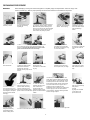
STRIKE FIRST
CORPORATION
ABC
ABC
SERVICE MANUAL (v2)
UL / ULC
DRY CHEMICAL – HAND PORTABLE
FIRE EXTINGUISHERS
All fire extinguishers should be installed, inspected & maintained in accordance with the National Fire Protection Association
(NFPA) 10, 2007 Edition “Standard for Portable Fire Extinguishers” and the local authorities having jurisdiction.
When installation, inspection or maintenance is required, Strike First Corporation strongly recommends the work to be performed
by NFPA 10 (2007) certified personnel. Fire extinguishers are pressure vessels and must be treated with respect and handled
with care. They are mechanical devices and require periodic maintenance to be sure that they are ready to operate properly and
safely.
Strike First Corporation makes O.E.M. parts available to insure proper maintenance. Substituting O.E.M. parts voids the Strike
First warranty, as well as the UL & ULC Listings. DO NOT SUBSTITUTE.
Strike First Corporation does not service, maintain or recharge fire extinguishers. This manual is published as a guide to assist
qualified service personnel in the inspection, maintenance and recharge of Strike First fire extinguishers only. This service
manual should be used in conjunction with the appropriate Parts Lists/Pictograms for each unit being serviced. No
service manual can anticipate all the possible malfunctions that may be encountered in the service of fire extinguishers. Due to
the possibility that prior service performed on this equipment may have been improperly done, it is extremely important that all
warnings, cautions and notes in this manual be carefully observed. Failure to heed these instructions could result in serious
injury.
Strike First Corporation assumes no liability for service, maintenance or recharge of fire extinguishers by publishing this service
manual.
For installation instructions of Strike First portable fire extinguishers please refer to all of the following:
1. Owner’s Manual - included with the unit
2. NFPA 10 “Standard for Portable Fire Extinguishers – 2007 Edition
3. Local authorities having jurisdiction
For operation instructions on Strike First portable fire extinguishers please refer to one or all of the following:
1. Fire Extinguisher Nameplate/Label
2. Owner’s Manual – included with the unit
3. NFPA 10 “Standard for Portable Fire Extinguishers – 2007 Edition
4. Your local authorized Strike First Distributor
WARNING:
ALWAYS WEAR EYE PROTECTION WHEN SERVICING PRESSURIZED DRY CHEMICAL FIRE
EXTINGUSIHERS.
CAUTION:
PERSONS EXPECTED TO USE THIS FIRE EXTINGUISHER SHOULD BE TRAINED IN INITIATING ITS
OPERATION AND IN THE PROPER FIRE FIGHTING TECHNIQUE.
RECHARGE FIRE EXTINGUISHERS IMMEDIATELY AFTER ANY USE
1
INSPECTION* (ref. 7.2 - NFPA 10, 2007)
The inspection procedures outlined below may not be sufficient for every jurisdiction or location and should be used in
conjunction with the NFPA 10 Standard for Portable Fire Extinguishers, 2007 Edition.
Fire extinguishers shall be manually inspected when initially placed in service. The inspection is intended to give reasonable
assurance that the extinguisher is fully charged and operable. This is done by seeing that it is in its designated place, has not
been actuated or tampered with, and there is no obvious physical damage or condition to prevent operation.
WARNING:
FOR SAFETY PURPOSES, IF AN EXTINGUISHER SHOWS SIGNS OF CORROSION OR MECHANICAL
DAMAGE, IT SHALL BE SUBJECTED TO A HYDROSTATIC PRESSURE TEST OR REPLACED.
PERIODIC INSPECTION PROCEDURE
(Monthly or more often if circumstances dictate)
Periodic inspection of the fire extinguisher shall include a check of at least the following items:
1.
2.
3.
4.
5.
6.
Location in designated place
No obstruction to access or visibility
Fullness determined by weighing or hefting
Seal and tamper indicators not broken or missing
Operating instructions on nameplate are legible and facing outward
Examine for obvious physical damage, corrosion, leakage, or clogged hose and/or nozzle.
MAINTENANCE (ref. 7.2 & 7.3 - NFPA 10, 2007)
Maintenance, servicing & recharging shall be performed by trained and certified persons having available the appropriate
servicing manual, the proper types of tools, recharge materials, lubricants, and Strike First O.E.M. replacement parts.
Fire extinguishers shall be subjected to maintenance at intervals of not more than 1 year, at the time of hydrostatic test, or when
specifically indicated by an inspection. Extinguishers taken out of service for maintenance or recharge shall be replaced by spare
extinguishers of the same type and at least an equal rating.
MAINTENANCE PROCEDURE
1.
Clean extinguisher to remove dirt, grease or foreign material. Check to make sure that the instruction nameplate and
UL/ULC manifest are securely fastened and legible. Inspect the cylinder for corrosion, abrasion and dents. If any of
these conditions are found or you doubt the integrity of the cylinder, hydrostatically test to factory test pressure, using
the proof pressure method, in accordance with CGA Pamphlet C-1 and The National Fire Protection Association (NFPA)
Pamphlet No. 10 “Standard for Portable Fire Extinguishers” 2007 Edition.
2. Inspect the extinguisher and replace any parts that are damaged, missing, corroded or O.E.M. substitute parts. Only
factory O.E.M. replacement parts are approved for use on Strike First fire extinguishers.
3. Weigh the extinguisher. Extinguisher weight MUST fall within the + / - tolerance of the total charged weight limits in the
“MAINTENANCE” section on the label. Any extinguisher not falling within the tolerance limits shall be properly
recharged.
4. Check the date of manufacture stamped on the cylinder or the date of last hydrostatic test on the label affixed to the
extinguisher. Cylinder must be hydrostatically tested every 12 years to test the pressure indicated on the nameplate.
5. Inspect the pressure gauge for damage. Depressurize and replace if necessary. If the pressure gauge indicator is
below the green “RECHARGE” it may indicate a leak or discharge. If the pressure indicator is above the green
“OVERCHARGED” it may indicate a faulty gauge or excess nitrogen. In both cases, depressurize and follow the
recharge instructions.
6. Check pull (locking) pin for freedom of movement. Replace if bent or if removal appears difficult.
7. Check the discharge lever for freedom of movement. Inspect carrying handle for proper installation. If either is
damaged, replace.
8. Remove nozzle or hose and horn assembly and inspect valve body interior for damage. Replace the hose if cut or
cracked, or if threaded couplings are damaged. Blow air through the hose and nozzle assemblies using air or nitrogen
at 50 psi (345 kPa) or less to insure that the passage is clear of foreign material.
9. Inspect valve assembly for corrosion or damage. Valve removal and / or valve part replacement should be made only
after completely discharging the contents of the cylinder.
10. Reinstall nozzle or hose and assembly
11. Install new tamper seal and record service data on the extinguisher inspection tag.
12. Install the extinguisher on the wall hanger bracket (or in vehicle bracket) in its proper location. Check for correct fit –
replace bracket if necessary.
2
RECHARGE (See Page 4 for RECHARGING PROCEDURE)
RECHARGING [NFPA 10, 7.4, 2007] IS THE REPLACEMENT OF THE EXTINGUISHING AGENT
TROUBLESHOOTING GUIDE
WARNING:
BEFORE ATTEMPING TO CORRECT ANY LEAKAGE PROBLEM, BE SURE THAT THE EXTINGUISHER IS
COMPLETELY EMPTY AND DEPRESSURIZED.
Note:
Check to determine the source of the leak before the extinguisher is empty. Leakage repairs will require that
the extinguisher be completely empty and the valve assembly removed.
When re-installing the valve assembly, the cylinder must be placed in a suitable securing vice and valve
installed hand tight.
PROBLEM
CORRECTIVE ACTION
1. Leak at collar o-ring
Remove valve assembly, clean collar thoroughly and install new collar oring.
2. Leak through valve
Remove spring and valve stem assembly. Install new valve stem
assembly. Check valve seat for scratches or foreign matter.
3. Leak at safety relief nut
Remove safety nut, disc and gasket assembly. Replace with new Strike
First safety nut, disc & gasket assembly. Tighten assembly to 25 ft-lbs. of
torque.
4. Leak during discharge under discharge lever
Remove spring and valve stem assembly. Install new valve stem
assembly. Check valve seat for scratches or foreign matter.
5. Leak during discharge
Tighten hose connection at elbow (10, 15 & 20 lb.). Replace swivel
assembly on 5 lb.
6. Defect in the cylinder*
Contact a Strike First dealer if under warranty, otherwise – mark
“CONDEMNED” and remove from service or return to owner.
LIMITED WARRANTY
STRIKE FIRST CORPORATION (“STRIKE FIRST”) warrants its fire extinguishers (“Products”) to be free from defects in material and workmanship for a period of six
(6) years from the date of manufacture. Strike First’s responsibility for defects in material or workmanship are limited to repair or replacement of the products for the
original retail purchaser (“Consumer”) only. This limited warranty does not cover defects resulting from modification, abuse, accident, alteration, misuse, exposure to
corrosive conditions, or improper installation or maintenance. STRIKE FIRST is not responsible for the installation or the maintenance of the Products.
Defective Products for which a valid claim has been made shall be returned to STRIKE FIRST’s facility at Scarborough, ON (416) 299-7767 for repair or replacement
(or to other repair facilities pursuant to STRIKE FIRST’s prior written authorization), and transportation costs to such locations shall be paid by Consumer.
STRIKE FIRST DOES NOT ACCEPT LIABILITY BEYOND THE REMEDIES PROVIDED IN THIS LIMITED WARRANTY, WHETHER BASED ON CONTRACT,
NEGLIGENCE, STRICT LIABILITY OR OTHERWISE, INCLUDING WITHOUT LIMITATION DAMAGES FOR ANY PERSONAL INJURY, PROPERTY DAMAGE, OR
ANY DIRECT, INDIRECT, SPECIAL, CONSEQUENTIAL, INCIDENTAL, EXEMPLARY OR PUNITIVE DAMAGES, AND INCLUDING WITHOUT LIMITATION ANY
LIABILITY FOR THIRD PARTY CLAIMS, IN EACH CASE EVEN IF STRIKE FIRST HAS BEEN ADVISED OF THE POSSIBILITY THEREOF. LAWS OF SOME
JURISDICTIONS DO NOT ALLOW THE DISCLAIMER OF CONSEQUENTIAL OR OTHER TYPES OF DAMAGES, AND CONSUMERS MAY ALSO HAVE OTHER
RIGHTS WHICH VARY FROM JURISDICTION TO JURISDICTION. UNDER SUCH CIRCUMSTANCES, THIS LIMITED WARRANTY AND THE LIMITATIONS AND
DISCLAIMERS HEREIN SHALL BE TO THE GREATEST EXTENT PERMITTED BY LAW.
THIS LIMITED WARRANTY CONTAINS THE ENTIRE WARRANTY PROVIDED BY STRIKE FIRST, AND SHALL BE IN LIEU OF ANY AND ALL OTHER
WARRANTIES OR CONDITIONS, WHETHER EXPRESS OR IMPLIED, STATUTORY OR OTHERWISE, INCLUDING WITHOUT LIMITATION, IMPLIED
WARRANTIES AND CONDITIONS OF MERCHANTABILITY AND FITNESS FOR A PARTICULAR PURPOSE.
Neither the Product distributor nor any other third party is authorized to make any conditions, representations or warranties on STRIKE FIRST’s behalf. STRIKE FIRST
neither assumes nor authorizes any representative or other person to assume for it any obligation or liability other than as expressly set forth herein.
Any disputes regarding or relating to this limited warranty will be resolved in the sole discretion of STRIKE FIRST.
REFERENCES IN THIS MANUAL:
AVAILABLE FROM:
NFPA 10
Standard for Portable Fire Extinguishers
2007 Edition
National Fire Protection Association
1 Batterymarch Pk.
Quincy, MA 02169-7471
www.nfpa.org
*CGA C-1
“METHODS FOR HYDROSTATIC
TESTING OF COMPRESSED GAS
CYLINDERS”
Compressed Gas Assoc., Inc.
4221 Walney Rd., 5th Floor
Chantilly, VA 20151
www.cganet.com
3
RECHARING PROCEDURE
WARNING:
Before attempting to recharge be sure the extinguisher is completely empty and depressurized. Failure to comply could
result in personal injury, death or property damage due to the violent movement of the loosened components.
1. Remove the hose
assembly or nozzle.
2. Invert extinguisher and
discharge all remaining
expelent gas.
6. Remove body o-ring.
7. With a small brush, thoroughly clean the interior and exterior
of the valve body threads, paying particular attention to the
seat area. Pay particular attention to the pressure relief
groove cut into the threads of the valve body.
8. Carefully inspect the new
Valve Body O-ring and install.
Be carefull not to damage o-ring
on valve body threads.
9. Lubricate o-ring
circumference. Strike First
recommends "Parker OLube".
10. Clean outlet orfice
with a small brush.
11. Clean the valve seat itself
containing the sealing rubber.
Strike First recommends
replacing the valve stem
assembly at every major service
interval.
13. Re-insert valve stem
assembly into the valve body.
Push into place with your finger.
14. Return spring to
syphon tube, turn syphon
tube clockwise into valve
body.
3. Remove the valve and syphon tube from
the cylinder by rotating counter clockwise.
Mark valve and cylinder if servicing more
than one unit. Remove the chemical residue
by inverting the cylinder. Failure to do so
could result in the packing of powder.
12. Place a small amount of
lubricant along the
circumferance of the small oring only.
4. Detach syphon tube from
valve with counterclockwise
rotation. Remove spring.
18. Place the pressurizing adaptor into valve
outlet. Move regulator to desired pressure (use
Dry Nitrogem ONLY). Connect Nitrogen source
and allow pressure to felt at valve stem. Push
down discharge handle. Nitrogen will be forced
16. Return cleaned valve and
17. Rotate the valve in a
around valve stem and down syphon tube. A
syphon tube to the correct
clockwise direction until a
small bump may be noticed due to the
cylinder. NOTE: After filling
"click" is heard. This
15. Fill the unit with the
displacement of dry chemical in the syphon tube.
cylinder, replace valve and
engages threads and
correct amount and type of
Once the gauge on the unit has reached the
minimizes stripping. Hand
dry chemical as stated on the syphon tube immediately while
correct pressure, release the discharge handle.
fire extinguisher nameplate. powder is still in an aerated state. tighten valve with clockwise
Remove recharge adaptor.
rotation.
Clean the cylinder threads
thoroughly.
21. Place a pull pin
through the valve body
and discharge handle.
Attach a sealing device.
23. Authourize service tag & date.
22. Check nozzle and/or hose for blockage and retrun to unit.
4
5. Using your finger or a
suitable tool, press down
on the valve stem located
under the discharge
handle.
20. Thoroughly chech all
areas on the unit that may
leak pressure.
a) welds
b) gauge face & threads
c) valve body o-ring
d) valve stem seat