1
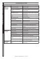
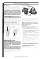
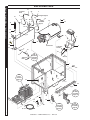
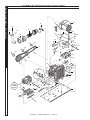
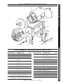
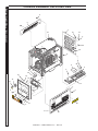
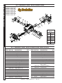
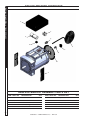
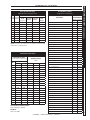
PDHW
SERVICE MANUAL
■ PDHW5-35624E
1.110-060.0
■ PDHW5-35624E/G 1.110-062.0
Se
■ PDHW5-35624E/SS
1.110-061.0
■ PDHW5-35624E/G/SS 1.110-063.0
nD
EC
TAC
H/H
OUR
1/10
PRE
W
AR
CAU
CIÓN
8.932965.0
NO
NE
NI
EXP / AVE NG
RTIS
BEL OSE
SEM
TS D
KEEP CAN PUL
ENT
CLEAR
CAULEYS
SE AND
INJ
POLE
SE
DES
PAS
AS
WHIL
Y CORR IS
ACER PUED
OPERE MACH
QUE
ATING INERY
EN EAS
COU
SI
URY
PEUV RRO M CAUS EXPU
ÀQUINAR
ROCHEENT IES
DA ESTA
A EST
CAU OU
ÑO S
R LORSQ
Á
SERPOU
LIES FUNC
UE
L’APPDES
EXPO IONAN
AREILBLES
SÉES DO
EST SURE
EN
OP S
PRE
ÉRATI
CAU
ON
CION
/ AVE
RTIS
DIS"RIS
SEM
CONK
GRO OF
ENT
NEC
S’APP
CA
UT
IO
N
DES
BEF UND INJU
T BATRY"
DE CON"RIE
ORE TER
BAT ECTSGO
SER MINTER
ERI AR
DE
VIC AL Y
A
ANTTER LES
ING
ES MIN ION
DET "RIS
DE AL "
TERACH QUE
DARDE
TIER
MIN ER
SER
AL BATATT
VICRA
AVA TEREIN
IO
NT IE TE"
DE TER
SERRAI
VIC N
E
9.801
-366.
1.
OP
ER
AT
Rea
ING
usin d Ope
INS
rato
Cong.
TR
r’s
(minnect
UC
Man
wateimumstan
TIO
ual
3.
care
NS
Sec r on. sizedard
gard
4.
fully
ure
Che high 5/8”
at en hose befo
5.
20
Starck oil pres
re
psi) to
6.
To t engi and sure
and mac
7.
heat ne fuel
hose
turn hine
To
shut wate and levels. to
allow
trigg
mac
dow r, turn
with wate
er
hine
n
clea r mac burn spra
.
to
y
n wate
coolhine er on. gun.
, turn
. Flus
r befo
burn
re h dete er
turn rgen off
ing
and
engit lines
ne
off.
2.
TO
OF REDU
INJURCE
OPER
RISK
Y READ
MANUATOR
FULLYAL ’S
USING CARE
BEFOR
MACH .
THIS E
BE INE
BY USED TO
QUALIONLY
OPERA
FIED
TORS.
0
RISK
INJUROF
PROTEY—
EYEWECTIVE
CLOTH AR
BE
INGAND
WORN
MUST
opera
machiting when
ne. this
LEA
CIONEL MANU
ESTE ANTES
USADEQUIP AL OPER
DE
OPER O
O USAR A
SOLAM
DOS. ADOR DEBE SE. ES ENTESER
CALIF POR
LIRE
ICA
L’OPELE
MANU
UTILISRATEU
REIL ATION EL DE
R AVAN
PAR DOIT
. CET T
QUALDES ETRE
APPA
OPER UTILIS
IFIES.
ATEUR
E S
PROT
CUANEJASE
EQUIPDO LOS
O. SE OPEROJOS
DES
E ESTE
LUNET
SECUR
PORT ITE TES
opereEES DOIVEDE
z cet lorsquNT
appar e ETRE
vous
eil.
INS
TR
UC
CIO
Lea
NE
de el man
2.
usar
S DE
Con se. ual
de
llaveecte
OP
oper
3.
ER
Con del le man
ació
agua
4.
n ante AC
guer
Rev ecte
ION
5.
le .
a del
s
Encise los man
jardi
presiend nive guer
ny
6.
a
les a de
Paraión. el moto
abra
de
7.
alta
acei
la
Al cale
r, abra
tes pres
la term ntar
ión.
man inar,
el y com
hag gue agua
gatil
apag ,
enci
lo bust
boma circu ra
y logreibles
ba. lar del ue el enda
.
el dete quem el
agu rgen
quem
a fira te ado
con r, purgador
ante
agu ue .
s de
a,
apagy
ar
la
1.
W
AR
NI
RISK
EXPLOOF
Opera SION.
NG
wherete
only
flame open
is
or
permi
torch
not
spraytted.
mable
flamDo
RISK liquid
Do OF
s. FIRE.
fuelnot add
when
machi
opera ne the
ting.is
RISK
INJUROF
SURF Y—HO
CAUSACES
T
Use E BURN
CAN
only
signed
de S.
areas grippi
gun of
and sprayng
wand.
1.
EC
MO
Lire
DE
utilisle man
D’E
Reli ation uel
MP
de
(miner à .
LO
l’opé
3.
l’app
I
Reli imum
rate
areil
4.
ur
Vérier le 5/8”
5.
boya à 20un boya avan
Partfier le
t
u
psi) u
gachir le nive hau
et à jardi
6.
mote au te pres
ouvr
Pou ette
d’hu
ir n
7.
de ur
Pou r chau la de ile sion l’eau
de
et r arrê ffer poig la pom la à l’app.
née
laiss
pe pom arei
dete er ter l’eau
pisto et pe.
l’app , allum
l.
pomrgen refro
let. pres
pe. t à idirareil
er
ser
, ferm
l’eau l’eau
le
la
brûle
prop . Rincer
ur.
le
re
brûle
avaner la
ligneur
t d’arr
êterde
la
2.
/ PR
RIESG
AU
Use O
el DE EXPLO
donde
produ
permi el cto
fuego enSION
inflamtidos.
áreas—
ables.No o llama
rocie
RISQU
sean
Utiliser E
liquid
D’EXP
nue aux
os
LOSIO
endroit
de est permis
liquide
N
DE
e. Nes où une
FEU. s inflamm
—
sence
pas flamm
machi/de Ne pas ables.vaporis
e
ne fuel ajoute
er
est tandis
r RISQU
en
operaque dés
E
SUPER
tion.la Use FICIES
ladassolam
CALIE
del ente
gatillolas NTES
SURF
áreas —
TouchACES
y la
ais
isoléeer CHAU lanza.
seulem
et
s des
DES
lances
ent —
poign
le
.
ée partie
pistol s
ets
CI
ON
/ AV
ER
TIS
RISK
OF
ASPHY
Use XIATIO
only
ventila
in N.
ted well
area.
RISK
INJECOF
OR TION
SEVER
INJUR
TO Y E
PERSO
Keep
nozzleclearNS.
HOT .
of
CHARDIS
FLUIDGE touch .
dischaor Do not
streamrgedirect
perso at
ns.
ME
RIESG
FO
R
BE
ST
RE
SU
LTS
DE
TER
US
E
Neve
•
r Use:
Bleac
•
Liquidh,
oil) s chlori
•
conta ne
Tri-so
produ
•
Amm dium ining
cts
•
Acid- onia phosp solve and
These
basedprodu hate nts (i.e.other
surfac chem
cts produ
paintcorro
produ
Use e
beingicals
sive
thinne
cts
cts
manumanu
will
chem
clean
r, gasol
al. factur
harm
icals
er’s ed.
the
ine,
deter
unit
and
gents
will
as
recom dama
mend ge the
ed
in
GE
NTS
CA
UT
ION
SE
NT
produ O
ventil ctoDE ASFIX
en
ación
un IA.
area
RISQU
adecu
de Use
dans E
ada.
el
un D’ASP
endro HYXIE
it bien .
Utilise
aéré.
RIESG
r
LESIO O
DE
SONA NES
PENET
del S. SEVER
alcancManté RACIÓ
AS
NO
DESCA e de ngaseA PER
boqui fuera
ENTE RGA
lla.
toque A
ALTADE AGUA
agua ni
dirijaPRESI CALI
RISQUa otras
el ON
tenir E
flujo — perso
EAU loinDE BLESS del
nas.
No
SIONCHAUdes
URES
dirigeA DE buses
LA SOUS . .
perso r le SORT
jet IE PRES Se
nnes.
d’eau —
vers Ne des pas
SPRA
KICK Y
GUN
Hold BACK
both with
LA
.
hand
LA PISTO
s
las PRESILA SE
.
dos ÓN MUEV
mano—
LA
POIGN s. Soste
E CON
REPO
mainsUSSEEE
nga
RISK
PISTO
con
.
—
tions OF
LET
Tenir
from dry ELECT
and ROCU
à deux
Discoelectr
off
RIESG
servicnnectical the TION
secas O
ing. fromwiringgroun .
necte y DE ELECT
Keep
arriba
electrand d. Keep
RISQUla
all
corriendel ROCU
ical compo sprayconne
secs E
supplynents.
D’ELE te suelo. CIÓN
posanet étre
awayc
eléctri
—
CTRO No rocie
before
de tes suspen
ca
faire et
CUTIO
antes compo
Mante
dus.
une fils électri
nga
répara
No N — de
nentes
ques.jamais dar servic todas
tion.
eléctri las
Tous
Coupe projete
io.
cos. conne
r l’alimer les fils
Descoccione
de
l’eaudoiven
ntatati
s
sur t
on les être
électri commainte que
nus
avant
-
DE
TE
RG
VAL
VUL
SOU
PAPA DE
E DEDET
DETERG
ERGENT
ENTE
EN
T VA
LV
E
9.80
1-36
7.0
89200980-1
LIS T E D
For technical assistance or the dealer nearest you,
consult our web page at www.landa.com
®
8.920-098.0
CONTENTS
Troubleshooting4-7
Maintenance & Service
8-10
Preventive Maintenance
11
Exploded View & Parts List
12-13
Power Platform Exploded View & Parts List
14-16
Coil Assembly Exploded View & Parts List
17
Control Box, Exploded View & Parts List
18-19
Burner/Fuel Filter Exploded View & Parts List
20
Unloader/Pump Exploded View & Parts List
21
Chassis Exploded View & Parts List
22-23
Hose & Spray Gun Assembly & Parts list
24
Specifications25
Landa Surefire Replacement Parts
26-27
LT Pump Exploded View and Parts List
28-29
AB30 Voltmaster Generator Assembly & Parts List
30
Wattage Charts
31
VRT 3 Unloader Exploded View and Parts List
32
Warranty
Model Number ______________________________
Serial Number ______________________________
Date of Purchase ___________________________
The model and serial numbers will be found on a decal attached
to the pressure washer. You should record both serial number and
date of purchase and keep in a safe place for future reference.
3
8.920-098.0 • LANDA PDHW Service • REV. 8/12
PROBLEM
POSSIBLE CAUSE
SOLUTION
LOW
OPERATING
PRESSURE
Faulty pressure gauge
Install new gauge.
Insufficient water supply
Use larger supply hose; clean filter at water inlet.
Old, worn or incorrect spray
nozzle
Match nozzle number to machine and/or replace
with new nozzle.
Belt slippage
Tighten or replace; use correct belt.
Plumbing or hose leak
Check plumbing system for leaks. Re-tape leaks
with teflon tape.
Faulty or mis-adjusted unloader
valve
Adjust unloader for proper pressure. Install repair
kit when needed.
Worn packing in pump
Install new packing kit.
Fouled or dirty inlet or discharge
valves in pump
Clean inlet and discharge valves.
Worn inlet or discharge valves
Replace with valve kit.
Obstruction in spray nozzle
Remove obstruction.
Leaking pressure control valve
Rebuild or replace as needed.
Slow engine RPM
Set engine speed at proper specifications.
Pump sucking air
Check water supply and possibility of air
seepage.
Valves sticking
Check and clean or replace if necessary.
Unloader valve seat faulty
Check and replace if necessary.
Little or no fuel
Fill tank with fuel.
Improper fuel or water in fuel
Drain fuel tank and fill with proper fuel.
Clogged fuel line
Clean or replace.
Plugged fuel filter
Replace as needed.
Mis-adjusted burner air bands
Readjust air bands for clean burn.
Little or no fuel pressure from fuel
pump
Increase fuel pressure to specification and/or
replace fuel pump. Test with pressure gauge.
Faulty burner transformer
Test transformer for proper arc between
contacts. Replace as needed.
Disconnected or short in electrical
wiring
All wire contacts should be clean and tight. No
breaks in wire
PRESSURE WASHER
Troubleshooting Guide
TROUBLESHOOTING
BURNER WILL
NOT LIGHT
(continued on
next page)
4
8.920-098.0 • LANDA PDHW Service • REV. 8/12
PROBLEM
POSSIBLE CAUSE
SOLUTION
BURNER WILL
NOT LIGHT
(continued from
previous page)
Flex coupling slipping on fuel pump
shaft or burner motor shaft
Replace if needed.
On-Off switch defective
Check for electrical current reaching
burner assembly with burner switch on.
Heavy sooting on coil and burner
can cause interruption of air flow
and shorting of electrodes
Clean as required.
Improper electrode setting
Check and reset according to diagram in
Operator’s Manual.
Fuel not reaching combustion
chamber
Check fuel pump for proper flow.
Check solenoid flow switch on machines
with spray gun control, for proper
on-off fuel flow control.
Clogged burner nozzle
Clean as required.
Thermostat faulty or slow engine
speed
Increase engine
RPM to increase voltage.
Flow switch malfunction
Remove, test for continuity and replace as
needed.
Flow solenoid malfunction
Replace if needed.
Valves worn
Check and replace if necessary.
Blockage in valve
Check and replace if necessary.
Pump sucking air
Check water supply and air seepage at joints
in suction line.
Worn piston packing
Check and replace if necessary.
Engine Altitude
The engine is preset for operation at
altitudes below 1000 feet above sea level.
If operated at higher altitudes, it may be
necessary to adjust the engine. Contact your
local authorized engine sales and service
center for details.
Improper fuel or water in fuel
Drain tank and replace contaminated fuel.
Improper air adjustment
Readjust air bands on burner assembly.
Low fuel pressure
Adjust fuel pump pressure to specifications.
Plugged or dirty burner nozzle
Replace nozzle.
Faulty burner nozzle spray pattern
Replace nozzle.
FLUCTUATING
PRESSURE
MACHINE SMOKES
PRESSURE WASHER Troubleshooting Guide
TROUBLESHOOTING
Heavy accumulation of soot on coils Remove coils and burner assembly, clean
and burner assembly
thoroughly.
Misaligned electrode setting
Realign electrodes to specifications.
Obstruction in smoke stack
Check for insulation blockage or other
foreign objects.
Low engine RPM
Increase RPM
5
8.920-098.0 • LANDA PDHW Service • REV. 8/12
Troubleshooting Guide
PRESSURE WASHER
TROUBLESHOOTING
PROBLEM
POSSIBLE CAUSE
SOLUTION
LOW WATER
TEMPERATURE
Improper fuel or water in fuel
Replace with clean and proper fuel.
Low fuel pressure
Increase fuel pressure.
Weak fuel pump
Check fuel pump pressure. Replace pump
if needed.
Fuel filter partially clogged
Replace as needed.
Soot build-up on coils not
allowing heat transfer
Clean coils.
Improper burner nozzle
See specifications. (page 32)
Incoming water to machine
warm or hot
Lower incoming water temperature.
Fuel pump pressure too high
See specifications for proper fuel pressure.
Fuel pump defective
Replace fuel pump.
Detergent line sucking air
Tighten all clamps.
Check detergent lines for holes
Defective temperature switch
Replace.
Incorrect fuel nozzle size
See specifications for
proper fuel nozzle. (page 32)
Insufficient water supplied
Check water G.P.M. to machine.
Restricted water flow
Check nozzle for obstruction, proper size.
Air in suction line
Check water supply
and connections on suction line.
Broken or weak inlet or
discharge valve springs
Check and replace if necessary.
Excessive matter in valves
Check and clean if necessary.
WATER
TEMPERATURE
TOO HOT
PUMP
NOISY
Worn bearings
Check and replace if necessary.
PRESENCE
OF WATER
IN OIL
Oil seal worn
Check and replace if necessary.
High humidity in air
Check and change oil twice as often.
WATER
DRIPPING
FROM
UNDER PUMP
Piston packing worn
Check and replace if necessary.
O-Ring plunger retainer worn
Check and replace if necessary.
Cracked piston
Check and replace if necessary.
Pump protector
Lower water supply pressure. Do not
run with spray gun closed longer than 2
minutes.
6
8.920-098.0 • LANDA PDHW Service • REV. 8/12
PROBLEM
POSSIBLE CAUSE
SOLUTION
OIL DRIPPING
Oil seal worn
Check and replace if necessary.
EXCESSIVE
VIBRATION
IN DELIVERY LINE
Irregular functioning of the valves
Check and replace if necessary.
DETERGENT
NOT DRAWING
Air leak
Tighten all clamps. Check detergent
lines for holes.
Restrictor in float tank is missing
Replace restricter. Check for proper
orifice in restrictor.
Filter screen on detergent suction
hose plugged
Clean or replace.
Dried up detergent plugging
metering valve
Disassemble and clean thoroughly
High viscosity of detergent
Dilute detergent to specifications.
Hole in detergent line(s)
Repair hole.
Low detergent level
Add detergent, if needed.
Pump sucking air
Check water supply and possibility
of air seepage.
Valves sticking
Check and clean or replace if
necessary.
Nozzle incorrectly sized
Check and replace if necessary
(See serial plate for proper size).
Unloader valve seat faulty
Check and replace if necessary.
Worn piston packing
Check and replace if necessary.
Fuel pump seized
Replace fuel pump.
Burner fan loose or misaligned
Position correctly, tighten set screw.
Defective control switch
Replace switch.
Loose wire
Check and replace or tighten wiring.
Defective burner motor
Replace motor.
Relief valve defective
Replace or repair.
PUMP RUNNING
NORMALLY BUT
PRESSURE LOW
ON INSTALLATION
BURNER MOTOR
WILL NOT RUN
RELIEF VALVE
LEAKS WATER
PRESSURE WASHER Troubleshooting Guide
TROUBLESHOOTING
7
8.920-098.0 • LANDA PDHW Service • REV. 8/12
PRESSURE WASHER
SERVICE MANUAL
MAINTENANCE & SERVICE
Check List:
1.Check to see that water pump is properly
lubricated.
2.Follow winterizing instructions to prevent freeze
damage to pump and coils.
3. Always neutralize and flush detergent from system
after use.
4. If water is known to be high in mineral content, use
a water softener on your water system, or de-scale
as needed.
5. Do not allow acidic, caustic or abrasive fluids to be
pumped through system.
6. Always use high grade quality cleaning products.
7. Never run pump dry for extended periods of time.
8. Use clean diesel. Clean or replace fuel filter every
300 hours or 6 months of operation. Avoid water
contaminated fuel as it will damage the fuel pump.
9. If machine is operated with smoky or eye burning
exhaust, coils will soot up, not letting water reach
maximum operating temperature.
10.Never allow water to be sprayed on or near the
engine or burner assembly or any electrical component.
11. Periodically delime coils as per instructions.
12. Check to see that engine is properly lubricated.
It is advisable, periodically, to visually inspect the
burner. Check air inlet to make sure it is not clogged
or blocked. Wipe off any oil spills and keep equipment
clean and dry.
The flow of combustion and ventilating air to the burner
must not be blocked or obstructed in any manner.
The area around the Landa washer should be kept
clean and free of combustible materials, gasoline and
other flammable vapors and liquids.
Unloader Valves:
Unloader valves are preset and tested at the factory
before shipping. Tampering with the factory setting may
cause personal injury and/or property damage, and will
void the manufacturers warranty.
8
pressed air is available, an air fitting can be screwed
into the float tank by removing the float tank strainer
and fitting. Then inject the compressed air. Water will
be blown out of the machine when the trigger on the
spray gun is opened.
High Limit Hot Water Thermostat:
For safety, each machine is equipped with a temperature sensitive high limit control switch. In the event that
the water should exceed its operating temperature, the
high limit control will turn the burner off until the water
cools then automatically reset itself. The thermostat
sensor is located on the discharge side of the heating coil. The thermostat control dial is located on the
control panel.
Pumps:
Use only SAE 10/40W non-detergent oil. Change oil
after first 50 hours of use. Thereafter, change oil every
three months or at 500 hour intervals. Oil level should
be checked through use of dipstick found on top of
pump, or the red dot visible through the oil gauge window. Oil should be maintained at that level.
Cleaning of Coils:
In alkaline water areas, lime deposits can accumulate
rapidly inside the heating coil. This growth is increased
by the extreme heat build up in the coil. The best preventative for liming conditions is to use high quality
cleaning detergents. In areas where alkaline water is
an extreme problem, periodic use of Landa Deliming
Powder (Landa Part #8.718-911.0) will remove lime
and other deposits before coil becomes plugged.
(See Deliming instructions for use of Landa Deliming
Powder.)
Deliming Coils:
Periodic flushing of coils or optional float tank is
recommended.
Step 1:Fill a container with 4 gallons of water, then add 1 lb. of deliming powder. Mix thoroughly. Pour
mixture into float tank.
Winterizing Procedure:
Step 2:Remove wand assembly from spray gun and put spray gun into float tank. Secure the trigger on the
spray gun into the open position.
Damage due to freezing is not covered by warranty.
Adhere to the following cold weather procedures whenever the washer must be stored or operated outdoors
under freezing conditions.
Step 3:Turn engine on, allowing solution to be pumped
through coils back into the float tank. The solution
should be allowed to circulate 2-4 hours or until the
color changes.
During winter months, when temperatures drop below
32°F, protecting your machine against freezing is necessary. Store the machine in a heated room. If this is
not possible then mix a 50/50 solution of anti-freeze
and water in the float tank. Turn the engine on to siphon
the anti-freeze mixture through the machine. If com8.920-098.0 • LANDA PDHW Service • REV. 8/12
Step 4:After circulating solution, flush the entire system with fresh water. Clean out float tank and then reinstall wand assembly to spray gun.
Removal of Soot and Heating Coil:
Rupture Disk:
If pressure from pump or thermal expansion should
exceed safe limits, the rupture disk will burst allowing
high pressure to be discharged through hose to ground.
When disk ruptures it will need to be replaced. Torque
new rupture disk to 35 ft. lbs.
Fuel:
Diesel fuel must be clean, fresh, meet fuel specifications and be sourced from a known and reputable
supplier. Clean, fresh and properly specified diesel
fuel will provide assurances of maximum engine performance and maximum fuel injection system longevity.
The use of out-of-spec, dirty or questionable quality
diesel fuel will result in engine performance and start
ability problems as well as reductions in engine and
fuel injection system life.
Use clean fuel oil that is not contaminated with water
and debris. Replace fuel filter and drain tank every 100
hours of operation.
All burner combustion system designs are geared
toward the use of commercial grade diesel fuels. As
such, use of fuels other than those designated "DF",
i.e. DF2 (No. 2 Diesel Fuel), will result in degradation
of performance and/or reduction in component life. It
is understood that applications in certain situations require the use of fuels other than No. 2 diesel fuel. See
list of various fuels and comments pertaining to each.
Diesel engines are designed to operate on No. 2 diesel
fuel. However, some geographical areas, change the
diesel fuel supply depot to No. 1 diesel fuel in the winter
months because of the col winter temperatures. No. 2
diesel fuel provides maximum viscosity and lubricity
but can have "waxing" problems at lower temperatures.
We expressly recommend the use of No. 2 diesel fuels
when temperatures are at or above 14°F. We recommend that No. 1 diesel fuel be used when temperatures
are at or below 14°F. The use of either EPA-high sulfur,
off-highway diesel fuel or EPA-low sulfur, on-highway
fuel for non-CARB certified engines is allowed. CARB
certified engines must consume only EPA-low sulfur
diesel fuels conforming to EPA 40 CFR 86-113-94.
Fuel Control System:
This machine utilizes a fuel solenoid valve located on
the fuel pump to control the flow of fuel to the combustion chamber. The solenoid, which is normally closed,
is activated by a flow switch when water flows through
it. When the operator releases the trigger on the spray
gun, the flow of water through the flow switch stops,
turning off the electrical current to the fuel solenoid.
The solenoid then closes, shutting off the supply of
fuel to the combustion chamber. Controlling the flow
of fuel in this way gives an instantaneous burn-or-noburn situation, thereby eliminating high and low water
temperatures and the combustion smoke normally
associated with machines incorporating a spray gun.
Periodic inspection, to insure that the fuel solenoid
valve functions properly, is recommended. This can
be done by operating the machine and checking to
see that the burner is not firing when the spray gun is
in the OFF position.
SERVICE MANUAL
In the heating process, fuel residue in the form of soot
deposits may develop between the heating coil pipe
and block air flow which will affect burner combustion.
When soot has been detected on visual observation,
the soot on the coil must be washed off after following
the coil removal steps (See Coil Removal on page
17).
We do not recommend the use of "heating oil",
blended fuel/waste engine oil or low grade diesel fuel
of any kind. The use of aviation fuels - JP4, JP5 or
JP8 must be approved on an application basis and
is not recommended for broad range commercial
applications.
PRESSURE WASHER
MAINTENANCE & SERVICE
Fuel Pressure Adjustment:
To control water temperature, adjust fuel pressure
by turning the regulating pressure adjusting screw
clockwise to increase, counterclockwise to decrease.
Do not exceed 200 psi. NOTE: When changing fuel
pump, a bypass plug must be installed in return port
or fuel pump will not prime.
Burner Nozzle:
Keep the tip free of surface deposits by wiping it with
a clean, solvent saturated cloth, being careful not to
plug or enlarge the nozzle. For maximum efficiency,
replace the nozzle each season.
Electrodes Setting:
(See Illustration Below)
5/32" Gap
Electrode
7/16"
Nozzle
1/16"
Top View
Side View
9
8.920-098.0 • LANDA PDHW Service • REV. 8/12
PRESSURE WASHER
SERVICE MANUAL
MAINTENANCE & SERVICE
Burner Air Adjustment
Air Adjustment:
The oil bur ner on this machine is preset for
operation at altitudes below 1000 feet. If operated at
higher altitudes, it may be necessary to adjust the air
band setting. Adjust air band for #1 or #2 smoke spot
on the Bacharach scale. A one-time initial correction
for your location will pay off in economy, performance,
and extended service life. If a smoky or eye-burning
exhaust is being emitted from the stack, two things
should be checked. First, check the fuel to be certain
that kerosene or No. 1 home heating fuel is being used.
Next, check the air adjustment on the burner.
To Adjust Beckett Burner: Start machine and turn
burner ON. Loosen two locking screws found in the
air shutter openings (refer to illustration) and close air
shutter until black smoke appears from burner exhaust
vent. Note air band position. Next, slowly open the air
shutter until white smoke just starts to appear. Turn
air shutter halfway back to the black smoke position
previously noted. Tighten locking screws.
If the desired position cannot be obtained using only
the air shutter, lock the air shutter in as close a position
Air Shutter
Locking Screw
Air Band
Air Band
Air Band Locking Screws
CAUTION: If white smoke appears from burner
exhaust vent during start-up or operation, discontinue use and readjust air bands.
NOTE: If a flue is installed, have a professional
serviceman adjust your burner for a #1 or #2 smoke
spot on the Bacharach scale.
Coil Removal:
Removal of coil because of freeze breakage, or to clean
soot from it can be done quickly and easily.
Air
Shutter
Air Shutter
Locking Screw
Reference Numbers
Air Band
Locking Screw
as can be obtained, then repeat the above procedure
on the air band setting.
LANDA Sure Fire Oil Burner
Burner Air Adjustment: The oil burner on this machine is preset for operation at altitudes below 1000
feet. If operated at higher altitudes, it may be necessary
to adjust the air band for a #1 or #2 smoke spot on the
Bacharach scale.
To adjust, start machine and turn burner ON. Loosen
two locking screws found on the air band and close air
band until black smoke appears from burner exhaust
vent. Note air band position. Next, slowly open the air
band until white smoke just starts to appear. Turn air
band halfway back to the previously noted position.
Tighten locking screws.
1. Disconnect hose from pump to inlet side of the coil.
2. Carefully disconnect the thermostat sensor making
sure you do not crimp the capillary tube.
3.Remove burner assembly from combustion
chamber.
4. Remove the 3-3/8” bolts from each side of coil and
tank assembly (these bolts are used to fasten tank
to chassis).
5. Remove fittings connected to the 1/2” pipe nipples
from inlet and discharge sides of coil.
6. Remove top tank wrap, bend back insulation tabs
and fold back blanket.
7. Remove bolts that hold down coil to bottom wrap.
8. Remove coil.
9. Replace or repair any insulation found to be torn
or broken.
10. Remove insulation retainer plates.
Coil Reinstallation:
To reinstall new or cleaned coil, reverse steps 9 through 1.
10
8.920-098.0 • LANDA PDHW Service • REV. 8/12
MAINTENANCE SCHEDULE
Engine Oil
SAE 10W-30
or 15W-40
Air Cleaner
Inspect
Daily
Change
Every 100 hours
Filter
Every 200 hours
Inspect
Every 50 hours or monthly
Clean
Every 3 months
Check monthly
Engine Fuel Filter
300 hours or 6 months
Clean Fuel Tank(s)
Annually
Replace Fuel Lines
Annually
Pump Oil
(Non-detergent
SAE10/40W)
SERVICE MANUAL
Battery Level
PRESSURE WASHER
PREVENTATIVE MAINTENANCE
Inspect
Oil level daily
Change
After first 50 hours, then every 500 hours or annually
Clean Burner Filter
Monthly (More often if fuel quality is poor)
Remove Burner Soot
Annually
Burner Adjustment/Cleaning
Annually
Replace Burner Nozzle
Annually
Descale Coil
Annually (More often if required)
Replace High Pressure Nozzle
Every 6 months
Replace Quick Connects
Annually
Clean Water Screen/Filter
Weekly
Replace HP Hose
Annually
OIL CHANGE RECORD
Check pump oil level before first use of your new Power Washer. Change pump oil after first 50 hours and
every 3 months or 500 hours thereafter. Use SAE 10/40W non-detergent.
Date Oil Changed
Month/Day/Year
No. of Operating Hours
Since Last Oil Change
Brand Name and
Type of Oil (See above)
11
8.920-098.0 • LANDA PDHW Service • REV. 8/12
SERVICE MANUAL
PRESSURE WASHER
EXPLODED VIEW
18
To Burner
Filter
22
7
To Engine Bypass
5
16
36
18
17
18
35
9
15
To Burner
Bypass
18
30
37
26
19
14
38
13
19
6
6
24
20
12
To
Control Box
23
8
2
To Engine
Starter
41
29
27
18
28
See
Fuel Filter
Assembly
Page 20
To Engine
Filter
To
Ground
1
4
See
Power
Platform
Page 14
33
21
89200980-2
23
23
40
23
34
26
25
32
31
31
39
See
Air Filter
Assembly
Page 14
32
10
11
3
See
Unloader
Assembly
Page 21
12
8.920-098.0 • LANDA PDHW Service • REV. 8/12
See
Fuel Filter
Assembly
Page 20
ITEM PART NO.
DESCRIPTION
1
8.919-950.0
8.919-951.0
WLMT, Skid, PDHW
WLMT, Skid, PDHW, SS
2
8.706-600.0
DESCRIPTION
1
1
32
8.718-812.0
Screw, 10/32" X 3/4"
2
33
8.706-902.0
Nipple, 3/4" JIC x 1/2" NPT
1
Battery, Box, M-100, Large
1
34
9.802-696.0
Nut, 10/32" NF, Kep
2
3
8.920-106.0
8.920-173.0
WLMT, Support, Coil PDHW
WLMT, Support, Coil PDHW
SS
1
35
8.706-500.0
Elbow, 3/16 Zinc
1
36
9.802-254.0
Hose, 1/4" Push-on
4
9.802-146.0
Swivel, 1/2" MP x 3/4" GHF
w/Strainer
37
8.912-192.0
Wrap, Top, Stainless
1
38
9.802-071.0
Trim, 750
5
Hose, 1/4" Push-On
28"
39
8.920-286.0
Wiring Harness PDHW
6
9.802-708.0 Screw, 5/16 x 3/4
2
7
8.709-069.0
Clamp, Screw
1
8
8.706-941.0
Hose Barb, 1/4" Barb x MPT,
Brass
1
9
8.709-116.0
Clamp, .40 -.48
2
10
9.802-776.0
9.802-777.0
Nut, 5/16" ESNA, NC
Nut, 5/16" ESNA, NC, SS
6
6
11
8.718-980.0
9.802-805.0
Washer, 5/16" Flat, SAE 6
Washer, 5/16" Flat, SAE, SS 6
12
8.919-956.0
8.919-957.0
WLMT, Fuel Tank, PDHW
1
WLMT, Fuel Tank, PDHW, SS 1
13
9.802-082.0
Cap, Fuel, Plastic H60-AV1
1
14
9.803-604.0
Sleeve, Fuel Level/Switch
1
15
8.750-574.0
Gauge, Fuel Level 19"
1
16
8.751-448.0
Diptube Assy, Plastic,
19.50" Long
1
17
9.802-054.0
Elbow, 1/4" Zinc
1
18
6.390-126.0
Clamp, Hose, .46- .54 ST
5
19
9.802-053.0
Bushing, Fuel Line, Rubber
3
20
8.706-246.0
Plug, 1/4" Allen Counter Sunk 1
21
8.751-816.0
Mount, Rubber
22
9.802-255.0
Hose, 3/16 Push-on
Screw, 5/16" x 3/4"
Whiz Loc
Screw, 5/16" x 3/4"
Whiz Loc, SS
41
Hose, 1/4" Push-On
9.802-254.0
1
39"
1
33"
1
2
2
36"
6
48"
23
9.802-767.0
8.751-864.0
Screw, 3/8" x 3/4" NC,Whiz Loc Flange
6
Screw, 3/8" x 3/4" NC,Whiz Loc Flange, SS
6
24
8.932-960.0
Label, Diesel Fuel
1
25
9.802-728.0
8.718-668.0
Bolt, 3/8"-16 x 2" HH Zinc
Bolt, 3/8"-16 x 2" HH SS
2
2
26
9.802-781.0
9.802-788.0
Nut, 3/8" NC, Whiz Loc
Flange
Nut, 3/8" NC, Whiz Loc
Flange, SS
27
9.802-503.0
Cable, Battery, 32" Red, 4 GA 1
28
9.802-504.0
Cable, Battery, 36" Black, 4 GA1
29
8.716-608.0
Treminal, Battery, Marine
2
30
8.750-435.0
Cap, Black Vinyl, .365 x 1/2"
6
31
9.802-203.0 Clamp,1/2" RO-CLIP,
Kleinhuis
40
9.802-708.0
8.751-837.0
QTY
SERVICE MANUAL
ITEM PART NO.
9.802-254.0
QTY
PRESSURE WASHER
EXPLODED VIEW PARTS LIST
8
8
2
13
8.920-098.0 • LANDA PDHW Service • REV. 8/12
SERVICE MANUAL
PRESSURE WASHER
POWER PLATFORM EXPLODED VIEW
19
16
13
18
19
53
17
19
32
31
28
To
Control
Box
19
28
11
11
15
28
11 9
20
23
21
10
50
19 14
49
22
8
28
9
6
51
27
19
24
5
45
26
7
47
25
48
3
52
41
2
40
34
48
4
42
11 46
8
See
Pump
Assembly
Page 21
19
14
12
6
39
9
44
36
43
37 3
9
19
19
10
29
54
38
5
8
30
14
8.920-098.0 • LANDA PDHW Service • REV. 8/12
8
1
89200890-3
ITEM PART NO.
DESCRIPTION
1
Wlmt, Platform, Kubota
Wlmt, Platform, Kubota, SS
8.919-952.0
8.919-953.0
ITEM PART NO.
DESCRIPTION
1
1
17
8.920-257.0
8.920-292.0
Wlmt, Bracket Air Cleaner
Kubota
Wlmt, Bracket Air Cleaner
Kubota, SS
1
2
18
9.802-708.0
8.751-837.0
Screw, 5/16" x 3/4" NC, Whiz
Loc Flange
DC Models
8
AC Models
18
Screw, 5/16" x 3/4" NC, Whiz
Loc Flange, SS
DC Models
8
AC Models
18
1
2
19
9.802-778.0
8.718-887.0
Nut, 5/16" Whiz Loc Flange
Nut, 5/16" Whiz Loc
Flange, SS
20
Bushing, H x 7/8, AC Models 1
2
8.920-091.0
8.920-167.0
Bracket, Engine Kubota, Right 1
Bracket, Engine Kubota, Right
SS
1
3
Nut, 1/2", Flange, SS
8.718-830.0
4
4
8.751-398.0
Engine, Kubota
Z602-E3B-DEA-21
5
8.917-389.0
8.920-163.0
Wlmt, Pump Rail, Black
DC Models
AC Models
Wlmt, Pump Rail, SS
DC Models
AC Models
6
9.802-733.0
8.718-682.0
Bolt, 3/8" x 3-1/2",TAP,
Grade 2" DC Models
1
AC Models
2
Bolt, 3/8" x 3-1/2",TAP,
Grade 2", SS
DC Models
1
AC Models
2
7
8.751-414.0
Connector Kit, Alternator
(Replacement Part)
8
9.802-814.0
8.719-024.0
Washer, 3/8" Split Ring Lock, Zinc
DC Models
3
AC Models
6
Washer, 3/8" Split Ring Lock, SS
DC Models
3
AC Models
6
9
9.802-807.0
8.718-962.0
Washer, 3/8", Sae, Flat, Zinc
DC Models
AC Models
Washer, 3/8", Sae, Flat, SS
DC Models
AC Models
10
8.725-549.0
8.751-705.0
Bolt, 3/8" x 7-1/2" HH
DC Models2
AC Models
4
Bolt, 3/8" x 7-1/2" HH, SS
DC Models
2
AC Models
4
11
8.719-047.0
Washer, Nylon,
.281 Id x 1 OD x .25 THK
DC Models
AC Models
2
8
12
9.802-207.0
Clamp, Wire Tube
2
13
8.751-395.0
Generator, Voltmaster AB301
1
3
6
3
6
8.715-633.0
QTY
1
1
16
16
21
9.802-405.0
9.802-400.0
Bushing, P2 x 1-1/8"
AC Models
Bushing, H x 1-1/8"
DC Models
22
9.802-403.0
Bushing, H x 25 MM1
23
9.802-378.0 Pulley, BK 34 H, AC Models
1
1
1
24
9.802-392.0
9.802-382.0
Pulley, 3 TB 34
AC Models
Pulley, 2 BK 34 H
DC Models
25
9.802-391.0
Pulley, 2BK 100 H
1
26
8.715-702.0
Belt, BX 41
2
27
8.715-695.0
Belt, BX 34, AC Models
1
28
9.802-756.0
8.751-874.0
Screw, 5/16" x 1", Whiz
Loc Flange
DC Models
AC Models
Screw, 5/16" x 1", Whiz
Loc Flange, SS
DC Models
AC Models
29
8.920-092.0
8.920-168.0
Bracket, Engine Kubota, Left
Bracket, Engine Kubota, Left
SS
1
30
Riser, Pump Rail
Riser, Pump Rail, SS
2
2
8.920-242.0
8.920-288.0
1
1
2
9
2
9
1
31
8.920-239.0
8.920-313.0
Plate, Generator Mount,
PDHW1
Plate, Generator Mount,
PDHW, SS1
32
Nut, 5/16, ESNA, NC1
Nut, 5/16, ESNA, NC, SS1
9.802-776.0
8.920-777.0
14
8.917-387.0
8.920-161.0
Mount, Pump Rail Wlmt
DC Models
AC Models
Mount, Pump Rail Wlmt, SS
DC Models
AC Models
15
8.752-028.0
Muffler, Hapco, Kubota, Z602 1
35
9.802-504.0 ▲ Cable, Battery, 36"
Black, 4 GA
1
16
8.751-814.0
Hose, Air Intake Kubota Diesel 1
36
1
1
2
1
2
33
9.802-503.0 ▲ Cable, Battery, 32"
Red, 4 GA
1
34
8.751-857.0
1
8.751-740.0
8.920-098.0 • LANDA PDHW Service • REV. 8/12
Filter, Oil, Kubota
(Replacement Part)
Bushing, 3/8" NPT x 22MM
SERVICE MANUAL
QTY
PRESSURE WASHER
POWER PLATFORM EXPLODED VIEW PARTS LIST
15
PRESSURE WASHER
SERVICE MANUAL
POWER PLATFORM EXPLODED VIEW PARTS LIST
ITEM PART NO.
DESCRIPTION
QTY
37
9.802-151.0
Swivel, 1/2" Barb x 1/2" JIC
38
9.802-259.0
Hose, 1/2" Push-On 39
9.802-126.0
Plug, 1/2" JIC
1
40
8.920-241.0
Plate, Throttle
1
41
8.718-608.0
Bolt, 1/4-20 x 1-1/2"
1
42
9.802-775.0
Nut, 1/4-20 Whiz
2
43
8.706-828.0
Elbow, 3/8" Street
1
44
8.707-019.0
Push-on 1/2" Barb x 3/8" NPT 1
1
17"
45
8.751-826.0
Switch, Thermo
(Replacement Part)
1
46
8.751-870.0
Screw, 10MM x 25MM
8
47
9.802-251.0
Hose, 1/4" Vinyl
48
8.751-823.0
Washer, 7/16" Flat SS
8
49
9.802-767.0
Screw, 3/8" x 3/4" Whiz Loc
1
50
9.802-781.0
Nut, 3/8" Whiz Loc
1
51
8.920-369.0
Bracket, Muffler
1
52
9.802-673.0
24"
Key Shaft
1
53
8.751-856.0
Filter, Air, Kubota
(Replacement Part)
1
54
Washer, M10 Split Ring
8
8.718-961.0
▲ Not Shown
16
8.920-098.0 • LANDA PDHW Service • REV. 8/12
PRESSURE WASHER
COIL ASSEMBLY EXPLODED VIEW
4
8
6
5
SERVICE MANUAL
14
9
89200980-5
9
7
To Base
of Frame
12
11
1
10
17
7
16
To
Flow Switch
13
19
20
18
23
22
1
2
3
25
21
13
24
12
15
COIL ASSEMBLY EXPLODED VIEW PARTS LIST
ITEM PART NO.
DESCRIPTION
QTY
ITEM PART NO.
DESCRIPTION
1
9.802-014.0
Nipple, 1/2" x 3" Galv. Sch 80 2
2
9.196-012.0
Screw, 10 x 24 x 1/4"
1
3
9.802-170.0
Nipple, 3/8" x 3/8" NPT ST
4
9.802-883.0
Insulation, Front Head,
No Hole
13
9.802-797.0
Screw, SS #10 x 1/2
Hex Head Tek
8
1
14
8.912-239.0
Coil, Landa Dura, Sch 80
w/Aluminized Steel Wrap
1
1
15
9.149-003.0
Manifold Coil Outlet
1
5
9.802-894.0
Insulation, Burner Head, w/Hole
1
16
9.802-043.0
Elbow, 1/2 JIC x 1/2 Fem 90° 1
17
9.802-727.0
Bolt, 3/8" x 1-3/4" Tap
2
6
9.802-896.0
Insulation, Blanket,
No Foil 24" x 57"
1
18
8.707-019.0
Hose Barb 1/2 Barb x 3/8
NPT
1
7
19
9.802-259.0
Hose, 1/2" Push-on /FT
43"
20
8.750-095.0
Thermostat 120°C/240°F
1
21
8.725-553.0
Nipple, 3/8" x 8" 1
22
8.725-944.0
Rupture Disk 8000#
1
23
9.184-030.0
Spacer, Rupture Disk
1
24
8.706-248.0
Plug, 3/8" NPT
1
25
8.706-172.0
Elbow, 1/2" Female Steel
1
8.933-009.0
Gasket, Burner Plate
2
8
9.802-902.0
Insul/Blanket, Die Cut
28" x 24" x 1" 1
9
9.802-781.0
Nut, 3/8" Flange Whiz Loc, NC 5
10
9.802-807.0
Washer, Flat 3/8"
2
11
8.916-486.0
8.916-514.0
Wlmt, Bottom Wrap
Wlmt, Bottom Wrap, SS
1
1
12
9.803-132.0
8.920-290.0
Insulation Retainer Plate
2
Insulation Retainer Plate, SS 2
QTY
17
8.920-098.0 • LANDA PDHW Service • REV. 8/12
PRESSURE WASHER
CONTROL BOX EXPLODED VIEW
15
3
29
8
SERVICE MANUAL
35
14
6
17
19
16
21
36
11
27
10
18
36
13
33
22
25
20
9
32
12
7
28
12
31
28
13
30
31
GR
23
OU
ND
28
24
24
27
1
30
89200980-4
26
34
2
25
27
4
5
24
To Burner
17
To Flow Switch
4
To Generator
To Engine
18
8.920-098.0 • LANDA PDHW Service • REV. 8/12
ITEM PART NO.
DESCRIPTION
1
8.919-974.0
8.919-975.0
2
DESCRIPTION
QTY
Control, Back, PDHW1
Control, Back, PDHW, SS1
29
9.802-485.0
Circuit Breaker
(DC Models Only)
1
8.919-976.0
8.919-977.0
Control, Front, PDHW1
Control, Front, PDHW, SS1
30
9.802-762.0
9.802-763.0
Screw, 10/32" x 1-1/4"
Screw, 10/32" x 1-1/4", SS
2
2
3
8.920-210.0
8.920-182.0
Panel, Control, PDHW AC1
Panel, Control, PDHW AC, SS1
31
9.802-695.0
9.802-696.0
Nut, 10/32" Kep
Nut, 10/32" Kep, SS
10
10
8.920-181.0
8.920-289.0
Panel, Control, PDHW DC1
Panel, Control, PDHW DC, SS1
32
9.802-470.0
Relay 12V Picker
(DC Models Only)
1
4
9.802-514.0
Strain Relief, LT, STR, 1/2 NPT,
.23-.45D
3
33
9.800-040.0
Label, GND
1
34
9.802-494.0
Bar Jumper
4
5
Strain Relief, .18-.31 (.51 Hole)1
35
9.804-072.0
Conduit, Wire Cover
6ft
6
8.751-410.0
E02 Keyswitch
(Replacement Part)
1
7
Key Ring, Landa
1
8
8.750-095.0
Thermostat, 120°C/240°F,
2 Meter Capillary
36
9.802-754.0
8.751-836.0
1
9
8.750-097.0
Knob, Thermostat 120°C/248°F1
10
8.712-190.0
Bezel, Plastic, Thermostat (915390)
1
11
9.802-453.0
Switch, Curvette
RA901VB-B-1-V.Carling.1
12
9.802-775.0
8.718-817.0
Nut, 1/4" Flange
Nut, 1/4" Flange, SS
2
2
13
8.750-817.0
Light, Indicator, Green 14V
4
8.913-902.0
14
9.802-283.0
Hour Meter, 24-240VAC
50/60HZ1
15
8.751-732.0
Receptacle, Electrical GFCI1
(AC Models Only)
16
8.751-733.0
Cover, Electrical Receptacle
(AC Models Only)
17
8.750-246.0
8.751-836.0
Screw, 1/4" x 1/2" Whiz Loc
Black
Screw, 1/4" x 1/2" Whiz Loc
Flange, SS
18
8.718-779.0
Screw, 4MM x 6 MM,
Pan Head
19
Label, Control Panel, PDHW1
8.919-979.0
8.716-533.0 ▲ Clamp, Tie Wrap
2
▲ Not Shown
1
16
16
2
20
8.750-819.0
Light, Indicator, Green 125V
(AC Models Only)
21
8.751-412.0
Timer, Lamp Quickglow
Kubota (Replacement Part)
1
22
8.751-413.0
Relay, Solenoid
Kubota (Replacement Part)
1
23
8.706-755.0
Bushing, 5/8" Snap
1
24
9.802-074.0
Nut, 1/4" Nylon
16
25
9.802-073.0
Weather, Stripping
88"
26
1
9.802-493.0
Block, Terminal, 16 Pole
1
27
9.802-749.0
8.718-746.0
Screw, 8/32" x 3/4" BHSOC,
Screw, 8/32" x 3/4" BHSOC
CS, SS
3
28
Nut, 8/32" Kep
Nut 8/32" Kep, SS
3
3
9.802-785.0
8.718-866.0
37
Screw, 1/4 x 1/2 NC Whiz Loc
Flange
2
Screw, 1/4-20 x 1/2" Whiz Loc
Flange SS
2
SERVICE MANUAL
ITEM PART NO.
8.716-598.0
QTY
PRESSURE WASHER
CONTROL BOX EXPLODED VIEW PARTS LIST
3
8.920-098.0 • LANDA PDHW Service • REV. 8/12
19
PRESSURE WASHER
BURNER/FUEL FILTER ASSEMBLY EXPLODED VIEW
11
12
6
4
5
8
2
9
10
2
SERVICE MANUAL
1
13
4
7
To Burner
16
19
14
To Fuel
Tank
89200890-8
3
4
2
7
4
10
To Filter
15
2
5
To Fuel
Tank
2
17
To Engine
18
To Fuel
Tank Lower Outlet
BURNER ASSEMBLY EXPLODED VIEW PARTS LIST
ITEM PART NO.
DESCRIPTION
QTY
1
8.750-777.0
Burner, Beckett SM, 120V
Motor/SOL1
8.918-919.0 Burner, KNA 12V HORZ F22
12-24V SOL ST1
2
6.390-126.0
Clamp, Hose, .46-, .54 ST6
ITEM PART NO.
DESCRIPTION
QTY
12
8.920-245.0
8.920-293.0
Wlmt, Bracket, Fuel Filter
PDHW1
Wlmt, Bracket, Fuel Filter
PDHW, SS1
13
9.802-708.0
8.751-837.0
Screw, 5/16" x 3/4" NC,
Whiz Loc Flange
Screw, 5/16" x 3/4" NC,
Whiz Loc Flange, SS
14
8.920-257.0
8.920-292.0
Wlmt, Bracket, Air Filter,
Kubota
1
Wlmt, Bracket, Air Filter,
Kubota, SS
1
2
3
8.706-941.0
Hose Barb, 1/4" Barb x
1/4" MPT, Brass
2
4
8.706-958.0
Hose Barb, 1/4" Barb x 1/4"
MPT, 90 °
4
5
8.709-158.0
Filter, Landa, Fuel Oil/H20
Separator
2
6
9.802-514.0
Strain Relief, LT, STR, 1/2
NPT,.23-.45D1
15
9.802-254.0
Hose, 1/4" Push-On, /Ft
39"
7
9.802-254.0
Hose, 1/4" Push-On
16
9.802-254.0
Hose, 1/4" Push-On, /Ft
28"
8
8.717-366.0
Fuel Nozzle 2.50 x 90 B AC
1
17
9.802-254.0
Hose, 1/4" Push-On, /Ft
36"
8.717-273.0
Fuel Nozzle 2.00 x 90 B DC
1
18
9.802-254.0
Hose, 1/4" Push-On, /Ft
15"
9
9.801-265.0
Label, Landa Surefire
1
19
9.802-424.0
9.802-428.0
Cord, 16/4 AC Models
Cord, 12/3 DC Models
60"
60"
10
8.706-780.0
Nipple, 1/4" HEX2
11
9.802-767.0
8.751-864.0
Screw, 3/8" x 3/4" Whiz
Screw, 3/8" x 3/4" Whiz, SS
16"
2
2
20
8.920-098.0 • LANDA PDHW Service • REV. 8/12
2
18
To
Coil Inlet
10
17
1
16
9
To
Unloader
6
To Tee
SERVICE MANUAL
4
9
To
Unloader
10
PRESSURE WASHER
UNLOADER/PUMP ASSEMBLY EXPLODED VIEW
10
5
12
7
12
19
3
10
11
20
25
16
15
27
26
2
24
8
To Pump
To Water
Inlet
21
89200890-9
23
22
14
13
UNLOADER & PUMP ASSEMBLY PARTS LIST
ITEM PART NO.
DESCRIPTION
QTY
1
8.904-883.0
Pump, Landa LT6035l.1,
6@3500, 1540 RPM1
2
8.917-387.0
8.920-161.0
Mount, Pump Rail Wlmt
Mount, Pump Rail Wlmt, SS
1
1
3
8.706-860.0
Tee, 1/2" Street, Brass
1
4
8.706-984.0
Adapter, 1/2" FPT x 1/2" MPT, Brass
1
5
Switch, Flow MV 601
8.933-006.0
6
9.802-128.0
Nipple, 1/2" JIC x 1/2" MPT Pipe Brass
1
7
8.750-299.0 Unloader, VRT3, 8 GPM
@4500 Psi
1
ITEM PART NO.
DESCRIPTION
13
9.802-039.0
Elbow 1/2" JIC x 3/8" MPT1
14
9.802-870.0
Block, Unloader, 3/8 x 3/8, 1.25, Steel
1
15
8.707-254.0
Pump Protector , 3/8" 145°
1
16
8.918-210.0
Hose, 3/8" x 16" 2 Wire,
Pressure Loop
1
17
8.918-211.0
Hose, 3/8" x 40", 2 Wire,
Pressure Loop
1
18
9.802-129.0
Elbow, 1/2" Jic x 3/8", 90°
1
19
9.802-259.0
Hose, 1/2" Push-On
20
9.802-126.0
Plug, 1/2" Jic Flare, 639F-8
1
21
8.705-974.0
Nipple, 3/8" Hex Steel
1
22
9.802-744.0
Bolt, 10MM x 20MM, HH Zinc 4
23
8.718-961.0
Washer,M10 Splt Rng Lck
8.8 CLSS Zinc PLTD4
8
9.802-129.0
Elbow, 1/2" JIC x 3/8", 90°
Brass
1
9
9.802-036.0
Nipple, 1/2" JIC x 3/8" NPT,
Steel
2
10
9.802-151.0
Swivel, 1/2" Barb x 1/2"Jic,
FEM/Brass4
24
9.802-807.0
Washer, 3/8", SAE, Flat Zinc
25
8.706-902.0
Nipple, 3/4"Jic x 1/2" Pipe
11
8.706-168.0
Elbow, 3/8" MPT-P/N-TF
3529 x 6
26
9.802-261.0
Hose, 3/4" Push-On
12
Hose, 1/2" Push-On
9.802-259.0
1
11"
QTY
27
9.802-152.0
Swivel, 3/4" SAE FEM,
Push-On
15"
4
1
48"
2
21
8.920-098.0 • LANDA PDHW Service • REV. 8/12
PRESSURE WASHER
CHASSIS ASSEMBLY EXPLODED VIEW
2
SERVICE MANUAL
5
7
21
21
18
2
22
26
17
2
20
6
4
23
2
24
25
16
12
10
14
17
15
17
9
3
11
10
2
WA
PRECA
RN
UCIÓN
8.932-96
5.0
NO
NE
PAS
ING
EXPO / AVERT
BELT SED
ISSEM
S CAN PULL
KEEP
ENT
CLEAR
CAUSEYS
OPE
1.
POLEA
SY
SE
IS WHILE
PUEDE
CORRE OPERAT E AND
DES ACERQU
INJUR
MACHIN
COURR E N
ING
AS
SI CAUSA
PEUVE
ERY Y
EXPUE
S’APPRO
OIES MÀQUIN R
NT
DAÑOSTAS
A ESTÁ
OU
CHER CAUSE
POULIE
LORSQU
FUNCIO
R DES
S EXPOS
E L’APPAR
NANDO
BLESSU
EIL
CAU
PRECA
UCION
EST
ÉES
RES
EN
OPÉRATI
TIO
/ AVERT
ON
N
"RISK
DISCO
ISSEM
OF
GROU
NNEC
INJUR ENT
DESC
BEFO
ND T
"RIES
DE ONEC
BATTE
Y"
RE TERM
BATE
GO
SERV
INALRY
RIATAR DE
TERMLESIO ICING
ANTE
INAL N"
S DE
DARDE
UE
TIERR
INAL BATTE
SERV
ATTEI
A
AVAN
ICIO
RIENTE"
T DE TERR
SERV AIN
ICE
DETA "RISQ
TERMCHER
9.801-3
66.0
RAT
Read
ING
using. Opera
INST
Conne
tor’s
RUC
(minimct
Manua
water umstanda
TION
3.
l carefu
Secureon. size rd
S
garden
4.
lly
Check high 5/8”
before
at
5.
Start oil pressu 20 hose
psi) to
6.
and
To engine
fuel re hose and machi
heat
7.
turn ne
To
shut water,and levels. to
allow
trigger
machi
down turn
with water
ne.
spray
machiburner
clean
to
cool. ne, on. gun.
water
turn
Flush
before
burner
deterg
turning
ent off and
lines
engine
2.
off.
TO
OF REDUCE
INJURY
OPERAT
RISK
MANUAL READ
FULLY OR’S
LEA
CAREUSING.BEFORE
CIONEL
MANUAL
MACHIN
ESTE ANTES
THIS
BE
USADO
EQUIPO OPERADE
BY USEDE TO
OPERAD
USARSE
QUALIFI
OPERAT
ONLY
DOS. SOLAME
DEBE
ORES
ED
NTESER .
ORS.
LIRE
CALIFIC
POR
L’OPERA
LE
AUTILISA MANUEL
TEUR
REIL
TION. AVANT
DE
PAR DOIT
QUALIFI
DES ETRE
CET
OPERAT APPAUTILISE
ES.
EURS
PROTEJ
CUANDO
EQUIPO.ASE
SE LOS
OJOS
OPERE
DES
SECURIT
LUNETT
ESTE
PORTEE
ES
operez E DOIVENT
DE
S
cetlorsque
appareil ETRE
vous
RISK
INJURY—
OF
PROTECT
EYEWEA
CLOTHIN IVE
R AND
BE
WORNG
operatin
MUST
machine when
g this
.
.
INST
RUC
1.
CION
Lea
de el manua
ES
2.
usarse
Conec
DE
llave te . l de
operac OPE
3.
del le mangu
Conec
RAC
agua.
4.
ión
Revisete
antes
era
ION
5.
le
del
Encien los mangu
jardin
presió
da niveles era
6.
y abra
Para n. el motor,de de
7.
alta
aceite presió la
Al calent
abra
la termin ar
s
manguar, agua,
n.
el y combu
haga
gatillo
eraapagu encien
bomba
circula
stibles
y logre
del e
el
da
.
.
r el deterg
quema
el
agua
ente dor,quema
fira con
dor.
antes purgue
agua,
de
y
apaga
WA
RN
RISK
INJURY—
OF
SURFAC
1.
CAUSE HOT
ES
Use
CAN
onlyBURNS.
signed
areas degun ofgripping
and spray
wand.
Lire
/ PRE
CAU
RIESGO
Use
el DE
donde
producto
EXPLOS
permitid
el
inflamab fuego
en ION
os.
áreas—
o llama
RISQUE les.No rocie
Utiliser
sean
D’EXPLO liquidos
nue aux
de est permise.
endroits
SION
DEliquides
FEU. inflammaoù —
sence/de
Ne une
pas flamme
machine Ne
bles.vaporiser
fuelpas ajouter
est tandis RISQUE
en
operatio
quedésSUPERF
la
Use
n.
ICIES
ladassolamen
del teCALIENT
SURFAC gatillo
las
ES
Toucher
áreas
—
y la
isolées ES CHAUDE
aisseuleme lanza.
et
lancesdes
nt S —
. poignée
le
parties
pistolets
CIO
N
13
MOD
E
le
utilisat
D’EM
manue
Relier ion.
l de
PLO
(minimà
3.
l’appa l’opéra
I
Relier um
4.
teur
Vérifie le 5/8” reil un
5.
boyauà 20 boyau avant
Partir r le
psi)
gachele niveauhaute et à
jardin
6.
moteu
ouvrir
pressi
Pour tte
d’huile
7.
de
on l’eau.
Pour chauff la r de
la de
et arrêterer poigné pompela à l’appa
laisser
pompe
l’eau, e
deterg
reil.
pistoleet
l’appa allume
.
pompeent refroid
presse
t.
reil,
r le
. à l’eauir l’eau.fermer
r
brûleu la
propreRincer
le
r.
brûleu
avant la
ligne
d’arrêt r
de
er
la
2.
r la
ING
RISK
EXPLOS
OF
Operate
where ION.
only
flame open
is
or
torch
notpermitte
spray
mable
d.
Do
RISK liquids.
flamDo OF
fuelnot FIRE.
add
when
machine
operatin the
is
g.
/ AVE
RTI
RISK
INJECTIO
OF
OR
SEVERE
N
INJURY
TO
PERSON
Keep
nozzle.
clear S.
HOT
of
CHARGE
DISFLUID.
touch
Do
discharg
or not
stream direct
persons e
at
.
BEST
RESU
LTS
USE
DETE
RGE
NTS
19
Never
•
Use:
• Bleach,
Liquids
chlorine
• oil)
contain
• Tri-sodi
product
ing
• Ammonum
Acid-ba phosph solvents
s and
These
ia
surface sedproduct
chemica
ate
(i.e.other
Use
product
s product paintcorrosiv
being
manual
manufa
ls
thinner,e
will s
s
cleaned
.
cturer’s harm
chemica
gasoline
.
detergethe unit
ls
,
and
nts
will
as
recomm damage
CAU
SSE
ME
RISK
ASPHYXI
OF
Use
onlyATION.
ventilate
in
well
d area.
FOR
2
TION
NT
RIESGO
producto
ventilac DE
enASFIXIA
RISQUE ión un area.
adecuad Use
dans
de el
un D’ASPHY a.
endroit
XIE.
bien Utiliser
RIESGO
aéré.
LESIONE
SONAS. DE
PENETR
S SEVERA
del
alcance
Manténg ACIÓN
DESCAR
S
de aseA PER-O
ENTE
boquilla
fuera
toque A GA
agua niALTADE AGUA .
RISQUE
a dirijaPRESIONCALItenir otras el
flujo —
EAU loinDE persona
BLESSU del No
SIONCHAUDE
des
s.
buses.RES.
dirigerA
SOUS
personnLA SORTIE
Se
le
jet
es. d’eau —PRESNe
vers
pas
des
ended
SPRAY
the
in
KICK
GUN
Hold BACK.
both with
LA
hands LA PISTOLA
PRESIÓN
. las
SE
dos
LA
manos. MUEVE
POIGNEE — Sosteng
REPOUS
CON
mains.
RISK
SE PISTOLE a con
tions OF
—
Tenir T
from dry ELECTRO
à deux
and
Disconn
electrica
RIESGO
off CUTION.
servicin
the
secas
ect l wiring
ground.Keep
necte y DE
g. from
ELECTRO
arriba
RISQUE
electrica
and Keepall
la
del
secs corriente
compon connecCUCIÓN
l supply spray
posantes
et D’ELECT suelo.
étre
eléctrica
ents. away
de
No —
faire et suspendu
ROCUTIO rocie
before
Manteng
une fils électriqu antes compone
réparatios. No N de
— dar a todas
jamais
ntes
n. es. CouperTous servicio.eléctrico
las
les
projeter
connecci
fils
l’aliment doivent s.
de
ones
Descol’eau
atation surêtre
les maintenu
électriqu
coms
e avant
DET
ERG
VALVU
SOUP
LA ENT
APEDE
VAL
VE
DEDETE
DETERGEN
RGENTE
T
10
9.801367.0
1
8
89200980-12
22
8.920-098.0 • LANDA PDHW Service • REV. 8/12
ITEM PART NO.
DESCRIPTION
1
8.900-271.0
Label, Landa Logo,
16" x 4.75"
QTY
2
8.750-246.0
8.751-836.0
Screw, 1/4" x 1/2" NC,
Whiz Loc Blk CAD30
Screw, 1/4" x 1/2" NC,
Whiz Loc, SS30
1
8.920-086.0 Panel, PDHW Front
8.920-154.0 Panel, PDHW Front, SS
1
1
4
8.920-090.0 Panel, PDHW Top
8.920-158.0 Panel, PDHW Top, SS
1
1
5
8.920-159.0 Panel, PDHW Back
8.920-160.0 Panel, PDHW Back, SS
1
1
6
8.920-113.0
8.920-291.0
Cover, Radiator Cap
Cover, Radiator Cap, SS
1
1
7
8.920-088.0 Panel, PDHW Right
8.920-156.0 Panel, PDHW Right, SS
1
1
8
9.801-367.0
Label, Instructions - Warning, PDHW1
9
Hinge, Piano 25.25" OAL, SS1
8.920-243.0
10
8.751-055.0
Rivet, Aluminum 3/16" Dia.
062-.125 Grip
11
8.919-974.0
8.919-975.0
Control, Back, PDHW1
Control, Back, PDHW, SS1
12
8.920-087.0 Panel, PDHW Left
8.920-155.0 Panel, PDHW Left, SS
14
1
1
13
8.712-353.0 Nozzle, SAQCMEG 0005,
Red
1
8.712-354.0 Nozzle, SAQCMEG 1505,
Yellow
1
8.712-355.0 Nozzle, SAQCMEG 2505,
Green
1
8.712-356.0 Nozzle, SAQCMEG 4005,
White
1
14
8.751-128.0
Handle, Locking,
Vector T HNDL1
15
8.718-813.0
Screw, 10/32 x 1/2 BH SOC,
SS4
16
Nut, 10/32", ESNA, SS"4
8.718-860.0
17
9.802-074.0
Nut, 1/4" Square Head
Grommet, Nylon
31
18
Label, Hot Water
1
19
9.802-064.0
Grommet, Rubber,
Nozzle Holder
4
20
9.802-746.0
Screw, 1/4-20 x 1/2", Thumb
1
21
9.800-006.0
Label, Hot
1
22
9.800-020.0
Label, Cold Water Inlet
1
23
Serial Plate
1
24
1
9.800-021.0
9.800-034.0
Label, Clear Lexan
25
8.932-968.0
Label, Intended for
Outdoor Use
26
Trim, 750
9.802-071.0
SERVICE MANUAL
3
PRESSURE WASHER
CHASSIS ASSEMBLY EXPLODED PARTS LIST
1
12"
23
8.920-098.0 • LANDA PDHW Service • REV. 8/12
PRESSURE WASHER Specifications
HOSE & SPRAY GUN ASSEMBLY
5
1
6
4
3
2
89200980-7
HOSE & SPRAY GUN ASSEMBLY PARTS LIST
ITEM PART NO.
DESCRIPTION
QTY
ITEM PART NO.
DESCRIPTION
1
9.802-166.0 Coupler, 3/8" Female
9.802-100.0 ▲ O-Ring, 3/8",
Replacement Only
1
4
83-SSVPKIT ▲ Repair Kit, AL
Stainless Seat
1
2
Hose, 3/8" x 50'
1
5
3
8.751-234.0
Gun, Shut-Off, Landa,
5000 PSI, 10.5 GPM
1
6
9.802-286.0 ▲ Nozzle, 1/8" Soap,
Brass
4
8.711-308.0
VP Wand w/Coupler,
Soap Nozzle 1
8.917-057.0
QTY
1
9.802-165.0 Coupler, 1/4" Male
1
9.802-096.0 ▲ O-Ring, Replacement Only 1
24
8.920-098.0 • LANDA PDHW Service • REV. 8/12
▲ Not Shown
1
LANDA BURNER SPECIFICATIONS
Model
Number
Burner
Assy No.
Fuel Nozzle
Transformer
Burner Motor
Fuel/Pump
Solenoid/Coil
Electrode
Fuel
Solenoid/Coil
1.110-060.0
8.918-919.0
8.717-273.0
8.919-116.0
8.751-074.0
8.100-794.0
8.751-342.0
8.700-794.0
1.110-061.0
8.918-919.0
8.717-273.0
8.919-116.0
8.751-074.0
8.700-794.0
8.751-342.0
8.751-794.0
1.110-062.0
8.750-777.0
8.717-366.0
9.803-060.0
9.803-056.0
9.802-650.0
8.704-110.0
9.802-640.0
1.110-063.0
8.750-777.0
8.717-366.0
9.803-060.0
9.803-056.0
9.802-650.0
8.704-110.0
9.802-640.0
PRESSURE WASHER Specifications
SPECIFICATIONS
25
8.920-098.0 • LANDA PDHW Service • REV. 8/12
For best performance specify genuine Sure Fire replacement parts
SERVICE MANUAL
PRESSURE WASHER
LANDA Sure Fire Replacement Parts
26
8.920-098.0 • LANDA PDHW Service • REV. 8/12
8.920-098.0 • LANDA PDHW Service • REV. 8/12
Part #
8.919-050.0
8.751-160.0
8.700-758.0
8.700-759.0
8.700-760.0
8.753-000.0
8.750-762.0
8.750-763.0
8.750-764.0
8.750-765.0
8.750-783.0
8.750-541.0
8.750-517.0
8.750-518.0
8.751-074.0
8.750-543.0
8.751-073.0
8.750-520.0
8.751-072.0
8.750-547.0
8.750-545.0
8.749-000.0
8.752-034.0
8.752-035.0
8.750-539.0
8.750-526.0
8.750-525.0
Varies
8.750-778.0
8.751-342.0
8.750-779.0
8.750-782.0
8.750-780.0
8.750-781.0
8.919-114.0
8.919-115.0
8.919-116.0
8.751-165.0
1
2
3
3
3
3
4
4
4
5
5a
6
7
7
7
8
8
9
9
11
12
13
14
15
16
18
19
20
21
21
22
22
22
22
23
23
23
24
BURNER HOUSING ASSEMBLY
AIR GUIDE
FUEL PUMP, SUNTEC A2VA-3106 12-24V SOL
FUEL PUMP, SUNTEC A2VA-3106 120V SOL
FUEL PUMP, SUNTEC A2VA-3106 230V SOL
FUEL PUMP, DANFOSS 071N1298
COIL, SOLENOID DANFOSS 230V
COIL, SOLENOID DANFOSS 115V
COIL, SOLENOID DANFOSS 12-24V
CABLE, SOLENOID COIL, DANFOSS
MOUNTING KIT, FLANGE/HUB, DANFOSS
AIR BAND
MOTOR, 1/6 HP 115V 60Hz
MOTOR, 1/6 HP 230V 60Hz
MOTOR, 1/7 HP 12VDC AMETEK
COUPLING, FLEX, 1/2" x 5/16"
COUPLING, FLEX, 5/16" x 5/16"
FAN, 4.53" X 2.42", 1/2" BORE, F115-62S
FAN, 4.53" x 2.42" x .313 BORE, F115-625
CONNECTOR, 37 DEG FLARE X 1/8" NPT, LONG
CONNECTOR, 37 DEG FLARE X 1/8" NPT
FUEL LINE ASSEMBLY
FLANGE, KNA BURNER, 1" TUBE
FLANGE, KNA BURNER, 3" TUBE
GASKET, FLANGE
GUN, ELECTRODE / NOZZLE, 3"
GUN, ELECTRODE / NOZZLE, 1"
NOZZLE, FUEL
ELECTRODE, IGNITION, AC
ELECTRODE, IGNITION, DC
CONE, AIR F4
CONE, AIR F6
CONE, AIR F12
CONE, AIR F22
IGNITOR, BURNER 120V
IGNITOR, BURNER 230V
IGNITOR, BURNER 12VDC
PLUG, HOLE 0.875 PLASTIC
Description
1
1
1
1
1
1
1
1
1
1
1
1
1
1
1
1
1
1
1
1
1
1
1
1
1
1
1
1
1
1
1
1
1
1
1
1
1
Qty
25
26
27
28
29
30
30
30
30
31
32
33
34
35
36
37
38
39
40
42
43
44
46
46
46
46
46
46
48
49
50
51
52
53
53
53
54
Item #
8.750-830.0
8.751-134.0
8.918-454.0
8.750-542.0
8.750-116.0
8.750-817.0
8.750-818.0
8.750-819.0
8.750-820.0
8.750-784.0
8.750-785.0
8.733-001.0
8.718-762.0
8.752-137.0
8.718-810.0
8.750-770.0
8.750-816.0
8.750-768.0
8.750-771.0
—
9.801-268.0
—
9.807-339.0
9.807-340.0
9.807-341.0
9.807-342.0
9.807-343.0
9.807-344.0
9.801-274.0
8.919-105.0
8.716-451.0
9.802-510.0
9.807-348.0
9.807-345.0
9.807-346.0
9.807-347.0
8.751-354.0
Part #
PLUG, HOLE 0.285 PLASTIC
PLUG, 1/8" NPT x HEX SHOULDER
GASKET, JUNCTION BOX
COVER, JUNCTION BOX
BLOCK, TERMINAL, 5 POLE
LIGHT, INDICATOR, GREEN 14V
LIGHT, INDICATOR, GREEN 28V
LIGHT, INDICATOR, GREEN 125V
LIGHT, INDICATOR, GREEN 250V
SITE GLASS
RING, PUSH ON INTERNAL, 1305-112
SCREW, 8 x 1/4" HI LOW THREAD CUT, PPH
SCREW, 8-32 X 1/2", M PH RDH PL
WASHER, COPPER
SCREW, 10/32 x 1/2", WHIZ LOC FLANGE
SCREW, 10/32 x 5/8", WHIZ LOC FLANGE
SCREW, 10/32 X 1/4" GROUNDING
SCREW, 1/4-20 x 1", WHIZ LOC FLANGE
SCREW, 1/4-20 X 1/2", PHIL FHMS
LABEL, BRAND NAME
LABEL, DISCONNECT POWER SUPPLY
LABEL, SERIAL PLATE
LABEL, WIRING DIAGRAM, BURNER 115V-115V
LABEL, WIRING DIAGRAM, BURNER 230V-230V
LABEL, WIRING DIAGRAM, BURNER 230V-115V
LABEL, WIRING DIAGRAM, BURNER 115V-24V
LABEL, WIRING DIAGRAM, BURNER 230V-24V
LABEL, WIRING DIAGRAM, BURNER 12VDC
LABEL, BURNER LIGHTS
PLATE, TERMINAL BLOCK NUMBERS
TERMINAL, JUMPER SPADE
CABLE, TIE, 4" BLACK
LABEL, CLEAR MYLAR
LABEL, IGNITER 120V
LABEL, IGNITER 230V
LABEL, IGNITOR 12VDC
GASKET, BURNER TUBE
Description
SERVICE MANUAL
Item #
1
1
1
1
1
2
1
1
1
1
1
2
2
1
6
3
1
4
4
1
1
1
1
4
1
1
1
1
1
1
1
2
1
1
1
1
1
Qty
For best performance specify genuine Sure Fire replacement parts
PRESSURE WASHER
LANDA Sure Fire Replacement Parts
27
8.904-869.0
8.904-870.0
8.904-871.0
8.904-872.0
8.904-874.0
8.904-879.0
8.904-881.0
8.904-883.0
LT4035.1 Right
LT4035.1 Left
LT4040.1 Right
LT4040.1 Left
LT5030.1 Right
LT5030.1 Left
LT6035.1 Right
LT6035.1 Left
SERVICE MANUAL
PRESSURE WASHER
LT.1 SERIES PUMP EXPLODED VIEW
TORQUE
SPECS
Item #
Ft.-Lbs.
17
75
18
45
27
18
37
10
48
30
53
7.6
LT.1 SERIES PUMP EXPLODED VIEW PARTS LIST
ITEM PART NO. DESCRIPTION QTY
ITEM PART NO. DESCRIPTION QTY
1
9.803-163.0
Crankcase 1
19
9.802-890.0 Washer
8
2
9.803-195.0
Plunger Guide
3
20
9.803-198.0
Copper Washer 3/8"
1
3*
See Kit Plunger Oil Seal
3
21
9.802-925.0
Brass Plug 3/8"1
4*
See Kit
O-Ring Ø1.78 x 31. 47
3
26
9.802-884.0 Washer
5*
See Kit
"Pressure Ring, Brass
3
27
9.802-944.0
Hexagonal Screw8
6*
See Kit
"U" Seal Low Pressure
3
28
9.803-182.0
Closed Bearing Housing1
7*
See Kit
Intermediate Ring, Brass
3
29
9.803-186.0
O-Ring Ø2.62 x 71.12
2
8*
See Kit
Support Ring, Teflon Bronze3
30
9.803-160.0
Roller Bearing, Tapered
2
9 *
See Kit
"U" Seal High Pressure3
10*
See Kit
Support Ring 3
11
9.802-926.0
Brass Plug, 1/2"
1
31
9.803-148.0
9.803-149.0
Crankshaft (GT4040.1, 5030.1, 6035.1)
1
Crankshaft (GT 4035.1)
12
9.803-199.0
Copper Washer 1/2"
1
32
9.803-167.0
Crankshaft Key
1
13
9.802-933.0
Manifold Head
1
33
9.802-923.0
Oil Dip Stick
1
14*
See Kit
O-Ring Ø2.62 x 17.13
6
34
9.803-139.0
Crankshaft Seal
1
15*
See Kit
Valve Assembly
6
35
9.803-177.0 Shim
16*
See Kit
O-Ring Ø2.62 x 20.29
6
17
9.802-928.0
Valve Plug
6
18
9.802-943.0
Manifold Stud Bolt
8
8
2
36
9.803-181.0
Bearing Housing
1
37*
See Kit
Plunger Bolt
3
38*
See Kit
Copper Spacer
3
28
8.920-098.0 • LANDA PDHW Service • REV. 8/12
ITEM PART NO. DESCRIPTION QTY
See Kit
O-Ring Ø1.78 x10.82
3
40*
See Kit
Teflon Ring
3
41*
See Kit
Plunger 3
42*
See Kit
Copper Spacer
3
43
9.803-143.0
Plunger Rod
3
44
9.803-157.0
Connecting Rod
3
45
9.802-912.0
Snap Ring
6
46
9.802-915.0
Connecting Rod Pin
3
47
9.802-889.0
Spring Washer
6
48
9.802-937.0
Connecting Rod Screw
6
49
9.803-194.0
O-Ring Ø2.62 x 152.07
1
50
9.803-166.0
Crankcase Cover
1
51
9.803-197.0
Gasket, G3/8
1
52
9.803-202.0
Sight Glass G3/4
1
53
9.802-939.0
Cover Screw
5
REPAIR KIT
NUMBER
KIT DESCRIPTION
SERVICE MANUAL
39*
* Part available in kit
PRESSURE WASHER
LT.1 SERIES PUMP PARTS LIST (CONT)
(See below)
8.916-488.0
8.916-487.0
8.916-322.0
8.916-323.0
9.802-607.0
9.802-611.0
Plunger "U" Seal
20mm
LT-4040.1,
LT-6035.1
LT-4035.1
Plunger
"U" Seal
22mm
LT-5030.1
"U" Seal Packing Assy
20mm
LT-4040.1
LT-6035.1
LT-4035.1
"U" Seal
Packing Assy
22mm
LT-5030.1
Plunger
20mm
LT-4040.1
LT-6035.1
LT-4035.1
Plunger
22mm
LT-5030.1
ITEM NUMBERS
INCLUDED
4, 6, 8, 9, 10
4, 6, 8,
9, 10
4, 5, 6, 7, 8, 9,10
4, 5, 6, 7, 8,
9,10
37, 38, 39,
40, 41, 42
37, 38, 39,
40, 41, 42
NUMBER OF
CYLINDERS KIT
WILL SERVICE
3
3
1
1
1
1
REPAIR KIT
NUMBER
9.802-603.0
9.802-606.0
Complete Valve
(all pumps)
Plunger Oil Seals
(all pumps)
ITEM NUMBERS
INCLUDED
14, 15, 16
3
NUMBER OF
CYLINDERS KIT
WILL SERVICE
6
3
KIT DESCRIPTION
29
8.920-098.0 • LANDA PDHW Service • REV. 8/12
PRESSURE WASHER
AB30 VOLTMASTER GENERATOR
SERVICE MANUAL
5
3
6
2
4
1
9
10
8
7
AB30 VOLTMASTER ASSEMBLY PARTS LIST
ITEM PART NO.
DESCRIPTION
1
9.802-428.0
2
9.802-514.0
3
4
5
QTY
ITEM PART NO.
DESCRIPTION
Cord, Serv, 12/3, SJOWA, /ft 4
6
8.752-181.0
Capacitor, 25MF, AB30
1
Strain Relief
1
7
8.752-182.0
Guard, Fan, AB30
7
8.752-178.0
Breaker, Circuit, 20A, AB30
1
8
8.752-183.0
Cover, End, AB30
1
8.752-179.0
Rectifier, Bridge, AB30
1
9
8.752-184.0
Cover, Rotor AB30
1
8.752-180.0
Cover, Electrical Box, AB30
1
10
8.752-185.0
Holder, Brush AB30
1
30
8.920-098.0 • LANDA PDHW Service • REV. 8/12
QTY
ELECTRIC MOTOR CHART
Approximate Current Requirements
APPROXIMATE POWER
Requirements for Equipment
STARTING WATTS
HORSE RUNNING UNIVERSAL
INDUCTION
POWER WATTS
MOTOR
MOTOR
(sm appliance)
1/6
1/4
275
400
400
500
600
850
SPLIT
PHASE
MOTOR
850
1200
Battery Charger, 10 AMPS
1700
Compressor (see motor charts)
1050
WATTAGE
REQUIREMENTS
EQUIPMENT
CAPACITOR
MOTOR
STARTING RUNNING
-
200
1900
850
2500
1100
1/3
450
600
950
1350
1950
1 HP
1/2
600
750
1300
1800
2600
2 HP
3600
1800
3/4
850
1000
1900
2600
x
3 HP
4800
2400
300
1
1000
1250
2300
3000
x
1/4"
400
1-1/2
1600
1750
3200
4200
x
3/8"
650
475
2
2000
2350
3900
5100
x
1/2"
900
750
3
3000
x
5200
6800
x
1"
5
4800
x
7500
9800
x
NOTE: For pumps, air compressors, air conditioners, inverters add
at least 25% to starting current.
Drill
1250
1000
Welder 100 Amps DC
-
3600
Floodlight
-
1000
Grain Cleaner
1/4 HP
1000
650
Grain Elevator
3/4 HP
3000
1400
SERVICE MANUAL
3/4 HP
PRESSURE WASHER
WATTAGE CHARTS
Grinders (by motor size)
Heater Radiant Portable
Heater Portable Liquid Fuel
EXTENSION CORD CHART
CONTINUOUS LOAD
MINIMUM GAUGE
(use either Amps or Watts below)
Impact Wrench
(AWG)
AMPS
@120 volts
@240 volts
0-50 ft
50-100 ft
100-150 ft
240
480
22
20
18
3
360
720
22
18
16
4
480
960
20
16
16
5
600
1200
18
16
14
6
720
1440
18
16
14
8
960
1920
16
14
12
10
1200
2400
16
12
12
12
1440
2880
16
12
10
14
1680
3660
14
12
10
16
1920
3840
14
10
10
18
2160
4320
14
10
8
20
2400
4800
12
10
8
22
2640
5280
12
10
8
25
3000
6000
12
10
6
30
3600
7200
10
8
6
35
4200
8400
10
8
4
40
4800
9600
8
6
50
6000
12000
6
4
60
7200
14400
4
2
THE FORMULA FOR WATTAGE IS:
2
1300
675
225
100,000 BTU
1260
420
150,000 BTU
1875
625
1/2"
750
600
3/4"
900
750
1"
1400
1200
Milk Cooler
1800
1100
Mixer, 3-1/2 Cubic Feet
2300
1000
Belt Sander
2600
1200
Disk Sander
2600
1200
Orbital Sander
2600
1200
Chain Saw
3400
1200
WATTS
2
50,000 BTU
Motors
6" Circular Saw
2200
950
7-1/4" Circular Saw
2600
1200
8-1/2" Circular Saw
3000
1500
10" Circular Saw
3900
2000
Jig Saw
400
300
Cut-off Saw
3500
2500
Screwdriver
800
550
-
150
Soldering Iron/Gun
Sump Pump
Water Pump Submersible
2
Water Pump Non-Submersible
1300
400
3,000 GPH
1750
500
5,000 GPH
2500
650
10,000 GPH
3750
1000
15,000 GPH
5000
1500
600
3000 GPH
2250
Volts x Amperage = Wattage
5,000 GPH
2850
750
EXAMPLE:
10,000 GPG
4100
1100
15,000 GPH
5250
1600
120v x 10 = 1200
8.920-098.0 • LANDA PDHW Service • REV. 8/12
31
8.750-297.0, 8 GPM, 2320 PSI
8.750-298.0, 8 GPM, 3630 PSI
8.750-299.0, 8 GPM, 4500 PSI
20
SERVICE MANUAL
PRESSURE WASHER
VRT3 UNLOADER EXPLODED VIEW AND PARTS LIST
14
19
ITEM PART NO.
DESCRIPTION
QTY
25
18
8.750-712.0
8.750-713.0
Outlet Fitting
Knob, Unloader
1
1
8.750-709.0
Repair Kit, VRT3, 2320/3630 PSI
8.750-710.0
Repair Kit, VRT3, 4500 PSI
8
(Kit Items: 1, 4, 8-12, 16, 21-22)
9
18
10
9
26
17
1
22
16
23
2
15
15
13
24
21
3
4
5
25
6
6
12
7
11
Unloader Adjustment Procedures
1.
2.
3.
4.
5.
Remove lock nut (Item 19).
Remove adjustment knob (Item 18).
Loosen the two (2) nuts (Item 15), move them upward on stem (Item 8) until you see 4 or more threads below the nut.
Re-attach adjusting knob (Item 18).
Start machine. Open the trigger of the spray gun. Increase pressure by turning adjustment knob (Item 18) clockwise
until pressure is at the desired operating pressure.
6. Remove the adjustment knob (Item 18), tighten the lower nut (Item 15) tightly against the upper nut (Item 15). Reattach adjustment knob (Item 18) and screw down until contact is made with the nuts (Items 15). Screw down lock nut
(Item 19) onto the stem (Item 8) until the threads cut into the nylon insert of the lock nut (Item 19).
*If adjustment knob (Item 18) DOES NOT make contact with upper nut (Items 15), remove adjusting knob (Item 18), re-adjust
(raise) nuts (Items 15) on stem (Item 8) and re-attach adjustment knob (Item 18), then repeat step #6.
**If adjustment knob (Item 18) DOES make contact with upper nut; release the trigger of the spray gun and watch the pressure gauge for the pressure increase (“spike”). This “spike” SHOULD NOT exceed 500 psi above the operating pressure. If
“spike” pressure exceeds the 500 psi limit, remove the adjusting knob (Item 18) and re-adjust (lower) the nuts (Items 15) on
the stem (Item 8). Re-attach the adjusting knob (Item 18), then repeat step #6.
32
8.920-098.0 • LANDA PDHW Service • REV. 8/12
WHAT THIS WARRANTY COVERS
All LANDA pressure washers are warranted by LANDA to the original purchaser to be free from defects in materials
and workmanship under normal use, for the periods specified below. This Limited Warranty is subject to the exclusions
shown below, is calculated from the date of the original purchase, and applies to the original components only. Any parts
replaced under this warranty will assume the remainder of the part’s warranty period.
SEVEN YEAR PARTS AND ONE YEAR LABOR WARRANTY:
Components manufactured by LANDA, such as frames, handles, top and bottom wraps, float tanks, fuel tanks, belt
guards, and internal components on the oil-end of Landa manufactured pumps. General, AR, Liberty, Comet and swash
and wobble plate pumps have a one year warranty. Heating coils have a five year warranty from date of original machine
purchase.
ONE YEAR PARTS AND ONE YEAR LABOR WARRANTY:
All other components, excluding normal wear items as described below, will be warranted for one year on parts and
labor. Parts and labor warranty on these parts will be for one year regardless of the duration of the original component
manufacturer’s part warranty.
WARRANTY PROVIDED BY OTHER MANUFACTURERS:
Motors, generators, and engines, which are warranted by their respective manufacturers, are serviced through these
manufacturers’ local authorized service centers. LANDA is not authorized and has no responsibility to provide warranty
service for such components.
WHAT THIS WARRANTY DOES NOT COVER
This warranty does not cover the following items:
1. Normal wear items, such as nozzles, spray guns, discharge hoses, wands, quick couplers, seals, filters, gaskets, O-rings, packings, pistons, pump valve assemblies, strainers, belts, brushes, rupture disks, fuses, pump
protectors.
2. Damage or malfunctions resulting from accidents, abuse, modifications, alterations, incorrect installation, improper servicing, failure to follow manufacturer’s maintenance instructions, or use of the equipment beyond its
stated usage specifications as contained in the operator’s manual.
3. Damage due to freezing, chemical deterioration, scale build up, rust, corrosion, or thermal expansion.
4. Damage to components from fluctuations in electrical or water supply.
5. Normal maintenance service, including adjustments, fuel system cleaning, and clearing of obstructions.
6. Transportation to service center, field labor charges, or freight damage.
WHAT YOU MUST DO TO OBTAIN WARRANTY SERVICE
While not required for warranty service, we request that you register your LANDA pressure washer by returning the completed registration card. In order to obtain warranty service on items warranted by LANDA, you must return the product
to your Authorized LANDA Dealer, freight prepaid, with proof of purchase, within the applicable warranty period. If the
product is permanently installed, you must notify your Authorized LANDA Dealer of the defect. Your Authorized LANDA
Dealer will file a claim with Landa, who must subsequently verify the defect. In most cases, the part must be returned
to LANDA freight prepaid with the claim. For warranty service on components warranted by other manufacturer’s, your
Authorized LANDA Dealer can help you obtain warranty service through these manufacturers’ local authorized service
centers.
LIMITATION OF LIABILITY
LANDA’S liability for special, incidental, or consequential damages is expressly disclaimed. In no event shall LANDA’S
liability exceed the purchase price of the product in question. LANDA makes every effort to ensure that all illustrations
and specifications are correct, however, these do not imply a warranty that the product is merchantable or fit for a
particular purpose, or that the product will actually conform to the illustrations and specifications. Our obligation under
this warranty is expressly limited at our option to the replacement or repair at a service facility or factory designated by
us, of such part or parts as inspection shall disclose to have been defective. THE WARRANTY CONTAINED HEREIN
IS IN LIEU OF ALL OTHER WARRANTIES, EXPRESS OR IMPLIED, INCLUDING ANY IMPLIED WARRANTY OF
MERCANTABILITY OR FITNESS FOR A PARTICULAR PURPOSE ARE EXPRESSLY LIMITED TO THE DURATION
OF THIS WRITTEN WARRANTY. LANDA does not authorize any other party, including authorized LANDA Dealers, to
make any representation or promise on behalf of LANDA, or to modify the terms, conditions, or limitations in any way.
It is the buyer’s responsibility to ensure that the installation and use of LANDA products conforms to local codes. While
LANDA attempts to assure that its products meet national codes, it cannot be responsible for how the customer chooses
to use or install the product. Some states do not allow limitations on how long an implied warranty lasts or the exclusion
or limitation of incidental or consequential damages, so the above limitation or exclusion may not apply to you. This warranty gives you specific legal rights and you may also have other rights which vary from state to state.
LANDA
www.landa.com
8.920-098.0 • LANDA PDHW Service • REV. 8/12
PRESSURE WASHER WARRANTY
LANDA LIMITED NEW PRODUCT WARRANTY
PRESSURE WASHERS
Form #8.920-098.0 • Revised 8/12 • Printed in U.S.A.


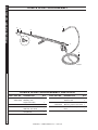


![[AUDREY] : Aujourd`hui j`ai la fatigue au bout des paupières et dans](http://vs1.manualzilla.com/store/data/006416695_1-5b32fe482acca894c306bc9e83c2e782-150x150.png)