1
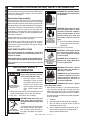
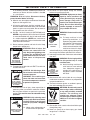
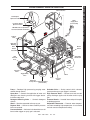
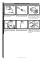
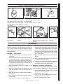
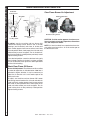
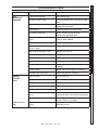
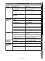
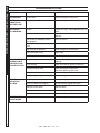
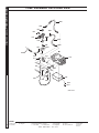
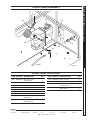
SSD
OPERATOR’S MANUAL
98011940-1
LIS T E D
MODEL #
SSD-603567E
ORDER #
1.110-586.0
SSD-603567E/G
1.110-587.0
®
To locate your local Shark Commercial Pressure Washer Dealer nearest you,
visit www.sharkpw.com
9.801-194.0
CONTENTS
Introduction & Important Safety Information
4-6
Component Identification
7
Assembly Instruction
8
Operating Instructions
9
Detergents & Cleaning Tips
10
Shut Down & Clean-Up
11
Storage11
Maintenance12-14
Troubleshooting15-18
Preventative Maintenance & Oil Change Chart 19
Exploded View
20-21
Exploded View, Parts List
22-24
Hose and Spray Gun Assembly & Parts List
25
Platform, Isolator, Exploded View & Parts List
26-27
Pump Assemblies, Exploded View
28
Pump Assemblies, Parts List
29
Control Box, Exploded View & Parts List
30
Float Tank Assembly, Exploded View & Parts List
31
Specifications32
VRT 3 Unloader Exploded View & Parts List
33
ST.1 Series Pump Exploded View & Parts List
34-35
Clear Flame Burner "S" Replacement & Parts List
36-37
Clear Flame Burner "M/L" Replacement & Parts List
38-39
Model Number ______________________________
Serial Number ______________________________
Date of Purchase ____________________________
The model and serial numbers will be found on a decal attached
to the pressure washer. You should record both serial number and
date of purchase and keep in a safe place for future reference.
3
SSD • 9.801-194.0 • Rev. 2/14
PRESSURE WASHER
OPERATOR’S MANUAL
INTRODUCTION & IMPORTANT SAFETY INFORMATION
Owner/User Responsibility:
The owner and/or user must have an understanding of
the manufacturer’s operating instructions and warnings
before using this pressure washer. Warning information
should be emphasized and understood. If the operator
is not fluent in English, the manufacturer’s instructions
and warnings shall be read to and discussed with
the operator in the operator’s native language by the
purchaser/owner, making sure that the operator comprehends its contents.
EAR PROTECTION
MUST BE WORN
WARNING
Owner and/or user must study and maintain for future
reference the manufacturers’ instructions.
The operator must know how to stop the machine
quickly and understand the operation of all controls.
Never permit anyone to operate the engine without
proper instructions.
SAVE THESE INSTRUCTIONS
When ordering parts, please specify model and serial number. Use only identical replacement parts.
This machine is to be used only by trained
operators.
IMPORTANT SAFETY
INFORMATION
WARNING: To reduce the risk of
injury, read operating instructions carefully before using.
1. Read the owner's manual
thoroughly. Failure to follow
instructions could cause malfunction of the machine and
READ OPERATOR’S
MANUAL THOROUGHLY
result in death, serious bodily
PRIOR TO USE.
injury and/or property damage.
2. Know how to stop the machine and bleed pressure
quickly. Be thoroughly familiar with the controls.
3. Stay alert — watch what you are doing.
WARNING
KEEP WATER
SPRAY AWAY FROM
ELECTRICAL WIRING.
USE PROTECTIVE
EYE WEAR
AND CLOTHING
WHEN OPERATING
THIS EQUIPMENT.
WARNING: High pressure spray
can cause paint chips or other
particles to become airborne
and fly at high speeds. To avoid
personal injury, eye, hand and
foot safety devices must be
worn.
5.Eye, hand, and foot protection
must be worn when using this
equipment.
6. Keep operating area clear of all persons.
WARNING WARNING: Flammable liquids
can create fumes which can ignite, causing property damage
or severe injury.
WARNING: Risk of explosion —
RISK OF EXPLOSION:
Operate only where open flame
OPERATE ONLY
WHERE OPEN FLAME
or torch is permitted.
OR TORCH IS
This manual should be considered a permanent
part of the machine and should remain with it if
machine is resold.
4
WARNING WARNING:This machine exceeds
85 db appropriate ear protection
must be worn.
Thank you for purchasing a Shark Pressure Washer. We
reserve the right to make changes at any time without
incurring any obligation.
WARNING: Keep wand, hose, and
water spray away from electric
wiring or fatal electric shock may
result.
4. All installations must comply with
local codes. Contact your electrician, plumber, utility company or
the selling distributor for specific
details.
PERMITTED
WARNING
RISK OF FIRE.
DO NOT ADD FUEL
WHEN OPERATING
MACHINE.
WARNING: Risk of fire — Do not
add fuel when the product is
operating or still hot.
WARNING: Do not use gasoline
crankcase draining or oil containing gasoline, solvents or
alcohol. Doing so will result in
fire and/or explosion.
WARNING: Risk of fire — Do not
Spray flammable liquids.
7. Allow engine to cool for 1-2 minutes before refueling. If any fuel is spilled, make sure the area is dry
before testing the spark plug or starting the engine.
(Fire and/or explosion may occur if this is not done.)
Gasoline engines on mobile or portable equipment
shall be refueled:
a. outdoors;
b. with the engine on the equipment stopped;
c. with no source of ignition within 10 feet of
the dispensing point; and
d. with an allowance made for expansion of the fuel should the equipment be exposed to a higher ambient temperature.
SSD • 9.801-194.0 • Rev. 2/14
In an overfilling situation, additional precautions are
necessary to ensure that the situation is handled
in a safe manner.
WARNING: Risk of injury. Disconnect battery
ground terminal before servicing.
8. When in use , do not place machine near flammable
objects as the engine is hot.
9.Oil burning appliances shall be installed only in
locations where combustible dusts and flammable
gases or vapors are not present. Do not store or
use gasoline near this machine.
10. Use No. 1 or No. 2 heating oil (ASTM D306) only.
NEVER use gasoline in your fuel oil tank. Gasoline
is more combustible than fuel oil and could result
in a serious explosion. NEVER use crankcase or
waste oil in your burner. Fuel unit malfunction could
result from contamination.
11. Do not confuse gasoline and fuel oil tanks. Keep
proper fuel in proper tank.
WARNING
RISK OF INJURY.
HOT SURFACES
CAN CAUSE BURNS
WARNING: Risk of injury. Hot
surfaces can cause burns. Use
only designated gripping areas
of spray gun and wand. Do not
place hands or feet on non-insulated areas of the pressure
washer.
12. Transport/repair with fuel tank EMPTY or with fuel
shut-off valve OFF.
CAUTION: Hot discharge fluid.
Do not touch or direct discharge
stream at persons.
HOT DISCHARGE
FLUID: DO NOT
TOUCH OR DIRECT
DISCHARGE STREAM
AT PERSONS.
WARNING: This machine produces hot water and must have
insulated components attached
to protect the operator.
13.To reduce the risk of injury, close supervision is
necessary when a machine is used near children.
Do not allow children to operate the pressure
washer. This machine must be attended during
operation.
WARNING
TRIGGER GUN KICKS
BACK - HOLD WITH
BOTH HANDS
WARNING: Grip cleaning wand
securely with both hands before
starting. Failure to do this could
result in injury from a whipping
wand.
14.Never make adjustments on
machine while in operation.
15.Be certain all quick coupler fittings are secured
before using pressure washer.
WARNING
RISK OF INJECTION
OR SEVERE INJURY
TO PERSONS. KEEP
CLEAR OF NOZZLE.
WARNING
WARNING: High pressure developed by these machines will
cause personal injury or equipment damage. Keep clear of
nozzle. Use caution when operating. Do not direct discharge
stream at people, or severe injury or death will result.
WARNING: Protect machine from
freezing.
16. To keep machine in best
operating conditions, it is
important you protect machine
from freezing. Failure to protect
machine from freezing
PROTECT FROM
FREEZING
could cause malfunction of the
machine and result in death,
serious bodily injury, and/or property damage. Follow storage instructions specified in this manual.
PRESSURE WASHER OPERATOR’S MANUAL
IMPORTANT SAFETY INFORMATION
17. Inlet water must be clean fresh water and no hotter
then 90°F.
WARNING WARNING: Risk of asphyxiation.
Use this product only in a well
ventilated area.
18. Avoid installing machines in
small areas or near exhaust
fans. Adequate oxygen is
RISK OF
needed for combustion or
ASPHYXIATION: USE
THIS PRODUCT ONLY
dangerous carbon monoxide
IN A WELL
will result.
VENTILATED AREA.
19.Manufacturer will not be liable for any changes
made to our standard machines or any components
not purchased from us.
20. The best insurance against an accident is precaution and knowledge of the machine.
WARNING: Be extremely careful
when using a ladder, scaffolding
or any other relatively unstable
location. The cleaning area
should have adequate slopes
and drainage to reduce the possibility of a fall due to slippery
RISK OF INJURY
surfaces.
FROM FALLS WHEN
USING LADDER.
21. Do not allow acids, caustic or abrasive fluids to pass
through the pump.
22.Never run pump dry or leave spray gun closed
longer than 1-2 minutes.
WARNING
5
SSD • 9.801-194.0 • Rev. 2/14
PRESSURE WASHER
OPERATOR’S MANUAL
IMPORTANT SAFETY INFORMATION
23.Machines with shut-off spray gun should not be
operated with the spray gun in the off position for
extensive periods of time as this may cause damage to the pump.
24. Protect discharge hose from vehicle traffic and
sharp objects. Inspect condition of high pressure
hose before using or bodily injury may result.
25. Before disconnecting discharge hose from water
outlet, turn burner off and open spray gun to allow water to cool below 100° before stopping the
machine. Then open the spray gun to relieve pressure. Failure to properly cool down or maintain the
heating coil may result in a steam explosion.
26.Do not overreach or stand on unstable support.
Keep good footing and balance at all times.
27. Do not operate this machine when fatigued or under
the influence of alcohol, prescription medications,
or drugs.
28.In oil burning models, use only kerosene, No. 1
home heating fuel, or diesel. If diesel is used, add
a soot remover to every tankful.
Follow the maintenance instructions
specified in the manual.
6
SSD • 9.801-194.0 • Rev. 2/14
Inlet Connection
Flue Adapter
Optional 7-10049
Water
Supply Hose
(not included)
Insulation Gasket
Optional 7-01471
NOTE: Burner air adjustment
must be tested after installation.
Rupture
Disk
Detergent
Metering
Valve
PRESSURE WASHER OPERATOR’S MANUAL
COMPONENT IDENTIFICATION
Burner
Switch
Diesel
Fuel Tank
Spray
Gun
Adjustable
Thermostat
High
Pressure
Hose
Pressure
Nozzle
98011940-2
Unloader
Valve
Trigger/Safety
Latch
Wand
Pump
Detergent
Pick-up Hose Detergent Bucket
(not included)
Pressure
Switch
Pump — Develops high pressure by pumping water
volume through nozzle.
Unloader Valve — Safety control which releases
pressure when spray gun trigger is released.
Spray Gun — Controls the application of water and
detergent onto cleaning surface with trigger device.
Includes safety latch.
High Pressure Hose — Connect one end to water
pump discharge nipple and the other end to spray
gun.
Detergent Metering Valve — Controls detergent
mixture.
Pressure Nozzle — Inserted into wand quick coupler
to develop pressure
Wand — Must be connected to the spray gun.
Adjustable Thermostat — Prevents water temperature from exceeding high temperatures. Is not used to
maintain constant temperature setting.
Rupture Disk — Will burst when extreme pressure
limits are reached.
Pressure Switch — Activates fuel solenoid to turn off
burner when trigger on spray gun is released.
SSD • 9.801-194.0 • Rev. 2/14
7
PRESSURE WASHER
OPERATOR’S MANUAL
ASSEMBLY INSTRUCTIONS
Pressure
Nozzle
Spray
Gun
Dipstick
Safety
Latch
Wand
High
Pressure
Hose
98011940-11
98011940-12
98011940-10
STEP 1: Attach the high pressure
hose to the spray gun using teflon
tape on hose threads.
STEP 2: Pull the spring-loaded
collar of the wand coupler back to insert your choice of pressure nozzle.
Garden
Hose
Pump
Discharge
Fitting
98011940-13
STEP 4: Connect the high pressure
hose to the pump discharge fitting.
Push coupler collar forward until
secure.
STEP 3: Remove shipping cap and
install oil dipstick. Check pump oil
level by using dipstick or observe
oil level in oil window (if equipped).
Use 30 wt. non detergent oil.
Water
Inlet
98011940-15
98011940-14
STEP 5: Connect garden hose to
cold water source and turn water on
completely. Never use hot water.
8
SSD • 9.801-194.0 • Rev. 2/14
STEP 6: Connect the garden hose
to pump water inlet. Inspect inlets.
CAUTION: Do not run the pump
without water or pump damage
will result.
Oil Dipstick
PRESSURE WASHER
OPERATING INSTRUCTIONS
Fuel
Tank
Oil Cap Filter
98011940-17
STEP 1: Read operator's manual before operating machine. Check engine
oil level. Oil level should be level with the bottom of the oil filler neck. (Refer
to the engine’s operating manual included with machine.) We recommend
that the oil be changed after the first 50 hours of use, then once every
250 hours. NOTE: Improper oil levels will cause low oil sensor to shut off
engine. IMPORTANT! Do not run engine with high or low oil levels
as this will cause engine damage.
STEP 2: Fill engine fuel tank with
No. 2 diesel fuel. Check engine and
pump oil levels. Check engine radiator fluid level. Install battery and
connect red cable to the + terminal
and black to the - terminal.
OPERATOR’S MANUAL
98011940-16
Trigger
Key
Switch
98011940-18
STEP 3: Read engine manual. The
keyed ignition is located on the engine control panel. Turn key to first
position. The glow plug light will illuminate. When the light goes out, turn
key to start (second) position. Do not
hold key in start position longer than
five (5) seconds or starter motor will
be damaged.
98011940-20
98011940-19
STEP 4: Before installing pressure nozzle, trigger spray gun to
eliminate trapped pressure. Then
run machine allowing water to flush
through the system until clear.
Safety
Latch
STEP 5: With spray gun and wand
pointed away from you or anybody
else, insert pressure nozzle into
quick coupler on end of wand.
Press trigger on spray gun to obtain
pressurized cold water spray.
WARNING! Never replace nozzles without engaging the safety
latch on the spray gun trigger.
Detergent
Valve
Burner
Switch
98011940-18
STEP 6: For hot water, turn the
burner switch to ON when a steady
stream of water flows out of the
spray gun. Burner will light automatically.
98011940-21
STEP 7: To apply detergent, place
detergent pick-up tube into a container of detergent and turn the
detergent valve counterclockwise.
NOTE: Do not start machine with
burner switch on.
Burner
Switch
98011940-18
STEP 8: To stop, reverse steps
and set all controls to their original
settings.
Turn burner switch OFF and open
trigger on spray gun, allowing water
to cool.
9
SSD • 9.801-194.0 • Rev. 2/14
WARNING
OPERATOR’S MANUAL
PRESSURE WASHER
DETERGENTS & GENERAL CLEANING TECHNIQUES
98011940-22
WARNING: Some detergents
may be harmful if inhaled or ingested, causing severe nausea,
fainting or poisoning. The harmful elements may cause property
damage or severe injury.
STEP 1: Use detergent designed
specifically for pressure washers.
Household detergents could damage the pump. Prepare detergent
solution as required by the manufacturer. Fill a container with pressure washer detergent. Place the
filter end of detergent suction tube
into the detergent container.
STEP 2: Open detergent valve to desired mixture ratio.
STEP 3: With the engine running, pull trigger to oper-
THERMAL PUMP PROTECTION
If you run the engine on your pressure washer for 3-5
minutes without pressing the trigger on the spray gun,
circulating water in the pump can reach high temperatures. When the water reaches this temperature,
the pump protector engages and cools the pump by
discharging the warm water onto the ground. This
thermal device prevents internal damage to the pump.
CLEANING TIPS
Pre-rinse cleaning surface with fresh water. Place
detergent suction tube directly into cleaning solution
and apply to surface (for best results, limit your work
area to sections approximately 6 feet square and always
apply detergent from bottom to top). Allow detergent
to remain on surface 1-3 minutes. Do not allow detergent to dry on surface. If surface appears to be drying,
simply wet down surface with fresh water. If needed,
use brush to remove stubborn dirt. Rinse from top to
bottom in an even sweeping motion keeping the spray
nozzle approximately 1 foot from cleaning surface. Use
overlapping strokes as you clean and rinse any surface.
For best surface cleaning action spray at a slight angle.
Recommendations:
Detergent
Valve
98011940-23
ate machine. Liquid detergent is
drawn into the machine and mixed
with water. Apply detergent to
work area. Do not allow detergent
to dry on surface.
I M P O R TA N T : Yo u m u s t
flush the detergent line after each use by placing the
suction tube into a bucket of clean water, then run the
pressure washer for 1-2 minutes.
98011940-19
• Before cleaning any surface, an inconspicuous
area should be cleaned to test spray pattern and
distance for maximum cleaning results.
• If painted surfaces are peeling or chipping, use
extreme caution as pressure washer may remove
the loose paint from the surface.
• Keep the spray nozzle a safe distance from the surface you plan to clean. High pressure wash a
small area, then check the surface for damage.
If no damage is found, continue to pressure
washing.
CAUTION - Never use:
• Bleach, chlorine products and other corrosive
chemicals
• Liquids containing solvents (i.e., paint thinner,
gasoline, oils
• Tri-sodium phosphate products
• Ammonia products
• Acid-based products
These chemicals will harm the machine and will damage the surface being cleaned.
RINSING
It will take a few seconds for the detergent to clear.
Apply safety latch to spray gun. Open detergent valve.
Select and install the desired high pressure nozzle.
NOTE: You can also stop detergent from flowing by
simply removing detergent siphon tube from bottle.
10
SSD • 9.801-194.0 • Rev. 2/14
Burner
Switch
98011940-24
Water
Inlet
98011940-18
98011940-25
STEP 2: Turn burner switch off and
continue spraying, allowing water to
cool below 100°F.
STEP 3: Turn off water supply.
To stop engine, turn key to off
position.
High
Pressure
Outlet
Garden
Inlet
98011940-19
Safety
Latch
98011940-20
98011940-15
STEP 4: Press trigger to release water pressure.
OPERATOR’S MANUAL
STEP 1: Remove detergent suction
tube from container and insert into
one gallon of fresh water. Open
detergent mixing valve. Pull trigger
on spray gun and siphon water for
one minute.
On-Off
Key Switch
PRESSURE WASHER
SHUTTING DOWN AND CLEAN-UP
STEP 5: Disconnect the garden
hose from the water inlet on the
machine.
98011940-26
STEP 6: Disconnect the high
pressure hose from high
pressure outlet. Protect from
freezing.
STEP 7: Engage
the spray gun
safety lock.
STORAGE
Measures should be taken to protect your FOCS series
engine if the engine is not operated for a period of 30
days or more. Proper storage will protect the engine
from corrosion and prevent costly repairs due to storage
induced problems.
Storage - 1 to 6 months
1. Start and idle the engine at a no-load condition for
15 minutes.
2. Stop the engine, allow the engine to cool enough
to safely drain the oil as shown Re-install the oil
drain plug, then fill the crankcase with MIL-L-644P9 protectant oil. Fill the fuel tank with a high grade
fuel preservative (add mix) such as STA-BIL per the
manufacturer recommendations.
3. Start and operate the engine at 3/4 speed for 5-10
minutes.
4.Stop the engine, allow to cool enough to safely
drain the engine oil as shown. Re-install the oil
drain plug.
5.Refill the engine with standard recommended lubricating oil.
6. Drain the fuel tank. Remove the fuel filter. Install a
new fuel filter.
7. Carefully clean all debris from the radiator fins.
8.Remove the intake manifold. Rotate the engine
until the intake valve opens at each cylinder. Using
suitable means, pour approximately 1 tsp. of engine
oil into each cylinder. Rotate the engine several
revolutions. Spray the inside of the intake manifold
with SAE 10 W oil. Replace the intake manifold
using a new gasket.
9. Spray the inside of the exhaust manifold with SAE
10W oil.
10. Cover all openings with tape and apply grease to
any and all unpainted surfaces.
11. Loosen the fan belt before wrapping the engine in
plastic film and storing in a dry place away from
high voltage sources and off the ground.
Storage - In excess of 6 months
Perform the storage preparation procedures approximately as detailed, except with the following changes.
1. Replace the oil in step 2 above with MIL-L-21260,
grade 2, SAE 30W rustproof oil.
2. Delete steps 5 and 11 above.
3.Coat any and all unpainted surfaces with MIL-C
16173D, grade 3 anti-rust grease.
4. Replace anti-freeze every 2 years.
SSD • 9.801-194.0 • Rev. 2/14
11
PRESSURE WASHER
OPERATOR’S MANUAL
MAINTENANCE
PREVENTATIVE MAINTENANCE
1.Check to see that water pump is properly
lubricated.
2.Follow winterizing instructions to prevent freeze
damage to pump and coils.
3. Always neutralize and flush detergent from system
after use.
4. If water is known to have high mineral content, use
a water softener in your water system, or de-scale
as needed.
5. Do not allow acidic, caustic or abrasive fluids to be
pumped through system.
6. Always use high grade quality cleaning products.
7. Never run pump dry for extended periods of time.
8. Use clean No. 2 diesel fuel. Clean or replace fuel
filter every 250 hours of operation. Avoid water
contaminated fuel as it will damage the fuel pump.
9. If machine is operated with smoky or eye burning
exhaust, coils will soot up. Adjust air bands and fuel
pressure for proper emission.
10.Never allow water to be sprayed on or near
the engine or burner assembly or any electrical
component.
11. Periodically delime coils as per instructions.
12. Check to see that engine is properly lubricated. Use
SAE 10W40 grade oil.
It is advisable, periodically, to visually inspect the
burner. Check air inlet to make sure it is not clogged
or blocked. Wipe off any oil spills and keep equipment
clean and dry.
Winterizing Procedure:
Damage due to freezing is not covered by warranty.
Adhere to the following cold weather procedures whenever the washer must be stored or operated outdoors
under freezing conditions.
During winter months, when temperatures drop below
32°F, protecting your machine against freezing is necessary. Store the machine in a heated room. If this is not
possible then mix a 50/50 solution of anti-freeze and
water in the float tank. Turn the engine on to siphon the
anti-freeze mixture through the machine. If compressed
air is available, an air fitting can be screwed into the
float tank by removing the float tank strainer and fitting.
Then inject the compressed air. Water will be blown
out of the machine when the trigger on the spray gun
is opened.
High Limit Hot Water Thermostat:
For safety, each machine is equipped with a temperature sensitive high limit control switch. In the event that
the water should exceed its operating temperature,
the high limit control will turn the burner off until the
water cools, then it will automatically reset itself. The
thermostat sensor is located on the discharge side of
the heating coil. The thermostat control dial is located
on the control panel.
Pumps:
Use only SAE 10/40 weight non-detergent oil. Change
oil after first 50 hours of use. Thereafter, change oil
every three months or at 500 hour intervals. Oil level
should be checked through use of dipstick found on top
of pump, or the red dot visible through the oil gauge
window. Oil should be maintained at that level.
The flow of combustion and ventilating air to the burner
must not be blocked or obstructed in any manner.
The area around the washer should be kept clean
and free of combustible materials, gasoline and other
flammable vapors and liquids.
MAINTENANCE AND SERVICE
Unloader Valves:
Unloader valves are preset and tested at the factory
before shipping. Occasional adjustment of the unloader
may be necessary to maintain correct pressure.
Adjusting Unloader Valves:
Tampering with the factory setting may cause
personal injury and/or property damage and will void
the manufacturer's warranty.
12
SSD • 9.801-194.0 • Rev. 2/14
Deliming Coils:
Periodic flushing of coils or optional float tank is
recommended.
Step 1 Fill a container with 4 gallons of water, then ..
add 1 lb. of deliming powder. Mix thoroughly. .
Pour mixture into float tank.
Step 2 Remove wand assembly from spray gun and .
put spray gun into float tank. Secure the trig-.
ger on the spray gun into the open position.
Step 3 Turn engine on, allowing solution to be
pumped through coils back into the float tank.
The solution should be allowed to circulate 2- 4
hours or until the color changes.
Step 4 After circulating solution, flush the entire
system with fresh water. Clean out float tank
and then reinstall wand assembly to spray gun.
Periodic inspection, to insure that the fuel solenoid
valve functions properly, is recommended. This can
be done by operating the machine and checking to
see that the burner is not firing when the spray gun is
in the OFF position.
Fuel Pressure Adjustment:
To control water temperature, adjust fuel pressure
by turning the regulating pressure adjusting screw
clockwise to increase, counterclockwise to decrease.
NOTE: When changing fuel pump, a bypass plug must
be installed in return port or fuel pump will not prime.
Burner Nozzle:
Keep the tip free of surface deposits by wiping it with
a clean, solvent saturated cloth, being careful not to
plug or enlarge the nozzle. For maximum efficiency,
replace the nozzle each season.
PRESSURE WASHER OPERATOR’S MANUAL
MAINTENANCE AND SERVICE
Removal of Soot from Heating Coil:
In the heating process, fuel residue in the form of soot
deposits may develop between the heating coil pipe,
and block air flow which will affect burner combustion.
When soot has been detected on visual observation,
the soot on the coil must be washed off after following
the coil removal steps (See Coil Removal section).
Electrode Setting:
Electrodes
98011930-28
Gap
1/8"
1/8"
3/8"
Fuel:
Use clean fuel oil that is not contaminated with water
and debris. Replace fuel filter and drain tank every 100
hours of operation.
Use No.1 or No 2 Heating Oil (ASTM D306) only.
NEVER use gasoline in your burner fuel tank. Gasoline
is more combustible than fuel oil and could result in a
serious explosion. NEVER use crankcase or waste oil
in your burner. Fuel unit malfunction could result from
contamination.
Fuel Control System:
This machine utilizes a fuel solenoid valve located on
the fuel pump to control the flow of fuel to the combustion chamber. The solenoid, which is normally closed,
is activated by a flow switch when water flows through
it. When the operator releases the trigger on the spray
gun, the flow of water through the flow switch stops,
turning off the electrical current to the fuel solenoid.
The solenoid then closes, shutting off the supply of
fuel to the combustion chamber. Controlling the flow
of fuel in this way gives an instantaneous burn-or-noburn situation, thereby eliminating high and low water
temperatures and the combustion smoke normally
associated with machines incorporating a spray gun.
3/16"
2-7/8"
1/2"
Nozzle
Adapter
Top View
Side View
Periodically Check Wiring Connections. If Necessary
To Adjust Electrodes, Use Diagram.
Beckett Burner Air Adjustment:
The oil burner on this machine is preset for operation
at altitudes below 1000 feet. If operated at higher
altitudes, it may be necessary to adjust the air band
setting. Adjust air band for a #1 or #2 smoke spot
on the Bacharach scale. If a smoky or eye-burning
exhaust is being emitted from the stack, two things
should be checked. First, check the fuel to be certain
that kerosene or No.1 home heating fuel is being used.
Next, check the air adjustment on the burner. An oily,
smoky fire indicates a lack of air and the air band
should be moved to allow the air to flow through the
burner. Sharp eye-burning fumes indicate too much
air flowing through the combustion chamber. The air
band should be readjusted to allow less air to flow
through the burner.
13
SSD • 9.801-194.0 • Rev. 2/14
PRESSURE WASHER
OPERATOR’S MANUAL
MAINTENANCE AND SERVICE
Clear Flame Burner Air Adjustment
Air Shutter
Locking Screw
Air Shutter
Reference Numbers
Air Band
Air Band
Air Band Locking Screws
Air Shutter
Locking Screw
Air Band Locking
Screw
To adjust, start the machine and turn burner ON.
Loosen two locking screws found in the air shutter
openings (see illustration) and close air shutter until
black smoke appears from burner exhaust vent. Note
air band position. Next, slowly open the air shutter until
white smoke just starts to appear. Turn air shutter halfway back to the black smoke position previously noted.
Tighten locking screws.
CAUTION: If white smoke appears from burner exhaust vent during start-up or operation, discontinue
use and readjust air bands.
NOTE: If a flue is installed, have a professional serviceman adjust your burner for a #1 or #2 smoke spot on
the Bacharach scale.
If the desired position cannot be obtained using only
the air shutter, lock the air shutter in as close a position
as can be obtained, then repeat the above procedure
on the air band setting.
Shark Clear Flame Oil Burner
Burner Air Adjustment: The oil burner on this machine
is preset for operation at altitudes below 1000 feet. If
operated at higher altitudes, it may be necessary to
adjust the air band for a #1 or #2 smoke spot on the
Bacharach scale.
To adjust, start machine and turn burner ON. Loosen
two locking screws found on the air band and close air
band until black smoke appears from burner exhaust
vent. Note air band position. Next, slowly open the air
band until white smoke just starts to appear. Turn air
band halfway back to the previously noted position.
Tighten locking screws.
14
SSD • 9.801-194.0 • Rev. 2/14
PROBLEM
POSSIBLE CAUSE
SOLUTION
LOW
OPERATING
PRESSURE
Faulty pressure gauge
Install new gauge.
Insufficient water supply
Use larger supply hose; clean filter at water
inlet.
Old, worn or incorrect spray nozzle
Match nozzle number to machine and/or
replace with new nozzle.
Belt slippage
Tighten or replace; use correct belt.
Plumbing or hose leak
Check plumbing system for leaks.
Retape leaks with teflon tape.
Faulty or misadjusted unloader
valve
Adjust unloader for proper pressure. Install
repair kit when needed.
Worn packing in pump
Install new packing kit.
Fouled or dirty inlet or discharge
valves in pump
Clean inlet and discharge valves.
Worn inlet or discharge valves
Replace with valve kit.
Obstruction in spray nozzle
Remove obstruction.
Leaking pressure control valve
Rebuild or replace as needed.
Slow engine RPM
Set engine speed at proper specifications.
Pump sucking air
Check water supply and possibility of air
seepage.
Valves sticking
Check and clean or replace if necessary.
Unloader valve seat faulty
Check and replace if necessary.
Little or no fuel
Fill tank with fuel.
Improper fuel or water in fuel
Drain fuel tank and fill with proper fuel.
Clogged fuel line
Clean or replace.
Plugged fuel filter
Replace as needed.
Misadjusted burner air bands
Readjust air bands for clean burn.
Little or no fuel pressure from fuel
pump
Increase fuel pressure to specification and/or
replace fuel pump. Test with pressure gauge.
Faulty burner transformer
Test transformer for proper arc between
contacts. Replace as needed.
Disconnected or short in electrical
wiring
All wire contacts should be clean and tight.
No breaks in wire.
BURNER
WILL NOT
LIGHT
(continued on next
page)
PRESSURE WASHER Troubleshooting Guide
TROUBLESHOOTING
15
SSD • 9.801-194.0 • Rev. 2/14
PRESSURE WASHER Troubleshooting Guide
TROUBLESHOOTING
PROBLEM
POSSIBLE CAUSE
SOLUTION
BURNER WILL
NOT LIGHT
(continued from
previous page)
Flex coupling slipping on fuel
pump shaft or burner motor shaft
Replace if needed.
On-Off switch defective
Check for electrical current reaching burner
assembly with burner switch on.
Heavy sooting on coil and burner
can cause interruption of air flow
and shorting of electrodes
Clean as required.
Improper electrode setting
Check and reset according to diagram in
Operator’s Manual.
Fuel not reaching combustion
chamber
Check fuel pump for proper flow. Check
solenoid flow switch on machines with spray
gun control, for proper on-off fuel flow control.
Clogged burner nozzle
Clean as required.
Thermostat faulty or slow engine
speed
Increase engine RPM to increase voltage.
Flow switch malfunction
Remove, test for continuity and replace as needed.
Flow solenoid malfunction
Replace if needed.
Valves worn
Check and replace if necessary.
Blockage in valve
Check and replace if necessary.
Pump sucking air
Check water supply and air seepage at joints in
suction line.
Worn piston packing
Check and replace if necessary.
Gasoline engine altitude
The gasoline engine is preset for operation
at altitudes below 1000 feet above sea level.
If operated at higher altitudes, it may be necessary
to install a high altitude main jet in the carburetor.
Contact your local authorized engine sales
and service center for details.
Improper fuel or water in fuel
Drain tank and replace contaminated fuel.
Improper air adjustment
Readjust air bands on burner assembly.
Low fuel pressure
Adjust fuel pump pressure to specifications.
Plugged or dirty burner nozzle
Replace nozzle.
Faulty burner nozzle spray
pattern
Replace nozzle.
Heavy accumulation of soot on
coils and burner assembly
Remove coils and burner assembly, clean
thoroughly.
Misaligned electrode setting
Realign electrodes to specifications.
Obstruction in smoke stack
Check for insulation blockage or other foreign
objects.
Low engine RPM
Increase RPM.
FLUCTUATING
PRESSURE
MACHINE
SMOKES
16
SSD • 9.801-194.0 • Rev. 2/14
PROBLEM
POSSIBLE CAUSE
SOLUTION
LOW WATER
TEMPERATURE
Improper fuel or water in fuel
Replace with clean and proper fuel.
Low fuel pressure
Increase fuel pressure.
Weak fuel pump
Check fuel pump pressure. Replace pump if
needed.
Fuel filter partially clogged
Replace as needed.
Soot build-up on coils not allowing
heat transfer
Clean coils.
Improper burner nozzle
Call Dealer.
Incoming water to machine warm
or hot
Lower incoming water temperature.
Fuel pump pressure too high
See specifications for proper fuel pressure.
Fuel pump defective
Replace fuel pump.
Detergent line sucking air
Tighten all clamps. Check detergent lines for
holes.
Defective temperature switch
Replace.
Incorrect fuel nozzle size
Call Dealer.
Insufficient water supplied
Check water G.P.M. to machine.
Restricted water flow
Check nozzle for obstruction, proper size.
Air in suction line
Check water supply and connections on
suction line.
Broken or weak inlet or discharge
valve springs
Check and replace if necessary.
Excessive matter in valves
Check and clean if necessary.
Worn bearings
Check and replace if necessary.
PRESENCE OF
WATER IN OIL
Oil seal worn
Check and replace if necessary.
High humidity in air
Check and change oil twice as often.
WATER DRIPPING
FROM UNDER
PUMP
Piston packing worn
Check and replace if necessary.
O-Ring plunger retainer worn
Check and replace if necessary.
Cracked piston
Check and replace if necessary.
Pump protector
Lower water supply pressure. Do not run
with spray gun closed longer than 2 minutes.
WATER
TEMPERATURE
TOO HOT
PUMP NOISY
PRESSURE WASHER Troubleshooting Guide
TROUBLESHOOTING
17
SSD • 9.801-194.0 • Rev. 2/14
PRESSURE WASHER Troubleshooting Guide
TROUBLESHOOTING
PROBLEM
POSSIBLE CAUSE
SOLUTION
OIL DRIPPING
Oil seal worn
Check and replace if necessary.
EXCESSIVE
VIBRATION IN
DELIVERY LINE
Irregular functioning of the valves
Check and replace if necessary.
DETERGENT
NOT DRAWING
Air leak
Tighten all clamps. Check detergent lines for
holes.
Restrictor in float tank is missing
Replace restrictor. Check for proper orifice in
restrictor.
Filter screen on detergent suction
hose plugged
Clean or replace.
Dried up detergent plugging metering
valve
Disassemble and clean thoroughly.
High viscosity of detergent
Dilute detergent to specifications.
Hole in detergent line(s)
Repair hole.
Low detergent level
Add detergent, if needed.
Pump sucking air
Check water supply and possibility of air
seepage.
Valves sticking
Check and clean or replace if necessary.
Nozzle incorrectly sized
Check and replace if necessary
(See serial plate for proper size).
Unloader valve seat faulty
Check and replace if necessary.
Worn piston packing
Check and replace if necessary.
Fuel pump seized
Replace fuel pump.
Burner fan loose or misaligned
Position correctly, tighten set screw.
Defective control switch
Replace switch.
Loose wire
Check and replace or tighten wiring.
Defective burner motor
Replace motor.
Relief valve defective
Replace or repair.
PUMP RUNNING
NORMALLY BUT
PRESSURE LOW
ON INSTALLATION
BURNER
MOTOR WILL
NOT RUN
RELIEF VALVE
LEAKS WATER
18
SSD • 9.801-194.0 • Rev. 2/14
This pressure washer was produced with the best available materials and quality craftsmanship. However, you
as the owner have certain responsibilities for the correct care of the equipment. Attention to regular preventative
maintenance procedures will assist in preserving the performance of your equipment. Contact your dealer for
maintenance. Regular preventative maintenance will add many hours to the life of your pressure washer. Perform
maintenance more often under severe conditions.
Check pump oil level before first use of your new pressure washer. Change pump oil after first 50 hours and
every 3 months or 500 hours thereafter. Use SAE 30 weight oil, non-detergent.
Date Oil Changed
Month/Day/Year
No. of Operating Hours
Since Last Oil Change
Brand Name and
Type of Oil (see above)
PRESSURE WASHER OPERATOR’S MANUAL
PREVENTATIVE MAINTENANCE
MAINTENANCE
Maintenance Operation
Check Oil
Change Oil
Every 8 Hrs
25 Hrs
50 Hrs
or Daily
or Weekly or Monthly
Pump
Engine
100 Hrs
or Yearly
X
X
Pump
X
Engine
Air Cleaner
X
Check
Clean
Spark Plug
X
Check Valve Clearance
X
Fuel Tank Filter
Water Filter/Clean
Yearly
X
Check
X
19
SSD • 9.801-194.0 • Rev. 2/14
PRESSURE WASHER
EXPLODED VIEW
B04
B05
P31
G03
G02
G32
G30,
G31
P32
B01
B03
P30
E05
OPERATOR’S MANUAL
G00
E04
B00
L06
L05
L08
L04
B02
L00
(Reversed
View Of
Label)
L06
L02
L01
L05
R101
R103
R070
X05
L03
X01
X00
R100
R071
X03
R105
X04
R104
R106
R107
For
Detail See
Platform
Isolator
Illus.
X03
F00
X02
For
Detail See
Float Tank
Illus.
H050
H051
H052
98011940-3
LEGEND
20
G = Generator
R = Controls
E = Engine
N = Final Assembly
L = Fuel Tank
F = Frame
X = Battery Box
T = Float Tank
B = Beltguard
H = Hose
SSD • 9.801-194.0 • Rev. 2/14
W= Power Platform
U = Unloader
P = Pump
C = Coil
C301
R102
C23
C21
C40
C22
C17
C33
C34
C02
C00
C16
C30
C31
C32
C18
E26
E002
H100,H101
C15
Fuel Lines
To Burner
H110,H111
E28
C19
C20
H023,H024,
H025
C19
E00
H010,H011,
H020,H021,H022
C09
E03
E02
E20,E21,
E22 E23,
E24,E25
E251,E252
C01
C-41 C11
C04
E14
C-35
C36
C20
C08
Fuel Lines To
Fuel Tank
C-10
C-37
C-39
C07
E09,E10,E11,
E12, E13
C05
H060
R030
C-38
For
Detail
See Pump
Assy.
llus.
H090
U021
L
TRO
ATURE
ET
NERLEUR
BUROR/BRU
RES
TEMPER
CON
DE
RE LE
/ CONTRO
ATU
TURA
PER
TEMERA
DE
235
TEML
270
200
CONTRO
300
165
QUEMAD
O
130
OFF
95
APAGAR
F°
10-02033
OFF
G10,G11,
G12,G13
H030
For
Detail See
Control
Box
Illus.
E17
E16
H080
I
ER
METRE
MET
R / CHRONO
ON R
PRENDE
TRO
HOU
HOROME
R016
R017
W00
To Float
Tank
P082
P091,
P092,P093
E18
P25, P26,
P27
U022
H071
P081
E19
G25,G26,G27
C31
PRESSURE WASHER OPERATOR’S MANUAL
EXPLODED VIEW
R018
R017
H040,
H041
H081
H070
H071
U023
98011940-4
E02
E01
21
SSD • 9.801-194.0 • Rev. 2/14
PRESSURE WASHER
OPERATOR’S MANUAL
EXPLODED VIEW PARTS LIST
ITEM PART NO. DESCRIPTION
QTY
B00 9.803-023.0 Belt Guard, Diesel, Black
(587)
1
9.803-024.0 Belt Guard, 12VDC Diesel
(586)
1
B01 9.802-779.0 Nut, 3/8" ESNA, NC
3
B02 9.802-807.0 Washer, 3/8", SAE, Flat
3
B03 9.802-067.0 Bumper Pad, Engine
2
B04 9.800-006.0 Label, Hot/Caliente
w/Arrows Warning
1
B05 9.800-007.0 Label, Warning-Exposed
Pulleys
1
C00 9.803-014.0 Coil, Rodless
1
C01 9.802-013.0 Nipple, 1/2" x 2-1/2",
Galvanized SCH 80
1
C02 8.752-113.0 Adapter, 1/4"
1
C04 8.706-141.0 Coupling, 1/2" 1
C05 9.802-039.0 Elbow, 1/2" JIC x 3/8" MPT
1
C07 9.149-003.0 Discharge, Manifold
1
C08 9.802-014.0 Nipple, 1/2" x 3" Sch80
1
C09 9.802-171.0 Nipple, 3/8" x 3/8" NPT, Male
1
C10 8.933-006.0 Switch, MV60
1
C11 8.706-944.0 Hose Barb, 3/8" Barb, ML Pipe1
C15 9.803-006.0 Weldment, Bottom Wrap
1
C16 9.802-896.0 Insulation, Blanket, No Foil
ITEM PART NO. DESCRIPTION
QTY
C37 9.184-030.0 Spacer, Rupture Disk
1
C38 8.706-248.0 Plug, 3/8"
1
C39 9.196-012.0 Screw, 10-24 x 1/4"
1
C40 8.752-114.0 Nipple, 1/4" 1
C41 8.725-944.0 Rupture Disk 8000
1
R030 8.750-094.0 Thermostat, Adjustable 302°F 1
E00 9.802-327.0 Engine, Kohler Diesel, 27 HP 1
9.802-658.0
▲ Kit, Pressure Switch,
Oil Dual Port 1
E002 9.802-691.0 Exhaust Deflector 1
E01 9.802-725.0Bolt, 3/8" x 1-1/2", HH NC
GRD 8, Zinc
4
E02 9.802-807.0 Washer, 3/8", SAE, Flat
9
E03 9.802-779.0 Nut, 3/8" ESNA, NC
4
E04 Pulley, See Parts Specifications Pages
E05 Bushing, See Parts Specifications Pages
E051 9.802-710.0▲ Bolt, 5/16" x 1", NC HH
E10 9.802-036.0 Nipple, 1/2" JIC, 3/8" FNPT
1
E11 9.802-253.0 Hose, 1/2" Push-On
24"
E12 9.802-151.0 Swivel, 1/2" Female,
Push-On
2
1
1
E13 9.802-126.0 Plug, 1/2" JIC, Flare,
639F-8
C17 9.802-883.0 Insulation, Front Head,
No Hole
1
E14 9.802-660.0 Shaft, Lombardini
LDW602/903
1
C18 9.802-894.0 Insulation, Burner Head,
w/Hole
1
E16 9.802-203.0 Clamp, 1/2" Ro-Clip,
Kleinhuis
1
C19 9.802-899.0 Gasket, Burner Plate
2
C20 9.803-132.0 Insulation Retainer
2
E17 9.802-762.0 Screw, 10/32" x 1-1/4" RH,
SL, Black
1
C201 9.802-797.0▲ Screw, SS #10 HH Tek
8
E18 9.802-695.0 Nut, 10/32" Keps
1
C21 9.803-005.0 Top Wrap, SS
1
E19 9.802-802.0 Washer, 1/4", Flat, SAE
1
4
E20 9.802-444.0 Wire, THWN, 6 Gauge,
Red 80"
E21 9.802-444.0 Wire, THWN, 6 Gauge,
Black 70"
C211 9.802-808.0▲ Washer, 3/8", SAE, SS
C22 9.802-902.0 Insulation/Blanket, Die-Cut 28 1
C23 9.802-766.0 Screw, 3/8" x 1" HX Wash Head8
C30 Burner Assembly, See Spec's Pages
C301 9.802-519.0 Strain Relief, 1/2" Metal,
Two Screw
1
C31 6.390-126.0 Clamp, Hose, .46 -, .54 ST
4
C32 8.706-941.0 Hose Barb, 1/4" Barb x 1/4"
MPT Brass
1
C33 8.706-958.0 Hose Barb, 1/4" Barb x 1/4"
Pipe, 90° 1
C34 8.725-306.0 Filter, Fuel/H2O/Oil Separator 1
C35 9.802-024.0 Elbow, Street 1/2"x 3/8"
1
C36 8.706-207.0 Elbow, 3/8" Street
1
E22
9.802-487.0 Terminal, Ring Tongue
2
E23
9.802-487.0 Terminal, Ring Tongue
2
E24 9.802-501.0 Connector, Battery Post
E25 9.802-587.0Insulation,
Fiber Sleeving, 1/2" G = Generator
R = Controls
E = Engine
N = Final Assembly
L = Fuel Tank
F = Frame
2
42"
E251 9.802-207.0 Clamp, Round, 0.56 ID
3
E252 9.802-799.0 Screw, #14 x 1", TEK,
Black,Zinc 3
E26 9.800-011.0 Label, RPM Factory Set
1
F00 9.803-021.0 Frame Assy, 27 HP,
Diesel, Black
1
LEGEND
22
3
E09 9.802-155.0 Adapter, M18-1.5 x 3/8" FNPT 1
X = Battery Box
T = Float Tank
B = Beltguard
H = Hose
SSD • 9.801-194.0 • Rev. 2/14
W= Power Platform
U = Unloader
P = Pump
C = Coil
ITEM PART NO. DESCRIPTION
QTY
G00 9.802-527.0 Generator, 2FSM2PC-1/A,
WINC (587)
1
G01 9.802-720.0▲ Bolt, 3/8" x 1", NC HH (587) 4
ITEM PART NO. DESCRIPTION
QTY
H081 9.802-151.0 Swivel, 1/2" FJIC, Push-On
2
H090 8.918-421.0 Hose, Pressure, 3/8" x 16"
1
G02 9.802-807.0 Washer, 3/8", SAE, Flat (587) 8
H100 9.802-254.0 Hose, 1/4", Push-On,
Fuel Line
G03 9.802-779.0 Nut, 3/8", ESNA, NC (587)
19"
4
H101 9.802-200.0 Clamp, Screw #4
G10 9.803-004.0 Weldment, Pump/Gen. Rail
(587)
1
H110 9.802-254.0 Hose, 1/4”, Push-On,
Fuel Line
G11 9.802-779.0 Nut, 3/8", ESNA 3
H111 9.802-200.0 Clamp, Screw, #4
2
G12 9.802-099.0▲ Washer, Snubbing (587)
3
L00 9.803-025.0 Fuel Tank Assembly,
20 Gallon MS
1
L01
9.802-804.0 Washer, 5/16", Flat, SAE
4
L02
9.802-776.0 Nut, 5/16", ESNA, NC
4
L03
9.802-067.0 Bumper Pad, Engine
4
L04
9.802-082.0 Cap, Fuel Tank, Plastic
1
G13 9.802-814.0▲ Washer, 3/8", Lock,
Split Ring (587)
3
G25 9.802-733.0 Bolt, 3/8" x 3-1/2", TAP
(587)
1
G26 9.802-807.0 Washer, 3/8", SAE, Flat
(587)
4
G27 9.802-789.0 Nut, 3/8", Hex, NC (587)
2
G30 Pulley, See Parts Specifications Pages
G31
▲ Bushing, See Parts
Specifications Pages
G32 Belt, See Parts Specifications Pages
2
25"
L05 9.802-142.0 Hose Barb, 1/4" Barb x 1/8"
ML Pipe, 90°
3
L06 8.706-962.0 Hose Barb, 3/16" Barb x 1/8"
MPT, 90°
2
L07 9.802-124.0▲ Plug, 1/4" Countersunk
1
L08
1
8.932-960.0 Label, Diesel Fuel
G33 8.752-150.0▲ Cord, Moulded
1
P081 9.802-587.0 Insulation, Fiber Sleeving, 22" 1
E28 9.804-532.0▲ Dipstick Extended Kit
1
P082 9.802-207.0 Clamp, Round, 0.56 ID
H010 9.802-255.0 Hose, 3/16", Push-On, Fuel
Line
H011 9.802-200.0 Clamp, Screw, #4 48"
2
H020 9.802-254.0 Hose, 1/4", Push-On,
Fuel Line
40"
H021 9.802-200.0 Clamp, Screw, #4
2
H022 9.802-587.0Insulation,
Fiber Sleeving, 1/2"
30"
3
P092 9.802-099.0▲ Washer, Snubbing
3
P093 9.802-814.0▲ Washer, 3/8" Lock, Split
Ring
3
P25 9.802-733.0 Bolt, 3/8" x 3-1/2", Tap
1
P26 9.802-807.0 Washer, 3/8", SAE, Flat 4
P27 9.802-789.0▲ Nut, 3/8", Hex, NC 2
1
P30 Pulley, See Parts Specifications Pages
H024 9.802-741.0 Bolt, 8mm x 16mm
Hex Head
1
P32 Belt, See Parts Specifications Pages
H025 9.802-813.0 Washer, 5/16", Lock,
Split Ring
1
H030 8.918-429.0 Hose, 3/8" X 62",
2 Wire, Pressure
1
H040 9.802-252.0 Hose, 1/4" x 1/2",
Braided Vinyl
48"
H041 6.390-126.0 Clamp, Hose, .46 -, .54 ST
2
H050 9.802-251.0 Tube, 1/4" x 1/2", Clear Vinyl 72"
H051 9.802-200.0 Clamp, Screw, #4
1
H052 9.802-161.0 Strainer, 1/4", Brass w/Check 1
H060 8.711-785.0 Hose, 3/8", Push-on
2 ft
H070 9.802-261.0 Hose, 3/4", Push-On
48"
H071 9.802-152.0 Swivel, 3/4" SAE Female,
Push-On
H080 9.802-259.0 Hose, 1/2" Push-On
2
15"
2
P091 9.802-779.0 Bolt, 3/8", ESNA
H023 9.802-207.0 Clamp, Round, 0.56 ID
PRESSURE WASHER OPERATOR’S MANUAL
EXPLODED VIEW PARTS LIST
P31 Bushing, See Parts Specifications Pages
R016 9.802-710.0 Bolt, 5/16" x 1", NC HH
4
R017 9.802-776.0 Nut, 5/16", ESNA, NC
4
R018 9.802-804.0 Washer, 5/16", Flat, SAE
8
R070 9.802-188.0 Valve, Metering, 1/4" Hose
1
R071 9.800-039.0 Label, Detergent Valve
1
R100 9.803-020.0 Control Panel, Black
1
R101 9.802-799.0 Screw, #14 x 1", Tek,
Black, Zinc
13
R102 8.900-870.0 Label, Shark
1
R103 9.800-041.0 Label, Warning, Text
1
R104 9.800-042.0 Label, Control Panel
1
R105 9.800-049.0 Label, Manufacturer’s
Cleaning Solution
1
R106 9.802-064.0 Grommet, Rubber, Nozzle
4
R107
Nozzle, Please See Hose &
Spray Gun Assembly
23
SSD • 9.801-194.0 • Rev. 2/14
PRESSURE WASHER
OPERATOR’S MANUAL
EXPLODED VIEW PARTS LIST
ITEM PART NO. DESCRIPTION
QTY
U021 9.802-730.0 Bolt, 3/8" x 2-1/2",
Grade 5, Zinc
2
U022 9.802-807.0 Washer, 3/8", SAE, Flat
2
U023 9.802-779.0 Nut, 3/8", ESNA, NC
2
W00 9.803-022.0 Assy, Power
Platform, Diesel
1
X00 9.802-075.0 Box, Battery, M100
1
X01 9.802-701.0 Bolt, 1/4" x 1",
Hex Head
4
X02 9.802-773.0 Nut, 1/4", ESNA, NC
4
X03 9.802-802.0 Washer, 1/4", Flat, SAE
8
X04 9.802-067.0 Bumper Pad, Engine
4
X05 9.802-076.0 Plate, Battery Box,
Large, PO
1
▲ Not Shown
LEGEND
24
G = Generator
R = Controls
E = Engine
N = Final Assembly
L = Fuel Tank
F = Frame
X = Battery Box
T = Float Tank
B = Beltguard
H = Hose
SSD • 9.801-194.0 • Rev. 2/14
W= Power Platform
U = Unloader
P = Pump
C = Coil
3
4
2
1
PRESSURE WASHER OPERATOR’S MANUAL
HOSE & SPRAY GUN ASSEMBLY
98011940-9
HOSE & SPRAY GUN PARTS LIST
ITEM PART NO. DESCRIPTION
QTY
1
8.739-203.0 Hose, 3/8" x 50',
2 Wire, Tuff-Flex
1
2
8.710-384.0 Gun, ST-1500, 5000
10.4 GPM
1
3
9.803-805.0Wand
1
9.802-307.0 Nozzle, 0006, Red 1
9.802-308.0 Nozzle, 1506, Yellow
1
9.802-309.0 Nozzle, 2506, Green 1
9.802-310.0 Nozzle, 4006, White 1
4
LEGEND
G = Generator
R = Controls
E = Engine
N = Final Assembly
L = Fuel Tank
F = Frame
X = Battery Box
T = Float Tank
B = Beltguard
H = Hose
SSD • 9.801-194.0 • Rev. 2/14
W= Power Platform
U = Unloader
P = Pump
C = Coil
25
PRESSURE WASHER
PLATFORM ISOLATOR EXPLODED VIEW
W11
W06
W08
OPERATOR’S MANUAL
W10
W12
W13
W07
W05
W06
W06
W01
W09
W06
W09
W05
W06
W07
W05
W06
W08
W11
W09
W13
W14
98011940-8
LEGEND
26
G = Generator
R = Controls
E = Engine
N = Final Assembly
L = Fuel Tank
F = Frame
X = Battery Box
T = Float Tank
B = Beltguard
H = Hose
SSD • 9.801-194.0 • Rev. 2/14
W= Power Platform
U = Unloader
P = Pump
C = Coil
ITEM PART NO. DESCRIPTION
PRESSURE WASHER OPERATOR’S MANUAL
PLATFORM ISOLATOR PARTS LIST
QTY
W01 9.802-057.0 Isolator, Vibration Mount,
100L
12
W05 9.802-710.0 Bolt, 5/16" x 1", NC HH
24
W06 9.802-804.0 Washer, 5/16", Flat,
SAE
48
W07 9.802-776.0 Nut, 5/16", ESNA, NC
24
W08 9.802-730.0 Bolt, 3/8" x 2-1/2"
Grade 5 Zinc
10
W09 9.802-099.0 Washer, Snubbing
12
W10 9.802-807.0 Washer, 3/8", SAE, Flat
10
W11 9.802-779.0 Nut, 3/8", ESNA, NC
10
W12 9.802-717.0 Bolt, 5/16" x 2-1/2", NC HH
2
W13 9.802-804.0 Washer, 5/16", Flat, SAE
4
W14 9.802-776.0 Nut, 5/16", ESNA, NC
2
LEGEND
G = Generator
R = Controls
E = Engine
N = Final Assembly
L = Fuel Tank
F = Frame
X = Battery Box
T = Float Tank
B = Beltguard
H = Hose
SSD • 9.801-194.0 • Rev. 2/14
W= Power Platform
U = Unloader
P = Pump
C = Coil
27
PRESSURE WASHER
PUMP ASSEMBLY EXPLODED VIEW
H090
U051
OPERATOR’S MANUAL
U05
H081
U09
U01
U07
H080
U08
U04
U03
H030
H081
U021
U02
U031
P12
P01
P16
P11
P05
P13
P14
P04
P10
P03
P09
P013
P012
P011
98011940-5
LEGEND
28
G = Generator
R = Controls
E = Engine
N = Final Assembly F = Frame
L = Fuel Tank
X = Battery Box
T = Float Tank
B = Beltguard
SSD • 9.801-194.0 • Rev. 2/14
H = Hose
W= Power Platform
U = Unloader
P = Pump
C = Coil
ITEM PART NO. DESCRIPTION
PRESSURE WASHER OPERATOR’S MANUAL
PUMP ASSEMBLIES PARTS LIST
QTY
H030 8.918-429.0 Hose, 3/8" Pressure
60"
H080 9.802-254.0 Hose, 1/2" Push-On
19"
H081 9.802-151.0 Swivel, 1/2" JIC Fem,
Push-On
2
H090 8.711-653.0 Hose, 3/8" Pressure
16"
P01 8.904-806.0 Pump, ST6035R.1 1
P011 9.803-042.0 Screw, Pump 4
P012 9.803-042.0 Washer, Lock, Pump
4
P013 9.802-132.0 Elbow, 3/4" JIC x 1/2" 90°
1
P03 9.803-050.0 Tee, 1/2" with 1/8" Hole,
Street
1
P04 9.802-131.0 Elbow, 1/2" JIC, 1/2", 90°
1
P05 8.706-955.0 Hose Barb, 1/4" Barb x 1/8"
ML Pipe, 90°
2
P09 9.803-013.0 Weldment, Pump Rail,
Wide
1
P10 6.390-126.0 Clamp, Hose
1
P11 8.706-958.0 Hose Barb, 1/4" Barb x 1/4"
ML Pipe, 90°
1
P12 9.802-187.0 Valve, Steam 1
P13 9.802-039.0 Elbow, 1/2" JIC x 3/8"
MPT Street
1
P14 8.706-234.0 Tee, 3/8" Street
1
P16 8.706-120.0 Nipple, 3/8" x 1/4",
Hex Steel
1
U01 8.750-299.0 Unloader, VRT 3, 8 GPM
@ 4500 PSI
1
U02 9.802-869.0 Block Unloader,
1/2" x 1/2", Brass
1
U021 9.802-731.0 Bolt, 3/8" x 3"
2
U03 9.802-013.0 Nipple, 1/2" x 2-1/2",
Galv. SCH 80
1
U031 9.802-043.0 Elbow, 1/2" FNPT x 1/2"
MJIC
1
U04 9.802-038.0 Nipple, 1/2" JIC, 1/2" Pipe 1
U05 9.802-041.0 Elbow, 3/8", Street, 45°
1
U051 9.802-036.0 Nipple, 1/2" MJIC x 3/8"
NPT
1
U07 9.802-048.0 Swivel, 1/2" JIC Female,
3/8" Male
1
U08 9.802-133.0 Elbow, 1/2" JIC x 3/8", 45°
1
U09 8.707-254.0 Pump Protector, 3/8" PTP 1
LEGEND
G = Generator
R = Controls
E = Engine
N = Final Assembly
L = Fuel Tank
F = Frame
X = Battery Box
T = Float Tank
B = Beltguard
H = Hose
SSD • 9.801-194.0 • Rev. 2/14
W= Power Platform
U = Unloader
P = Pump
C = Coil
29
PRESSURE WASHER
CONTROL BOX EXPLODED VIEW
R012
R010
R015
R030
OPERATOR’S MANUAL
R011
R020
R021
89001000-7
R023
R095
NOTE:
"586.0 Only"
R096
R097
R094
R080
R060
98011940-6
R013
R040
R050
CONTROL BOX PARTS LIST
ITEM PART NO. DESCRIPTION
QTY
R010 9.803-693.0 Box, Plastic, Back
1
R011 9.802-700.0 Bolt, 1/4" x 3/4", NC HH
4
R012 9.802-775.0 Nut, 1/4", Flange, ZN
4
R013 9.803.249.0 Screw, M4 x 10
4
R015 8.912-806.0 Bracket, Electrical Box,
Black
R020 9.802-482.0 Box, Plastic Front,
Fabricated
ITEM PART NO. DESCRIPTION
1
9.802-456.0 Light Indicator,
Green 12V (586.0)
1
R080 9.802-485.0 Breaker (586.0)
1
1
R090 9.802-470.0▲ Relay, P&B,
12V/40A (586.0)
1
1
R091 9.802-771.0▲ Screw, 10/32" x 3/4"
BH SOC CS 1
1
9.800-044.0 Label, Electrical Box,
w/Reset (586.0)
R092 9.802-762.0▲ Screw, 10/32" x 1-1/4",
Ground
1
1
R093 9.802-695.0▲ Nut, 10/32"
8
R022 9.800-040.0▲ Label, Ground
1
R094 8.750-096.0 Knob, Thermostat
1
R023 9.803-250.0 Nut (Electrical Bin)
4
R095 8.712-190.0 Bezel, Thermostat
1
R030 8.750-094.0 Thermostat, Adjustable, 302°F
1
R096 8.718-779.0 Screw, 4mm x 6mm
2
R097 9.802-104.0Grommet
1
R031 9.802-447.0▲ Conduit, Corrugated,
Tubing R021 9.800-043.0 Label, Electrical Box,
w/o Reset (587.0)
▲ Not Shown
36"
R040 9.802-453.0 Switch, Curvette 1
R050 9.802-283.0 Hour Meter
1
LEGEND
30
QTY
R060 9.802-455.0 Light Indicator,
Green 115V (587.0)
G = Generator
R = Controls
E = Engine
N = Final Assembly
L = Fuel Tank
F = Frame
X = Battery Box
B = Beltguard
H = Hose
W= Power Platform
SSD • 9.801-194.0 • Rev. 2/14
U = Unloader
P = Pump
C = Coil
PRESSURE WASHER OPERATOR’S MANUAL
FLOAT TANK ASSEMBLY
T01
T00
T09
T07
T10
T12
T08
T03
T02
T11
T06
T04
T05
To Pump
98011940-7
FLOAT TANK PARTS LIST
ITEM PART NO. DESCRIPTION
QTY
ITEM PART NO. DESCRIPTION
QTY
T00 9.804-042.0 Tank, Float, 2-1/2
Gallon, Blank
T09 9.803-671.0 Stem, 5" Float
1
1
T10
1
T01 8.749-328.0 Valve, Float, PVC
1
T02 9.802-162.0 Strainer, 1/2" Basket
1
T11 9.802-150.0Anchor,
Connector, 1/2"
1
T03 9.802-128.0 Nipple, 1/2" JIC x 1/2" MPT
1
T04 8.750-743.0 Bulkhead, 1/2” Polypro
1
T12 9.802-061.0 Ball, Float,
Black Plastic
1
T05 9.802-132.0 Elbow, 3/4" JIC x 1/2", 90°
1
T06 9.803-007.0 Support Plate, Float Tank
1
T07 9.802-799.0 Screw, #14 x 1", TEK,
Black, Zinc
2
T08 9.802-146.0 Swivel, 1/2" MP x 3/4"
GHF w/Strainer
1
9.802-512.0 Cable, TY, 48"
LEGEND
G = Generator
R = Controls
E = Engine
N = Final Assembly
L = Fuel Tank
F = Frame
X = Battery
Box
B = Beltguard
H = Hose
SSD • 9.801-194.0 • Rev. 2/14
W= Power Platform
U = Unloader
P = Pump
C = Coil
31
PRESSURE WASHER
OPERATOR’S MANUAL
SPECIFICATIONS
BECKETT BURNER SPECIFICATIONS
Model No.
Burner Assy No.
Fuel Nozzle
Igniter
1.110-586.0
1.110-587.0
Burner Motor
Fuel Pump/
Solenoid/Cord
Fuel
Solenoid Coil Electrode
9.802-559.0 9.802-577.0 9.802-663.0 9.802-638.0 9.802-562.0
9.802-556.0 8.717-366.0 9.803-060.0 9.803-056.0 9.802-645.0
9.802-634.09.802-668.0
9.802-640.09.802-669.0
CLEAR FLAME BURNER SPECIFICATIONS
Model No.
Burner Assy No.
Fuel Nozzle
Igniter
1.110-586.0
1.110-587.0
Burner Motor
Fuel Pump/
Solenoid/Cord
Fuel
Solenoid Coil Electrode
8.918-919.0 8.717-273.0 8.919-116.0 8.751-074.0 8.700-758.0
8.920-645.0 8.717-366.0 8.919-114.0 8.752-930.0 8.700-759.0
9.802-639.08.751-342.0
9.802-640.08.750-778.0
PART SPECIFICATIONS
PUMP
Machine
Model
Pump
Model
Part #
Unloader
ENGINE
Pulley
Part #
Pulley
Bushing
Part #
Bushing
Engine
Size
Engine
Part#
Engine
Pulley
Pulley
Part#
1.110-586.0
ST6035R.1 8.904-806.0 9.802-366.0 2BK80H
9.802-389.0 25MM
9.802-403.0
27 HP
9.802-327.0 3TB40 9.802-394.0
1.110-587.0
ST6035R.1 8.904-806.0 9.802-366.0 2BK80H
9.802-389.0 25MM
9.802-403.0
27 HP
9.802-327.0 3TB40 9.802-394.0
ENGINE (CON’T)
Model
(Con’t)
Bushing
Bushing
Part #
Belt
Size
GENERATOR
Belt
Part #
Pulley
Pulley
Part#
Belts
Belt
Part #
Bushing
Bushing
Part#
1.110-586.0
P2 x 1-1/2
9.802-406.0
BX 32
9.802-413.0
NA
NA
NA
NA
NA
NA
1.110-587.0
P2 x 1-1/2
9.802-406.0
BX 32
9.802-413.0
BK36
9.802-379.0
BX22
9.802-412.0
5/8
9.802-397.0
32
SSD • 9.801-194.0 • Rev. 2/14
8.750-297.0, 8 GPM, 2320 PSI
8.750-298.0, 8 GPM, 3630 PSI
8.750-299.0, 8 GPM, 4500 PSI
20
DESCRIPTION
QTY
25
18
8.750-713.0
8.750-712.0
Outlet Fitting
Knob, Unloader
1
1
8.750-709.0
Repair Kit, VRT3, 2320/3630 PSI
8.750-710.0
Repair Kit, VRT3, 4500 PSI
14
19
ITEM PART NO.
(Kit Items: 3, 4, 6, 9-12, 21, 24)
8
9
18
10
PRESSURE WASHER OPERATOR’S MANUAL
VRT3 UNLOADER EXPLODED VIEW AND PARTS LIST
9
26
17
1
22
16
23
3
15
15
13
21
4
5
25
6
6
12
11
24
7
2
Unloader Adjustment Procedures
1.
2.
3.
4.
5.
Remove lock nut (Item 19).
Remove adjustment knob (Item 18).
Loosen the two (2) nuts (Item 15), move them upward on stem (Item 8) until you see 4 or more threads below the nut.
Re-attach adjusting knob (Item 18).
Start machine. Open the trigger of the spray gun. Increase pressure by turning adjustment knob (Item 18) clockwise until
pressure is at the desired operating pressure.
6. Remove the adjustment knob (Item 18), tighten the lower nut (Item 15) tightly against the upper nut (Item 15).
Re-attach adjustment knob (Item 18) and screw down until contact is made with the nuts (Items 15). Screw down lock nut
(Item 19) onto the stem (Item 8) until the threads cut into the nylon insert of the lock nut (Item 19).
*If adjustment knob (Item 18) DOES NOT make contact with upper nut (Items 15), remove adjusting knob (Item 18), re-adjust
(raise) nuts (Items 15) on stem (Item 8) and re-attach adjustment knob (Item 18), then repeat step #6.
**If adjustment knob (Item 18) DOES make contact with upper nut; release the trigger of the spray gun and watch the
pressure gauge for the pressure increase (“spike”). This “spike” SHOULD NOT exceed 500 psi above the operating pressure.
If “spike” pressure exceeds the 500 psi limit, remove the adjusting knob (Item 18) and re-adjust (lower) the nuts (Items 15)
on the stem (Item 8). Re-attach the adjusting knob (Item 18), then repeat step #6.
33
SSD • 9.801-194.0 • Rev. 2/14
PRESSURE WASHER
ST.1 SERIES PUMP EXPLODED VIEW
OPERATOR’S MANUAL
8.904-806.0 ST6035R.1 Right
TORQUE SPECS
Item #
Ft.-Lbs.
17
75
18
45
27
18
37
10
48
30
53
7.6
ST.1 SERIES PUMP EXPLODED VIEW & PARTS LIST
ITEM PART NO. DESCRIPTION 34
QTY
ITEM PART NO. DESCRIPTION QTY
1
9.804-604.0 Crankcase 1
19 9.802-890.0Washer
8
2
9.803-195.0 Plunger Guide
3
20
9.803-198.0 Copper Washer 3/8"
1
3*
See Kit Plunger Oil Seal
3
21
9.802-925.0 Brass Plug 3/8"1
4*
See Kit O-Ring Ø1.78 x 31. 47
3
26 9.802-884.0Washer
5*
See Kit Pressure Ring, Brass
3
27
9.802-944.0 Hexagonal Screw8
6*
See Kit "U" Seal Low Pressure
3
28
9.803-182.0 Closed Bearing Housing1
7*
See Kit Intermediate Ring, Brass
3
29
9.803-186.0 O-Ring Ø2.62 x 71.12
2
8*
See Kit Support Ring, Teflon Bronze3
30
9.803-160.0 Roller Bearing, Tapered
2
9*
See Kit "U" Seal High Pressure3
10*
See Kit Support Ring 11
9.802-926.0 Brass Plug, 1/2"
1
31 9.803-148.0 Crankshaft (GT4040.1, 5030.1, 6035.1)
1
9.803-149.0 Crankshaft (GT 4035.1)
1
12
9.803-199.0 Copper Washer 1/2"
1
13
9.802-933.0 Manifold Head
1
14*
See Kit O-Ring Ø2.62 x 17.13
6
15*
See Kit Valve Assembly
6
16
See Kit O-Ring Ø2.62 x 20.29
6
17
9.802-928.0 Valve Plug
6
18
9.802-943.0 Manifold Stud Bolt
8
3
8
32
9.803-167.0 Crankshaft Key
1
33
9.802-923.0 Oil Dip Stick
1
34
9.803-139.0 Crankshaft Seal
1
35 9.803-177.0Shim
2
9.803-181.0 Bearing Housing
1
37*
See Kit Plunger Bolt
3
38*
See Kit Copper Spacer
3
36
SSD • 9.801-194.0 • Rev. 2/14
ITEM PART NO. DESCRIPTION 39*
QTY
See Kit O-Ring Ø1.78 x10.82
3
40*
See Kit Teflon Ring
3
41*
See Kit Plunger 3
42*
See Kit Copper Spacer
43
9.803-143.0 Plunger Rod
3
44
9.803-157.0 Connecting Rod
3
45
9.802-912.0 Snap Ring
6
46
9.802-915.0 Connecting Rod Pin
3
47
9.802-889.0 Spring Washer
6
48
9.802-937.0 Connecting Rod Screw
6
49
9.803-194.0 O-Ring Ø2.62 x 152.07
1
50
9.803-166.0 Crankcase Cover
1
51
9.803-197.0 Gasket, G3/8
1
52
9.803-202.0 Sight Glass G3/4
1
53
9.802-939.0 Cover Screw
5
* Part available in kit
REPAIR KIT
NUMBER
PRESSURE WASHER OPERATOR’S MANUAL
ST.1 SERIES PUMP EXPLODED VIEW & PARTS LIST
3
(See below)
8.916-488.0
8.916-487.0
8.916-322.0
8.916-323.0
9.802-607.0
9.802-611.0
9.802-603.0
9.802-606.0
KIT
DESCRIPTION
Plunger
"U" Seal
20mm
4040.1
6035.1
4035.1
Plunger
"U" Seal
22mm
5030.1
"U" Seal
Packing
Assy 20mm
4040.1
6035.1
4035.1
"U" Seal
Packing Assy
22mm
5030.1
Plunger
20mm
4040.1
6035.1
4035.1
Plunger
22mm
5030.1
Complete
Valve
(all pumps)
Plunger Oil
Seals
(all pumps)
ITEM NO.S
INCLUDED
4, 6, 8, 9,
10
4, 6, 8,
9, 10
4, 5, 6, 7, 8,
9, 10,
4, 5, 6, 7, 8,
9, 10,
37, 38, 39,
40, 41, 42
37, 38, 39,
40, 41, 42
14, 15, 16
3
3
3
1
1
1
1
6
3
NUMBER OF
CYLINDERS KIT
WILL SERVICE
35
SSD • 9.801-194.0 • Rev. 2/14
For best performance specify genuine KNA replacement parts
8.918-919.0
35
OPERATOR’S MANUAL
PRESSURE WASHER
CLEAR FLAME BURNER "S" REPLACEMENT PARTS
36
SSD • 9.801-194.0 • Rev. 2/14
Part #
8.919-050.0
8.751-160.0
8.700-758.0
8.700-759.0
8.700-760.0
8.753-000.0
8.750-762.0
8.750-763.0
8.750-764.0
8.750-765.0
8.750-783.0
8.750-541.0
8.750-517.0
8.750-518.0
8.751-074.0
8.750-543.0
8.751-073.0
8.750-520.0
8.751-072.0
8.750-547.0
8.750-545.0
8.749-000.0
8.752-034.0
8.752-035.0
8.750-539.0
8.750-526.0
8.750-525.0
Varies
8.750-778.0
8.751-342.0
8.750-779.0
8.750-782.0
8.750-780.0
8.750-781.0
8.919-114.0
8.919-115.0
8.919-116.0
Item #
1
2
3
3
3
3
4
4
4
5
5a
6
7
7
7
8
8
9
9
11
12
13
14
15
16
18
19
20
21
21
22
22
22
22
23
23
23
BURNER HOUSING ASSEMBLY
AIR GUIDE
FUEL PUMP, SUNTEC A2VA-3106 12-24V SOL
FUEL PUMP, SUNTEC A2VA-3106 120V SOL
FUEL PUMP, SUNTEC A2VA-3106 230V SOL
FUEL PUMP, DANFOSS 071N1298
COIL, SOLENOID DANFOSS 230V
COIL, SOLENOID DANFOSS 115V
COIL, SOLENOID DANFOSS 12-24V
CABLE, SOLENOID COIL, DANFOSS
MOUNTING KIT, FLANGE/HUB, DANFOSS
AIR BAND
MOTOR, 1/6 HP 115V 60Hz
MOTOR, 1/6 HP 230V 60Hz
MOTOR, 1/7 HP 12VDC AMETEK
COUPLING, FLEX, 1/2" x 5/16"
COUPLING, FLEX, 5/16" x 5/16"
FAN, 4.53" X 2.42", 1/2" BORE, F115-62S
FAN, 4.53" x 2.42" x .313 BORE, F115-625
CONNECTOR, 37 DEG FLARE X 1/8" NPT, LONG
CONNECTOR, 37 DEG FLARE X 1/8" NPT
FUEL LINE ASSEMBLY
FLANGE, KNA BURNER, 1" TUBE
FLANGE, KNA BURNER, 3" TUBE
GASKET, FLANGE
GUN, ELECTRODE / NOZZLE, 3"
GUN, ELECTRODE / NOZZLE, 1"
NOZZLE, FUEL
ELECTRODE, IGNITION, AC
ELECTRODE, IGNITION, DC
CONE, AIR F4
CONE, AIR F6
CONE, AIR F12
CONE, AIR F22
IGNITOR, BURNER 120V
IGNITOR, BURNER 230V
IGNITOR, BURNER 12VDC
Description
1
1
1
1
1
1
1
1
1
1
1
1
1
1
1
1
1
1
1
1
1
1
1
1
1
1
1
1
1
1
1
1
1
1
1
1
Qty
25
26
27
28
29
30
30
30
30
31
32
33
34
35
36
37
38
39
40
42
43
44
46
46
46
46
46
46
48
49
50
51
52
53
53
53
54
Item #
Part #
8.750-830.0
8.751-134.0
8.918-454.0
8.750-542.0
8.750-116.0
8.750-817.0
8.750-818.0
8.750-819.0
8.750-820.0
8.750-784.0
8.750-785.0
8.733-001.0
8.718-762.0
9.802-745.0
8.718-810.0
8.750-770.0
8.750-816.0
8.750-768.0
8.750-771.0
—
9.801-268.0
—
9.807-339.0
9.807-340.0
9.807-341.0
9.807-342.0
9.807-343.0
9.807-344.0
9.801-274.0
8.919-105.0
8.716-451.0
9.802-510.0
9.807-348.0
9.807-345.0
9.807-346.0
9.807-347.0
8.751-354.0
PLUG, HOLE 0.285 PLASTIC
PLUG, 1/8" NPT x HEX SHOULDER
GASKET, JUNCTION BOX
COVER, JUNCTION BOX
BLOCK, TERMINAL, 5 POLE
LIGHT, INDICATOR, GREEN 14V
LIGHT, INDICATOR, GREEN 28V
LIGHT, INDICATOR, GREEN 125V
LIGHT, INDICATOR, GREEN 250V
SITE GLASS
RING, PUSH ON INTERNAL, 1305-112
SCREW, 8 x 1/4" HI LOW THREAD CUT, PPH
SCREW, 8-32 X 1/2", M PH RDH PL
Screw, 10/32 x 1/2" SHCS
SCREW, 10/32 x 1/2", WHIZ LOC FLANGE
SCREW, 10/32 x 5/8", WHIZ LOC FLANGE
SCREW, 10/32 X 1/4" GROUNDING
SCREW, 1/4-20 x 1", WHIZ LOC FLANGE
SCREW, 1/4-20 X 1/2", PHIL FHMS
LABEL, BRAND NAME
LABEL, DISCONNECT POWER SUPPLY
LABEL, SERIAL PLATE
LABEL, WIRING DIAGRAM, BURNER 115V-115V
LABEL, WIRING DIAGRAM, BURNER 230V-230V
LABEL, WIRING DIAGRAM, BURNER 230V-115V
LABEL, WIRING DIAGRAM, BURNER 115V-24V
LABEL, WIRING DIAGRAM, BURNER 230V-24V
LABEL, WIRING DIAGRAM, BURNER 12VDC
LABEL, BURNER LIGHTS
PLATE, TERMINAL BLOCK NUMBERS
TERMINAL, JUMPER SPADE
CABLE, TIE, 4" BLACK
LABEL, CLEAR MYLAR
LABEL, IGNITER 120V
LABEL, IGNITER 230V
LABEL, IGNITOR 12VDC
GASKET, BURNER TUBE
Description
1
1
1
1
1
2
1
1
1
1
1
2
2
1
6
3
1
4
4
1
1
1
1
4
1
1
1
1
1
1
1
2
1
1
1
1
1
Qty
For best performance specify genuine KNA replacement parts
SSD • 9.801-194.0 • Rev. 2/14
PRESSURE WASHER OPERATOR’S MANUAL
CLEAR FLAME BURNER "S" REPLACEMENT PARTS
37
For best performance specify genuine KNA replacement parts
8.920-645.0
OPERATOR’S MANUAL
PRESSURE WASHER
CLEAR FLAME BURNER "M/L" REPLACEMENT PARTS
38
SSD • 9.801-194.0 • Rev. 2/14
Part #
8.752-865.0
8.700-758.0
8.700-759.0
8.700-760.0
8.752-923.0
8.752-924.0
8.752-925.0
8.753-030.0
8.752-919.0
8.752-930.0
8.752-931.0
8.752-933.0
8.752-932.0
8.753-054.0
8.753-061.0
8.753-062.0
8.752-928.0
8.752-929.0
8.752-920.0
8.750-547.0
8.752-934.0
8.753-055.0
8.752-034.0
8.752-035.0
8.750-539.0
8.750-526.0
8.750-525.0
Varies
8.750-778.0
8.751-342.0
8.750-781.0
8.752-935.0
8.919-114.0
8.919-115.0
8.919-116.0
8.706-745.0
8.751-134.0
8.752-922.0
8.920-654.0
8.750-116.0
8.750-817.0
Item #
1
3
3
3
3
4
4
4
6
7
7
7
7
7
8
8
9
9
10
11
13
13
14
15
16
18
19
20
21
21
22
22
23
23
23
24
26
27
28
29
30
SSD • 9.801-194.0 • Rev. 2/14
BLOCK, TERMINAL, 5 POLE
LIGHT, INDICATOR, GREEN 14V
COVER, JUNCTION BOX ML
FUEL PUMP, SUNTEC A2VA-3106 120V SOL
FUEL PUMP, SUNTEC A2VA-3106 230V SOL
FUEL PUMP, SUNTEC A2YA-7916
SOLENOID VALVE, SUNTEC R642NL, 115V
SOLENOID VALVE, SUNTEC R753NL, 220V
SOLENOID VALVE, SUNTEC R261NL, 12/24V
AIR BAND M/L
MOTOR, 1/4 HP 115V W/CAP NIDEC
MOTOR, 1/4 HP 230V W/CAP NIDEC
MOTOR, 1/5 HP 13.5VDC AMETEK N1CPM-156
MOTOR, 1/7 HP 115V EMERSON K41
MOTOR, 1/7 HP 230V EMERSON K41
COUPLING, FLEX, 1/2" x 5/16" x 3-7/8" L
COUPLING, FLEX, 5/16" x 5/16" x 3-7/8" L
FAN, 6.25 x 4.25 x .50 BORE
FAN, 6.25 x 4.25 x .313 BORE
ELBOW, 37 DEG FLARE X 1/8" NPT 90 DEG
CONNECTOR, 37 DEG FLARE X 1/8" NPT, LONG
FUEL LINE ASSEMBLY, M
FUEL LINE ASSEMBLY, L
FLANGE 1" TUBE ASSY, BURNER
FLANGE 3" TUBE ASSY, BURNER
GASKET, FLANGE
GUN, ELECTRODE / NOZZLE, 3"
GUN, ELECTRODE / NOZZLE, 1"
FUEL NOZZLE
ELECTRODE, IGNITION AC
ELECTRODE, IGNITION DC
CONE, AIR F22
CONE, AIR F310
IGNITOR, BURNER 120V
IGNITOR, BURNER 230V
IGNITOR, BURNER 12VDC
PLUG, HOLE 0.812 PLASTIC
PLUG, 1/8" NPT X HEX SHOULDER
GASKET, JUNCTION BOX ML
Description
BURNER HOUSING ASSEMBLY-M/L
FUEL PUMP, SUNTEC A2VA-3106 12-24V SOL
1
1
1
1
1
1
1
1
1
1
1
1
1
1
1
1
1
1
1
1
1
1
1
1
1
1
1
1
1
1
1
1
1
1
1
1
1
1
1
Qty
1
1
60
61
60
30
31
32
33
34
35
36
37
38
39
40
41
42
43
44
46
46
46
46
46
46
48
49
50
51
52
53
53
53
54
55
56
57
58
59
60
Item #
30
30
8.700-794.0
9.804-072.0
9.802-641.0
8.750-820.0
8.750-784.0
8.750-785.0
8.733-001.0
8.718-762.0
8.752-137.0
8.718-810.0
8.750-770.0
8.750-816.0
9.802-756.0
8.750-771.0
9.802-750.0
9.801-268.0
9.807-339.0
9.807-340.0
9.807-341.0
9.807-342.0
9.807-343.0
9.807-344.0
9.801-273.0
8.919-105.0
8.716-451.0
9.802-510.0
9.807-348.0
9.807-345.0
9.807-346.0
9.807-347.0
8.751-354.0
8.753-100.0
8.753-101.0
8.920-656.0
8.753-036.0
8.921-214.0
9.802-640.0
Part #
8.750-818.0
8.750-819.0
COIL, OIL VLAVE 12/24V W/O CORDSET
CONDUIT, WIRE COVER
COIL, OIL VALVE 230V W/O CORDSET
LIGHT, INDICATOR, GREEN 250V
SITE GLASS
RING, PUSH ON INTERNAL
SCREW, 8 x 1/4" HI LOW THREAD CUT
SCREW, 8-32 X 1/2", M PH RDH PL
WASHER, FUEL NOZZLE, COPPER
SCREW, 10/32 X 1/2" WHIZ LOC FLANGE
SCREW, 10/32 x 5/8", WHIZ LOC FLANGE
SCREW, 10/32 X 1/4" GROUNDING
SCREW, 5/16" x 1", WHIZ LOC FLANGE
SCREW, 1/4-20 X 1/2", PHIL FHMS
SCREW, 8-32 X 1/2 M TPG PH PNH, BLACK
LABEL, BRAND NAME
LABEL, DISCONNECT POWER SUPPLY
LABEL, SERIAL PLATE
LABEL, WIRING DIAGRAM, BURNER 115V-115V
LABEL, WIRING DIAGRAM, BURNER 230V-230V
LABEL, WIRING DIAGRAM, BURNER 230V-115V
LABEL, WIRING DIAGRAM, BURNER 115V-24V
LABEL, WIRING DIAGRAM, BURNER 230V-24V
LABEL, WIRING DIAGRAM, BURNER 12VDC
LABEL, BURNER LIGHTS
PLATE, TERMINAL BLOCK NUMBERS
TERMINAL, JUMPER SPADE
CABLE, TIE, 4" BLACK
LABEL, CLEAR MYLAR, 1.125 x 4.50
LABEL, IGNITER 120V
LABEL, IGNITER 230V
LABEL, IGNITER 12VDC
GASKET, BURNER TUBE
PRIMARY CONTROL, HONEYWELL R7284U
CAD CELL FLAME DETECTOR, C554A
JUNCTION BOX, KNA BURNER ML
GASKET, IGNITER
BRACKET, FLAME SENSOR
COIL, OIL VALVE 120V, W/O CORDSET
Description
LIGHT, INDICATOR, GREEN 28V
LIGHT, INDICATOR, GREEN 125V
1
1
1
1
1
1
2
4
1
9
3
1
4
4
1
1
1
1
1
1
1
1
1
1
1
1
1
4
1
1
1
1
1
1
1
1
1
1
1
Qty
1
1
For best performance specify genuine KNA replacement parts
PRESSURE WASHER OPERATOR’S MANUAL
CLEAR FLAME BURNER "M/L" REPLACEMENT PARTS
39
www.sharkpw.com
Form # 9.801-194.0 • Revised 2/14 • Printed in U.S.A. or Mexico