1
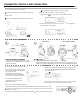
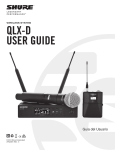
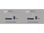
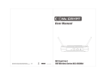
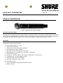
QLXD2 Service Manual
HAND HELD TRANSMITTER
25A1164
PRODUCT DESCRIPTION
Figure 1. QLXD2 Hand Held Transmitter
General Product Description
QLXD Wireless is a digital wireless microphone system. The system comprises a bodypack transmitter (QLXD1), a handheld
microphone transmitter (QLXD2) and a single channel receiver (QLXD4). The system operates in the UHF TV band (470 to
937.5 MHz). QLXD Wireless is intended for use in mid-tier presentation, installed, and performance markets.
FEATURES
Notable QLXD1 design features include:
Fast transmitter power on: <1 sec
Segmented LCD interface
Infrared sync with firmware update capabilities
Thread locking TA4 audio connector
High dynamic range “Gain Ranging” audio input
Highly transparent, “compander-free”, low latency, digital audio
256-bit AES Encryption
Operates on 2 AA size batteries or the SB900 rechargeable Li-ion battery pack.
Long Battery life: >10 h with SB900 at 10mW
Wide tuning range (64 MHz at 500MHz)
Selectable output power: 1mW, 10mW
Removable antenna
Charge contacts allow charging SB900 without removal
Metal construction
The transmitter is built in eight board groups (A-J) which are set in software to behave as a specific band for sale. The
transmitter may be reprogrammed to a different band without retuning on a test fixture.
Group A: 470Group B: 534-
H50,H51,H52,H53
Group C: 572-
,J51
Group D: 606-
,K52
Group E: 632-
L51,L52,L53
Group F: 710-
,P52
Group G: 794-806
Group H: 823Group J: 925-
S50
TRANSMITTER CONTROLS AND CONNECTORS
Quick Start
Step 1: Power and Antenna Connection
Connect an antenna to each of the antenna connectors.
Connect the power supply to the receiver and plug into an AC
power source.
Connect the receiver audio output to a mixer or amplifier.
Step 2: Scanning for the Best Available Frequency
1. Press the menu button on the receiver to access the scan function.
Press and hold the power button to turn on the receiver.
2. Press the enter button to start a frequency scan. The scan icon will flash
while in scan mode. When the scan is complete, the selected group and
channel appears on the display.
IN ST R U ME NT OU T
Step 3: Install Batteries into Transmitter
AA Batteries
Press the side tabs on the bodypack or unscrew
the cover on the handheld as shown to access the
battery compartment.
Shure SB900 Battery
• AA Batteries: Place batteries (note polarity markings) and AA Adaptor as shown
• Shure SB900 Battery: Place battery as shown (note polarity markings), remove AA
Adaptor from bodypack transmitter, stow AA Adaptor in door for handheld transmitter
Step 4: IR Sync to Create an Audio Channel
1. Press the sync button on the receiver.
The red ir LED will blink indicating that
sync mode is active.
3. sync good appears on the display when IR sync is complete. The
blue rf LED will illuminate indicating that the transmitter is within
range of the receiver.
2. Align the IR sync windows of the
transmitter and receiver at a distance
of <15 cm (6 in.). When the transmitter
and receiver are aligned, the red ir
LED remains on and the sync will
automatically occur.
Note: If the IR sync fails, repeat the IR sync procedure, carefully maintaining
alignment between the IR windows of the transmitter and receiver.
Step 5: Sound Check and Gain Adjustment
1. Test the transmitter at performance levels while monitoring the audio meter and the audio LED.
Tip: The audio meter should display at least 3 bars and the audio LED should be green. Reduce the gain if there is
audible distortion of the audio.
2. Increase or decrease the gain if necessary by pressing the
buttons on the receiver front panel.