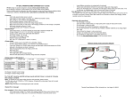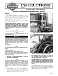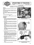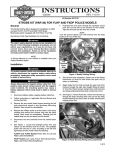
1
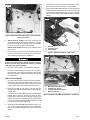
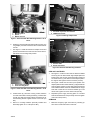
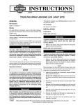
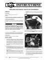
-J02151
REV. 2008-08-26
TOUR-PAK FOR FLHP/E/I, FLHTP/I POLICE MODELS
All Models: Disconnect the emergency light connectors
to allow the power supply mounting plate to be repositioned.
GENERAL
Kit Number
53631-04, 53632-04, 53634-04, 53637-04
is05735
Models
This Police Tour-Pak Kit is designed for installation on 2000
and later FLHP/E/I and FLHTP/I (Police) Model Motorcycles.
2
Additional Parts Required
2009 and later models will require separate purchase and
installation of adapter plate kit 53196-09 to complete installation.
1
The rider's safety depends upon the correct installation
of this kit. Use the appropriate service manual procedures.
If the procedure is not within your capabilities or you do
not have the correct tools, have a Harley-Davidson dealer
perform the installation. Improper installation of this kit
could result in death or serious injury. (00333a)
NOTE
This instruction sheet references service manual information.
A service manual for your model motorcycle is required for this
installation and is available from a Harley-Davidson Dealer.
1. Hex head cap screws
2. Phillips screws with washers
Figure 1. Remove Radio Tray and Hardware - '08 & earlier
shown
is05774
1
Kit Contents
See Figure 16, Figure 17, Table 1 and Table 2.
INSTALLATION
1.
2.
2
2
See Figure 1. Remove the hex head cap screws (five
screws for '08 and earlier and four screws for '09 and later)
and two smaller Phillips screws (with washers) securing
existing radio tray to mounting rail. For '08 and earlier
models leave the two rectangular license plate spacers
and set aside three remaining spacers. Discard screws
and washers, but save nuts for installation later. Discard
radio tray.
1
2009 and later models: See Figure 2. Carefully remove
Tour-Pak assembly and hardware from shipping container.
Open Tour-Pak. Remove the five rubber isolator studs
securing the power supply mounting plate to the bottom
of the Tour-Pak.
2008 and earlier models: Remove five rubber isolator
studs and set aside. You will use these again later. For
'09-later models, these studs will not be used. Rather, use
the five longer rubber isolator studs in the adapter plate
kit.
-J02151
1. Disconnect emergency light connectors
2. Remove power supply plate fasteners
Figure 2. Remove Power Supply Plate Hardware
3.
See Figure 3. Raise and position (lean) the mounting plate
(1) up against the front side of Tour-Pak to provide access
to the Tour-Pak permanent mounting holes. If necessary,
use a cable strap to hold plate in place. Temporarily set
Tour-Pak assembly aside.
Many Harley-Davidson® Parts & Accessories are made of plastics and metals which can be recycled.
Please dispose of materials responsibly.
1 of 7
is05737
1
4.
Install washer to bolt and position bolt above hole at rear
center Tour-Pak above rear block mounting position.
5.
Orient rear mounting block (with hole running vertical) and
position between recessed area of Tour-Pak (near center)
and rail support. Install bolt through Tour-Pak, rear block
and rail, then loosely Install spacer followed by washer
and nut.
is05738a
1
1. Power supply mounting plate
Figure 3. Move Power Mounting Plate to Install Tour-Pak
- '08 & earlier shown
4.
2007 and earlier models: See Figure 4. Remove the
quick release seat pin clip from the seat pin (1) and pivot
the seat forward as far as possible. It may be necessary
to tie or brace seat in the full forward position.
2008 and later models: Remove the pin and pivot bolt in
front of seat.
5.
2
3
1. Seat pin
2. Trim panel nuts
3. Cable straps
Remove the two trim panel nuts (2) and washers securing
the trim panel assembly to the fender and remove panel.
Save hardware and panel for re-installation.
Figure 4. Remove Trim Panel - '08 & earlier
is05739
To prevent accidental vehicle start-up, which could cause
death or serious injury, disconnect negative (-) battery
cable before proceeding. (00048a)
6.
Disconnect battery cables, negative battery cable first.
7.
Cut the two cable straps (3) securing the rear emergency
lamp harness to the support rail. Discard cable straps.
Route rear emergency lamp harness away from Tour-Pak
mounting area.
1
1.
See upper half of Figure 5 and Service Parts Illustration.
Return to the Tour-Pak and install four long 1/4-20 x 2-1/2
inch hex head screws (1) with 1/4 inch washers from inside
bottom of Tour-Pak at four permanent mounting holes.
2.
Raise the Tour-Pak up and position onto rack with four
mounting bolts aligned with four holes in support rail (two
on each side).
See lower half of Figure 5. Make sure the two license plate
bracket spacers remain in position and bolts can pass
through them. Obtain the two rectangular luggage rack
spacers and four nuts saved from previous step. Obtain
four new 1/4 inch washers and loosely install washers and
nuts to secure Tour-Pak to support rail.
3.
3
2
2008 and Earlier Models
4
1.
2.
3.
4.
Mounting bolts and washers
Luggage rack spacer
License plate bracket spacer
Washers and nuts
Figure 5. Install Tour-Pak Mounting Hardware - '08 & earlier
See Figure 6. Obtain Rear Mounting Block (w/1 hole), 1/420 x 2-1/2 hex head bolt and two 1/4 inch flat washers
from kit. Also obtain rectangular spacer, and nut removed
earlier.
-J02151
2 of 7
is05740
is05742
1
1
1
1
2
2
1
3
1. Hex head cap screws and washers
2. TORX head screws
1. Mounting block
2. Spacer
3. Washer and nut
Figure 8. Installing Adapter Plate
Figure 6. Install Tour-Pak Rear Mounting Bracket - '08 &
earlier
6.
Obtain the remaining Mounting Block with two holes, two
long Phillips pan head screws and two #10 flat washers
from kit.
7.
See Figure 7. Install flat washers to Phillips screws and
position screws above two holes near front center of TourPak above front mounting block position.
is05744a
1
1
2
is05741
1. Isolator studs
2. Screw and washer
2
Figure 9. Install Tour-Pak Mounting Hardware
2009 and Later Models
1
1.
See Figure 8. Locate air tank reservoir. Remove TORX®
screws (2) from air tank bracket. Align adapter plate and
install screws into air tank mounting bracket. Install four
hex head screws (1) and washers in the adapter plate to
the support rails. Tighten screws to 22 in-lbs (2.5 Nm).
2.
See Figure 9. Raise the Tour-Pak up and position onto
adapter plate with five rubber isolators (1) aligned with five
holes in support rail (two on each side) and forward center
hole. Rubber isolators need to be installed with the longer
stud down. Install 1/2 inch screw and washer (2) in rear
center hole. Tighten rear screw to 80 in-lbs (9.0 Nm).
Position block (2) ,with holes running vertical, between
Tour-Pak and air tank mounting bracket (1). Install screws
through Tour-Pak and mounting block and thread into air
tank mounting bracket. Tighten screws to 22 in-lbs (2.5
Nm).
3.
Reposition power supply mounting plate on to isolator
studs and install the five nuts previously removed. Tighten
nuts to 80 in-lbs (9.0 Nm).
Return to mounting hardware previously installed and
alternately tighten to 5-7 ft-lbs (6.8-9.5 Nm).
1.
1. Tank mounting bracket
2. Front mounting block
Figure 7. Install Tour-Pak Front Mounting Bracket - '08 &
earlier
8.
9.
-J02151
All Models
Make the emergency light connections by matching up
wire colors of male and female connectors.
3 of 7
is05744b
Refer to service manual and remove ECM and tray for
access to main battery.
7.
See Figure 11. Route control harness (from Tour-Pak)
along left upper frame tube to PNA accessory connector
in space immediately in front of motorcycle battery.
8.
Connect control harness to PNA accessory connector.
4
5
6
2
3
Connect positive (+) battery cable first. If positive (+) cable
should contact ground with negative (-) cable connected,
the resulting sparks can cause a battery explosion, which
could result in death or serious injury. (00068a)
1
1.
2.
3.
4.
5.
6.
7.
6.
9.
Battery bracket
Screw, 3/8-16 x 1 inch
Washer, 3/8 inch
Battery strap
Screw, 3/8-16 x 1-3/4 inch
Washer, 3/8 inch
Lock nut, 3/8-16 (not shown)
Locate the two-pin connector originally routed to rear
emergency lamp and connect to the two-pin connecter
coming from Tour-Pak.
NOTE
Prior to installing positive battery terminal to battery post, locate
insulated end of positive battery cable (directly after main fuse)
and bend a 90 degree radius into the cable as shown. This will
keep the terminal from kinking when installing terminal to battery post.
Figure 10. Install Battery
is05134
2
3
Connect positive (+) battery cable first. If positive (+) cable
should contact ground with negative (-) cable connected,
the resulting sparks can cause a battery explosion, which
could result in death or serious injury. (00068a)
10. See Figure 12. Route the positive battery cable with main
fuse (1) as shown and loosely install positive battery terminal over existing terminal to battery positive post. Tuck
the main fuse along with the rear emergency lamp harness
(2) down into the space between the battery and the left
upper frame tube as shown. Tighten terminal to 30 in-lbs
(3.4 Nm).
1
1. Battery ground stud
2. Accessory connector
3. Battery positive connector
Figure 11. Under Seat Connectors
is05760
1
NOTE
When performing the next few steps, install battery mounting
bracket, battery strap and battery only. Do NOT connect battery
terminals at this time.
2.
See Figure 10. Loosely assemble battery mounting bracket
(1) with screw (2), washers (3) and nut (7).
3.
Orient and position battery behind mounting bracket as
shown. Loosely install battery strap (4) using two screws
(5), four Washers (6) and two nuts (7).
4.
Make sure battery is centered and mounting bracket is
positioned properly. While pushing mounting bracket forward, tighten bracket hardware to 10-12 ft-lbs (13.6- 16.3
Nm). Return to battery strap hardware and tighten to 1012 ft-lbs (13.6-16.3 Nm).
5.
2
1. Positive cable with main fuse
2. Rear emergency lamp harness connector
Figure 12. Connect Tour-Pak Battery Cables to Motorcycle
Battery
Locate red positive and black negative battery cables in
Tour-Pak. Make sure cables are not touching each other
or anything metal in the Tour-Pak.
-J02151
4 of 7
16. Refer to service manual to install seat.
is05761
17. Return to Tour-Pak and locate positive and negative battery cables. Route positive battery terminal to battery and
install terminal to battery post. Tighten terminal to 30 inlbs (3.4 Nm).
18. Route negative battery terminal to negative battery post
and install terminal. Tighten terminal to 30 in-lbs (3.4 Nm).
19. If not using auxiliary battery, remove red connecting cable
from fuse bar. Failure to do so could cause arc from lead.
1
is05769
1. Cable strap
Figure 13. Secure Tour-Pak Harness to Mounting Rail
1
is05762
1
1. Trim panel
Figure 14. Install Trim Panel
11. Route the negative battery cable around the front of the
battery and install terminal over existing terminal to negative battery post. Tighten terminal to 30 in-lbs (3.4 Nm).
1. Warning label
12. See Figure 13. Install cable strap (1) to secure Tour-Pak
Harness to mounting rail.
Figure 15. Check for Warning Label
13. See Figure 14. Re-install trim panel (1) to fender using
nuts and washers previously saved (2007 and earlier).
14. Install trim panel cover to protect battery and wiring (2007
and earlier).
20. See Figure 15. Check for load limit warning label (1) on
underside of Tour-Pak lid. If this is not pre-affixed, install
label as shown in figure 15. Insert figure of label on bottom
of Tour-Pak cover, in the center of the cover and squared
so that it is legible when lid is opened.
15. Install ECM caddy and ECM to underseat location (2008
and later).
21. Close Tour-Pak and test rear emergency lights for proper
operation.
After installing seat, pull upward on seat to be sure it is
locked in position. While riding, a loose seat can shift
causing loss of control, which could result in death or
serious injury. (00070b)
-J02151
5 of 7
SERVICE PARTS
is05765
13
2
3
14
9
1
8
10
5
4
6
7
11
15
12
Figure 16. Service Parts: FLHP/E/I and FLHTP/I Tour-Pak
Table 1. Service Parts: FLHP/E/I and FLHTP/I Police Tour-Pak
Item
Description (Quantity)
Part Number
Item
Description (Quantity)
Part Number
1
Cable strap (2)
10006
9
Support tube mounting block
53906-01
2
Phillips pan head screw (2)
2581
10
Flat washer, 1/4 inch (10)
6235
3
Hex screw, 3/8-16 x 1 inch
2879W
11
Flat washer, 3/8 inch (6)
6416
4
Battery bracket
29523-01
12
Flat washer, #10 (2)
6716
5
Battery strap
29525-01
13
Hex lock nut, 3/8-16 (3)
7601
6
Hex screw, 1/4-20 x 2-1/2 inch (5) 3768
14
Hex lock nut, 1/4-20 (2)
7716
7
Hex screw, 3/8-16 x 1-3/4 inch (2) 4720W
15
Tour-Pak latch key (2)
Not Sold Separately
8
Air tank mounting block
-J02151
53905-01
6 of 7
is05776
2
1
3
4
Figure 17. Service Parts: FLHP/E/I and FLHTP/I Police Tour-Pak Adapter Kit
Table 2. Service Parts Table
Item
Description (Quantity)
Part Number
1
Isolator studs (5)
11856
2
Hex screw, 1/4-20 x 1/2 inch
3728
3
Washer, 1/4 inch
6235
4
Socket head screws, 1/4-24 x 1-3/4 inch (4)
4365
-J02151
7 of 7