1
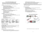
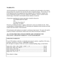
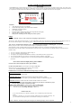
TP-210V LITHIUM POLYMER BALANCER User’s Guide The TP-210V employs advanced balancing technology to actively balance Lithium Polymer batteries, thus making charging much safer. When used in concert with the Thunder Power 1010C charger, a “closed loop” syst em is formed…the safest method available for charging Lithium Polymer batteries. It is important to read this manual and use the balancer correctly. This balancer is intended to be used with 2 to 10 cell packs. MADE IN KOREA FOR THUNDER POWER USA Features: 1 2 3 4 5 6 7 Auto cell detect for any 2 to 10 cell pack Checks and displays battery and individual cell conditions Imbalanced cell voltage warning Over voltage warning Red LED’s light to indicate individual cells being balanced (discharged) Alerts for full, low and over charge status Data port for interfacing with TP-charger and other options Usage To identify “Group A” and “Group B” for charging two packs in series: The group “A” pack (the pack connected to the “A” port of the balancer) M UST be connected to the negative terminal of the charger as shown in the “Y-series connector picture” on the following pages. Failure to make the proper connections here will damage the balancer. After you have read and attached all labels to the Y -series connector and to each battery’s balancing port , you may then connect the first battery “group A” to the Y-series connector terminal “Group A”, repeat step for “Group B”. Next connect the “Group A” battery balancer connector to the balancer (Group A), re peat for the “Group B” battery connector. If the balancer beeps, you have either reversed the balance connectors or the Y -series connection; call Thunder Power at (702) 228 -8883 if a mistake is made. 1. 2. 3. 4. 5. For 2 or 3 cell packs, connect battery to bank 1/Group A For 4 or 5 cell packs, use bank 2/group A For single 6,7 or 8 cell pack with two balancer connectors, connect battery to bank 1/ group A & B For 10 cell pack with two 6-pin connectors, connect both connectors to Bank 2/ group A& B For two 4 cell or two 5 cell packs in series: a Y-series connector must be used, use Bank2 for balancer connectors. Press “Start” button to display battery pack condition: Press the “Start” button to display the battery pack condition: If yellow status LED “flashes”, pack average cell voltage is below 3.6V. Charge the pack to 3.7/Cell or above before checking packs condition You must always avoid deep discharging to this level Conditions below are based on an individual cell voltage being 3.7V or higher A: Imbalance under 0.03V: Yellow status LED “on” steady and red LED’s “on” for 5 seconds. Normal charging, proceed as usual. B: Imbalance 0.03 to 0.2V: Yellow status LED “off” and red LED’s flash for 5 seconds. Charge at 0.3A to balance the pack or proceed carefully with up to 1A maximum charge rate. C: Imbalance over 0.2V: Yellow status LED “off”and red LED’s flash for 60 seconds. Battery may require repair. Keep battery plugged into the balancer until balancing stops. DO NOT charge the battery until balancing stops. If yellow status LED “flashes”, pack average voltage is below 3.6V. Charge the pack to 3.7/Cell or above before checking packs condition You must always avoid deep discharge to this level Additional audio alert: -If any of the individual cells in the battery fall below 3.2V, an audible beep will be emitted for 5 seconds. -If the pack is charged to over 4.3V/cell (overcharged), audible beeps will be emitted continuously. The pack will need to be discharged to below 4.2V/cell before continuing use of the balancer. ** Note: when the “START” button pressed again, the checking display will be repeated. 1 Charging: 1. 2. 3. 4. After checking the battery, connect the battery power lead to the charger, select the charge rate according to battery capacity and condition (see previous steps). Full charge alerts: Double beeps 6 times and repeats 2 times every 30 seconds, “STATUS LED” solid on. Stop charge or wait until charge is completed. Over charge warning (Any cell voltage over 4.3V): Double beep and “STATUS LED” flashing (Please stop charging immediately) Imbalance over 0.2V while charging: Red LED’s are flashing and beeping for 10sec, this will be repeated every minute until conditions change, reduce charge rate to 0.3A and carefully monitor charging conditions. Charging with pulse charger (Astro 109) 1. Charge completion alerts may be activated during phase 3 (double beeps 6 times) 2. Verify the cell count setting, if correct, you may continue charging until finished. Auto self Balancing 1. Plug the battery balancer connector into the correct balancer port. DO NOT simultaneously charge battery. 2. Balancer will bleed/balance if balancing is necessary (red LED’s flashing). If no red LED’s flash, the battery is balanced and ready for charging. Precautions 1. Do not connect BANK1 and BANK 2 connectors at a same time. 2. Do not use in direct sun light, the unit will develop heat when working and direct sun li ght can cause overheating. 3. Do not use when ambient temperature is over 85 degrees F. 4. Use and store in a dry environment. 5. Un-plug the balancer from your battery pack when not in use. It is possible to allow the balancer to work for m any hours at a time but do not “store” the balancer with a battery plugged in. Specifications 0.1% reference voltage controlled by microcomputer chip. Balance cells: 2 to 10 cells in series. Balance start voltage: 4.1V or 3.2V for >0.03V imbalance. Bleeding current: Max 450mA. Imbalance control voltage:+/- 0.005V. 6. Under voltage warning: 3.3V +/- 0.01V. 7. Over voltage warning: 4.3V. 8. Full charge indicator: One or more cells at 4.2V and all others within 0.01V. 9. Size: 4.0” x 1.72” X 0.72” (102mm x 44mm x 20mm). 10. Auto self-balance +/- 0.005V (cell voltage >4.1V/cell). 11. Auto self-balance +/- 0.015V (cell voltage <4.1V/cell). 1. 2. 3. 4. 5. BANK 1 and BANK2 Warning: Never use both bank 1 and Bank 2 simultaneously (Bank 1 & Bank 2 are connected Internally and this could cause a short ). Table-1: Bank #1 Group-A 4 pin header Used with 2s & 3s pack s Used for 6s,7s,8s packs Group-B 6 Pin header Must used in conjunction with (multi-connector pack) Group-A Bank #2 Group-A 6 pin header Used for 2s to 5s pack Used for 9s,10s packs Group-B 6 pin header Only used with Group-A (multi-connector pack) 2 WARNING !!! When charging 2 battery packs in series, you must use a marked Y -series connector. Both power leads and balancer leads must be wired correctly, every connection. If wire connection is incorrect, it will cause damage to the balancer 1) Attach a “group A” sticker to the Black Main Negative lead of your Y-series connector (not the Black Jumper Lead) Attach sticker “group A” to the Black Main Negative side TP6P4E- 6 pin to 4 pin connector, for charging two 3S packs 2) Install stickers provided from your balancer package to battery packs to be used in series. Install “group A” sticker to the balancer connector of one of the batteries Install “group B” sticker to the balancer connector on the second battery WARNING: Make sure proper connection (if connected incorrectly you will damage the balancer) Battery packs intended to charge in series must be connected to the Y-series harness first Connect battery packs “group A” to “group A” of the Y -series connector, connect “group B” of the Y -series connector. Make sure the “group A” balancer connector is connected to “group A” on the balancer Make sure the “group A” balancer connector is connected to “group A” on the balancer 3 (Fig-1) Bank and groups wiring diagram BANK1 1 B5 B5 B4 B3 B4 B4 B3 B3 B2 B2 B1 B1 B2 BANK2 B1 1 BANK1 B6 1 B8 B5 B7 B4 B6 B5 B3 B4 B2 B3 B1 B2 3S +3S B1 4S +4S BANK2 1 Bank1: For use with 2s + 3s (only Group A is used) B10 For use TP 6S,7S,8S packs(used Group A & Group B connector) B9 Bank2: For use with 4s,5s(Only Group A is used) B7 For use TP 10s packs(use both Group A & B connector) For Charging two battery packs in series, you must use a marked Y- series connector(See opposite page//page4) 4s packs built before 2006 require some modification. To modify pack: solder pin 5(yellow) to pin-6(red). B8 B6 5S+5S B5 B4 B3 B2 B1 BANK2 1 Thunder Power USA 4720W University Avenue Las Vegas NV 89103 USA 4