1
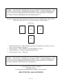
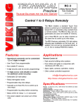
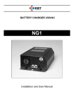
The Coin Operated Pre Pay Telephone
Making It Work – The Way It Was Designed
Building a Coin Controller
----- Preliminary -----
NOT A FINAL VERSION
Colin T Chambers
Page 1 of 38
WARNING – THIS CIRCUIT USES HIGH VOLTAGE TO OPERATE THE COIN RELAY – THIS
VOLTAGE CAN GIVE YOU A SEVERE SHOCK OR KILL YOU – ATTEMPT THIS PROJECT
OLNY IF YOU HAVE WORKED WITH HIGH VOLTAGE AND KNOW HOW TO PREVENT
ELECTRICAL SHOCK! REMEMBER DEATH IS PERMANENT !!!!
DO NOT CONTINUE READING THIS BOOK UNTIL YOU FULLY UNDERSTAND THE WARNING
ABOVE AND ARE WILLING TO TAKEYOUR LIFE IN YOUR HANDS !!!!
Front Cover
1
2
3
4
1. Older Western Electric – With F1 Handset, note absence of pull down coin bucket. No Coin
Box Cover and no Push Coin Return.
2. Western Electric – With G1 Handset, note extra blank for Ace Lock.
3. Automatic Electric – Armored Cord and Push Button Dial.
4. Western Electric (Type) – Single Slot
WARNING – THIS CIRCUIT USES HIGH VOLTAGE TO OPERATE THE COIN RELAY – THIS
VOLTAGE CAN GIVE YOU A SEVERE SHOCK OR KILL YOU – ATTEMPT THIS PROJECT
OLNY IF YOU HAVE WORKED WITH HIGH VOLTAGE AND KNOW HOW TO PREVENT
ELECTRICAL SHOCK! THIS IS THE LAST WARNING !!!
© Copyright 2008 by Colin T. Chambers
All Rights Reserved
Do not reproduce this publication or distribute it in any manner
WEB SITE EDITION – MAY HAVE ERRORS
Page 2 of 38
TABLE OF CONTENTS
There may be errors and the content may be changed, sections added and or edited as this continues to
be revised.
The values of the capacitors that are charged via the opto couplers may need some experimentation,
the timing needed is explained in the text.
It is my guess that most will just read this book, and set it aside. To construct circuits like this requires
a great deal of technical ability. I suggest starting with the simpler one relay controller and using a
Telco type supply and the ringing for the DC, such an old key system power supply.
It would be quite easy to add a 555 timer circuit to control the polarity of a relay feeding the Coin
Relay. This would “time” the call. Longer calls, say over 45 seconds, would collect the coins and
shorter calls would return the coins.
If anyone is really serious about building the circuits described here, please contact me.
This is a WEB SITE Preliminary Edition of a more detailed publication.
Colin T. Chambers
[email protected]
Introduction 5
Coin Telephone Types 7
Coin Relays 8
Simplified Pay Phone Wiring 9
How the Pay Phone Works 10
Simple Talk and Continuity Tester14
The Power Supply 16
The Controller/Simulator – Type 1 20
The Controller/Simulator – Type 2 25
Adding a Tester or Line Simulator to Your Power Supply 28
Coin Relay Detail 29
Pay Phone Diagrams 30
Parts Sources and Links 35
Books to Read 37
Notes 38
Version 1.2R
Page 3 of 38
-----
Preliminary ----- WEB SITE ---- Pre Publication
Page 4 of 38
INTRODUCTION
In all the major metropolitan areas of the United States, back in the days prior to the time most of you
were born……… Coin Telephones were full pre pay.
Perhaps you have a old pay phone because you’re a collector or maybe you bought one on E Bay or…
well they are around. I first started fooling with pay phones back in high school. I figured out how to
make a call without a depositing a dime. I graduated High School in 1960, so that was a long time and
many pay phones ago.
Recently, prices have risen for coin telephones on E Bay. Buy now! Restore it and make it work.
To make your pre pay phone work and collect coins, it MUST have a pre pay Coin Relay. Look at this
link on the Internet: http://atcaonline.com/coinrelay.html. If you buy a phone on E Bay, you are taking
a chance, many have the coin relays removed to make them work and some just say “complete” and
the seller does not know if it has a coin relay or not. When in doubt, don’t buy it.
This publication will explain more about the operation of the pre pay phone and how to build a simple
circuit that will collect the coin after you hang up the phone. It is not 100% like the old way it worked,
just a simple simulation.
For the construction of the Coin Controller/Simulator, the level of difficulty is medium, for those that
have built electronic kits before. If you have not built electronics kits before this is an advanced
project.
There are two types of Controller/Simulator circuits in this document. Type 1 is for full pre pay
operation with a single switch on the Coin Relay. Type 2 is for a dial tone first pay phone or a coin
relay with 2 switches on the Coin Relay and is much simpler to build.
If I were to calculate the number of variations of pay phones it would probably exceed 10,000 (maybe
more!). Parts are somewhat interchangeable. You can take a Western Electric Top and put it on a
Northern Electric phone. You can take a dial from almost any manufacturer and put it on almost any
phone. This book is general and only mentions a few variations. An experienced collector is probably
your best source of information on the exact type of phone you have and if it is “original”.
Several pages in this book have lines to make it print right when doing double sided printing. Use the
lined pages to make your notes.
Page 5 of 38
----- Preliminary ---
WEB SITE
Page 6 of 38
--
Pre Publication
COIN TELEPHONE TYPES
There are two types of older coin telephones, pre-pay and post-pay. With a pre-pay phone (the most
common) you put the coin in first to get dial tone. Post-pay phones have you put the coin in after the
party answers so you can talk. Pre-pay phones are in use today, usually they make a big clunk when
the coin is collected or returned at the end of the call. The coin relay is controlled by 100 to 130 Volts
DC sent from the Central Office.
In a pre-pay phone the determination to return the coin or collect the coin is made in the Central Office
and the polarity of the Coin Relay voltage sent to the phone determines if the coin will be returned or
collected.
A post pay phone looks the same, it has a relay, but the relay operates on the telephone line current that
powers the telephone. The voltage reverses on the telephone line (this does not happen on a modern
telephone line) when the called party answers, shorts the transmitter, then you deposit your money so
you can talk to them. This publication does not discuss this type of telephone.
To add a bit more confusion, private pay phones (not telephone company ones) and some updated pre
pay phones contain computerized electronic circuits. Each type of phone like this operates slightly
different, and some are quite complicated. This publication does not address this type of telephone.
With the circuits here you will have the option of returning the coin or colleting the coin, but the
choice will be the same each time the phone is used, regardless if the call is answered at the other end
or remains un-answered. Also, only the initial deposit, usually a dime, is the only money needed. You
probably have the phone connected to an unrestricted phone line, so a dime can be used for any type of
long distance or international call. This circuit is for use as entertainment only, just having an old
phone that works.
In a full pre-pay phone you had to put in a coin to get a dial tone. With this circuit that feature is
retained in the Type 1 circuit. Usually a switch on the coin relay stops the dial from working until a
coin is deposited, this was not so on the older phones. I suggest you set your phone up to collect all the
coins!
I have included some greatly simplified diagrams.. An explanation follows the drawing and explains
the basic operation.
You should make notes in this book. It is OK to use pencil. There are a few blank pages with lines, use
these to make notes.
Page 7 of 38
COIN RELAYS
There are two types of coin relays, dual coil and single coil. Both work the same. The single coil is
more reliable.
What You Do Not Want To See – No Coin Relay:
A Modern Single Slot – No Coin Relay
A 3 Slot – Bell in place of Coin Relay
What You WANT To See – A Coin Relay: (Single Coil)
Page 8 of 38
SIMPLIFIED PAY PHONE WIRING – FULL PRE PAY – TYPE 1
Page 9 of 38
HOW THE PAY PHONE WORKS
There are three additional parts in a Coin Phone compared to a “Regular” Phone. They are: 1) The
Coin Relay, 2) The Coin Deposit Switch, and 3) The Dial Shorting Contact (located on the Coin Relay
but not present in all phones).
In the 1960’s and before, all Coin Telephone Lines were full pre-pay. You did not get dial tone when
you picked up the handset and listened, all you heard was “line noise”. A coin was deposited, this
closed the Coin Deposit Switch, these phones used a ground start line, completing a path to ground and
the Central Office gave you dial tone. At the same time the pulse contacts on the dial were un-shorted,
with the contacts shorted the dial became unusable, and you could dial your number. This type of
service was called “ground start” and a path to ground forced the central office to return dial tone for
originating a telephone call.
After the 60’s the telephone companies began converting to “Dial Tone First”. When you picked up
the handset you had dial tone, if you tried to dial you could only call toll free numbers, 411, 911 and
the operator. The smarts were in the central office and you had to deposit a coin to dial any other
number, and the Central Office detected the Coin Relay being connect to ground, this was at the same
time that push button (Touch Tone®) dials started to appear. (Use the Type 2 Circuit for this phone)
When you hang up the phone the Central Office sends out “Coin Battery” and polarity of the voltage
determines if the coin will be collected or returned. Coin battery is about 110 Volts DC.
The Coin Relay “operates or closes) the switches on the Coin Relay reset, coins are collected or
returned depending on the polarity of the voltage, the dial is shorted to prevent it from dialing and the
phone waits for the next user.
Basic Operation:
Outbound Call:
Caller picks up telephone handset, hears a bit of line noise but no dial tone.
An initial deposit is made, a switch is tripped, connecting the Coin Relay to ground. This is detected by
the Central Office, dial tone is heard.
This could be 5 cents or 10 cents, depending on the age of the telephone. Later telephones had a
nickel lock up relay that required 2 nickels. Some Coin Relays have 2 sets of contacts, one of
them removed a short across the pulsing contacts of the dial.
The call is dialed.
Caller hangs up and if the call is not completed the deposit is returned, if a complete call the coins are
collected and stored in the phone.
A 110 Volt DC pulse is sent from the Central Office to operate the Coin Relay. Once the relay
operates the switch is restored to the normal position.
Page 10 of 38
Inbound Call:
The phone rings, and is answered, no coins are needed and the Coin Relay is not operated at the end of
the call
Here is the more complicated drawing of a Dial Tone First Phone and I will explain exactly what takes
place. In a Pre Pay Phone the Coin Relay contacts are connected across the Dial Pulse contact only.
There are many variations, three major manufacturers, various upgrades and so on. The explanation
that follows can be used with most of them. I have added a very simple network, a 150 or 200 Ohm 3
Watt resistor and 2 Microfarad capacitor. This can substitute for a network or induction coil, and
provide good talking and listening volume. Many older pay phones used an external network and this
is a way to put it all in the phone. I have shown a ringer and capacitor, often in an external box under
the pay phone.
Page 11 of 38
Starting with L1 on the Phone Line the DC (Direct Current from the Central Office) flows into the
common lead on the Handset, through the Mic (Carbon Transmitter or Microphone), into the
microphone used to pick up the ding and the gong from the coins, and a Nickel Lock Up Relay (not
present in all pay phone), through the Dial Pulse Contact, through the Hook Switch and out L2 of the
Phone Line. Listening audio (AC or Alternating Current) is pick up across the 150 Ohm resistor and
flows into the Earphone.
There are two options for eliminating the dial pulse clicks in the callers ear. Option A uses a set of
normally closed contacts (usually on the Western Electric phones) that close as soon as the rotary dial
leaves the home position, and Option B uses a set of normally open contacts (usually on the Automatic
Electric phones) that short out the earphone as soon as the rotary dial leaves the home position.
I have shown a pair of diodes, 1N4004, connected across the receiver, this will greatly reduce the line
clicks in the earphone as you operate the hook switch. Modern handsets such as those from the
Western 500/2500 telephone set and the AE 80, have this built in and the diodes are not needed.
There are several wirings for the coin microphone and nickel lock up relay (installed when 10 cents
was the initial deposit to stop just one nickel form giving you a dial tone).
I have shown a set of contacts on the Coin Relay, C1 and C2. On the more modern pay phones this set
of contacts opens to allow the dial pulse contacts when a coin is deposited.
If all else fails to work, and/or you cannot find a wiring diagram for your pay phone, this wiring will
work for the telephone portion of the circuit, you will be able to dial out, talk and listen and the coins
will send a signal into the phone line. I have included several Western Electric wiring diagrams to help
you. The Internet links in this document may also provide help.
The telephone collectors that want everything totally authentic, will reject this “when all else fails”
wiring, but it will work and when the phone is closed, only you and I will know.
You can add a network inside if you can find room and the right network.
Page 12 of 38
CLEAN
TEST
RE-WIRE
The first thing to do is to clean your telephone, this includes cleaning the electrical contacts (the metal
switches). Cleaning the switches is easy, cut a strip of index card about 1/8” wide. Put his strip
between the metal contact (every one on the phone) and manually operate the switch so as to hold the
switch so it holds the index cars strip. Pull the card so it “cleans” the switch as you pull it out of the
switch, continue this until you no longer get a dark back mark (the dirt on the contact) on the card.
The second task is to make sure the telephone is wired properly. This could be easy if the wiring in the
telephone has not been changed or difficult if you need a wiring diagram or the telephone does not
contain a network. Check out this link: http://www.atcaonline.com/WE200payphones.html You can
also search the internet for a Diagram, but I was only able to find a few of them. The best source of old
diagrams I have found is http://www.telephonearchive.com and my friend Jim Prather has scanned a
lot of them.
The third task is to re-wire the telephone and bring out the 2 wires to the Coin Relay and 2 wires for
the coin switch. This depends on the Type 1 or Type 2 circuit your going build.
For a Type 1 circuit, you should have 7 wires coming out of your phone, Tip and Ring for the
telephone line, two wires for coin relay, two wires for the coin switch and a heavy wire for a ground
(the metal back of the phone) for safety. A three pair or four pair inside wiring type telephone cable is
ideal. Pair 1, Tip and Ring, Pair 2 Coin Relay and Pair 3 the coin switch.
For a ground wire it is suggest you run a number 16 or heavier gauge wire. Make sure the paint is
removed where this is connected to the backboard of the phone AND that you run a wire from the
upper housing to the back housing of the same gage of wire. You may want to strip out a 3 conductor
line cord and use that wire, it is quite flexible.
For cleaning your phone use a combination of Windex and rubbing alcohol 50/50, just make sure it
does not dissolve the paint. For the handset use Novus Plastic Polish (www.novuspolish.com).
.
The next page contains a handy-dandy-simple tester. You can use this to test the telephone circuit and
to check for any broken wires.
You should use a drawing that is for the pay phone you have and check all connections with the tester.
It is ok to put paper tags on wires to keep track of things, don’t use masking tape, it leaves sticky stuff.
I have included a composite drawing of a Western Electric Pay Phone of the Dial Tone First design
showing the connection of a 425 Network.
Page 13 of 38
SIMPLE TALK AND CONTINUITY TESTER
Parts List
9 Volt Alkaline Battery and matching Battery Clip
LED – Almost any type of LED will work
Resistor – 330 Ohm ½ or ¼ watt (Orange, Orange, Brown, Gold)
Clip Leads – Buy a package of 10 (you will use them later)
This should be built now, it will help you test the talk circuit in the pay phone and verify all
connections. The tester provides about 20 milliamps or so of current, this will make a talk circuit, but
may not operate the nickel lock up relay (on 10 cent coin mechanisms) unless you lock it in with your
finger.
The resistor and LED can be taped to the battery with electrical tape. For clips get a package of clip
leads, the cheap ones about 10 for $3 and use the clips.
Test The Following
The talk circuit of the telephone.
(If you do not have an external network connected you may want to use the resistor/capacitor
substitute network for testing) Can you talk and hear? If your drip the coin deposit switch can
you dial (the LED will flash with dial pulses). Does the hook switch disconnect the telephone
and the LED go out? Is there any noise in the phone? (You may need to clean the contacts on
the hook switch and dial.) Are the annoying clicks in the receiver? (Possible incorrect wiring.)
Page 14 of 38
The Coin Relay
After completing the wiring and running out the separate wires for the Coin Relay, you should
show a connection on the wires for the Coin Relay, but NO CONNECTION to any other part of
the phone or any other wires.
The Colin Switch
After completing the wiring and running out the separate wires for the Coin Switch, you should
show a connection on the wires for the Coin Switch, when you deposit a coin and trip the
switch, but NO CONNECTION to any other part of the phone or any other wires. The
connection should disappear when you restore the switch to the normal position.
Feel free to test other parts of the telephone and learn to use your tester. If you have other antique
telephones use it as a talk tester. DO NOT TEST ANYTHING THAT HAS ANY POWER SOURCE
OR BATTERIES CONNECTED TO IT.
Page 15 of 38
THE POWER SUPPLY
Second to be constructed will be the power supply. In building mine, I obtained my parts from either
All Electronics (www.allelectronics.com) or Marlin P. Jones (www.mpja.com). Other sources are
Mouser (www.mouser.com) or Jameco (www.jameco.com). The first two are surplus houses and may
not always have everything in stock. I estimate the cost of the power supply at about $50 or so.
The power supply may also be used to test standard telephones with the addition of two relays, this is
covered at the end of this document and the high voltage may be used to test coin relays (provided you
do it without electrocuting yourself!). It is imperative that you use a grounded power outlet, a grounded
power cord and connect this ground to the metal of the coin telephone for safety. A separate, more or
less permanent, ground wire from the frame of the coin telephone to a known good ground is a an
alternative.
A standard transformer is used, but is connected slightly different from the original wiring. The
transformer is rated 120/240 Volts AC with two primary windings. The windings are normally
connected in parallel for 120 VAC and in series for 240 VAC. Only one of those windings will be
connected to 120 VAC, this reduces the output power of the transformer, but it is way over rated for
this application and there is still plenty of power available. The second primary winding will be used to
furnish the high voltage. This provides an isolated power source, not connected to the power line and a
bit safer.
The transformer is MPJA Part Number 7843-TR. It is rated at 18 Volts AC and 2 amps. When changed
to DC it will be about 24 Volts DC and about 300 milliamps (0.3 Amps) will be available. The 120
Volts AC will be change to about 160 Volts DC but is current limited by a 4 watt 120 Volt night light
to about 35 milliamps (0.035 Amp). The lamp also acts as an indicator of a short circuit.
You MUST use a 3 wire cord, with a ground pin, and connect it to a known good GROUNDED outlet
for complete safety and this ground must be connected to the metal case of the pay phone. As an
alternative you may run a ground wire from the metal case of the pay phone to a known good ground,
such as a ground rod pounded into the earth.
WARNING – THIS CIRCUIT USES HIGH VOLTAGE TO OPERATE THE COIN RELAY – THIS
VOLTAGE CAN GIVE YOU A SEVERE SHOCK OR KILL YOU – ATTEMPT THIS PROJECT
OLNY IF YOU HAVE WORKED WITH HIGH VOLTAGE AND KNOW HOW TO PREVENT
ELECTRICAL SHOCK! THIS IS THE LAST WARNING !!!
You can use a standard telephone company 24 VDC Power Supply with 30 Hz Ring Generator. Use
the Talk Battery connection for the Simulator/Controller and the 30 Hz supply as the source for the
High Voltage DC. Connect the 30 Hz to the input of D2. The voltage will be a bit lower compared to
the design shown on the next page, but will work just fine.
Page 16 of 38
Page 17 of 38
Power Supply – The Parts
Parts List
TR - Transformer – Dual Primary 120/120 Volts, Secondary 18 Volts 2 Amp
Fuse – 1 Amp AGC or 3AG and fuse holder – Protection
D1 D2 – Bridge Rectifier 400 PRV 1 or 4 Amp – AC to DC
R1 – Resistor 2.7 K Ohms ½ Watt – Current Limiter
R2 – Lamp 120 V 4 Watt Night Light – “Fuse” Short Circuit Indicator
R3 – Resistor 220 K ½ Watt – Discharges Capacitor
C1 – Capacitor 2200 Mfd 35 Volts DC – Filter
C2 – Capacitor 100 Mfd 200 Volts DC – Filter
LED – Any common LED – On Indicator
SW – Switch SPST
3 Wire GROUNDED Line Cord
Parts List – With Detailed Explanations
Case and …
Get a case that is easy to work in, small is nice but not easy to work with. A Euro Style
terminal strip is good to use, screws are surrounded by plastic (semi insulated).
TR - Transformer – Dual Primary 120/120 Volts AC, Secondary 18 Volts AC 2 Amp
The two primaries let you use this on a standard USA power line, 120 Volts AC, or in
Industrial applications or Internationally, 240 AC Volts. Here in the USA the windings are put
in parallel and then there is full output. Using just one winding on 120 Volts cuts the available
power down to slightly under half. By doing this the second “primary winding” is used as a
“second secondary winding” to provide about 120 Volts AC. You line voltage will vary from
115 Volts to 118 Volts in most cases. This provides for an isolated (non grounded) source of
voltage for the Coin Relay after it is rectified to DC.
Fuse – 1 Amp AGC or 3AG and fuse holder – Protection
This fuse will “blow” or open up if you short the 24 Volts DC, the High Voltage is protected by
the 120 Volt lamp and shorting that will not draw too much current.
D1 D2 – Bridge Rectifier 400 PRV 1 or 4 Amp – AC to DC
This changes the AC into DC. The current is small and you can either use a bridge rectifier
rates at anything between 1 and 4 amps. Or, you can just use four 1N4004 diodes and put them
in a bridge configuration.
R1 – Resistor 2.7 K Ohms ½ Watt – Current Limiter
Limits the current to the LED.
R2 – Lamp 120 V 4 Watt Night Light – “Fuse” Short Circuit Indicator
Page 18 of 38
Limits the current available for operating the Coin Relay. The 160 Volts is a bit high (you get
1.41 times the AC Voltage when you change it to DC). This lamp limits the current, prevents
large sparks and does not overload a Coin Relay. If you do short the output the lamp will light.
You may wish to mount the lamp so the filament can be seen by a small hole in the case. Do
this only if you plan to use the power supply for general testing as the lamp will not normally
light.
R3 – Resistor 220 K ½ Watt – Discharges Capacitor
A safety resistor to discharge the high voltage capacitor when the power supply is unplugged.
C1 – Capacitor 2200 Mfd 35 Volts DC – Filter
Filters the 24 Volts DC, a large capacitor is used so that you can also use the power supply as a
telephone line simulator.
C2 – Capacitor 100 Mfd 200 Volts DC – Filter
Only a small capacitor is used. This is used to charge another capacitor in the controller. This
also prevents large sparks if you short the output.
LED – Any common LED – On Indicator
The “ON” light. Any LED will work, a high output one is suggested.
SW – Switch SPST
Simple ON/OFF switch.
3 Wire GROUNDED Line Cord
To save money, get an old PC line cord and cut off the end that goes to the PC.
Page 19 of 38
THE CONTROLLER/SIMULATOR – TYPE 1
With this circuit coins are either collected OR returned. There is no attempt to determine if a call is
complete to collect the coins or incomplete to return the coins.
Steps of Operation
Outbound Call:
Deposit a coin(s). The switch on the coin relay is activated and Relay CD (Coin Detect) operates. The
Tip/Ring circuit is complete (CD1) and you get dial tone.
Line current flows, the Off Hook Detector causes Relay LL (Line Lock Up) to operate and stay
operated.. This is a slow release relay and will only release after you hang up for greater than 200
milliseconds, this is controlled by C3.
You place your call and call anyplace and talk any amount of time. When you hang up Relay LL
releases after about 200 milliseconds. Actually the time needs to be set so that the relay will not open if
you dial a Zero, but if you dialed “12” it would. You could test this by using your finger to slow down
the dial, and then the relay should open.
When LL releases a charged C4 operates Relay PY (Pay) for about a second, this charges C6 and then
C6 dumps into the coin relay causing it to operate. The Coin Relay is restored to normal operation and
Relay CD now opens.
This is the simplified explanation.
Inbound Call:
Ringing appears on the phone line, the Ringing Detector operates Relay RU (Ring Up) and C2 holds
the relay operated for a bout 8 seconds, or 1 and one-half complete ring cycles. A contact RU1 lets you
get dial one without a coin deposit.
You answer the phone and the Off Hook Detector operates Relay LL. Contact LL1 on this relay lets
you remain connected.
When you hang up Relay LL releases and only coin deposit will let you talk again.
Other resistors in the circuit short out some of the capacitors to discharge them and reset them.
If you use a Telephone Company Power Supply for this circuit use the Talk Battery connection.
Page 20 of 38
Page 21 of 38
Type 1 Simulator – The Parts
Case and …
You will need some sort of case, size depends on the relays you pick and how small an area
you want to work in. I suggest you use a terminal strip, Euro Style, for all connections.
Relays
All Relays are 24 Volts DC DPDT (Double Pole Double Throw) and can be small or large or
even 4PDT, just depends on what you find cheap. I find 4PDT ones in surplus are the cheapest,
and just glue them to the case, nice clicks that way, then you can follow the sequence of
operation. If you pay over $5 each you paid too much.
Q1 Q2 – Transistors 2N4401
This is a higher voltage and higher current one. Usually about 5 for $1
OC1 OC2 – Opto Coupler
Single LED to a transistor junction. Lighting the LED makes the transistor conduct. Type
4N25, but it is rated at only 30 VDC, so the voltage is reduced to about 20 volts by a resistor
combination. Surplus cost under $1 each.
C1 – 0.1 Mfd 250 Volts Non Polarized
Isolates the DC of the phone line from the AC, the ringing.
C2 – 47 Mfd 35 Volts
Timing capacitor. Charges when OC1 conducts. Value dependent on several factors. It should
keep Relay RU operated for about 8 seconds or about one and half ringing cycles.
C3 – 2.2 Mfd 35 Volts
Timing capacitor. Charges when OC2 conducts. Value dependent on several factors. It should
keep Relay LL operated for about 200 millisecond after the phone is hung up and must keep
Relay LL operated when Zero is dialed.
C4 – 220 Mfd 35 Volts
Timing capacitor. Dumped into Relay PY and C5 to keep Relay PY operated for a second or so
to ensure C6 is dumped to the Coin Relay to keep it operated.
C5 – 220 Mfd 35 Volts
Timing capacitor. Keeps Relay PY operated for a short time.
C6 – 220 Mfd 200 Volts
Provides power to operate the Coin Relay. Charges to 160 VDC, but does not overload Coin
Relay because voltage falls as soon as it is connect to the Coin Relay.
R1 – 10K
Limits ringing current into OC1 and provides a good match to the ringing phone line.
R2 – 470 Ohms
Reduces spikes on the phone line so they are not applied to OC1.
Page 22 of 38
R3 – 22K
Limits current to OC1 and with R4 forms a voltage divider to reduce the voltage to OC1.
R4 – 100K
Part of voltage divider for OC1.
R5 – 6.8K
When OC1 conducts about 5 volts appears across this resistor to operate Q1.
R6 – 2.7K
Limits current to the base of Q1..
R7 – 22K
Limits current to OC2 and with R5 forms a voltage divider to reduce the voltage to OC2.
R8 – 100K
Part of voltage divider for OC2.
R9 – 6.8K
When OC2 conducts about 5 volts appears across this resistor to operate Q2.
R10 – 2.7K
Limits current to the base of Q2.
R11 – 470 Ohm
Discharges C4 to reset timing when line is on hook.
R12 – 100 Ohm
Limits current to charge C4.
R13 – 100 Ohm
Limits current to charge C5.
R14 – 220 Ohm
Limits current discharged into Coin Relay and limits charge current to C6. Best to use 2 each
470 ohm ½ watt resistors in parallel for about 235 ohms at 1 watt for this resistor.
R15 – 220K
Discharges C6 to remove any charge after Coin Relay is operated.
D1 – 1N4004
Allows C2 to charge and not discharge thru R5.
D2 – 1N4004
Spike protection for Q1
D3 – 1N4004
Allows C3 to charge and not discharge thru R9.
Page 23 of 38
D4 – 1N4004
Spike protection for Q2
D5 – 1N4004
Spike protection.
BR1 – BR2 – Bridge Rectifier
1 Amp bridge or 4 each 1N4004 diodes
All resistors ½ watt, unless noted.
Relay Functions
CD – Coin Drop Detect
When the switch on the Coin Relay Closes, this relay operates.
LL – Line Lock Up
A slow release relay, timing by C3. Relay should stay operated during dial pulsing.
PY - Pay
RU – Ring Up
Operates when there is ringing on the phone line and stays operated for 8 seconds.
Relay Contacts
CD1
Closes and allows phone to get dial tone.
CD2
Completes circuit to Relay PY.
LL1
Maintains connect on phone line to pay phone.
LL2
Charges and discharges C4.
PY
Charges C6 then dumps it to Coin Relay.
Page 24 of 38
THE CONTROLLER/SIMULATOR – TYPE 2
This is for a dial tone first phone, or one that has two sets of contact on the Coin Relay, one set for the
“ground” connection and one set for shorting the dial and the nickel lock up relay.
The advantage of this circuit, if you have several Pay Phones and they are ALL of this type, is that you
only need one circuit for all the phones. If you only use one phone at a time, each phone will work and
only the phone you are using will thump when it comes time to collect the coins.
Page 25 of 38
Parts List
C1 – 2.2 Mfd 35 Volts
Timing capacitor. Charges when OC2 conducts. Value dependent on several factors. It should
keep Relay LL operated for about 200 millisecond after the phone is hung up and must keep
Relay LL operated when Zero is dialed.
C2 – 220 Mfd 200 Volts
Provides power to operate the Coin Relay. Charges to 160 VDC, but does not overload Coin
Relay because voltage falls as soon as it is connect to the Coin Relay.
R1 – 470 Ohms
Reduces spikes on the phone line so they are not applied to OC1.
R3 – 22K
Limits current to OC and with R3 forms a voltage divider to reduce the voltage to OC1.
R3 – 100K
Part of voltage divider for OC1.
R4 – 2.7K
Limits current to the base of Q1.
R5 – 6.8K
When OC1 conducts about 5 volts appears across this resistor to operate Q1.
R6 – 220 Ohm
Limits current discharged into Coin Relay and limits charge current to C6. Best to use 2 each
470 ohm ½ watt resistors in parallel for about 235 ohms at 1 watt for this resistor.
R7 – 220K
Discharges C6 to remove any charge after Coin Relay is operated.
D1 – 1N4004
Spike protection for Q1
LL – Line Lock Up – Relay 24 VDC DPDT
A slow release relay, timing by C1. Relay should stay operated during dial pulsing.
Q1 – Transistor 2N4401
This is a higher voltage and higher current one. Usually about 5 for $1
OC – Opto Coupler
Single LED to a transistor junction. Lighting the LED makes the transistor conduct. Type
4N25, but it is rated at only 30 VDC, so the voltage is reduced to about 20 volts by a resistor
combination. Surplus cost under $1 each.
Page 26 of 38
D1 – Diode 1N4004
Spike protection for Q2
BR1 – Bridge Rectifier
1 Amp bridge or 4 each 1N4004 diodes
See Type 2 Controller/Simulator for additional information.
This uses the same power supply. While you could use a wall wart for the 24 VDC, the High Voltage
is still needed for the Coin Relay.
Page 27 of 38
ADDING A TESTER OR LINE SIMULATOR TO YOUR POWER SUPPLY
There is excess power on the controller/simulator and you can make use of it. Build this circuit and
you have a tester for all your other old telephones. The jack is for the new phone (2500) and clips leads
or a jack may be used for the old phone. It is just a simple talk circuit.
Relay (RLY) contacts are not shown as they are not used. Relays are 24 Volts DC, 4PDT, 650 or 700
Ohms.
You can leave telephones connected to this and off hook, as long as you like. When a telephone is off
hook, the relay associated with that telephone will operate, if you dial with a rotary dial the relay will
click as you dial. It may be necessary to slightly bend some of the relay contacts or adjust the relay
spring to make it operate and release as you dial the phone and as you go on hook and off hook.
Each time you go off hook on the old telephone the LED will light, it will blink when you dial.
With a telephone connected, wiggle all the wires and listen for noise, if you find a loose connection
tighten the screw. If you find a bad wire, replace it. If you find a dirty contact clean it.
Don’t worry about adding a long line cord or two or three, the tester will still be functional with
hundreds of feet of line cord. You can also put this in a second case and run a power wire to the DC
supply you just built.
Leaving the 2500 telephone set off the hook when testing the old telephone will have no effect. It may
be possible to use a speaker phone type of set for the 2500 telephone set allowing you hands free
testing. Some types of speakerphones may not work this way, but perhaps you can find one that will.
This makes an easy way to listen for noise by wiggling things and listening for noise or noise when
you operate the hook switch (should just be a single click), put the speaker phone on mute and turn up
the volume so you can hear all the noise. Some older 2500 telephone sets did not have a polarity guard,
if the tone dial does not work, reverse the leads on the mod jack.
Page 28 of 38
COIN RELAY DETAIL
There are a number of variations in Pre Pay Coin Relays. Modifications are shown, depending on the
type of relay.
The last two should be modified as to the type of circuit you will use, running out the coil wires
separately for the Type1 Circuit.
Coin Relays start to operate at about 40 VDC, but operation is not reliable. At least 70 Volts is needed
for a well adjusted Coin Relay.
Page 29 of 38
PAY PHONE DIAGRAMS
The next page shows the most common type of Pay Phone(s) wired for Dial Tone First. These were
used just before the replacement of 3 Slots by Single Slot Pay Phones.
I do not know the source of this drawing, but it looks very much like an official diagram. The
connections to a 425 network are shown. In this drawing it is shown as wired externally. Pay Phones
after this date have internal networks and bells inside.
The 685 Subscriber Set, is a box that contains a network and a bell. The application for this was for
pay phones and 212 Type Phones (a wall mounted set with a dial and a handset).
If you decide to “convert” you pay phone you can put a network in the phone, if you can find room, or
in the coin box and then use a small plastic cup for the coins.
Due to the many types of Pay Phones, you may not be able to find the exact wiring diagram.
Bell System Practices (BSPs) were published at AT&T for every model but are very difficult to find. A
book was published called the “Coin Service Manual” but usually goes for a very high price. It was a
compilation of BSPs and there are several editions.
I suggest you make a copy of one of the diagrams and then trace all the wiring in your phone. Use the
small paper tags with the string to label items, using masking tape leaves sticky stuff. If you are not
experienced at reading diagrams, have a friend who understand them.
Diagrams
“Official Western Electric Diagram” Modern Dial Tone First – Re-drawn
Older Double Coil – Re-Drawn
Connections for 101A or B Coil
Page 30 of 38
Page 31 of 38
Page 32 of 38
Page 33 of 38
This is a copy from a BSP showing the connections for an older Pay Phone using a 101 Induction Coil.
There are several variations and a 101B Coil has an “M” terminal that the Coin Relay may be connect
to.
Three are probably several hundred other diagrams. I have only presented a few.
Page 34 of 38
PARTS SOURCES AND LINKS
This is only a partial list, check each site for other links
The Bell System Memorial a very comprehensive web site and I suggest you order the CDs:
http://www.bellsystemmemorial.com
Telephone Collectors Sites: (Join them)
http://atcaonline.com
http://www.telephonecollectors.org
http://www.telephonearchive.com
Old Telephones Part Source:
http://www.phonecoinc.com
Another Telephone Parts Source is:
http://www.oldphoneman.com
Converting your rotary dial phone to a Tone Dial with memory: (and Pay Phone parts)
http://www.oldphoneworks.com
Look for the “rotatone”
Doing your own telephone station wiring:
http://www3.sympatico.ca/bparker/index1.html
http://www.ling.upenn.edu/~kurisuto/phone_wiring.html
Telephone Schematics and Diagrams:
http://www.geocities.com/CapeCanaveral/Campus/1491/
http://www.telephonecollectors.org/library/index.htm
http://www.atcaonline.com
Information from Canada (US & Canadian Phones):
http://www.islandregister.com/phones/phonelink.html
Text on Repair of Old Telephones:
http://www.ccamblab.com/old_tel/rpr_ot21.pdf
http://www.navysalvage.com
Helpful hints on telephone repair, they will also do it for you. Look at the links.
General Tools and Modern Telephone Supplies:
http://www.sandman.com
Great on-line catalog.
http://www.greenlee.textron.com
Greenlee is a source for cable/tone testers
http://www.vikingelectronics.com
Business accessories and special telephones. 48 VDC, 20 Hz, Power supply.
Page 35 of 38
Electronic Parts:
http://www.allelectronics.com
General electronic supplies, test leads, capacitors, relays, etc.
http://www.mpja.com (Recently added a cable tester/probe kit)
MPJA for general electronic supplies, test leads, capacitors, relays, etc.
Another page with hard to find information and links:
http://www.telephonetribute.com
I like the page http://www.telephonetribute.com/signal_and_circuit_conditions.htm
which has all the sounds, like old dial tone.
Old Catalogs and BSP’s (BSP is Bell System Practice)
http://www.telephonearchive.com
Many scanned documents and catalogs. Also a page of internet links. Most complete
collection of Pay Phone diagrams, courtesy of Jim Prather.
Telecom General Information:
http://www.epanorama.net/links/telephone.html
Most of these sites have links to other sites, make use of the links. Links change and go away, search
on Google.
Page 36 of 38
BOOKS TO READ
Principles of Electricity
Published by American Telephone and Telegraph. The last one issued in 1961. Older editions are more
interesting. Often available on EBay for a nominal amount. The 1938 edition and the 1961 edition
would make a good contrast. Excellent book on basic Telephony, but no information on switching or
networks. Definitely worth reading again and again. This is a must have for future engineers!
Old telephone company employees refer to this as The Green Brain. On eBay for $12 or so. A CD of
the 1953 edition is also available.
Old Time Telephones
This is the second edition of this book
By Ralph Meyer, excellent book with lots of theory and wiring diagrams. Well worth the money. Go
to www.schifferbooks.com and search by telephone, they have several books.
Coin Telephones are not covered in these books, they are listed for general information.
Page 37 of 38
Notes
THIS IS A PRELIMINARY DESIGN. The first step as a Design Engineer is to draw up something
that you think will work, then you refine it, do some calculations and re-draw it. Depending on how
good you are, it may or may not work. Next you build one and test your design, do some revisions and
hopefully end up with a good solid designed/product.
This is not a final design, it needs review and detailed examination. Your help is needed. Write me!
The timing capacitors on the transistors need some tweaking.
At this point this is a document that is a little incomplete and the contributions of others will help bring
it to completion.
My background is electronic design, and telecommunications network design. Much of this was quite
technical and provided me with a rewarding career. I was wiring telephones at age 12, doing Central
Office traffic studies at age 15 and designing Telecommunications Networks that required a full
understanding of SS7 at age 50. I like to tell people I know it all, both some truth and some fiction in
that statement. Somehow my interests, hobbies, profession and career all merged into one.
With the aid or a friend in 1970, who lived about 2 miles away from me in Los Angeles, we completed
a call from my house to his house to New York City to Anchorage, Alaska, back to my house to a pay
phone I still have. It was a “collect to coin call”. I quickly deposited coins to accept the call, I talked to
myself as the echo and delay were unbelievable.
I soon learned that I could make money working in Telecommunications and my hobby became my
profession. I changed from Hacker to Design Engineer, it was fun to answer all those questions like,
“Where did you learn all this?” I have never worked for a Telephone Company or Long Distance
Carrier.
Colin T. Chambers
[email protected]
Hutong 胡同 in China 2006 (Note dumb look)
Page 38 of 38