1
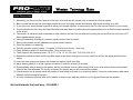
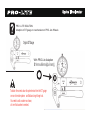
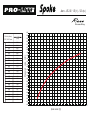
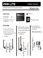
10
Wheelset Technology Guide
Congratulations, you have just purchased the best hand built wheels in the universe. Pro-Lite wheels represent more than 50 years of
continuous experience by the founders of Pro-Lite. Our research and development department has over a hundred years of
engineering experience, ranging from fighter aircraft to building the largest heat treatment oven in the world. You can be sure that unlike
other wheels, when you buy Pro-Lite you are buying not just quality, but years of experience both on and off the bike coupled with a
dedication to quality that is un-rivalled in the bicycle industry today.
The materials that go into to producing your wheels are very carefully selected from suppliers of materials to the military, aerospace and
space industries. It’s our job to make sure you get the best product money can buy. At our factory, each wheel is assembled by hand
and we have no machines at all. Certain brands claim they are selling you hand built wheels, but actually they were assembled in a
machine and then trued by hand because the machine cannot produce a high level wheel good enough to race on.
During the manufacture of your wheels, the spoke tension on every spoke is checked six times before de-stressing, using DT Swiss
spoke gauges. These are not cheap items and ours are lucky to last two months before we replace them. Every week they are
re-calibrated for precision. Each wheel is inspected by no less than three people before the pass certificate is issued. Our team of eight
quality control managers are trained to do the things the hard way; there is no short cut to perfection.
Please inspect and save all packing materials that came with your wheels. If there is any damage to the packaging or to the wheels it is
important to advise your dealer now. Also make sure you register the warranty.
Your Pro-Lite wheels are engineered, designed, and manufactured to aerospace specifications and tolerances, and therefore require
some special attention and care. Basically we advise you not to try to adjust or replace any parts on the wheels, that’s why we have set
up service centres and have trained mechanics who are authorised to service Pro-Lite wheels. Ask yourself this question; would you let
a local guy in his garage to pull out your kids teeth? Or would you pay a dentist to do it? You have invested your hard earned money in a
set of Pro-Lite wheels, they will serve you well for many years to come as long as you have them serviced and repaired through the
correct channels.
We build wheels the hard way – BY HAND ! Wheelset Technology Guide
QUICK RELEASE TENSION
Your hubs are set to specific tensions in the front and rear. This ensures the rolling resistance is far lower than other wheels. When you
tighten the quick release you exert a huge pressure onto the bearings if over tightened. As a rule of thumb we suggest you tighten the
quick release so that it leaves small mark on your hand when tightening it.
The bearings are easily capable of handling the pressure you exert on them but we do know that you will slightly pre-load the bearings if
you over tighten the quick release. You are also erasing the extra benefits you gain with the use of the EZO bearings inside the hubs.
Over tightening a quick release can also strip the threads rendering it useless and could also be dangerous if the threads strip whilst
riding.
BRAKE PADS for Carbon rims
Your carbon Pro-Lite clincher rims are moulded with our Basalt patented braking surface. (http://en.wikipedia.org/wiki/Basalt_fiber)
This means you have the only safe carbon clinchers in the world that you can inflate tyres to 10 bars/ 150 psi and still be safe. When the
brakes are applied the pads generate a huge amount of heat and this can vary a lot depending on the composition of the material used.
In 2006 we tested every available brake pad we could get our hands on. We then rode down an 8km hill in Taichung with the brakes on
at speeds up to 85kmh. Each set of pads was ridden three times. The results were simply amazing. We destroyed over 60 rims in 3
days testing other supplier’s pads. So we are confident when we say don’t use other pads, use genuine Pro-Lite pads, we know why we
are telling you this.
We build wheels the hard way – BY HAND ! Wheelset Technology Guide
On tubular rims also use our specific pad produced specifically for this rim, don’t let people tell you they use other pads without
problems, carbon rims might look the same but they are often very different and saving some small money on pads could wreck your
rims.
We do NOT recommend Campagnolo brake pads.
These have a very low melting point, and might melt excessively under heavy braking, leaving a residue on the rim which is very difficult
to clean. For optimal performance, Pro-Lite carbon brake pads provide the ideal balance of feel and stopping power, these will keep
rims cool under braking.
Pro-Lite brake pads are the only pads specific to all our rims; we cannot be responsible for the effects of non Pro-Lite pads used on our
rims.
NOTE: For cyclocross applications and cantilever brakes, we recommend using Kool-Stop black pads on our alloy – carbon rims. For up
to date advice we do recommend contacting Martin Eadon at X-Gear in the UK for the latest developments on pads.
BRAKE PADS for CLINCHER WHEELSETS
We recommend using Pro-Lite Carbon/alloy rim brake pads with any of our aluminium braking surface, right down to the Como clincher
wheels. Other brand standard brake pads will work, but they do cause premature wear to the braking surface due to the use of
abrasives such as aluminium oxide in the pads. As discussed with our tubular rims, we do not recommend using Campagnolo pads.
Good options include Kool-Stop black.
We build wheels the hard way – BY HAND ! Wheelset Technology Guide
CARE AND CLEANING
Be very careful in what you put on your rims, it is so easy to use the wrong cleaner and damage the epoxy resin and decals also. We
cannot be responsible for damage to your rims by using the wrong type of cleaner. Soapy water is normally all you need; anything
solvent based will damage the rim. There are cleaners on the market around the world that specifically say they will not damage the
epoxy resin but always recommend you contact them to check they will work on carbon rims.
Removal of glue from your rim on tubular rims is something you must do very carefully. It is not something you need to do on a regular
basis as the build up of glue will help ensure when riding in very hot conditions you have all the grip you could need. It also helps when
changing a puncture to get you home if you have forgotten your rim tape with the spare tyre.
HUBS
Pro-Lite hubs are machined to amazingly high standards. We are in an amazing position compared to other manufacturers; we never
get warranty issues with them. Why? You might ask. Well the answer is simple. Every hub on assembly if torque to a special tension
unique to each of the hubs we use. This means that while we are building them into wheels we apply a great deal of pressure to the
flange. This effectively stretches the hub and reduces the friction on the bearing surface. It is critical that the tension used to pre-tension
the wheel is applied exactly, so that after building the reduced friction is correct, but also there is no excess play in the hub and bearing
surfaces. If you decide to strip down your hubs, ensure that a qualified mechanic re-sets them exactly as before.
We recommend cleaning the hubs with hot soapy water and not trying to use spray type solvent based cleaners as all these do is break
down the grease and damage the seals. There are many types of cleaning brushes on the market and a little bit of imagination will let
you choose the right one for the job. Remember you are looking to clean around the nipples which should be periodically oiled, the
flange area again which needs to be periodically oiled and the freehub body. Don’t forget to clean the quick release and re-oil it as well
as the inside of the hollow axle.
We build wheels the hard way – BY HAND ! Wheelset Technology Guide
Occasionally you might remove the cassette body from the hub and clean out the drive mechanism. It is not necessary to remove the
cassette for this operation, but you can if you wish. This mechanism is incredibly robust and well sealed, but removing dirt that builds up
is often helpful.
To disassemble the front or rear hub, please follow the separate instructions available from the Pro-Lite website.
Complete instructions for hub maintenance are posted on our website, www.Pro-Lite.com
Why do my hubs have play in them?
You might notice that your Pro-Lite hubs feel as though there is some “play” in them while the bike has no rider on it. This can often be
felt by holding the front wheel in one hand and the handlebars in another and rocking toward each other to see if there is any play at the
hubs. This will disappear when the rider is on board the bike. If the rider says you can hear the rim rub the brake blocks when climbing
out of the saddle, then the bearings need to be re-set. Our experience shows that this is due to someone not re-setting the cones on the
hubs correctly after taking them apart. Remember if it is not broken don’t try to fix it!!.
Rocking feeling on Bolzano hubs
Although this condition is highly undesirable in any hub with angular contact, or cup-and-cone bearings, this is intentionally designed
into our Bolzano design hub and bearings. This eliminates any side-loading of the bearings, reducing both friction and rolling resistance.
In addition, tightening the quick release the hub will not add any additional friction to the system, you can’t over tighten an angular
contact bearing—the same cannot be said for cup-and-cone hubs.
Our hubs are designed to ensure the lowest possible
We build wheels the hard way – BY HAND ! Wheelset Technology Guide
rolling resistance and thus the fastest possible ride. Although the play can feel disconcerting while tuning up your bike, be assured that
this play is eliminated as soon as you climb aboard your bike.
Valve extensions.
We produce valve extensions for all our rims and usually you can find these in the high end bike shops in your country. A common
complaint on deep section rims is that the rider reports a knocking sound. This is usually the valve moving when the wheel rotates.
There are many solutions to this used by top mechanics all over the world. Basically you need to put something like a thin layer of PTFE
tape around the valve extension to eliminate the knocking. We also recommend not buying tyres with short valves and try to use two
valve extensions screwed together on 90 mm deep rims.
SPOKE TENSIONS
Your wheels have been trued and checked by our professional wheel builders. All this is done by hand and each wheel has the spoke
tension checked 6 times before being de-stressed and final tensioned. We do not recommend self taught experts to play around with
Pro-Lite wheels. Our service centres are set up to check and identify any work that needs to be done on your wheels. The bicycle
industry is full of self appointed experts or ex-engineers.
We do not publish our spoke tensions for good reasons, if building the perfect wheel was easy then everyone would be doing it;
authorised Pro-Lite service engineers are taught how to replicate the wheel building process we have in our factory. If you value your
prize possessions then let a trained service engineer take care of them.
All our spokes are tested before each production run. For example, let’s say we are building 200 sets of Gavia 50 mm tubular wheels.
That means we need 8800 spokes. So we will produce 900 spokes. The extra spokes will be batch tested for strength. We know that
We build wheels the hard way – BY HAND ! Wheelset Technology Guide
ACI, DT and Sapim spokes all snap at around 120 kg of pressure. Pro-Lite spokes are designed to be loaded to 200 kg of pressure
without any problems. Certain brands claim that they have tested wheels with higher spoke tensions and it does nothing to improve the
ride. As we say in the North of England “cobblers”, the reason they say this is because they can’t produce wheels that stay together very
long using the super high tensions Pro-Lite use. Also all Pro-Lite nipples are soaked in oil for at least two weeks before being used in
order to ensure they can withstand the huge pressure exerted on them and also to make sure they bed in when being built and the
wheels stay true for thousands of kilometres.
RIM Tapes
Pro-Lite has many years experience in building wheels for many famous brands. The most commonly forgotten item when people ask
us to build wheels for them is the rim tape. The difference in price between a cheap rim tape and the most expensive is so small it just
does not make sense to cut the corner. If you had bought a new BMW and did not want to pay for the best motor oil when it came to
servicing, would you use cooking oil? NO, this is the same when it comes to rim tapes. Pro-Lite rim tapes are made to the very highest
standards and will withstand over 250 PSI, they also grip perfectly to the rim and will not move or curl up. One of the biggest problems
with clinchers is the pinch puncture usually caused by poor quality rim tapes. If you need to remove the rim tape or replace it, make sure
you use pure alcohol to clean the rim first to ensure good adhesion and grip.
TYRE PRESSURE
There is so much garbage talked about the ideal tyre pressure you can write a lifetimes reading on the subject. The bottom line is what
do the pro’s do? They get their tyres pumped up as hard as they can go. Why? So they use less energy to go as fast as possible. Bear
in mind they also get their tyres for free.
We build wheels the hard way – BY HAND ! Wheelset Technology Guide
Carbon clincher rims are subject to tyre pressure limits due to the fact they flex and over inflating them will increase the chance of it
coming off the rim under heavy braking. Not everyone can afford the tyres top pro’s ride.
Don’t let famous brand of wheels or tyres tell you that you might feel you are going fast but actually the vibration will wear you down and
sap your energy. This could only be written by people who have never actually raced as pro and had to pedal tens of thousands of
kilometres to get a pay cheque each month.
So we recommend you buy the best tyres you can afford and pump them up hard. Even on our test bikes we will fit cheap tyres that say
110 psi max pressure. We always pump them up to 150 psi minimum without problems.
FITTING A TUBULAR: ITS EASY AS TAKING A LEAK
Don’t let people tell you it’s hard, we are yet to find a clincher tyre that can be taken off and a new tube fitted any quicker than a tubular
tyre being removed and replaced. Why do so many European pro’s ride tubular tyres? Because they are faster than clinchers, give
better handling and are much easier for mechanics to change.
Despite what you might have heard, gluing a tubular tyre onto a rim is not difficult. With practice, changing a flat tyre with a tubular is
also fast and easy. It’s like learning to clean your teeth. Gluing a tubular is a task best learned by watching an experienced person. Just
ask someone who uses them regularly, a local bike shop and ask to watch one being fitted. If you don’t have access to the above try
these simple guidelines.
For best results read the instructions below.
When fitting on to a new rim for the first time we recommend you support the wheel either in a vice or a wheel jig. Apply a nice thin layer
of glue and leave it for 20 minutes to cure. Apply a second layer of glue and leave for 24 hours.
We build wheels the hard way – BY HAND ! Wheelset Technology Guide
If using rim tape apply the tape and leave for 3-4 hours to cure a little.
Make sure you pre stretch the tyre. Simply hook it over your foot and uses two hands and pull it hard towards you, you will feel it stretch.
Work your way around the tyre twice. Before fitting to the rim do this one more time. If storing new tyres then try and get some old rims
to pre stretch them onto and inflate them to about 40 psi to keep the shape. You don’t need to stretch the tyre so hard you will hear the
fabric ripping, work up to a good pressure and the tyre will become the right size for easy fitting.
Once ready to fit install with the valve first and work the tyre onto the rim in one direction back to the valve.
Once fitted you will find usually the valve is not straight, simply pinch the tyre and lift it along working your way around the rim so that
you end up with the valve at 90 degrees to the tyre.
Make sure the rim tape on the base of the tyre sits neat all the way round as this will be a good guide to making sure the tyre sits straight
and runs straight.
Once fitted inflate to about 40 psi and adjust to make sure when you spin the wheel the tyre is running straight. Adjust by pinching and
re-positioning.
Leave overnight before fully inflating.
When you come to change the tyre the process becomes easier as you have a base layer of glue to help you so a quick layer of glue
and you can then fit your pre stretched tyre and away you go.
We build wheels the hard way – BY HAND ! Wheelset Technology Guide
If you puncture and need to change the tyre its best you carry a spare that has been used. These will have traces of glue on them and
then you can simply put the tyre on, pump it and ride home. Remember not to corner too hard and you will need to re-glue a new tyre on
later.
There is loads of good information on the internet with diagrams you can research as well and most tyre makers will have detailed
instructions as well.
DONT use Fast Tack glue from 3m or any similar product, we have seen tyres that are so well glued on with this stuff is shreds the
carbon trying to get the tyre off. If in doubt consult your local bike shop or tyre maker for advice on the best glue to use.
Many riders during the off season will take off the tyres and let the glue dry out, be careful if you do this and decide to sand paper the
hardened glue, you will damage the carbon with sanding. There are latex removers that are solvent free on the market that can be used.
We have found that TUFO tape works well but in +30 degrees it will become very sticky, so carry a spare roll when you are out riding to
replace the one on the rim if you puncture.
Check out WWW.pro-lite.net for up to date information or email [email protected] for any technical questions you can’t find an answer
for here.
We build wheels the hard way – BY HAND ! Spokes Replacement
Spoke Tensiometer
Spoke Tension
Spoke Database
Installation Instructions
RIM
RIM
Wheelset Technology Guide
Spoke Replacement
1234-
Assuming you have a broken spoke on the rear drive side we will explain how to replace the broken spoke.
Bear in mind that we do not encourage people who are not highly trained and familiar with wheel building to try this
If you have any doubt please organise to have your wheels repaired or serviced by the Pro-Lite service centre in your country.
Pro-lite wheels are built using the finest Swedish stainless steel to produce the strongest spokes used to build wheels anywhere
in the world.
5- The tension is extremely high compared to other wheels and can only be attained by using the correct Pro-Lite tools and a DT
Swiss spoke tension gauge.
6- Using the attached drawing let’s assume spoke number one is broken.
7- Remove the wheel and the cassette and quick release system
8- Place the wheel in a wheel jig
9- Directly opposite spoke number 1 is spoke 14. De tension this by 1 turn only/
10- Then detension spoke 15 and then spoke 13 by one turn only.
11- Then repeat in the following order, 16,12,17,11,18, 10 19, 9,20,8,21,7,22,6,23,5,24,4,3,2
12- Repeat the whole process until the spokes begin to feel loose enough to move by hand but not fully dis-assembled from the
nipple
13- Insert the new spoke and ensure the thread and nipple is well oiled first.
14- Apply heavy grade oil to all the nipples and leave to soak for at least 10 minutes
15- Systematically start to tension the spokes starting at number one and work around half a turn at a time to achieve the tension
listed in the chart attached. Do not try to tension too quickly as you will overload the spokes.
16- Check tension on all spokes each full rotation of tensioning and mark on a chart the results. Correct to even tension after each
rotation until achieving full tension.
17- It is also recommended that after each rotation of tension you take the wheel out of the jig and de-stress the spokes.
We build wheels the hard way – BY HAND ! Wheelset Technology Guide
We build wheels the hard way – BY HAND ! Spoke Tensiometer
Handling/use of the DT tensiometer
Handling/use of the DT tensiometer
Before you use the DT tensiometer to perform a measurement, the dial gauge has to be set to rest at the zero position.
You proceed as follows:
1. Hold the tensiometer so that the compression spring (4) can press the lever arm (2) all the way to the stop (5) (rest position).
2. Make sure that the small pointer (3d) of the mm-graduation (3e) is exactly on zero.
If this does not occur, the dial gauge (3) has to be adjusted so that the small pointer (3d) of the mm-graduation (3e)
is exactly on zero. To adjust the dial gauge (3), gently unlock the stop screw (6) with the included 2.5 mm hex wrench.
Once the dial gauge (3) is in the right position, the stop screw (6) has to be tightened again.
Do not tighten the stop screw too tight, as the measuring stud (3g) of the dial gauge (3) can block in the clamping body (3f).
3. Make sure that the big pointer (3b) on the clock face (3a) is exactly on zero. If this is not the case, the setting
ring (3c) has to be adjusted until the big pointer (3b) is exactly on zero.
This “zeroing out” has to be realized before each measurement. Normally step 2 can be left out.
1 Supporting arm
2 Lever arm
3 Dial gauge
3a Clock face
3b Main pointer
3c Setting ring
3d Pointer mm-graduation
3e mm-graduation
3f Clamping body
3g Measuring stud
3h Head (to be lifted)
4 Compression spring
5 Stop
6 Stop screw dial gauge
7 Groove and locking screw
8 Stud support fixed
9 Stud support moveable
10 Bearing/Pivot
Spoke Tensiometer
Now the tensiometer is ready for use. Compress the lever arm (2) so that it touches the supporting arm (1), and clamp the spoke
between the studs by lining the spoke up along the spoke line on the tensiometer (picture 1).
Release the lever arm (2) as showed on picture 2.
Hold the tensiometer parallel to the hub axle. It is very important with bladed spokes that you hold the tensiometer at a right angle to the
spoke without twisting (do not apply any additional torque). Note that the middle stud support (9, 10 pivot) is fixed in the middle of the spoke.
With butted spokes, the stud supports (8, 9) must absolutely lie within the butted section and not in a transition.
The dial gauge (3) shows the deflection in mm.
Using the measured value, you may establish the spoke tension in Newton [N] from the included charts and graph.
Correct spoke tension :
The tension of the spokes stipulates the load capacity of the wheel.
A wheel with an optimally high spoke tension is more stable than a wheel with lower spoke tension.
There is no reference value for spoke tension on wheels, as the optimal spoke tension depends on the rim, the spoke type, and the number
of spokes. In addition to the load capacity, a dished, true, and round wheel is achieved with the right spoke tension. The result of a too low
spoke tension is that, under a maximum load, some spokes may become loose, the nipples may start to back out, and you will have to
re-true the wheel continuously. Too low spoke tension has a negative influence on the lifespan of the spokes because
the low tension will cause the spokes to load and unload unevenly resulting in excess fatigue.
Picture 1
Picture 2
Conversion of units:
1 N = 1 kg u m/s2 = 1 Newton
10 N ≈ 1 kp
10 N ≈ 1 kgf
1 N ≈ 0,2248 lbf
Spoke Tensiometer
PRO - LITE SOLUTION
Adaption of DT gauge to read tension on PRO- Lite Wheels
Orginal DT Gauge
With PRO-Lite Adaption
Ø 14 mm x 9.6 mm (Id) x 6 mm (t)
To obtain the correct value of spoke tension from the DT gauge
on non drive side spokes and Bolzano large flange hub.
You need to add a washer as shown,
a 6 mm thick washer is needed.
2
S: Shape / W : Width / T : Thickness
Tenstion Data
Spoke
Model
Width Thickness
Shape
mm mm Lacing
Rear Wheel
Front Wheel
DT Gauge Value / mm
L e fe
R ig h t
Tension (N)
Lacing
DT Gauge Value / mm
N o n D riv e
D r iv e s id e
Tension (N)
Vicenza
2.0 / 1.0 t / 3.2 w
2.0 / 1.0 t / 3.2 w
2.0 / 1.0 t / 3.2 w
2.0 / 1.0 t / 3.2 w
Aero
Aero
Aero
Aero
3.2
3.2
2.3
3.2
1.0
1.0
0.9
1.0
2X
2X
2X
2X
0.60-0.80
0.60-0.80
0.30-0.50
0.60-0.80
0.60-0.80
0.60-0.80
0.30-0.50
0.60-0.80
900-1100
900-1100
900-1200
900-1100
2X
3X
3X
2X
+/- 0.20
+/- 0.20
+/- 0.20
+/- 0.20
0.70 -0.90
0.70 -0.90
0.40-0.60
0.70 -0.90
1000-1300
1000-1300
1050-1320
1000-1300
Stelvio
Luciano
Como
(2.0-1.6)/0.9 t/2.2w
2.0 / 1.0 t / 3.2 w
2.0 / 1.0 t / 3.2 w
2.0 / 1.0 t / 3.2 w
Aero
Aero
Aero
Aero
2.3
3.2
3.2
3.2
0.9
1.0
1.0
1.0
Radial
Radial
Radial
Radial
0.30-0.50
0.70-0.90
0.70-0.90
0.70-0.90
0.30-0.50
0.70-0.90
0.70-0.90
0.70-0.90
900-1200
950-1200
950-1200
950-1200
3X
2X
2X
2X
+/- 0.20
+/- 0.20
+/- 0.20
+/- 0.20
0.40-0.60
0.80-1.00
0.80-1.00
0.80-1.00
1050-1320
1100-1400
1100-1400
1100-1400
Gavia-Carbon(08)
Gavia-Carbon(09)
Gavia-Alloy (09)
Road BRACCIANO
Track
Spoke
Rosa Carbon
Rosa
2.0 / 1.0 t / 3.2 w Aero 3.2 1.0 Radial 0.7-0.9 0.7-0.9 950-1200 2X 0.70-0.90 0.70-0.90 950-1200
2.0/ 1.5t / 2.3 w Aero 2.2 1.5 3 X 1.30-1.50 1.30-1.50 1030-1270 3 X 1.30-1.50 1.30-1.50 1030-1270
Aero - Ø 2.0 / 1.0 ( t ) / 3.2 (w )
Gavia - carbon
Vicenza
Stelivo
Luciano
Como
Rosa-Carbon
2.50
Pro Lite (Aero)
2.40
2.30
[mm]
2.20
500
0.19
550
0.27
600
0.33
650
0.40
1.90
700
0.46
1.80
750
0.51
1.70
800
0.56
850
0.61
900
0.65
950
0.70
1000
0.74
1050
0.78
1100
0.81
1150
0.85
1200
0.88
0.90
1300
0.94
0.80
1400
1.00
0.70
1500
1.06
1600
1.11
0.60
1700
1.16
1800
1.20
1900
1.24
2000
1.28
2200
1.36
2400
1.43
2.10
2.00
Measured value [mm]
Spoke tension [N]
2.0 /1.0 x 3.2 mm
1.60
1.50
1.40
1.30
1.20
1.10
1.00
0.50
0.40
0.30
0.20
0.10
0.00
0
100
200 300 400
500 600
700 800 900 1000 1100 1200 1300 1400 1500 1600 1700 1800 1900 2000 2100 2200 2300 2400 2500
Spoke tension [N]
Double Butted Aero - Ø 2.0 / 0.9 ( t ) / 2.2 (w )
Gavia -Alloy
1,00
Pro Lite (DB Aero)
2,0/ 0,9
2,2 mm
measured value
[mm]
0,90
300
400
0,80
500
550
0,70
700
0.09
750
0.14
800
0.19
850
0.24
900
0.29
950
0.33
1000
0.37
1050
1100
0.41
1150
0.48
1200
0.51
1300
0.58
1400
0.64
1500
0.69
1600
0.74
1700
0.79
1800
0.83
0.45
Measured value [mm]
Spoke tension [N]
600
650
0,60
0,50
0,40
0,30
0,20
0,10
0,00
100
200
300
400
500
600
700
800
900
1000
Spoke tension [N]
1100
1200
1300
1400
1500
1600
1700
1800
1900
2000
Aero - Ø 2.0 / 1.5 ( t ) / 2.3 (w )
Rosa-Alloy
2.50
2.40
Pro Lite (Aero)
2.30
[mm]
2.20
300
0.20
400
0.46
500
0.66
550
0.74
600
0.82
1.80
650
0.89
1.70
700
0.96
750
1.02
800
1.07
850
1.13
900
1.18
950
1.23
1000
1.27
1050
1.32
1100
1.36
0.90
1150
1.40
0.80
1200
1.43
0.70
1300
1.51
0.60
1400
1.57
1500
1.63
0.50
1600
1.69
1700
1.74
1800
1.79
2.10
2.00
1.90
Measured value [mm]
Spoke tension [N]
2.0 /1.5 x 2.3 mm
1.60
1.50
1.40
1.30
1.20
1.10
1.00
0.40
0.30
0.20
0.10
0.00
0
100
200
300
400
500
600
700
800
900
1000
1100
Spoke tension [N]
1200
1300
1400
1500
1600
1700
1800
1900
2000
Spoke Tension
Racing Wheelsets
Gavia-Carbon
vicenza
Front
Measured value [mm]
By DT Tension Gauge Only
Rear
Left Side
Drive Side ( Freebody )
Min. 0.60 mm
( 900 Newton)
Min. 0.70 mm
( 1000 Newton)
Max. 0.80 mm
( 1100 Newton)
Max. 0.90 mm
( 1300 Newton)
For Non Drive side :
Please ensure you adapt the
DT gauge as per gauge
instructions.
Right Side
Min. 0.60 mm
( 900 Newton)
Max. 0.80 mm
( 1100 Newton)
Non Drive Side
The different between
Max. value and
Min. value
can’t more than 0.20 mm
Spoke Tension
Racing Wheelsets
Gavia Alloy
Braccino
Front
Measured value [mm]
By DT Tension Gauge Only
Rear
Left Side
Drive Side ( Freebody )
Min. 0.30 mm
( 900 Newton)
Min. 0.40 mm
( 1050 Newton)
Max. 0.50 mm
( 1200 Newton)
Max. 0.60 mm
( 1300 Newton)
For Non Drive side :
Please ensure you adapt the
DT gauge as per gauge
instructions.
Right Side
Min. 0.30 mm
( 900 Newton)
Max. 0.50 mm
( 1200 Newton)
Non Drive Side
The different between
Max. value and
Min. value
can’t more than 0.20 mm
Spoke Tension
Racing Wheelsets
Stelivo
Luciano
Como
Front
Rear
Left Side
Drive Side ( Freebody )
Min. 0.70 mm
( 950 Newton)
Min. 0.80 mm
( 1100 Newton)
Max. 0.90 mm
( 1200 Newton)
Max. 0.10 mm
( 1400 Newton)
Measured value [mm]
By DT Tension Gauge Only
Right Side
Non Drive Side
Min.0.70 mm
( 950 Newton)
The different between
Max. value and
Min. value
can’t more than 0.20 mm
Max. 0.90 mm
( 1200 Newton)
Spoke Tension
Track Wheelsets
Rosa - Carbon
Rear
Front
Drive Side (Sprocket)
Left Side
Min. 0.70 mm
( 950 Newton)
Min. 0.70 mm
( 950 Newton)
Max. 0.90 mm
( 1200 Newton)
Max. 0.90 mm
( 1200 Newton)
Measured value [mm]
By DT Tension Gauge Only
Right Side
Non Drive Side
Min. 0.70 mm
( 950 Newton)
Min. 0.70 mm
( 950 Newton)
Max. 0.90 mm
( 1200 Newton)
Max. 0.90 mm
( 1200 Newton)
Spoke Tension
Track Wheelsets
Rosa - Alloy
Front
Left Side
Measured value [mm]
By DT Tension Gauge Only
Rear
Drive Side ( Sprocket )
Min. 1.30 mm
( 1030 Newton)
Min. 1.30 mm
( 1030 Newton)
Max. 1.50 mm
( 1270 Newton)
Max. 1.50 mm
( 1270 Newton)
Right Side
Min. 1.30 mm
( 1030 Newton)
Non Drive Side
Min. 1.30 mm
( 1030 Newton)
Max. 1.50 mm
( 1270 Newton)
Max. 1.50 mm
( 1270 Newton)
Installation Instructions
2 in 1 Hub
Installation Instructions:
1. Disassemble the rear hub by inserting a 5mm allen key in both side of
the axle, and turning opposite each other (standard right-hand threads).
2. Unthread and remove the left hand end cap.
3. Slide the free hub body and hollow axle together out of the main hub shell
Note: Be sure to remove the inner shim which is located inside the free body
4. Losen the lock ring and Slide off the black spacer from hub shell , Please keep the metal spacer on thread section of hub shell.
5. Undo all parts from assembled track axle kit.
6. Insert the Track slide axle into the road drive side of the hub.
7. Reassembly the Track axle kit as following drawing (3)
8. Keep the metal spacer between sprocket and hub shell
9. Tighten down the T type nut and fasten the anti-slip lock nut .
Disc Wheel
2
Racing Hub
1
Hollow Axle for QR
RIM
RIM
Metal
Spacer
Long
Side cover
Lock
Ring
RIM
3
Alloy
Spacer
Inner
Shim
Free
Body
Track Hub
RIM
Slid Axle
Anti slip Nut
Metal
spacer
T type nut
Short
Cover
Sprocket
Lock Ring
Short
Side Cover
RIM
Nut
Side Cover
Long
Sleeve
Anti slip Nut
T type nut
4
RIM
Installation Instructions
Racing Hub
vicenza
Installation Instructions:
1. Disassemble the rear hub by inserting a 5mm allen key in both side of
the axle, and turning opposite each other (standard right-hand threads).
2. Unthread and remove the left hand end cap.
3. Slide the free hub body and hollow axle together out of the main hub shell.
Note: Be sure to remove the inner shim which is located inside the free body
4. Losen the lock ring and Slide off the black spacer from hub shell , Please
keep the metal spacer on thread section of hub shell.
5. Undo all parts from assembled track axle kit.
6. Insert the Track slide axle into the road drive side of the hub.
7. Reassembly the Track axle kit as following drawing (3)
8. Keep the metal spacer between sprocket and hub shell
9. Tighten down the T type nut and fasten the anti-slip lock nut .
2 in 1 Hub
1
2
Hollow Axle for QR
3
RIM
Track Hub
Metal
Spacer
Long
Side cover
Lock
Ring
Alloy
Spacer
Solid Axle
Anti slip Nut
Metal
spacer
T type nut
Short
Cover
Spocket
Lock Ring
RIM
Nut
Side Cover
Long
Sleeve
Anti slip Nut
T type nut
4
Inner
Shim
Free
Body
Short
Side Cover
Installation Instructions
Switch Shimano free hub body to Campagnolo free hub body
Need Following :
Bolzano Hub
Washer (no. B )
Allen key 5mm
1 PC
Wrench 17mm
1 PC
Campagnolo Free hub body 1PC
Washer (no. B )
1 PC
1. Disassembly
A. Use the allen Key to hold the Axle
B. Use the wrench to hold the lock nut
C. Apply force in different directions in order
to take off the lock nut of the
Cassette Side
Campagnolo Free hub body
D. Use Wrench to hold the lock nut and the
Allen key to hold the axle, apply the force
to the tools in opposite directions to remove
the lock nut off the side cap
E. When you disassemble the
non-cassette side, you will find
there are 3 parts,
Sleeve, spacer and a side cap.
of non Cassette side.
Wrench 17mm
Allen key 5mm
Wrench 17mm
Axle
Allen key 5mm
Sleeve
Alloy
Spacer
Side cap
Installation Instructions
F. After you take off the right and left “Side cap “,
you can take off the free hub body and the axle
Bolzano Free hub
Attention:
If you didn’t find this washer,
Please check your free hub
body, the washer should inside
Be careful, you will find there is
one washer fixed on the axle
H Take away the washer (no.a) from the axle.
Use this same washer and insert
onto axle from the opposite side
Cassette
Side Cap
SHIMANO
Washer (no. a)
Freebody
Body
Washer (no. a)
Orginal Location
Washer (no. a)
New Location
G . After completing the above step, you should have all parts as listed.
Use this same washer and insert
onto axle from the opposite side
Cassette
Side Cap
Axle
SHIMANO
Washer (no. a)
Sleeve
Alloy
Spacer
Side cap
Freebody
Body
Installation Instructions
Bolzano Free hub
Take awayff the washer (no.a) from the axle.
ATTENTION
I
Fasten the axle into hub body
Free hub body
J. Fasten the Campagnolo free
hub body into the hub body
Please add some grease before
assembly using Pro-Lite grease
And make sure the seal is in place
Free hub body
.
K. After fastening the free hub body, please put body as shown below
the washer (b) into the free hub . Washer B will come with spare freebody together.
Washer (b)
Cassette
Side Cap
Campagnolo
Freebody
Washer (b)
Body
Installation Instructions
When screwing the side cap onto the axle, please make
su re the washer (b) is in the right location
Finally, use the tools to
tighten both side caps.
Screw the side cap on
axle by hand
Cassette
Side Cap
Shimano
. Tighten the cap on the cassette side. Fasten the sleeve for non cassette side.
ATTENTION
For Campagnolo, You don’t need the Alloy spacer.
Just fasten the side cap directly after the sleeve.
Campagnolo
Campagnolo
X
Sleeve
X
Alloy
Spacer
Side cap
ATTENTION
Installation Instructions
Stelivo
Braccino
Switch Shimano free hub body to Campagnolo free hub body
Need Following :
Allen key 5mm
Campagnolo Free hub body
Side Cap
2 PC
1 PC
1 PC
1. Disassembly
A. Use the allen Key to hold the Axle on both side
B Apply force in different directions in order
to take off the lock nut of the Cassette Side
Allen key 5mm
Allen key 5mm
Campagnolo
side Cap
Campagnolo Free hub body
C. After you take off the right and left “Side cap “,
you can take off the free hub body .
And Switch the freebody from Shimano to be Campagnolo
Installation Instructions
2. Assembly
★ F. When screwing the side cap onto the Axle for cassette side, please make
sure you use Campy type cap nut , This one always come with spare freebody.
D. Fasten the Campagnolo free
hub body into the hub body
Please add some grease before
assembly using Pro-Lite grease
Campagnolo
Side cap
And make sure the seal is in place
Seal installment
Incorrect
Shimano
Side cap
Correct
Different
E . Tighten the cap of non-cassette side.
Campagnolo
Side cap
Shimano
Side cap
Installation Instructions
Switch Shimano freebody to Campagnolo freebody
Need Following :
Allen key 5mm
Wrench 17mm
CAMPY Free hub body
Non Cassette side cap nut
Cassette side cap nut
1. Disassembly
Wrench 17mm
Luciano
Campagnolo fee hub body
1 PC
1 PC
1PC
1 PC
1 PC
Non Cassette
side cap nut
A. Use the allen Key to hold the Axle
B. Use the wrench to hold the lock nut
C. Apply force in different directions in order
to take off the lock nut of the
Cassette Side
Cassette
side cap nut
D. Use Wrench to hold the lock nut and the
Allen key to hold the axle, apply the force
to the tools opposite directions to remove
the lock nut off the side cap
of non Cassette side.
Wrench 17mm
Allen key 5mm
Allen key 5mm
Installation Instructions
D. After you take off the right and left “Side cap “,
you can take off the free hub body . And Switch the freebody from shimano to be Campagnolo
★ F. When screwing the side cap onto the Axle for cassette
side, please make sure you use Campagnolo type cap
nut on non cassette side and new campagnolo cap
nut on cassette side .
Campagnolo
Side cap
Campagnolo
Side cap
2. Assembly
E. Fasten the Campagnolo free hub body into the hub body
Please add some grease before assembly using Pro-Lite grease
And make sure the seal in place
15.30 mm
16.60 mm
Seal installment
Incorrect
Correct
Shimano
Side cap
Shimano
Side cap
15.60 mm
16.30 mm