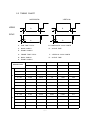
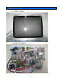
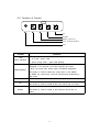
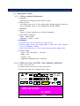
1
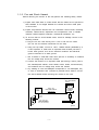
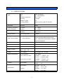
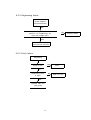
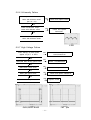
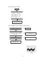
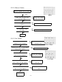
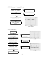
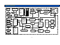
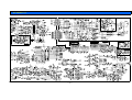
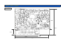
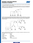
COLOR MONITOR
KT-2914DF
SERVICE
MANUAL
CONTENTS
1. PRECAUTIONS -------------------------------------------------- 2
2. PRODUCT SPECIFICATION -------------------------------- 5
3. OPERATING INSTRUCTION -------------------------------- 8
4. ADJUSTMENTS ------------------------------------------------- 10
5. TROUBLE SHOOTING GUIDE ---------------------------- 18
6. BLOCK DIAGRAM --------------------------------------------- 33
7. CONNECTING DIAGRAM ----------------------------------- 34
8. SCHEMATIC ----------------------------------------------------- 35
9. PRINT CIRCUIT BOARD ---------------------------------- 37
1.Precautions
1-1. Safety precautions
Warnings : Service should
not be attempted by anyone unfamiliar with the
necessary on this Monitor.
The followings are the necessary precautions to be observed before servicing.
1) For continued safety, do not attempt to modify the circuit board.
2) Disconnect the AC power before servicing.
3) When the chassis is operating, semiconductor heat sinks are potential
shock hazards.
1-1-1 Servicing the high voltage volume are CRT Warnings
A High Voltage volume replaced in the wrong direction may cause excessive
X-Ray emissions.
1) Adjust in order to 26.5KV with signal at Anode.
2)
When the troubleshooting a monitor with excessively High Voltage, avoid
being unnecessarily close to the monitor. Do not operate the monitor for
longer than is necessary to locate the cause of excessive voltage.
3)
Excessive High Voltage can produce potentially hazardous X-Ray RADIATION. To avoid such hazards, the high voltage must be above the
specified limit. The nominal value of the High voltage of this Monitor is
26.5KV ± 0.3KV at zero beam current(minimum brightness) under a 120V
AC power source. The High Voltage must not (under any circumstances)
exceed 29KV. Each time a monitor requires servicing, the High Voltage
should be checked following the High Voltage check procedure on this
manual. It is recommended the reading of the voltage be recorded as a
part of the service record. It is important to use an accurate and reliable
High Voltage meter.
4)
When the High Voltage regulator is operating properly, there is no possibility of an X-Ray problem.
5) The CRT is especially designed to prohibit X-ray emission. To ensure
continued X-ray protection, replace the CRT only with one that is the
same or equivalent type as the original.
6) Handle the CRT only when wearing shatterproof goggles and after completely.
7) Do not lift the CRT by the neck.
-2-
1-1-2. Fire and Shock Hazard
Before returning the monitor to the user,perform the following safety checks:
1) Inspect each lead dress to make certain that the leads are not pinched or
that hardware is not lodged between the chassis and other metal parts
in the monitor.
2) Inspect all protective devices such as nonmetallic control knobs, insulating
materials, cabinet backs, adjustment and compartment cover or shields
isolation resistor-capacitor networks, mechanical insulations, etc.
3) To be sure that no shock hazard exists, check for leakage current in the
following manner.
a. Plug the AC line cord directly into a 120 or 230 Volt AC outlet.
(Do not use an isolation transformer for this test)
b. Using two clip leads, connect a 1.5KΩ, 10Watt resistor paralleled by a
0.15Uf capacitor in serial with an exposed metal chassis part and a
known earth ground, such as an electrical conductor and electrical
ground connected to a earth ground.
c. Use a SSVM or VOM with 1000 ohms per-volt or sensitivity to measure
the AC voltage drop across the resistor.
d. Connect the resistor to an exposed metal part having a return path to
the chassis(metal cabinet, screw heads, knobs, shafts, escutcheon,etc)
and measure the AC voltage drop across the resistor.
e. Any reading of 5.25 volt RMS(this corresponds to 3.5 milliampere AC)
or more is excessive and
indicates a potential shock hazard. Correct
the shock hazard before returning the monitor to the user.
(READING SHOULD)
NOT BE ABOVE
0.5mA
DEVICE
UNDER
TEST
TEST ALL
EXPOSED METAL
SURFACES
LEAKAGE
CURRENT
TESTER
2-WIRE
CORD
ALSO TEST WITH
PLUG REVERSED
(USING AC ADAPTER
PLUG AS REQUIRED)
Earth
ground
Figure 1-1. Leakage Current Test Circuit
-3-
1-1-3. Product safety notices:
Some electrical and mechanical parts have special safety related characteristics
which are often not evident from visual inspection. The protection they give
may not be obtained by replacing them with components rated for higher voltage,wattage,etc. Parts that have special safety characteristics are identified by
△ on schematics and parts lists.
A substitute replacement that does not have the same safety characteristics
as the recommended replacement part might create shock, fire and or other
hazards. Product safety is under review continuously and new instructions
whenever appropriate.
1-2. Servicing Precautions
WARNING 1 : First read the "Safety Precaution" section of this manual. if
unforeseen circumstances create conflict between the servicing
precautions and safety precautions,always follow the safety
precautions.
WARNING 2 : A High Voltage volume replaced in the wrong direction may
cause excessive X-ray emissions.
WARNING 3 : An electrolytic capacitor installed with the wrong polarity might
explode.
1) Servicing precautions are printed on the chassis, and should be followed
closely
2) Always unplug the units AC power cord from the AC power source before
attempting to :(a) remove or reinstall any component or assembly, (b)
disconnect PCB plugs or connectors,(c) connect all test components in
parallel with an electrolytic capacitor.
3) after servicing, always check that the screws, components and wiring have
been correctly reinstalled. Make sure that the area around the serviced
part has not been damaged.
4) Check the insulation between the blades of the AC plug and accessible
conductive parts(examples:metal panels,input terminals and earphone jacks).
5) Never defeat any of the +B voltage interlocks. Do not apply AC power to
the unit(or any of its assemblies) unless all solid-state heat sinks are
correctly installed.
6) Always connect a test instruments ground lead to the instrument chassis
ground before connecting the lead; always remove the instruments lead last.
-4-
2. Product Specifications
2-1 SPECIFICATION
Tube
Dyna flat (option)
Size
73㎝ (29") diagonal
Viewable Image Size
60.5㎝ (24")
Dot Pitch
0.76㎜(H)
Deflection Angle
110°
Focusing Method
Single Focusing (static & dynamic)
Bandwidth
Maximum
50MHz
Scanning Frequency
Horizontal
15 ~ 40KHz
(Auto Scanning)
Vertical
50 ~ 120Hz
Display Area
Normal
550×400㎜
Maximum
580×410㎜
User Saving Mode
6 Modes
CDT
Microprocessor
Position,Size,Pincushion,Trapezoid,H/Vcorner,
User Control Display
Pin-B,Trapezoid,Parallel,Tilt,Moire,Zoom
OSD CONTROL
Color Temperature,Recall,Manual Degauss
Eng/Ger/Fra/Esp/Port
Display color
Color Temperature
9300°K, 6500°K, User Color
Resolution
Maximum Mode
800 X 600 @ 60Hz
Signal Input
Connect
15 pin D-sub(Female) or Option
Safety & EMC
Safety : cUL , CE
EMC : FCC , CE
Power
Free Voltage
AC 90-264V, 60 / 50±3Hz
Power Consumption
Nomal Operation
≤100 Watts
Input Current at 120V
Operating :≤ 1.5Amps rms.
Turn on
Input Current at 240V
Operating :≤ 0.8Amps rms.
Turn on
Linearity
:≤ 60Amps Peak.
Horizontal : 8%
Cross Pattern
Vertical
Temperature
Environment
:≤ 30Amps Peak.
: 10%
Operating : 0 to +40℃
Storage
Humidity
: -40 to +60℃
Operating : 10 to 85%
Storage
-5-
: 5 to 95%
2-2 D-SUB SIGNAL CABLE SPECIFICATION
* VGA / SVGA
CONNECTION
D-SUB 15PIN
IBM PC
WIRE COLOR
6P CONN 6P CONN
1
RED
RED COAX-IN
6P CONN-4
2
GREEN
GREEN COAX-IN
6P CONN-5
3
BLUE
BLUE COAX-IN
6P CONN-6
4
N.C
-
-
5
GND
BLACK
6P CONN-3
6
RED-GND
-
7
GREEN-GND
-
8
BLUE-GND
-
REMARK
RING WIRE
9
N.C
-
-
10
ID
-
-
11
N.C
-
-
12
SDA
-
-
13
H-SYNC (C/S)
ORANGE
6P CONN-1
14
V-SYNC
WHITE
6P CONN-2
15
SCL
-
-
SHELL
GND
-
RING WIRE
* CGA / EGA
CONNECTION
CGA SLOT
ZAMMA Spec_
WIRE COLOR
6P CONN 6P CONN
1 , A
H-SYNC
WHITE
6P CONN-1
16
V-SYNC
YELLOW
6P CONN-2
28 , f
GND & SHELL
BLACK
6P CONN-3
T
BLUE
BLUE
6P CONN-4
17
GREEN
GREEN
6P CONN-5
U
RED
RED
6P CONN-6
-6-
REMARK
2-3 TIMING CHART
HORIZONTAL
VERTICAL
VIDEO
C
D
S
R
Q
E
SYNC
P
B
A
O
A : LINE TIME TOTAL
B :HORIZONTAL SYNC WIDTH
C : BACK PORCH
D : ACTIVE TIME
E : FRONT PORCH
O : FRAME TIME TOTAL
P : VERTICAL SYNC WIDTH
Q : BACK PORCH
R : ACTIVE TIME
S : FRONT PORCH
CGA
DESCRPTION
H
V
EGA
VGA
SVGA
640 x 200
640 x 200
640 x 400
640*480
800*600
f KHz
15.750
15.750
24.827
31.469
37.88
A uS
63.5
63.5
40.28
31.778
26.40
B uS
8.671
8.672
3.04
3.813
3.20
C uS
7.272
7.272
3.8
1.907
2.20
D uS
40.836
40.836
30.399
25.422
20.00
E uS
6.72
6.72
3.04
0.636
1.00
POL.
POS
POS
POS
NEG
POS
f Hz
50
60.115
55.609
59.940
60.317
O mS
20.0
16.63
17.98
16.683
16.58
P mS
0.444
0.444
0.322
0.064
0.11
Q mS
0.825
0.825
1.26
1.048
0.61
R mS
18.603
15.302
16.111
15.253
15.84
S mS
0.128
0.06
0.282
0.318
0.03
POL.
POS
POS
POS
NEG
POS
-7-
3. Operating Instruction
3-1 FRONT FRAME
3.2 MAIN PCB ASS'Y
-8-
3-3. Function of Control
UP
DOWN
MENU (SELECT)
EXIT (DEGAUSSING)
LED
Control
LED
(Power Indicator)
Function
The light of power LED changes according to each state.
◎ on mode : Green LED.
◎ power saving mode : green LED blinking.
When you press this button, the MENU appears.The MENU will
disappear in 10 seconds if you don't operate any button.
MENU(Sellect)
When you press EXIT button again, the MENU disappears.
This button is used to select the control item on the MENU.
In MENU, the control item could be selected and unselected by
this button.
EXIT
UP
This button is used to exit the value of any selected control.
This button is used to increase the value of any selected control.
This button is used to locate to the next control item for select.
This button is used to decrease the value of any selected control.
DOWN
This button is used to locate to the previous control item for
select.
-9-
4.Adjustments
4-1. Adjustment Control
4-1-1. Before making Adjustments
1) Orientation
When servicing, always face the monitor to east.
2) Warm-up time
The monitor must be on for 30 minutes before starting alignment. Warm-up
time is especially critical in color temperature and white balance
adjustments.
3) Signal
Analog, 0.714Vp-p positive at 75Ω, internal termination.
4) High Voltage Adjustment
Signal : without signal
Adjustment : 26.5KV ± 0.5KV.
PROCEDURE
① Disconnect the AC line cord from the power source.
② Connect positive end of High Voltage probe to anode cap of CRT, negative
end of to GND(main chassis)
③ First of all Disconnect AC cord and than disconnect High voltage probe.
5) Screen Voltage
- signal : 640 * 480 (60Hz)
, Full white
- Bright : max
- Contrast : max
- Adjustment (SAMSUNG SDI) : 600±20V
4-1-2 TURN ON THE FACTORY OSD MANUAL METHOD
1) press on the "UP" key.
2) connect the AC line cord from the power source.
3) At this time OSD menu changed factory mode.
◑
HV AC
OSD
OSD
VF
BRIGHTNESS
31.4KHz
60Hz
- 10 -
i
4-2. Display Control Adjustment
Click on the "MENU" button (OSD MENU).
This menu is user's OSD manual.(user's manual)
◑
BRIGHTNESS
31.4KHz
60Hz
1) Click on the "MENU" button.
2) Click on the "UP"or "DOWN" and move any function control.
3) Press the "MENU(SELECT)" button.
4) "UP" or "DOWN" button is used to control the value of any function.
5) When you press exit button, the MENU disappears.
4-2-1 Screen center adjustment
width : 520mm
height : 400mm
signal : 640 * 480 (60Hz)
|A-B|≤ 4.0mm , |C-D|≤ 4.0mm
C
DISPLAY AREA
A
B
SQUARE CORNER
D
a) Horizontal size adjustment
adjustment : use to "H-SIZE", 520±3mm
- 11 -
b) Vertical size adjustment
adjustment : use to "V-SIZE", 400±3mm
c) Horizontal position adjustment
adjustment : use to "H-POS"
d) Vertical position adjustment
4-2-2 Trapezoid adjustment
frequency : all mode
signal pattern : cross hatch
A
A
B
B
|A-B|< 2.5mm
4-2-3 Pin balance adjustment
frequency : all mode
signal pattern : cross hatch
|D1|,|D2|≤1mm
D1
D2
D1
4-2-4 Parallelogram adjustment
frequency : all mode
signal pattern : cross hatch
5mm
- 12 -
4-2-5 Side pin-cushion adjustment
frequency : all mode
signal pattern : cross hatch
brightness : MIN (cut-off)
contrast : MAX
C2
D1
D2
C1
|C1|,|C2|≤2.0mm, |D1|,|D2|≤2.0mm
4-2-6 Tilt adjustment
frequency : all mode
signal pattern : cross hatch
brightness : MIN (cut-off)
contrast : MAX
4-2-7 Degaussing adjustment
Don't adjust the degaussing. Degaussing is possible in OSD
adjustment menu. After using this function once, You must
use again after at least 30minutes.
4-2-8 SAVE ADJUSTMENT CONDITION & REMOVE USER MODE.
- 13 -
4-3 Color adjustment
4-3-1 color temperature
※ Set condition
- measuring instrument : color analyzer (CA-100)
- frequency : 640 * 480 (60Hz)
- display pattern : full white , one square(25% window)
- brightness : cut off
- contrast : MAX
※ specification
- 9300K
x=0.281±0.02 , y=0.311±0.02
- 6500K
x=0.313±0.02 , y=0.329±0.02
4-3-2 color adjustment (9300K)
a) Back raster color adjustment
※ Set condition
- frequency : 640 * 480 (60Hz)
- display pattern : back raster pattern
- brightness : MIN (cut off)
- contrast : MAX
1.
2.
3.
4.
5.
Select factory mode.
Select COLOR TEMP with UP.DOWN key.
Select 9300K.
Adjust back raster brightness to 0.01~0.02(F/L) with VR601.
Select B-B with UP,DOWN adjust y=0.311 and do the next
selection with EXIT key.
6. Select R-B with UP,DOWN adjust x=0.281 and do the next
selection with EXIT key.
a) white balance / ACL adjustment
※ Set condition
- frequency : 640 * 480 (60Hz)
- display pattern : one square(25% window) , full white
- brightness : MIN (cut off)
- contrast : MAX
- 14 -
1.
2.
3.
4.
Select factory mode.
Select COLOR TEMP with UP,DOWN key.
Select 9300K.
Select B-G with UP,DOWN adjust y=0.311 and do the next
selection with EXIT key.
6. Select R-G with UP,DOWN adjust x=0.281 and do the next
selection with EXIT key.
7. Select contrast icon with UP,DOWN key, adjust contrast to
50~60f/l with UP,DOWN key.
front cabinet
20% window pattern
back raster
8. Select ACL key(A/C) in full white pattern and adjust ACL to
28~30f/l.
front cabinet
full white
back raster
※ attention : If 50f/l doesn't adjust in 20% window, adjust G-G
again with DOWN key.
4-3-3 color adjustment (6500K)
a) white balance adjustment
1. Select factory mode.
2. Select COLOR TEMP with UP,DOWN key.
3. Select 6500K.
- 15 -
4. Select B-G with UP,DOWN adjust y=0.329 and do the next
selection with EXIT key.
6. Select R-G with UP,DOWN adjust x=0.313 and do the next
selection with EXIT key.
4-3-4 brightness uniformity adjustment
※ set condition
- frequency : 640 * 480 (60Hz)
- display pattern : 9 ball pattern
- brightness : MIN (cut off)
- contrast : MAX
Measure nine brightness display in the screen.
front cabinet
4-3-5 Focus adjustment
※ set condition
- frequency : 640 * 480 (60Hz)
- display pattern : "H" character
- brightness : min (cut off)
- contrast : max
1. Adjust in focus of whole screen to be the best fitted with
FOCUS V/R in FBT.
4-3-6 PURITY adjustment
Purity is that unnecessary colors appear in the screen except
displayed color. Don't appear unnecessary colors divided with
the naked eye at a distance of 50㎝ from CRT surface.
- 16 -
※ set condition
- direction : east
- frequency : included timing chart
- display pattern : full white
- brightness : MIN (cut off) - display center
RED
GREEN
BLUE
Most suitable
x=0.640 ± 0.015
x=0.295 ± 0.015
x=0.142 ± 0.015
- 17 -
y=0.323 ± 0.015
y=0.594 ± 0.015
y=0.066 ± 0.015
5. TROUBLESHOOTING GUIDE
5-1. Troubleshooting Guide.
NOTES ;
1. If picture does not appear, fully rotate the brightness and contrast controls
clockwise.
2. Check the following circuits.
No raster appear : power circuit. Horizontal output circuit.
High voltage control circuit and output circuit.
High voltage develops but no raster appears : Video output circuit.
High voltage does not develop : Horizontal output circuit.
5-2-1. No Raster, No Video
No Power
Measure +80V output between
cathode of D110 and Ground.
YES
Does appear 80V DC?
Check the other secondary
outputs(+250V,+130V,+80V,+12V,
-12V,+12V,+6.3V ,5V Lines)
Does each output appear?
NO
Check and replace
Check and replace
F101,IC103
D104,D105,D106
Check Video and
Horizontal circuits
D108,IC103,IC101
5-2-2 S-Correction failure.
C/S TABLE
S1
S2
S3
1
~17K
L
L
L
Check S1,S2,S3 signals refer to
2
17~28K
L
L
H
S-correction table on the schematic
3
29~34K
L
H
H
4
34~40K
H
H
H
S1,S2,S3 signal are right
NO
Check and replace
at each frequency block
YES
Check and replace
Q704,707,709,703,706,708
- 18 -
IC103 1pin
5-2-3 Degaussing failure
Check degauss
Connector(CN102)
YES
Check output voltage at pin 12 of IC502
NO
(Normal : 0V, Degaussing: 5V)
Does DC voltage right?
YES
Check and replace
Q101,D101,RL101,R101
5-2-3 Purity failure
Degaussing
YES
Purity is O.K
Done
NO
Degaussing circuit
is right?
YES
Replace CRT and
verify purity
- 19 -
NO
Refer to 5-2-2
Replace IC502
5-2-4 Rotation Failure
Check tilt connection
(CN402)
IC 502 pin 35 output varies
NO
with different values?
Check and replace IC502
(DC 0V∼5V)
YES
Q403,Q401,Q402
NO
varies with different values?
Check and replace
Q403,Q401,Q402
YES
Check and replace
R-COIL of the CPT
5-2-5 Misconvergence Failure
Try readjusting convergence
NO
Is the convergence
YES
Done
now within spec?
NO
Readjusting convergence
YES
Done
NO
Is the convergence
now within spec?
NO
Change CPT and
readjusting convergence
- 20 -
5-2-6 H-Linearity Failure
Check pin 36 of IC502 output
varies with different value?
NO
Check and replace IC502
(DC 0V∼5V)
YES
Check Q702,Q701 output
NO
varies with different value?
Check and replace
Q702,Q701
YES
Check L304 output
varies with different value?
L304
5-2-7 High Voltage Failure
Does 900Vp-p fly back pulse
NO
appear on pin 1 of FBT?
Check and replace
Q704,D708,R716
YES
Q602,606 base driving pulse exist?
NO
Check +12V,Q602,606
YES
Q603 drain pulse exist?
NO
Check and replace Q603
YES
Q603 gate pulse exist?
NO
Check and replace D608,610
YES
Pin 9 of IC602 pulse exist?
NO
Q602,Q606 BASE
Replace IC602
FBT 1pin
- 21 -
5-2-8 User control Failure
Others
Check the voltage at pin 21
of IC502
Normal : 5V
Push the EXIT Key : 0.5V
Push the SEL Key : 1.5V
Push the UP Key : 3.5V
Push the DOWN Key : 2.5V
NO
Check and replace
R406,R408,R409,R410
5-2-10 Dynamic Focus Failure or poor Focus
Try Readjusting double Focus
YES
Done
NO
Check the wave form at SG601
Collector.Does appear parabola
NO
Check and replace
R712,T701
wave form?
NO
T701 wave form is right?
Check and replace
T701
YES
Replace the CPT
and verify focus
T701
- 22 -
5-2-10 Visible Retrace
NO Check Screen control voltage
Is Screen voltage (600±20V) right?
and FBT
YES
Does Q201 collector pulse
NO
Check 80V Line
(35Vp-p) exist?
YES
Does Q201 base drive
NO
Check The G1
wave form exist?
YES
Check and replace IC201
Q201 COLLECTOR
5-2-11 ACL Failure
Input full white pattern to monitor
YES
Check the voltage at pin 2 of IC502?
NO
(PWM WAVE FORM)
Check replace IC502
YES
Q605,Q607 base input exists?
NO
Check replace
Q605, 12V
YES
Check and replace pin
12 of the IC802?
IC502 2pin PWM
- 23 -
G1
5-2-12 Micom Failure
Does 5V appear Pin6 of IC502?
YES
X501
NO
IC502 Pin8 and pin8 wave
form are right?
Check and replace
X501,C512,C513
YES
NO
IC502 Pin 5 is over than
4.5Volt ?
Check and replace R507
YES
All input/output value
NO
are right?
Check and replace IC502
YES
Done
5-2-13 No Raster
Does fly back pulse at
NO
Check D712,D715
and 80V Line
collector of Q712 appear?
IC301 26pin
YES
NO
Check the Pin 26 of IC301.Does
Check and replace IC301
12Vp-p pulse appear?
YES
Does the wave form at
NO
pin 8 of T703 appear?
Check and replace
Q714,Q715,Q713
YES
Check the voltage PIN 7 of
IC701
T703 8pin
NO
Does 12V DC appear?
Check the
12V line
YES
Does the wave form at
NO
pin 4 of IC701 appear?
Check and replace
IC701
YES
Check heater
voltage 6.3V
- 24 -
5-2-14 No Video
Check signal cable
and connector
YES
IC802 Pin6,Pin8,Pin10 video
NO
input are right?
Check R,G,B Cable
conector
YES
IC802 Pin16,Pin19,Pin22
NO
Check and replace
IC802
video output are right?
YES
NO
Q806R,G,B
video output are right?
Check Q803 and
12V,80V Line
YES
R,G,B cathode wave
NO
forms are right?
Check R839R,G,B and
Q805R,G,B
YES
G2 voltage are right?
NO
(550±50V)
Check screen,CPT
socket, and FBT
YES
G1 voltage are right?
(-45±10V)
YES
Check and replace CPT
R,G,B Cathode wave form
- 25 -
5-2-15 Abnormal & Invariable H-size
IC 301 Pin24 output
NO
parabola level variable?
Check and replace IC301
and 12V,80V Line?
YES
NO
Does T303 Pin8 pulse
Check and replace T303?
is appear??
YES
Check some parts around
T702 are they OK?
YES
Check and replace
Q710?
IC301 24pin
5-2-16 OSD failure
Check CN401
YES
IC801 Pin5, Pin10 wave
NO
Check and replace
forms are right?
Q802,Q803
YES
V-FLY
When you click on the
"MENU" botton. IC801
NO
Pin13,Pin14,Pin15,Pin12
Check and replace
IC801,5V Line
wave forms are right?
YES
When you click on the
"MENU" botton. IC502
Pin10,Pin11, wave forms
NO
Check IC502 and
SDA,SCL Line
are right?
YES
H-FLY
Check and replace IC802
- 26 -
5-2-17 V-deflection failure
Does 12V DC appear at
Pin2 of IC201?
NO
Does -12V DC appear at
Refer to No power supply
Pin5 of IC201?
YES
IC 301 Pin 13,Pin 23
NO
output exist?
Check and replace IC301?
YES
IC 502 Pin 33 output
exist?
NO
Check and replace IC502?
YES
Check and replace IC201?
IC201 5 pin
IC201 1 pin
- 27 -
7. BLOCK DIAGRAM
AC
INLET
SOCKET
SWITCHING
IC ( 6S1265R)
5V
6.3V
12V
14V
-14V
85V
130V
250V
SWITCHING
MODE
LINE
FILTER
DEGAUSSING
BRIDGE
DIODE
POWER
SUPPLY
FEEDBACK
CONTROL
R,G,B
INPUT
VIDEO AMP
( TDA4887 )
OSD
PROCESSOR
( WT6802 )
I² C
VIDEO
OUTPUT
CRT
CUT-OFF
CONTROL
I² C
I² C
DPMS OUTPUT
- SUSPEND
- OFF
MICRO
LED
CONTROL
CONTROLLER
UNIT
H/V SYNC
INPUT
( WT62P1 )
ADJUST KEY
TILT COIL
DDC 2BI
- H/V SIZE
- H/V POSI
- S-PIN
- TRAP
- PARA
- PIN BAL
- ACL
- TILT
- DEG
VERTICAL
OUTPUT
( TDA8172 )
-HIGH
VOLTAGE
-H.FOCUS
-V.FOCUS
-SCREEN
FLYBACK
OUTPUT
STAGE
TRANS
DEFLECTION
S-CORRECTI
ON CIRCUIT
(S1~S4)
HIGH VOLTAGE
PROTECTION CIRCUIT
DEFLECTION YOKE
HORIZONTAL
DRIVE
CIRCUIT
I²C
TLIT
TLIT
CONTROL
I² C
SYNC
PROCESSOR
(STV6888
or
TDA9116 )
DYNAMIC
FOCUS
CIRCUIT
BRIGHT
CONTROL
HIGH VOLTAGE
DRIVE CIRCUIT
- 28 -
HIGH
VOLTAGE
OUTPUT
STAGE
HIGH
VOLTAGE
REGULATION
7. CONNECTING DIAGRAM
* CN407 & CN409orCN406= GGA/EGA
* CN405 & CN404= VGA/SVGA
CN407
CN405
C
N
8
0
1
CN404
CN409
CN406
CN401
CN411
CN807
SIGNAL IN
CN401
- 29 -
8. SCHEMATIC
- 30 -
9. PRINT CIRCUIT BOARD
10-1 MAIN
247mm
247mm
- 31 -
9. PRINT CIRCUIT BOARD
10-2 VIDEO
98mm
128mm
25mm
150mm
- 32 -