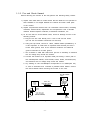
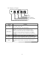
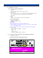
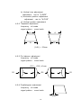
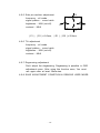
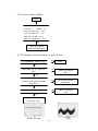
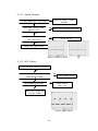
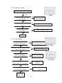
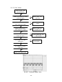
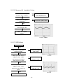
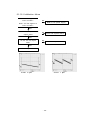
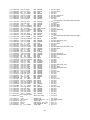
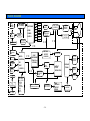
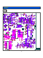
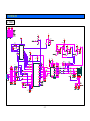
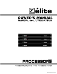
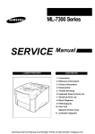
1
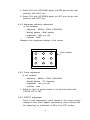
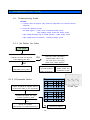
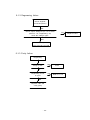
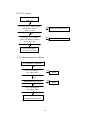
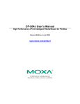
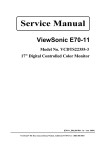
COLOR CRT MONITOR
SERVICE
DOC. NO
KT-XX82X-SM
DATE
2004 .02. 02
REV. NO
0
REV. DATE
-
MANUAL
KT-1982F / KT-1982DF
KT-1782F / KT-1782DF
KT-2182F
KORTEK CORPORATION
CONTENTS
1. PRECAUTIONS -------------------------------------------------- 3
2. PRODUCT SPECIFICATION -------------------------------- 6
3. OPERATING INSTRUCTION -------------------------------- 9
4. ADJUSTMENTS ------------------------------------------------- 11
5. TROUBLE SHOOTING GUIDE ---------------------------- 19
6. PART LIST ------------------------------------------------------- 29
7. BLOCK DIAGRAM --------------------------------------------- 34
8. CONNECTING DIAGRAM ----------------------------------- 35
9. SCHEMATIC ----------------------------------------------------- 36
10. PRINT CIRCUIT BOARD ---------------------------------- 38
-2-
1.Precautions
1-1. Safety precautions
Warnings : Service should
not be attempted by anyone unfamiliar with the
necessary on this Monitor.
The followings are the necessary precautions to be observed before servicing.
1) For continued safety, do not attempt to modify the circuit board.
2) Disconnect the AC power before servicing.
3) When the chassis is operating, semiconductor heat sinks are potential
shock hazards.
1-1-1 Servicing the high voltage volume are CRT Warnings
A High Voltage volume replaced in the wrong direction may cause excessive
X-Ray emissions.
1) Adjust in order to 26KV with signal at Anode.
2)
When the troubleshooting a monitor with excessively High Voltage, avoid
being unnecessarily close to the monitor. Do not operate the monitor for
longer than is necessary to locate the cause of excessive voltage.
3)
Excessive High Voltage can produce potentially hazardous X-Ray RADIATION. To avoid such hazards, the high voltage must be above the
specified limit. The nominal value of the High voltage of this Monitor is
26KV ± 0.3KV at zero beam current(minimum brightness) under a 120V
AC power source. The High Voltage must not (under any circumstances)
exceed 29KV. Each time a monitor requires servicing, the High Voltage
should be checked following the High Voltage check procedure on this
manual. It is recommended the reading of the voltage be recorded as a
part of the service record. It is important to use an accurate and reliable
High Voltage meter.
4)
When the High Voltage regulator is operating properly, there is no possibility of an X-Ray problem.
5) The CRT is especially designed to prohibit X-ray emission. To ensure
continued X-ray protection, replace the CRT only with one that is the
same or equivalent type as the original.
6) Handle the CRT only when wearing shatterproof goggles and after completely.
7) Do not lift the CRT by the neck.
-3-
1-1-2. Fire and Shock Hazard
Before returning the monitor to the user,perform the following safety checks:
1) Inspect each lead dress to make certain that the leads are not pinched or
that hardware is not lodged between the chassis and other metal parts
in the monitor.
2) Inspect all protective devices such as nonmetallic control knobs, insulating
materials, cabinet backs, adjustment and compartment cover or shields
isolation resistor-capacitor networks, mechanical insulations, etc.
3) To be sure that no shock hazard exists, check for leakage current in the
following manner.
a. Plug the AC line cord directly into a 120 or 230 Volt AC outlet.
(Do not use an isolation transformer for this test)
b. Using two clip leads, connect a 1.5KΩ, 10Watt resistor paralleled by a
0.15Uf capacitor in serial with an exposed metal chassis part and a
known earth ground, such as an electrical conductor and electrical
ground connected to a earth ground.
c. Use a SSVM or VOM with 1000 ohms per-volt or sensitivity to measure
the AC voltage drop across the resistor.
d. Connect the resistor to an exposed metal part having a return path to
the chassis(metal cabinet, screw heads, knobs, shafts, escutcheon,etc)
and measure the AC voltage drop across the resistor.
e. Any reading of 5.25 volt RMS(this corresponds to 3.5 milliampere AC)
or more is excessive and
indicates a potential shock hazard. Correct
the shock hazard before returning the monitor to the user.
(READING SHOULD)
NOT BE ABOVE
0.5mA
DEVICE
UNDER
TEST
TEST ALL
EXPOSED METAL
SURFACES
LEAKAGE
CURRENT
TESTER
2-WIRE
CORD
ALSO TEST WITH
PLUG REVERSED
(USING AC ADAPTER
PLUG AS REQUIRED)
Earth
ground
Figure 1-1. Leakage Current Test Circuit
-4-
1-1-3. Product safety notices:
Some electrical and mechanical parts have special safety related characteristics
which are often not evident from visual inspection. The protection they give
may not be obtained by replacing them with components rated for higher voltage,wattage,etc. Parts that have special safety characteristics are identified by
△ on schematics and parts lists.
A substitute replacement that does not have the same safety characteristics
as the recommended replacement part might create shock, fire and or other
hazards. Product safety is under review continuously and new instructions
whenever appropriate.
1-2. Servicing Precautions
WARNING 1 : First read the "Safety Precaution" section of this manual. if
unforeseen circumstances create conflict between the servicing
precautions and safety precautions,always follow the safety
precautions.
WARNING 2 : A High Voltage volume replaced in the wrong direction may
cause excessive X-ray emissions.
WARNING 3 : An electrolytic capacitor installed with the wrong polarity might
explode.
1) Servicing precautions are printed on the chassis, and should be followed
closely
2) Always unplug the units AC power cord from the AC power source before
attempting to :(a) remove or reinstall any component or assembly, (b)
disconnect PCB plugs or connectors,(c) connect all test components in
parallel with an electrolytic capacitor.
3) after servicing, always check that the screws, components and wiring have
been correctly reinstalled. Make sure that the area around the serviced
part has not been damaged.
4) Check the insulation between the blades of the AC plug and accessible
conductive parts(examples:metal panels,input terminals and earphone jacks).
5) Never defeat any of the +B voltage interlocks. Do not apply AC power to
the unit(or any of its assemblies) unless all solid-state heat sinks are
correctly installed.
6) Always connect a test instruments ground lead to the instrument chassis
ground before connecting the lead; always remove the instruments lead last.
-5-
2. Product Specifications
2-1 SPECIFICATION
CDT
KT-1982F
KT-1982DF
KT-1782F
KT-1782DF
KT-2182F
Tube
19"No rmal flat
19"Dyna flat
17"Dyna flat
17"No rmal flat
21"No rmal flat
Tube Size(Diagonal)
494 .8mm
494 .8mm
444 .0mm
444 .0mm
548 .0mm
Viewabl e S ize (Dia gonal )
457 .2mm
457 .2mm
406 .7mm
401 .0mm
508 .0mm
Dot Pitch
0.26㎜ (H)
0.25㎜ (H)
0.25㎜ (H)
0.28㎜ (H)
0.25㎜ (H)
Deflection Angle
90°
90°
90°
90°
90°
Focusing Method
Double
Double
Double
Double
Double
Normal (H*V)
360 *27 0
360 *27 0
320 *24 0
320 *24 0
400 *30 0
Maximum (H*V)
370 *27 8
370 *27 8
330 *24 8
330 *24 8
410 *30 8
Maximum
140MHz
Display Area (mm)
Bandwidth
Scanning Frequency Horizontal
30-82KHz
(Auto Scanning)
Vertical
50-120Hz
Microprocessor
User Saving Mode 13 Modes
Digital
Position,Size,Pincushion,Trapezoid,H/Vcorner,
User Control
Pin-B,Trapezoid,Parallel,Tilt,Moire,Zoom
Display
Color Temperature,Recall,Manual Degauss
Language
Eng/Ger/Fra/Esp/Port
Display color
Color Temperature 9300 °
K, 6500°
K, User Color
Resolution
Maximum Mode
1280 X 1024 @ 75Hz
Signal Input
Connect
15 pin D-sub(Female) or Option
Safety
UL,CSA,TUV,CB,DHHS
EMC
FCC,CE
Voltage
AC 90-264V, 60 / 50 ±3Hz
Safety & EMC
Power
Power Consumption Nomal Operation
Input Current
at 120V
Input Current
at 240V
Linearity
Cross Pattern
Temperature
Environment
≤100 Watts
Operating :≤ 1.5Amps
Turn on
rms.
:≤ 60Amps Peak.
Horizontal : 5%
Vertical
: 5%
Operating : 0 to +40℃
Storage
Humidity
:≤ 30Amps Peak.
Operating :≤ 0.8Amps
Turn on
rms.
: -40 to +60℃
Operating : 10 to 85%
Storage
: 5 to 95%
-6-
2-2 D-SUB SIGNAL CABLE SPECIFICATION
PIN NO
1
2
PIN NAME
RED
GREEN
3
4
5
BLUE
GND
GND (DDC)
6
7
8
R-GND
G-GND
B-GND
9
10
11
N.C
SELF RASTER
GND
12
13
14
SDA (DDC)
H-SYNC
V-SYNC
15
SCL (DDC)
1
6
7
11
-7-
2
3
8
12
4
9
13
5
10
14
15
2-3 TIMING CHART
HORIZONTAL
VERTICAL
VIDEO
C
D
Q
E
S
R
SYNC
B
P
A
O
A : LINE TIME TOTAL
B :HORIZONTAL SYNC WIDTH
C : BACK PORCH
D : ACTIVE TIME
E : FRONT PORCH
O : FRAME TIME TOTAL
P : VERTICAL SYNC WIDTH
Q : BACK PORCH
R : ACTIVE TIME
S : FRONT PORCH
I.B.M
DESCRPTION
720*400
640*480
VESA
1024*768
640*480
800*600
800*600
800*600
1024*768
800*600
1024*768
1280*1024
1024*768
1280*1024
1024*768
(I)
H
f KHz
31.469
31.469
35.52
37.860
37.88
46.875
48.077
48.363
53.674
56.476
63.702
68.677
79.976
81.400
A
uS
31.778
31.778
28.15
26.413
26.40
21.333
20.800
20.677
18.631
17.707
15.698
14.561
12.504
12.285
B
uS
3.813
3.813
3.92
1.270
3.20
1.616
2.400
2.092
1.138
1.813
1.358
1.016
1.067
0.988
uS
1.907
1.907
1.25
4.603
2.20
3.232
1.280
2.262
2.702
1.920
1.812
2.201
1.837
1.624
D
uS
25.422
25.422
22.80
20.317
20.00
16.162
16.000
15.754
14.222
13.653
12.075
10.836
9.481
9.037
E
uS
0.636
0.636
0.18
0.762
1.00
0.323
1.120
0.369
0.569
0.320
0.453
0.508
0.119
0.635
NEG
NEG
POS
POS
POS
POS
POS
NEG
POS
NEG
NEG
POS
NEG
POS
59.940
86.906
72.809
60.317
75Hz
72.188
60.00
85.061
70.00
60.00
84.997
75.025
100.00
C
POL.
V
f
Hz
70.087
O
mS
14.268
16.683
11.50
13.735
16.58
13.333
13.853
16.667
11.756
14.272
16.640
11.765
13.329
10.000
P
mS
0.064
0.064
0.113
0.079
0.11
0.064
0.125
0.124
0.056
0.106
0.047
0.044
0.038
0.037
Q
mS
1.080
1.048
0.563
0.740
0.61
0.448
0.478
0.60
0.503
0.513
0.471
0.524
0.475
0.516
R mS
12.711
15.253
10.81
12.678
15.84
12.8
12.480
15.88
11.179
13.599
16.075
11.183
12.804
9.435
0.413
0.318
0.014
0.238
0.03
0.021
0.770
0.062
0.019
0.053
0.047
0.015
0.013
0.012
POS
NEG
POS
POS
POS
POS
POS
NEG
POS
NEG
NEG
POS
POS
POS
S
mS
POL.
-8-
3. Operating Instruction
3-1 FRONT FRAME
KORTEK
STANDARD FRAME
(X-FRAM)
3.2 MAIN PCB ASS'Y
MAIN PCB
SOCKET PCB
CONTROL PCB
-9-
3-3. Function of Control
UP
DOWN
MENU (SELECT)
EXIT (DEGAUSSING)
LED
Control
LED
(Power Indicator)
Function
The light of power LED changes according to each state.
◎ on mode : Green LED.
◎ power saving mode : green LED blinking.
When you press this button, the MENU appears.The MENU will
disappear in 10 seconds if you don't operate any button.
MENU(Sellect)
When you press EXIT button again, the MENU disappears.
This button is used to select the control item on the MENU.
In MENU, the control item could be selected and unselected by
this button.
EXIT
UP
This button is used to exit the value of any selected control.
This button is used to increase the value of any selected control.
This button is used to locate to the next control item for select.
This button is used to decrease the value of any selected control.
DOWN
This button is used to locate to the previous control item for
select.
- 10 -
4.Adjustments
4-1. Adjustment Control
4-1-1. Before making Adjustments
1) Orientation
When servicing, always face the monitor to east.
2) Warm-up time
The monitor must be on for 30 minutes before starting alignment. Warm-up
time is especially critical in color temperature and white balance
adjustments.
3) Signal
Analog, 0.714Vp-p positive at 75Ω, internal termination.
4) High Voltage Adjustment
Signal : without signal
Adjustment : 26KV ± 0.3KV.
PROCEDURE
① Disconnect the AC line cord from the power source.
② Connect positive end of High Voltage probe to anode cap of CRT, negative
end of to GND(main chassis)
③ First of all Disconnect AC cord and than disconnect High voltage probe.
5) Screen Voltage
- signal : 1024 x 768 (48KHz)
, Full white
- Bright : max
- Contrast : max
- Adjustment (SAMSUNG SDI) : 580 ±10V
4-1-2 TURN ON THE FACTORY OSD MANUAL METHOD
1) press on the "UP" key.
2) connect the AC line cord from the power source.
3) At this time OSD menu changed factory mode.
◑
HV AC
OSD
OSD
VF
BRIGHTNESS
31.4KHz
60Hz
- 11 -
i
4-2. Display Control Adjustment
Click on the "MENU" button (OSD MENU).
This menu is user's OSD manual.(user's manual)
◑
BRIGHTNESS
31.4KHz
60Hz
1) Click on the "MENU" button.
2) Click on the "UP"or "DOWN" and move any function control.
3) Press the "MENU(SELECT)" button.
4) "UP" or "DOWN" button is used to control the value of any function.
5) When you press exit button, the MENU disappears.
4-2-1 Screen center adjustment
width : 21"(400mm),19"(360mm),17"(320mm)
height : 21"(300mm),19"(270mm),17"(240mm)
signal : 1024 x 768 (48KHz)
|A-B|≤ 4.0mm , |C-D|≤ 4.0mm
C
DISPLAY AREA
A
B
D
a) Horizontal size adjustment
adjustment : use to "H-SIZE"
- 12 -
SQUARE CORNER
b) Vertical size adjustment
adjustment : use to "V-SIZE"
c) Horizontal position adjustment
adjustment : use to "H-POS"
d) Vertical position adjustment
4-2-2 Trapezoid adjustment
frequency : all mode
signal pattern : cross hatch
A
A
B
B
|A-B|< 2.5mm
4-2-3 Pin balance adjustment
frequency : all mode
signal pattern : cross hatch
|D1|,|D2|≤1mm
D1
D2
D1
4-2-4 Parallelogram adjustment
frequency : all mode
signal pattern : cross hatch
5mm
- 13 -
4-2-5 Side pin-cushion adjustment
frequency : all mode
signal pattern : cross hatch
brightness : MIN (cut-off)
contrast : MAX
C2
D1
D2
C1
|C1|,|C2|≤2.0mm, |D1|,|D2|≤2.0mm
4-2-6 Tilt adjustment
frequency : all mode
signal pattern : cross hatch
brightness : MIN (cut-off)
contrast : MAX
4-2-7 Degaussing adjustment
Don't adjust the degaussing. Degaussing is possible in OSD
adjustment menu. After using this function once, You must
use again after at least 30minutes.
4-2-8 SAVE ADJUSTMENT CONDITION & REMOVE USER MODE.
- 14 -
4-3 Color adjustment
4-3-1 color temperature
※ Set condition
- measuring instrument : color analyzer (CA-100)
- frequency : 48KHz / 60Hz (1024 x 768)
- display pattern : full white , one square(20% window)
- brightness : cut off
- contrast : MAX
※ specification
- 9300K
x=0.281±0.02 , y=0.311±0.02
- 6500K
x=0.313±0.02 , y=0.329±0.02
4-3-2 color adjustment (9300K)
a) Back raster color adjustment
※ Set condition
- frequency : 48KHz / 60Hz (1024 x 768)
- display pattern : back raster pattern
- brightness : MIN (cut off)
- contrast : MAX
1. Select factory mode.
2. Select COLOR TEMP with UP.DOWN key.
3. Select 9300K.
4. Adjust back raster brightness to 0.2~0.8(F/L) with VR701.
5. Select B-B with UP,DOWN adjust y=0.311 and do the next
selection with EXIT key.
6. Select R-B with UP,DOWN adjust y=0.281 and do the next
selection with EXIT key.
a) white balance / ACL adjustment
※ Set condition
- frequency : 48KHz / 60Hz (1024 x 768)
- display pattern : one square(20% window) , full white
- brightness : MIN (cut off)
- contrast : MAX
- 15 -
1. Select factory mode.
2. Select COLOR TEMP with UP,DOWN key.
3. Select 9300K.
4. Select B-G with UP,DOWN adjust y=0.311 and do the next
selection with EXIT key.
6. Select R-G with UP,DOWN adjust y=0.281 and do the next
selection with EXIT key.
7. Select contrast icon with UP,DOWN key, adjust contrast to
50~60f/l with UP,DOWN key.
front cabinet
20% window pattern
back raster
8. Select ACL key(A/C) in full white pattern and adjust ACL to
28~30f/l.
front cabinet
full white
back raster
※ attention : If 50f/l doesn't adjust in 20% window, adjust G-G
again with DOWN key.
4-3-3 color adjustment (6500K)
a) white balance adjustment
1. Select factory mode.
2. Select COLOR TEMP with UP,DOWN key.
3. Select 6500K.
- 16 -
4. Select B-G with UP,DOWN adjust y=0.329 and do the next
selection with EXIT key.
6. Select R-G with UP,DOWN adjust y=0.313 and do the next
selection with EXIT key.
4-3-4 brightness uniformity adjustment
※ set condition
- frequency : 48KHz / 60Hz (1024x768)
- display pattern : 9ball pattern
- brightness : MIN (cut off)
- contrast : MAX
Measure nine brightness display in the screen.
front cabinet
4-3-5 Focus adjustment
※ set condition
- frequency : 48KHz / 60Hz (1024x768)
- display pattern : "H" character
- brightness : min (cut off)
- contrast : max
1. Adjust in focus of whole screen to be the best fitted with
FOCUS V/R in FBT.
4-3-6 PURITY adjustment
Purity is that unnecessary colors appear in the screen except
displayed color. Don't appear unnecessary colors divided with
the naked eye at a distance of 50㎝ from CRT surface.
- 17 -
※ set condition
- direction : east
- frequency : included timing chart
- display pattern : full white
- brightness : MIN (cut off) - display center
Most suitable
RED
GREEN
BLUE
x=0.640 ± 0.015
x=0.295 ± 0.015
x=0.142 ± 0.015
- 18 -
y=0.323 ± 0.015
y=0.594 ± 0.015
y=0.066 ± 0.015
5. TROUBLESHOOTING GUIDE
5-1. Troubleshooting Guide.
NOTES ;
1. If picture does not appear, fully rotate the brightness and contrast controls
clockwise.
2. Check the following circuits.
No raster appear : power circuit. Horizontal output circuit.
High voltage control circuit and output circuit.
High voltage develops but no raster appears : Video output circuit.
High voltage does not develop : Horizontal output circuit.
5-1-1. No Raster, No Video
No Power
Measure +80V output between
cathode of D120 and Ground.
YES
Does appear 80V DC?
NO
Check the other secondary
outputs(+200V,+80V,+14V,
-14V,+12V,+6.3V ,5V Lines)
Does each output appear?
Check and replace
Check and replace
F801,D801,IC811,IC812
D115,D121,D120
Check Video and
Horizontal circuits
D107,IC103,IC101
5-1-2 S-Correction failure.
C/S TABLE
S1 S2 S3 S4
1
~31K
L
L
L
L
Check S1,S2,S3,S4 signals refer to
2
34~36K
L
L
H
H
S-correction table on the schematic
3
37~42K
L
H
L
H
4
43~50K
H
L
H
H
5
51~58K
H
H
L
L
S1,S2,S3,S4 signal are right
6
59~66K
H
H
L
H
at each frequency block
7
67~73K
H
H
H
L
8
74K~
H
H
H
H
YES
Check and replace
Q307,309,311,313,306,308,310,312
NO
- 19 -
Check and replace
IC106 1pin
5-1-3 Degaussing failure
Check degauss
Connector(CN101)
YES
Check output voltage at pin 12 of IC501
NO
(Normal : 0V, Degaussing: 5V)
Does DC voltage right?
YES
Check and replace
Q101,D101,RL101,R106
5-1-3 Purity failure
Degaussing
YES
Purity is O.K
Done
NO
Degaussing circuit
is right?
YES
Replace CRT and
verify purity
- 20 -
NO
Refer to 5-1-2
Replace IC501
5-1-4 Tilt Failure
Check tilt connection
(CN100)
IC 501 pin 35
output varies
NO
with different values?
Check and replace IC501
(DC 0V~5V)
YES
IC105 pin 10,11 output
NO
varies with different values?
Check and replace IC105
(DC 1.5V~7.5V)
.
YES
Check and replace
R-COIL of the CDT
6-1-6 Misconvergence Failure
Try readjusting convergence
NO
Is the convergence
YES
Done
now within spec?
NO
Readjusting convergence
YES
Done
NO
Is the convergence
now within spec?
NO
Change CDT and
readjusting convergence
- 21 -
6-1-7 H-Linearity Failure
Check pin 36 of IC501 output
NO
varies with different value?
(DC 0V~5V)
Check and replace IC501
YES
Check pin 7,8 of IC105
NO
output varies with different
Check and replace IC105
value? (DC 1V ~ 6V)
YES
Check L304 output
varies with different value?
L304
6-1-8 High Voltage Failure
Does 900V p-p fly back pulse
Check and replace
NO
appear on pin 1 of FBT?
Q704,D708,R716
YES
Q701,703 base driving pulse exist?
NO
Check +12V,Q701,703
YES
Q704 drain pulse exist?
NO
Check and replace Q704
YES
NO
Q704 gate pulse exist?
Check and replace D708,709
YES
Pin 9 of IC701 pulse exist?
NO
Replace IC701
Q701,Q703 BASE
FBT 1pin
- 22 -
5-1-9 User control Failure
Others
Check the voltage at pin 21
of IC501
Normal : 5V
Push the EXIT Key : 0.5V
Push the SEL Key : 1.5V
Push the UP Key : 3.5V
Push the DOWN Key : 2.5V
NO
Check and replace
R401,R403,R405,R406
5-1-10 Dynamic Focus Failure or poor Focus
Try Readjusting double Focus
YES
Done
NO
Does IC301 32 pin wave form
NO
exist?
Check and replace
IC301
YES
Check the wave form at Q705
NO
Collector.Does appear parabola
Check and replace
R725,C720
wave form?
NO
T702 wave form is right?
Check and replace
T702
YES
Replace the CRT
and verify focus
IC301 32 pin
T702
- 23 -
5-1-11 Visible Retrace
NO
Is G2 voltage (580 ±50V) right?
Check G2 control
voltage
and FBT
YES
Does Q201 collector pulse
NO
(35Vp-p) exist?
Check 80V Line and D719,C726
YES
Does Q201 base drive
NO
Check The G1
wave form exist?
YES
Check and replace IC201
Q201 COLLECTOR
5-1-12 ACL Failure
Input full white pattern to monitor
YES
Check the voltage at pin 2 of IC501?
NO
(PWM WAVE FORM)
Check replace IC501
YES
Q707 base input exists?
NO
Check replace
Q707, 12V
YES
Check and replace pin
12 of the IC802?
IC501 2pin PWM
- 24 -
G1
5-1-13 Micom Failure
Does 5V appear Pin6 of IC501?
YES
X501
NO
IC501 Pin8 and pin8 wave
form are right?
Check and replace
X501,C516,C517
YES
NO
IC501 Pin 5 is over than
4.5Volt ?
Check and replace R517
YES
All input/output value
NO
are right?
Check and replace IC502
YES
Done
5-1-14 No Raster
Does flyback pulse at
NO
Check D309,D311
collector of Q302 appear?
and 80V Line
IC301 26pin
YES
Check the Pin 26 of IC301.Does
NO
12Vp-p pulse appear?
Check and replace IC301
YES
Does the wave form at
pin 8 of T302 appear?
NO
Check and replace
Q304,Q303,Q305
YES
Check the voltage PIN 7 of
IC302
T302 8pin
NO
Does 12V DC appear?
Check the
12V line
YES
Does the wave form at
NO
pin 4 of IC302 appear?
Check and replace
IC302
YES
Check heater
voltage 6.3V
- 25 -
5-1-15 No Video
Check signal cable
and connector
YES
IC802 Pin5,Pin8,Pin10 video
NO
input are right?
Check IC201 and
12V Line
YES
IC802 Pin21,Pin24,Pin26
NO
Check and replace
IC802
video output are right?
YES
IC803 Pin5,Pin3,Pin1
NO
video output are right?
Check IC803 and
12V,80V Line
YES
R,G,B cathode wave
NO
forms are right?
Check D805~807 and
D814~D816
YES
G2 voltage are right?
NO
(580±50V)
Check G2,CDT
socket,FBT
YES
G1 voltage are right?
(-45 ±10V)
YES
Check and replace CRT
B-OUT Cathode wave form
- 26 -
5-1-16 Abnormal & Invariable H-size
IC 301 Pin24 output
NO
parabola level variable?
Check and replace IC301
and 12V,80V Line?
YES
NO
Does T303 Pin8 pulse
Check and replace T303?
is appear??
YES
Check some parts around
T301 are they OK?
YES
Check and replace
Q314?
IC301 24pin
5-1-17 OSD failure
Check CN801
YES
IC801 Pin5, Pin10 wave
NO
Check and replace
forms are right?
Q801,Q802
YES
V-FLY
When you click on the
"MENU" botton. IC801
NO
Pin13,Pin14,Pin15,Pin12
Check and replace
IC801,5V Line
wave forms are right?
YES
When you click on the
"MENU" botton. IC501
Pin7,Pin8, wave forms are
NO
Check IC501 and
SDA,SCL Line
right?
YES
H-FLY
Check and replace IC802
- 27 -
5-1-18 V-deflection failure
Does 14V DC appear at
Pin2 of IC201?
NO
Does -14V DC appear at
Refer to No power supply
Pin5 of IC201?
YES
IC 301 Pin 13,Pin 23
NO
output exist?
Check and replace IC301?
YES
IC 501 Pin 33 output
exist?
NO
Check and replace IC501?
YES
Check and replace IC201?
IC201 6 pin
IC201 1 pin
- 28 -
6. PART LIST
6-1. KT-1982F PART PIST
1
1
1
1
1
1
1
1
1
1
1
1
1
1
1
1
1
1
1
1
1
1
1
1
1
1
1
1
1
1
1
1
1
1
1
1
1
1
1
1
1
1
1
1
1
1
1
1
1
1
1
1
1
1
1
1
1
1
1
1
1
1
1
1
1
1
1
1
1
1
02-198221180
27-41023R38T
26-M22R0103T
27-24040226T
27-23040223T
23-70B90153T
27-23040103T
27-24040473T
23-70B90103T
23-70B90223T
23-109C0224T
26-F20A0102B
27-24050103B
27-2804033JT
23-39G90154X
23-39G90104X
26-822R0104T
27-23030338T
27-2403047FB
23-70B90104T
23-70B90472T
26-R20A0221T
27-23020018T
27-2304010BB
23-109C0105T
26-81590101T
27-23030108T
23-27B90102B
27-23024R78T
23-109A0474T
26-P20A0331T
23-70B90154T
27-23030478T
26-81590121T
23-70B90332T
23-70B90103T
23-70B90473T
26-81590681T
23-33R90272B
23-70B90273T
23-70B90222T
26-M20A0102T
26-81590331T
26-822R0103T
23-32F90824B
23-32F90564B
23-32F90254B
23-32F90104B
23-32F90274B
26-P20A0101T
26-820A0102T
26-81590033T
26-81590022T
27-23030228T
23-70B90563T
26-R20A0152T
23-33R90701B
27-24022R2KT
27-2304022BB
27-4402001BT
26-R20A0221T
23-34F90103B
23-10FA0104T
27-2403010FB
49-000002X00
52-700006XXX
52-700007XXX
48-051303500
48-050405000
49-0526706XX
KT-1982F
SMBP 50V 3.3 UF T/P
DC500V-F-103PF(Z)T/P
KMG 35V 220 UF T/P
KME 16V 220 UF T/P
100V 153J T/P(DI,OY)
KME 16V 100 UF T/P
KMG 16V 470 UF T/P
100V 103J T/P(DI,OY)
100V 223J T/P
63V 224K T/P (DW,OY)
AC250V-B-102PF(K)
KMG 16V 1000 UF
KMH 400VN 330 UF
BOX AC 275V 154UF
BOX AC 275V 104UF
DC50V-F-104PF(Z) T/P
KME 50V 33
UFT/P
KMG 250V 47
UF
100V 104J T/P(DI,OY)
100V 472J T/P
DC2KV-B-221PF(K) T/P
KME 50V 1
UFT/P
KMG 100V 100 UF
63V 105K T/P (DW,OY)
DC50V-SL-101PF(J)T/P
KME 50V 10
UFT/P
P.P,YPN 100V 102J
KME 50V 4.7 UFT/P
63V 474K T/P (DW,OY)
DC1KV-B-331PF(K) T/P
100V 154J T/P
KME 50V 47
UFT/P
DC50V-SL-121UF(J)T/P
100V 332J T/P
100V 103J T/P(DI,OY)
100V 473J T/P
DC50V-SL-681PF(J)T/P
DTMS,YPN 1.6KV 272J
100V 273J T/P
100V 222J T/P
DC500V-B-102PF(K)T/P
DC50V-SL-331PF(J)T/P
DC50V-F-103PF(Z) T/P
DTM,YMPP 250V 824J
DTM,YMPP 250V 564J
DTM,YMPP 250V 254J
DTM,YMPP 250V 104J
DTM,YMPP 250V 274J
DC1KV-B-101PF(K) T/P
DC50V-B-102PF(K) T/P
DC50V-SL-33PF(J) T/P
DC50V-SL-22PF(J) T/P
KME 50V 22
UFT/P
100V 563J T/P
DC2KV-V-152PF(K) T/P
DTMS,YPN 1.6KV 701J
KMG 450V 2.2 UF T/P
KMG 100V 220 UF
KMEBP100V 1 UF T/P
DC2KV-B-221PF(K) T/P
DTN,YPN 250V 103J
250V 104K T/P
KMG 250V 10
UF
3P (B3B-2H-A)
YFW 800-02 8 m/m
YFW 800-02 10m/m
13P*13P*350mm
4P 500mm S/W 일반
5267-06
1 35-E1N41482T 1N 4148
MAIN MANUAL
CAP. ELECT. 5*11
CAP. CERAMIC
CAP. ELECT.
CAP. ELECT. 8*11.5
CAP. MYLAR
CAP. ELECT. 5*11
CAP. ELECT.
CAP. MYLAR
CAP. MYLAR
MP
CAP. CERAMIC
CAP. ELECT. 10*16
CAP. ELECT.
CAP. BOX(PILKOR)
CAP. BOX(PILKOR)
CAP. CERAMIC
CAP. ELECT. 6.3*11
CAP. ELECT.
CAP. MYLAR
CAP. MYLAR
CAP. CERAMIC
CAP. ELECT.
CAP. ELECT. 10*20
MP
CAP. CERAMIC
CAP. ELECT. 5*11
CAP. METAL
CAP. ELECT.
MP
CAP. CERAMIC
CAP. MYLAR
CAP. ELECT.
CAP. CERAMIC
CAP. MYLAR
CAP. MYLAR
CAP. MYLAR
CAP. CERAMIC
CAP. METAL
CAP. MYLAR
CAP. MYLAR
CAP. CERAMIC
CAP. CERAMIC
CAP. CERAMIC
CAP. METAL
CAP. METAL
CAP. METAL
CAP. METAL
CAP. METAL
CAP. CERAMIC
CAP. CERAMIC
CAP. CERAMIC
CAP. CERAMIC
CAP. ELECT.
CAP. MYLAR
CAP. CERAMIC
CAP. METAL
CAP. ELECT. 10*12.5
CAP. ELECT. 12.5*25
CAP. ELECT. 6.3*11
CAP. CERAMIC
CAP. METAL
MP
CAP. ELECT.
WAFER
PIN BASE
PIN BASE (YEON HO)
CONNECTOR KT-**82
CONNECTOR KT-XX82
WAFER
1 PCS MAIN PCB ASS'Y
3 EA C100,C308,C719
3 EA C102,C117,C347
1 EA C103
4 EA C103,C325,C331,C707
1 EA C104
1 EA C105
6 EA C106,C118,C119,C205,C207,C303
5 EA C107,C109,C304,C307,C706
2 EA C108,C321
3 EA C110,C336,C704
3 EA C111,C112,C128
1 EA C113
1 EA C115
1 EA C116
2 EA C121.C130
7 EA C122,C206,C333,C502,C511,C513,C702
1 EA C123
2 EA C124,C344
3 EA C125,C134,C302
2 EA C126,C208
3 EA C129,C712,C722
6 EA C131,C202,C312,C322,C505.C728
1 EA C135
1 EA C209
3 EA C210,C504,C506
7 EA C301,C324,C316,C501,C514,C515,C710
2 EA C305,C335
2 EA C306,C717
4 EA C309,C313,C319,C320
1 EA C310
1 EA C311
3 EA C314,C703,C715
1 EA C315
1 EA C317
1 EA C318
3 EA C323,C346,C716
1 EA C326
2 EA C327,C328
1 EA C329
1 EA C330
3 EA C332,C342,C345
1 EA C334
2 EA C337,C708
1 EA C338
1 EA C339
1 EA C340
1 EA C341
1 EA C343
1 EA C348
1 EA C503
2 EA C507,C508
2 EA C516,C517
1 EA C701
1 EA C705
1 EA C709
1 EA C711
1 EA C713
1 EA C714
1 EA C718
1 EA C720
1 EA C724
1 EA C726
1 EA C727
1 EA CN100
2 EA CN101,CN201
2 EA CN103,CN301
1 EA CN120
1 EA CN502
1 EA CN503
D101,D116,D117,D201,D301-D306,D310,D70
DIODE
23 EA 1-D704,D706,D707,D714,D716,D717,D551,D
554-D556
- 29 -
1
1
1
1
1
1
1
1
1
1
1
1
1
1
1
1
1
1
1
1
1
1
1
1
1
1
1
1
1
35-F1N52422T
35-F1N52302T
35-BUF54042T
35-CGBU6JL1B
35-BUF40041T
35-BUF1GXX1T
35-BUF40072T
35-B31GF6X1B
35-HDTV56F1B
35-A1N40072T
35-ABAV21X2T
35-F1N52322T
35-BMUR4601T
50-21X215BDA
52-300002XXX
11-KA7805XEA
11-KA431AZGA
11-KA78R12FA
11-LTV817BAA
11-AN5452XBA
11-6S1265RHA
11-KA2142XBA
11-TDA9113AA
11-KA3883CAA
11-KS24C04AA
49-2IS42PXXX
11-WT6291XAA
11-KA7500BAA
11-KA358AXAA
1N 5242 1/2W 12V
1N 5230 1/2W 4.7V
UF5404GI
GBU6JL
UF4004GI
UF-1G
UF4007GI
31GF6
DTV 56F
1N4007GP
BAV21
1N 5232 1/2W 5.6V
GUR460
215 250V 3.15A
FC-51F KT-1970/1982
KA7805
KA431AZ
KA78R12
LTV817-B
AN5452
FS6S1265-YDTU
KA2142A
TDA9113(STV6888)
KA3883C
S524C80D41-DCB0
42 PIN
WT62P1
KA7500B
KA358A
DIODE ZENER
DIODE ZENER
DIODE
DIODE
DIODE
DIODE
DIODE
DIODE
DIODE
DIODE
DIODE
DIODE ZENER
DIODE
FUSE
FUSE CLIP TAPING
IC-REGULATOR
IC-SCR
IC-REGULATOR
IC-PHOTO COUPLER
IC-OPAMP
IC-POWER
IC-VERTICAL
IC-TIMEBASE
IC-PWM
IC-I2C
IC SOCKET
IC-MCU
IC-PWM
IC-OPAMP
1
2
1
1
7
3
6
3
2
1
2
3
2
1
2
1
1
1
1
1
1
1
1
1
1
1
1
1
1
EA
EA
EA
EA
EA
EA
EA
EA
EA
EA
EA
EA
EA
EA
EA
EA
EA
EA
EA
EA
EA
EA
EA
EA
EA
EA
EA
EA
EA
1 34-413550001
ATS3550L(3.5X5mm)
BEAD CORE
13
EA
1
1
1
1
1
1
1
1
1
1
1
1
1
1
1
1
1
1
1
1
1
1
AL03 TB151K (150UH)
3.5 UH
AL03 TB470K (47UH)
ATS3510L(3.5X10mm)
4.7UH
KT-XX82 REV NO.7
KSC1008-Y
KSC945C-Y
KTA1273-Y
KSA733C-Y
2SC5584 (FJL6820TU)
FQP4N20
FQP19N20
FQP19N20
FQP11N40
2N3904-TA
2N3906-TA
KSP44TA
2N6520-TA
1W 180 KOHM1%
1/4W 47 OHM
INDUCTORS
LINEARITY KT-1982F
INDUCTORS
BEAD CORE
COIL.CHOKE KT-1982
MAIN PCB
TR.
TR.
TR.
TR.
TR.
FET
FET
FET
FET
TR.
TR.
TR.
TR.
FET
RES. MOR
RES. CARBON
1
1
1
1
1
1
1
8
1
2
1
1
1
2
1
4
1
1
1
1
1
2
EA
EA
EA
EA
EA
EA
EA
EA
EA
EA
EA
EA
EA
EA
EA
EA
EA
EA
EA
EA
EA
EA
1 21-120100J4A
1/6W 1
RES. CARBON
9
EA
1
1
1
1
1
1
1
1
1
1
1
1
1
21-142200J4A
21-1206R8J4A
21-131000J4A
21-120200F5A
21-112400J4A
21-113900J8A
21-148200J4A
21-1204R7J4A
21-1201R5J4A
21-141000J8A
21-141200J8A
21-142000J8A
21-3001R2JEF
1/6W
1/6W
1/6W
1/4W
1/6W
1/2W
1/6W
1/6W
1/6W
1/2W
1/2W
1/2W
3W
220 KOHM
6.8 KOHM
10 KOHM
2 KOHM1%
240 OHM
390 OHM
820 KOHM
4.7 KOHM
1.5 KOHM
100 KOHM
120 KOHM
200 KOHM
1.2 OHM
RES.
RES.
RES.
RES.
RES.
RES.
RES.
RES.
RES.
RES.
RES.
RES.
RES.
CARBON
CARBON
CARBON
METAL
CARBON
CARBON
CARBON
CARBON
CARBON
CARBON
CARBON
CARBON
MOR
1
3
5
2
1
1
1
17
2
2
1
2
3
EA
EA
EA
EA
EA
EA
EA
EA
EA
EA
EA
EA
EA
R740
R104
R105.R316.R350
R106.R210.R313.R501.R724
R107.R713
R108
R109
R110
R113,R130,R204,R305,R503-R513,R525,R743
R114.R711
R115.R353
R116
R117.R121
R118.R321,R330
1
1
1
1
1
21-143300J8A
21-134700J4A
21-142200J8A
21-113300J4A
21-112700J5A
1/2W
1/6W
1/2W
1/6W
1/4W
330
47
220
330
270
RES.
RES.
RES.
RES.
RES.
CARBON
CARBON
CARBON
CARBON
CARBON
1
2
2
1
1
EA
EA
EA
EA
EA
R120
R122,R357
R125.R126
R127
R128
34-22031510X
34-1803R5003
34-22034700X
34-413510001
34-1504R7001
39-220510001
30-3M1008TAX
30-3M0945TAX
30-2P1273TBX
30-1J0733TAX
30-4F5584BNX
30-8Z0008BDX
30-8Z0007BDX
30-8Z0007BDX
30-8Z0006BDX
30-3B3904TAX
30-1B3906TAX
30-3Z0032TAX
30-1B6520TAX
30-8Z0027BEX
21-341800FBB
21-104700J5A
SSS10N60A(FQPF12N60)
KOHM
KOHM
KOHM
KOHM
OHM
OHM
- 30 -
D102
D104,D715
D105
D106
D107,D114,D202,D307,D311,D315,D711
D110,D112,D303
D111,D119,D710,D712,D721,D722
D115,D120,D121
D309.D315
D312
D316,D719
D550,D552,D553
D708,D709
F101
F101
IC101
IC102
IC103
IC104
IC105
IC106
IC201
IC301
IC302
IC501
IC502
IC502
IC701
IC702
L103,L105,L106,L108,L109,L112,L302,L303,L3
08,L309,L705,L706.L110
L301
L304
L701
L702
L703
MAIN PCB
Q101
Q103.Q105.Q201.Q303.Q307.Q309.Q311.Q313
Q104
Q301.Q305
Q302.
Q304
Q306.Q308
Q310,Q312
Q314
Q701.Q702.Q707.Q708
Q703
Q705
Q706
Q714
R101
R102.R325
R103.R123.R518.R520.R704.R706.R709.R734.
1
1
1
1
1
1
1
1
21-1004R7J5A
21-103300J8A
21-3206R8JEF
21-133300J8A
21-132200J4A
21-1203R3J4A
21-1208R2J4A
21-100R22J8A
1/4W
1/2W
3W
1/2W
1/6W
1/6W
1/6W
1/2W
4.7 OHM
33 OHM
6.8 KOHM
33 KOHM
22 KOHM
3.3 KOHM
8.2 KOHM
0.22OHM
RES.
RES.
RES.
RES.
RES.
RES.
RES.
RES.
CARBON
CARBON
MOR
CARBON
CARBON
CARBON
CARBON
CARBON
2
2
1
1
3
2
1
1
EA
EA
EA
EA
EA
EA
EA
EA
1 21-111000J4A
1/6W 100 OHM
RES. CARBON
10 EA
1
1
1
1
1
1
1
1
1
1
1/2W
1/2W
1/6W
1/6W
1W
1/6W
1/6W
1/2W
1/4W
1/6W
RES.
RES.
RES.
RES.
RES.
RES.
RES.
RES.
RES.
RES.
1
2
2
2
1
3
1
1
1
1
EA
EA
EA
EA
EA
EA
EA
EA
EA
EA
21-112200J8A
21-100100J8A
21-131000F4A
21-1203R3F4A
21-600R62JBT
21-132700F4A
21-131500J4A
21-1001R2J8A
21-115600J5A
21-1205R1F4A
220 OHM
1 OHM
10 KOHM1%
3.3 KOHM1%
0.62OHM
27 KOHM1%
15 KOHM
1.2 OHM
560 OHM
5.1 KOHM1%
CARBON
CARBON
METAL
METAL
WIRE WOUND
METAL
CARBON
CARBON
CARBON
METAL
R131.R326
R133.R134
R136
R137
R201.R723.R730
R202,R358
R203
R205
R206.R302.R303.R324.R523.R527.R529.R534.
R537.R744
R207
R208,R301
R209.R216
R211.R212
R213
R215.R522.R742
R217
R218
R304
R306
R307,R335.R336.R339.R340.R343.R344.R346.
1 21-1201R2J4A
1/6W 1.2 KOHM
RES. CARBON
9
EA
1
1
1
1
1
1
1
1
1
1
1
1
1
1
1
1
1
1
1
1
1
1
1
1
1
1
1
1
1
1
1
1
1
1
1
1
1
1
1
1
1
1
1
1
1/6W 20 KOHM1%
1/6W 2.7 KOHM
1/6W 5.6 KOHM
3W 15 OHM
1/4W 75 OHM
1/6W 330 KOHM
1/6W 18 KOHM
1/6W 75 KOHM
1/2W 10 OHM
1W 10 OHM
1/6W 2.4 KOHM
1/6W 7.5 KOHM
1/6W 100 KOHM
2W 82 OHM
3W 220 OHM
1/6W 12 KOHM1%
1/4W 22 KOHM1%
1/6W 750 OHM
1/2W 2.2 OHM
1/2W 22 OHM
1/6W 2.2 KOHM
1/6W 220 OHM
1/6W 3.9 KOHM
1/6W 56 OHM
1/4W 1.8 KOHM
1/6W 6.2 KOHM
1/6W 5.1 KOHM
1/6W 390 KOHM
1/6W 470 OHM
7W 33 OHM
1/4W 6.8 OHM
1W 0.33 OHM
3W 10 KOHM
1/4W 10 KOHM1%
1/4W 200 KOHM1%
1/4W 3.9 KOHM1%
1/2W 150 KOHM
1W 10 KOHM
1/2W 180 KOHM
1/4W 390 OHM
1/6W 39 KOHM
1/4W 270 KOHM
1/4W 100 KOHM
1/2W 1 MOHM
HR-CR7DC12V(HAN
RES.
RES.
RES.
RES.
RES.
RES.
RES.
RES.
RES.
RES.
RES.
RES.
RES.
RES.
RES.
RES.
RES.
RES.
RES.
RES.
RES.
RES.
RES.
RES.
RES.
RES.
RES.
RES.
RES.
RES.
RES.
RES.
RES.
RES.
RES.
RES.
RES.
RES.
RES.
RES.
RES.
RES.
RES.
RES.
1
4
2
2
1
1
6
2
1
1
1
3
4
1
1
2
1
1
1
1
4
1
2
4
1
1
2
1
1
1
1
1
2
1
1
1
1
1
2
1
1
1
1
1
EA
EA
EA
EA
EA
EA
EA
EA
EA
EA
EA
EA
EA
EA
EA
EA
EA
EA
EA
EA
EA
EA
EA
EA
EA
EA
EA
EA
EA
EA
EA
EA
EA
EA
EA
EA
EA
EA
EA
EA
EA
EA
EA
EA
RELAY (KT-XX82)
1
EA RL101
SPARK GAP
SIGNAL CABLE KT-**82
TRANS,SMPS
TRANS.SYNC (KT-1982)
LINE FILTER KT-1982
JUMP WIRE
1
1
1
1
1
2
EA
EA
EA
EA
EA
EA
21-132000F4A
21-1202R7J4A
21-1205R6J4A
21-301500JEF
21-107500J5A
21-143300J4A
21-131800J4A
21-137500J4A
21-101000J8A
21-301000JBB
21-1202R4J4A
21-1207R5J4A
21-141000J4A
21-308200JCB
21-312200JEF
21-131200F4A
21-132200F5A
21-117500J4A
21-8002R2J8A
21-802200J8A
21-1202R2J4A
21-112200J4A
21-1203R9J4A
21-105600J4A
21-1201R8J5A
21-1206R2J4A
21-1205R1J4A
21-143900J4A
21-114700J4A
21-903300JJV
21-1006R8J5A
21-300R33JBB
21-331000JEF
21-131000F5A
21-142000F5A
21-1203R9F5A
21-141500J8A
21-331000JBB
21-141800J8A
21-113900J5A
21-133900J4A
21-142700J5A
21-141000J5A
21-150100J8A
1 41-HRCR71200
1
1
1
1
1
1
38-4152A1021
44-051500001
34-250082000
33-310082001
34-160082001
43-880052R0T
KUK)
1.5KV
15P*1500mm
SPT-82
TGT-82
LF-82
52 mm TAPING
METAL
CARBON
CARBON
MOR
CARBON
CARBON
CARBON
CARBON
CARBON
MOR
CARBON
CARBON
CARBON
MOR
MOR
METAL
METAL
CARBON
FUSEBLE
FUSEBLE
CARBON
CARBON
CARBON
CARBON
CARBON
CARBON
CARBON
CARBON
CARBON
CEMENT
CARBON
MOR
MOR
METAL
METAL
METAL
CARBON
MOR
CARBON
CARBON
CARBON
CARBON
CARBON
CARBON
- 31 -
R348
R308
R309.R310.R311.R722
R312.R703
R314,R732
R315
R318
R319.R329.R333.R337.R341.R345
R320.R332
R322
R323
R327
R331.R707.R726
R334.R338.R342.R347
R349
R352
R355.R712
R356
R359
R360
R361
R502.R514.R731.R735
R517
R521.R526
R528.R530.R535.R536
R532
R701
R702.R710
R705
R708
R714
R715
R716
R717,R718
R719
R720
R721
R725
R727
R728.R729
R733
R736
R737
R738
R739
SG701
SIGNAL CABLE
T101
T102
T103
T104
1
1
1
1
1
1
1
1
1
2
33-340082002
33-260082001
33-210082003
33-130001901
33-360082001
38-2009A2024
38-1013A1025
22-630V410NT
31-100002MZX
05-198221010
GTT-82 (경인,삼흥)
HDT-82 (경인,삼흥)
SCT-82
FQM19A002
DFT-82
2PIN-9OHM
8D-13
630VT 100 KOHM T/P
ATS-49/U 12MHZ
KT-1982F,KORTEK
TRANS.GATE KT-1982
TRANS.DRIVE KT-1982
TRANS.SCAN KT-1982
F.B.T
TRANS.FOCUS KT-1982
THERMISTOR-PTC
THERMISTOR-NTC
RES.VARIABLE
CRISTAL
V-MANUAL ASS'Y
2 34-413550001
ATS3550L(3.5X5mm)
BEAD CORE
2 23-70B90104T
2 27-23040103T
100V 104J T/P(DI,OY)
KME 16V 100 UF T/P
CAP. MYLAR
CAP. ELECT. 5*11
2 26-822R0104T
DC50V-F-104PF(Z) T/P
CAP. CERAMIC
2
2
2
2
2
2
2
2
2
2
2
2
2
2
2
100V 472J T/P
100V 224J T/P
KME 16V 220 UF T/P
KMEBP100V 1 UF T/P
KME 100V 47 UFT/P
DC500V-F-103PF(Z)T/P
KME 50V 3.3 UFT/P
DC500V-F-103PF(Z)T/P
DC2KV-B-102PF(K) T/P
DC50V-SL-101PF(J)T/P
SMW 250-13
5267-06
1 PIN (2.36)
ISDS-01S
1N 4148
CAP. MYLAR
CAP. MYLAR
CAP. ELECT. 8*11.5
CAP. ELECT. 6.3*11
CAP. ELECT.
CAP. CERAMIC
CAP. ELECT. 5*11
CAP. CERAMIC
CAP. CERAMIC
CAP. CERAMIC
WAFER
WAFER
PIN BASE
CRT SOCKET KT-1970
DIODE
23-70B90472T
23-70B90224T
27-23040223T
27-4402001BT
27-2303047BT
26-M22R0103T
27-23023R38T
26-M22R0103T
26-R20A0102T
26-81590101T
49-0SMW25013
49-0526706XX
52-700001XXX
49-1ISDS01SX
35-E1N41482T
2 35-ABAV21X2T BAV21
DIODE
2
2
2
2
2
2
2
2
2
2
2
2
2
2
UF4004GI
WT6802
KA2506
LM2405T
52 mm TAPING
CFI06B1H470MF
AL03 TB0.47K(0.47UH)
2N3904-TA
KSP92
KSP44TA
1/6W 1 KOHM
1/6W 680 OHM
1/6W 3.9 KOHM
1/6W 10 KOHM
DIODE
IC-OSD
IC-PREAMP
IC-PREAMP
JUMP WIRE
EMI FILTER
INDUCTORS
TR.
TR.
TR.
RES. CARBON
RES. CARBON
RES. CARBON
RES. CARBON
2 21-111000J4A
1/6W 100 OHM
RES. CARBON
2
2
2
2
2
2
2
2
2
2
2
2
2
3
3
3
3
3
3
3
3
3
1/4W 82 KOHM
1/6W 2.2 KOHM
1/4W 220 KOHM
1/6W 390 OHM
1/4W 47 OHM
1/2W 10 OHM
1/6W 75 OHM
1/2W 220 OHM
1/6W 12 KOHM
WSA 201M
WSP 401M
1.5KV
KT-**82
KT-1982F,KORTEK
5268-04
DLL-30631,GREEN 3PI
1/6W 100 OHM
1/6W 1 KOHM
1/6W 470 OHM
1/6W 330 OHM
1/6W 2.4 KOHM
RT1105TA TAPING
RES. CARBON
RES. CARBON
RES. CARBON
RES. CARBON
RES. CARBON
RES. CARBON
RES. CARBON
RES. CARBON
RES. CARBON
SUREG ABSORBER
SURGE ABSORBER
SPARK GAP
VIDEO PCB
S-MANUAL TACT ASS'Y
WAFER
LED,KT-XX82
RES. CARBON
RES. CARBON
RES. CARBON
RES. CARBON
RES. CARBON
SWITCH TACT 1970
35-BUF40041T
11-WT6802XAA
11-KA2506XAA
11-LM2405TBA
43-880052R0T
34-240470001
34-22030R47X
30-3B3904TAX
30-2Z0033TAX
30-3Z0032TAX
21-120100J4A
21-116800J4A
21-1203R9J4A
21-131000J4A
21-138200J5A
21-1202R2J4A
21-142200J5A
21-113900J4A
21-104700J5A
21-101000J8A
21-107500J4A
21-112200J8A
21-131200J4A
38-3200M1021
38-3400M1021
38-4152A1021
39-310520001
07-121982010
49-0526804XX
37-110002GRA
21-111000J4A
21-120100J4A
21-114700J4A
21-113300J4A
21-1202R4J4A
58-311105002
- 32 -
1
1
1
1
1
1
1
1
1
1
EA T301
EA T302
EA T303
EA T701
EA T702
EA TH101
EA TH102
EA VR701
EA X501
PCSCRT SOCKET PCB ASS'Y
BD801.BD802.BD803.BD804.BD805.BD80
10 EA
6.BD807.BD808.BD809L807
6 EA C802.C803.C804.C810.C811.C812
1 EA C805
C806.C817.C822.C825.C827.C831.C832.
9 EA
C833.C838
1 EA C807
1 EA C808
4 EA C809.C813.C815.C818
3 EA C814.C824.C830
1 EA C820
1 EA C821
1 EA C834
1 EA C836
1 EA C837
2 EA C839.C840
1 EA CN801
1 EA CN802
2 EA CN803.CN804
1 EA CRT801
7 EA D801.D808.D809.D810.D817.D818.D819
D802.D803.D804.D805.D806.D807.D814.
9 EA
D815.D816
1 EA D823
1 EA IC801
1 EA IC802
1 EA IC803
21 EA J801-J807,J811-J819,J821-J825
3 EA L801.L804.L806
3 EA L802.L803.L805
2 EA Q801.Q802
3 EA Q803.Q804.Q805
3 EA Q806.Q807.Q808
3 EA R801.R807.R808
2 EA R802.R812
1 EA R803
1 EA R805
R806.R816.R817.R818.R833.R836.R855.R
8 EA
860
3 EA R809.R810.R811
3 EA R813.R814.R815
3 EA R819.R821.R822
7 EA R820.R823.R824.R828.R844.R845.R846
6 EA R825.R826.R830.R831.R834.R841
3 EA R827.R832.R835
6 EA R829.R837.R843.R850.R851.R852
1 EA R848
1 EA R854
3 EA SP801.SP802.SP803
1 EA SP804
1 EA SP805
1 EA VIDEO PCB
1 PCSTACT CONTROL PCB ASS'Y
1 EA CN401
1 EA D401
1 EA R401
2 EA R402,R406
1 EA R403
1 EA R404
1 EA R405
4 EA SW401.SW402.SW403.SW404
6-2. DIFFERENT PART LIST BY MODEL
MODEL
NO
LOCATION
SPEC.
KT-1982F
KT-1982DF
KT-1782F
KT-1782DF
KT-2182F
1
C338
CAP-MPP
824J ,250V
754J ,250V
564J ,250V
524J ,250V
105J ,250V
2
C339
CAP-MPP
564J ,250V
474J ,250V
474J ,250V
424J ,250V
684J ,250V
3
C340
CAP-MPP
254J ,250V
224J ,250V
204J ,250V
204J ,250V
254J ,250V
4
C341
CAP-MPP
104J ,250V
823J ,250V
104J ,250V
104J ,250V
104J ,250V
5
C343
CAP-MPP
274J ,250V
274J ,250V
204J ,250V
204J ,250V
394J ,250V
6
C724
CAP-MPP
103J ,250V
103J ,250V
103J ,250V
103J ,250V
473J ,250V
9
R321
RES-METAL F
1.2 , 3W
1.2 , 3W
1.2 , 3W
1.2 , 3W
1.0 , 3W
10
R314
RES-METAL F
15, 3W
15, 3W
15, 3W
15, 3W
4.7, 3W
- 33 -
7. BLOCK DIAGRAM
AC
INLET
SOCKET
SWITCHING
IC ( 6S1265 )
5V
6.3V
12V
14V
-14V
80V
220V
SWITCHING
MODE
LINE
FILTER
BRIDGE
DIODE
POWER
SUPPLY
FEEDBACK
CONTROL
DEGAUSSING
SIGNAL
INPUT
VIDEO AMP
( KA2506 )
OSD
PROCESSOR
( WT6802 )
I²C
VIDEO
OUTPUT
(LM2405 )
CRT
CUT-OFF
CONTROL
I²C
I²C
DPMS OUTPUT
- SUSP END
- OFF
MICRO
LED
CONTROL
H/V SYNC
INPUT
ADJUS
T KEY
TLIT
TLIT
CONTROL
TILT COIL
CONTROLL
ER
I²C
SYNC
PROCESSOR
(TDA9113 or
STV6888)
UNIT
VERTICAL
OUTPUT
( KA2142 )
( WT62P1 )
DDC 2BI
- H/V SIZE
- H/V POSI
- S-PIN
- TRAP
- PARA
- PIN BAL
- ACL
- TILT
- DEG
S-CORRECTI
ON CIRCUIT
(S1~S4)
HIGH V OLTAGE
P RO TECTIO N CIRCUIT
- HIGH
V OLTAGE
- H.FOCUS
- V.FOCUS
- SCREE N
HORIZO NTAL
DRIV E
CIRCUIT
I²C
DEFLECTION YOKE
FLYBACK
OUTPUT
STAGE
DEFLECTION
TRANS
DYNAMIC
FOCUS
CIRCUIT
B RIGHT
CONTROL
HIGH V OLTAGE
DRIV E CIRCUIT
- 34 -
HIGH
VOLTAGE
OUTPUT
STAGE
HIGH
VOLTAGE
REGULATION
8. CONNECTING DIAGRAM
15P
D-SUB
CABLE
1
2
S DA
3
S CL
4
CN120
S ELF
5
V -S YNC
6
H-SY NC
CN503
CONTROL PCB
1
GND
1
GND
2
K EY
2
K EY
3
LED
3
LED
4
+5V
4
+5V
1
A CL
2
S CL
3
S DA
4
GND
5
G1
6
+12V
7
H-FLY
8
+5V
9
GND
10
V -F LY
11
+6. 3V
12
+80V
13
CN801
CN502
CN101
CN401
CLAM P
GND
FBT
CN100
CN103
1
2
1
2
1
2
3
AC
AC
AC
AC
TI LT-
TI LT+
TI LT+
G2
V-FOCUS
HI-VOLTAGE
POWER
CORD
1
R-GND
2
G
3
G-GND
4
B
5
B -GND
6
H-FOCUS
SOCKET PCB
TILT
DEGAUSSING COIL
R
- 35 -
9. SCHEMATIC
9-1 MAIN
L109
BD
-14V
T102
D556
1N4148
R127
330
R719
10K,1/4W,F
C717
4.7U,50V
R333
18K
CN100
TILT
G1
R336
1.2K
R502
ACL
2 PWM2
D-
42
V-S-I
41
H-S-I
40
1
2
3
4
5
6
7
8
R 5 1 1 4.7K
R 5 1 0 4.7K
R 5 0 9 4.7K
R 5 1 2 4.7K
R 5 1 3 4.7K
IC501
1 D+
C506
100P,50V
C502
0.1U,50V
R 5 0 8 4.7K
R 5 0 7 4.7K
R 5 0 6 4.7K
+
3 BRIGHT
+C505
1U,50V
R203
8.2K
~33k
34~36k
37~42k
43~50k
51~58k
59~66k
67~73k
74k~
R205
1.2,1/2W
9 VCC(H)
10 V_IN(+)
8 NC
7 NC
6 V-O
5G
N
D
4 FG
3 NC
2 VCC
1 V_IN(-)
SDA
R528
56
SCL
R530
56
S3
R340
1.2K
R207
220,1/2W
CN201
1 1
2 2
R534
100
+
V-OUT1
대
)
R714
3 3 , 7 W
지
( 지
1
12V
R739
1M,1/2W
R722
330
ACL
Q707
A733YC
D714
1N4148
3
180K,1/2W
R730
22K
E B C
2N3904
C1008
KSP44
2N3906
2N6520
A1273
Q705
KSP44
R731
2.2K
C722
220P,2K
R733
390,1/4W
V_SYNC-I
R520
1K
H_SYNC-I
R522
27K,F
H-SIZE
PWM3
39 R521
PWM4
38 3.9K
PWM5
37
700P,1.6K
C712
220P,2K
R732
15,3W
C724
0.01U,250V
7 GND
PWM8
36
R525
4.7K
H_LIN
8 OSC0
PWM7
C342
R343
1.2K
R344
1.2K
R349
330,2W
Q311
C945YC
12V
R345
18K
C341
0.1U,250V(MPP)
Q312
19N20
35
R526
3.9K
TILT
H-S-O 34
R527
100
H_SYNC-O
V-S-O 33
R529
100
S1
V_SYNC-O
PWM13
32
PWM12
31
13 POWER_OFF
PWM11
30
S4
14 SUSPEND
PWM10
29
S3
15 LED
PWM9
28
S2
16 GND
PWM8
27
S1
17 UN-LOCK
SCL1
26
R535
56
DDC-SCL
18 B-G-SEL
SDA1
25
R536
56
DDC-SDA
19 V_MUTE
A-B-B
24
20 X-RAY
A-B-R 23
21 KEY
A-B-G 22
R348
1.2K
R352
220,3W
D312
1N4007GP
SELF-RASTER
100
12 DEGAUSS
H-LIN-S
L304
4.2UH,17T
LINEARITY COIL
R523
11 SCL2
H-LIN-F
R347
100K
R346
1.2K
Q313
C945YC
CLAMP
R532
H/V-ADJ
R353
100K,1W
8mm
UN-LOCK
V-DY
CN301
D315
UF4004
MUTE
100
X-RAY
H-DY
C343
0.27U,250V(MPP)
5
3
2
10K,F
R212
3.3K,F
R514
2.2K
IC502
V-OUT2
R215
27K,F
R216
10K,F
220V
+5V
R214
1.2,1/2W,F
1
2
3
4
R213
1.2,1/2W,F
A 0 VCC 8
A1
NC 7
A2
SCL 6
GND SDA 5
KS24C04
X501
SCL
SDA
C514
+
+12V
10U,50V
T303
SCT-82
WT62P1
C507
33P,50V
C508
33P,50V
C515
10U,50V
12MHz
C345
1000P,500V
H-SIZE
C513
0.1U,50V
C517
22P,50V
R357
47K,F
C511
0.1U,50V
R301
1,1/2W
1
IC301
H-S-I
V-FOCUS 32
V_SYNC-I
2
V-S-I
SDA 31
R358
3.3K,F
C348
100P,1K
C301
+
H_SYNC-I
100
8
9
L308
BD
C346
0.047U,M
C316
10U,50V
C317
0.0033U,M
3
L309
BD
100
SCL
C307
+
C306
4.7U,50V
C305
100V,102J(PP)
R306
CO
7
HGND
8
RO
H-OUT
Q303
C945YC
PLL1F
10
H-POS
11
H/V-FOCUS
+
V-OUT 23
R308
20K,F
V-OUT1
C311
R309
2.7K
12
H-FLY
13
H-REF
14
COMP
H-SIZE
Q304
4N20
3.3U,50V(BP)
R324
100
H-DRIVE
Q305
A733YC
C330
0.0022U,M
V-CAP 22
R329
18K
VGND 21
Q302
2SC5584
T302
HDT-82
1
UF4004
6
7
R321
1.2,3W
R323
C315
15
120P,50V
16
REG-IN
I-SENSE
+
R319
18K
L302
BD
C336
0.22U,63V(MP)
R330
1.2,3W
D311
UF4004
C328
0.0027,1.6K(PP)
VRB 19
D305
1N4148
R326
2 VFB
VI
7
4.7,1/4W
+
C333
0.1U,50V
C331
220U,16V
C335
100V,102J(PP)
C337
0.01U,50V
DRAWN
CHECKED
APPROVAL
R311
2.7K
TDA9113
D304
1N4148
C334
330P,50V
R310
2.7K
17
IC302
1 COMP VREF 8
R332
75K
C314
47U,50V
VEHT 18
0.01U,M
R316
6.8K
C323
0.047U,M
12V
4 RT/CT
GND 5
KA3883C
R331
7.5K
R361
22,1/2W
FUSEABLE
R318
330K
C326
680P,50V
R327
2.4K
6
D310
1N4148
R320
75K
0.0027,1.6K(PP)
C327
1
R315
C322
C313
VGA-CAP 20
HEHT
D309
Q301
A733YC
D306
1N4148
C329
0.027U,M
C332
1000P,500V
0.47U,63V(MP)
L301
150UH
R322
10,1/2W
10,3W
R325
47
D313
3 ISENSEOUT 6
L303
BD
+
H-FLY
+
C324
10U,50V
8
EW-OUT 24
0.15U,M
V-OUT2
C321
X-RAY 25
0.47U,63V(MP)
15*10*30
D307
80V
C308
9
C309
C312
1U,50V
D302
1N4148
C320
0.47U,63V(MP)
R305
4.7K
12V
H-OUT 26
5.1K,F
R307
1.2K
R314
15,3W
H-DRIVE1
R304
560,1/4W
1U,50V
R303
+
C303
470U,16V
GND 27
0.022U,M
SCL 30
VCC 29
B-OUT 28
DTV56F
PLL2C
6
R312
5.6K
C318
D303
UF1G
DTV56F
FC1
5
220U,16V
H-UNLOCK
4
+
0.01U,M
C304
0.01U,M
C325
3
C302
0.1U,M
C504
100P,50V
R360
2.2,1/2W
FUSEABLE
T301
GTT-82
4
12V
C319
0.47U,63V(MP)
UN-LOCK
C344
47U,250V
Q314
11N40
D301
1N4148
12V
SDA
+
C347
0.01U,500V
R359
750
H-FLY
V-FOCUS
10U,50V
R302
D316
6
BAV21
C310
330P,1K
+
C516
22P,50V
R356
20K,1/4W,F
R355
12K,F
75,1/4W
KEY
C210
100P,50V
+
R211
3.3K,F
R210
10K
E C B
A733
C945
T702
DFT-82
Q310
19N20
R342
100K
6 VDD
R726
100
R724
15K
R339
1.2K
Q309
C945YC
S2
ACL_IN
1N4148
C340
0.25U,250V(MPP)
R518
1K
D713
R723
22K
R727
10K,1W
R729
C728
100U,16V
10mm
LED
R208
C209
1.,1/2W
1U,63V(MP)
C208
0.0047,M
R728
180K,1/2W
1.8K,1/4W
P-OFF
SUSPEND
C720
220P,2K
SG701
1.5KV
12V
R537
R209
D721
UF4007
12V
Q308
19N20
R341
18K
5 RESET
10 SDA2
DEGAUSS
R206
100
+
C206
C202
1U,50V
+
0.1U,50V
R725
R338
100K
S1S2S3S4
L
L
L
L
L
L
H
H
L
H
L
H
H
L
H
H
H
H
L
L
H
H
L
H
H
H
H
L
H
H
H
H
4 PWM0
9 OSC1
C207
470U,35V
9
D722
UF4007
BEAM-PROTECTION
C338
0.82U,250V(MPP)
V-BLK
+14V
D202
UF4004
10
Q306
19N20
R337
18K
2.2K
V_SYNC-O
C203
220U,35V
8
FQM19A002
C339
C501
10U,50V
1N4148
15*10*30
11
7
12V
+5V
V-FLY
D201
IC201
KA2142
12
D711
5
UF4004
+
C715
47U,50V
15*10*30
C100
3.3U,50V,BP
H-FLY
V-FLY
R202
3.3K
Q201
C945YC
G2
6
R335
1.2K
Q307
C945YC
S4
H-LIN-S
C/S TABLE
D401
LED
R217
15K
+
+
C714
220U,100V
R334
100K
1
2
3
33,1/2W
R517
220
C205
470U,16V
8
12
11
R133
33,1/2W
C127
1000P,250VAC(Y1)
TILT_IN
R 5 0 5 4.7K
LED
KEY
CN502
R737
270K,1/4W
R738
100K,1/4W
13
C718
3.3U,50V,BP
12V
1000P,250VAC(Y1)
R 5 0 4 4.7K
4 4
3 3
2 2
1 1
D712
VF
UF4007
V-FOCUS
CLAMP
ACL
SCL
SDA
R 5 0 3 4.7K
CN401
4 4
3 3
2 2
1 1
V-FLY
D710
4
BAV21
R740
27K
H-LIN-F
CN120
1 1
2 2
3 3
4 4
5 5
6 6
7 7
8 8
9 9
10 10
11 11
12 12
13 13
CN13
+
L706
BD
R721
3.9K,1/4W,F
H-LIN_IN
R201
22K
C204
0.1U,50V
L705
BD
R720
0.1U,100V(MP)
200K,1/4W,F
+
OPTION
80V
-14V
MPP
80V
C713
2.2U,450V
15*10*30
R134
R 5 0 1 2.2K
2.4K
R708
470
R709
1K
IC105
AN5452
L110
33UH
12V 5 V 6.3V 80V
470
R404
SW403 R405
330
1K
SW404 R406
R716
0.33,1W
Q703
2N3906
12V
C126
0.0047U,M
R128
270,1/4W
D117
1N4148
D555
1N4148
5V
R402
1K
D709
GUR460
6.8,1/4W
9
R710
5.1K
C134
0.1U,M
220V
C128
D550
5.6V
D552
5.6V
SW402 R403
D708
GUR460
H-DRIVE1
SCT-82
R401
SW401 100
R125
+
D116
1N4148
DDC-SCL
DDC-SDA
D553
5.6V
D707
1N4148
1
R715
R706
1K
HF
C719
3.3U,50V,BP
C124
47U,250V
C125
0.1U,M
D719
1500P,2K
1000P,500V
H_SYNC-I
G1
C726
0.1U,250V(MP)
14
C716
1
D119
UF4007
+
V_SYNC-I
SEF-RASTER
SIGNAL-IN
C2 10
8 C1
E1
KA7500B
VR701
100K
2
HV
150K,1/2W
R137
33K,1/2W
+
C135
100U,100V
31GF6
R126
220K,1/2W
31GF6
220K,1/2W
CN503
1 1
2 2
3 3
4 4
5 5
6 6
C2 11
7 GND
T701
1
C709
+
D121
SPT-82
VCC 12
6 RT
L703
6.8UH
H/V_ADJ
D115
C131
1U,50V
5 CT
Q704
SSS10N60
Q701
2N3904
L112
BD
10
R136
6.8K
3 W
D554
1N4148
C707
220U,16V
11
AC-INCN103
5V
C708
+
10
22
11
7
R707
7.5K
80V
12
D120
31GF6
D551
1N4148
D703
1N4148
13
D114
UF4004
C121
0.15U,275V
10mm
R130
4.7K
9
6S1265R
R131
4.7,1/4W
Q702
2N3904
P-OFF
Q105
C945YC
R736
39K
0.56U,250V(MPP)
8
+C123
33U,50V
D702
1N4148
R123
1K
C119
470U,35V
OUT 13
R734
1K
2
- 15
VREF 14
4 DEAD
MUTE
1N4148
1N4148
C727
10U,250V
14
R713
2.2K
15*10*30
R718
D112
UF1G
6
C129
220P,2K
C706
0.01U,M
+
D111
UF4007
L108
BD
8
5
7
1
6
2
1N4148
C703
47U,50V
+ 16
2 3 COMP
C704
0.22U,100V(MP)
C705
0.056U,M
R712
12K,F
D706
C701
22U,50V
IC701
1 +
H-FLY
5
GND
DRAIN
3 VCC VS/S
C122
0.1U,50V
1
2 FUSE-CLIP
Q104
A1273
R122
47K
4
4 VFB
C118
R702
5.1K
R704 R705
1K
390K
D701
1N4148
C503
1000P,50V
F101
53S250V3.15A
4
15
R121
200K,1/2W
T103
LF-82
F101
1
2
R711
1.5K
R118
1,3W
16
C120
470P,1K
100K,1/2W
6.3V
3
IC106
D110
UF1G
3
R117
200K,1/2W
330K,1/2W
C113
+1000U,16V
470U,16V
3
+
C115
330U,400V
R120
D105
UF5404
R115
15*10*30
0.15U,275VAC
R701
6.2K
C114
+1000U,16V
17
2
C117
0.01U,500V
14V-1
L105
BD
2
4
C116
IC702/B
KA358
2
D107
UF4004
D716
Q706
2N6520
D717
X-RAY
L702
BD
R113
4.7K
0.01U,50V
R114
1.5K
L103
BD
R116
120K,1/2W
2
7
6 L701
47UH
H/V
FOCUS-V
FOCUS-H
G2
R735
2.2K
5 +
R703
5.6K
T101
18
D106
GBU6K L106
BD
1
80V
10K,3W
14V
C108
0.022U,M
D104
4.7V
C112
L104
BD
D715
4.7V
12V
UF4007
Q103
C945YC
1N4148
IC702/A
KA358
5V
SUSPEND
IC102
KA431
2
2
R744
100
+
+ C106
470U,16V
3
IC104
LTV817
3
C710
10U,50V
12V
4
1
4
D704
1
2 -
12V
0.1U,50V
1
R110
820K
6.3V
3 +
15*10*30
C702
4
3
0.01U,M
TH102
8D13
1000P,250VAC(Y1)
C111
C107
9
R109
390,1/2W
IC103
KA78R12
1
2
14V
C110
0.22U,M
D102
12V
R742
27K,F
2G
N
D
0.01U,500V
R107
R108
2K,1/4W,F 240
C109
0.01U,M
D101
1N4148
RL101
HR-CR7
5V
R743
4.7K
3
+
C105
100U,16V
9
5V
+C103
220U,16V
C711
IC101
KA7805
1 IN
OUT 3
R717
10K,3W
14V-1
8
220V
C102
+
C104
0.015U,M
+
1000P,250VAC(Y1)
8mm
DE-COIL
R105
6.8K
BEAM-PROTECTION
DEGAUSS
9
9
R104
220K
R106
10K
+
Q101
KSC1008
4
R101
180K,1W
15*10*30
R103
1K
R102
47,1/4W
+
C101
0.01U,M
14V
TH101
9OHM,CASE
CN101
R350
6.8K
- 36 -
9. SCHEMATIC
9-2 VIDEO
+
1
2
V+
5
V
+6.3V+
8
0
V
C
N
8
0
1
13
12
13
12
CLAMP
11
11
ACL
SCL
10
9
10
9
SDA
8
8
G 1
7
6
7
6
5
5
4
3
4
3
2
2
1
1
H_FLY
+
5
V
+
5
V
V_FLY
R
8
0
1
1K
+
5
V
R
8
0
2
6
8
0
R
8
0
5
1
0
K
2
2
Q
8
0
2
2
N
3
9
0
4
C
8
0
9
2
2
0
U
/
1
6
V
3
11
4
5
B
N C
G
B
D
8
0
4
14
R
8
1
6
R - C U T
25
0
D
1
8
8
R_IN
9
G_IN
5
G_OUT
3
4
7
,
1
/
4
W
L
8
0
2
R
8
2
6
23
11
1
L
8
0
6
G_VO
9
V C C 2
4
7
,
1
/
4
W
C
8
3
1
0
.
1
U
/
5
0
V
C
8
3
2
L
M
2
4
0
5
3
R
8
3
2
G
1
0
,
1
/
2
W
C
8
3
0
1
U
,
1
0
0
V
,
B
P
R
8
3
5
8
B
4
7
,
1
/
4
W
0
.
4
7
U
H
1
0
,
1
/
2
W
T
N
D
N
G
20
D
B_CLP
R
8
4
1
N
B _ O U T
21
N
22
G
GND3
G
G N D
8
4
7
1
0
0
2
1
0
0
R
8
3
6
75
L
8
0
5
R
8
3
4
R
3
BAV21*3
B _ O U T
140*30*35
+6.3V
6
D
1
8
V C C 3
5
1
0
,
1
/
2
W
C
8
1
4
1
U
,
1
0
0
V
,
B
P
0
.
4
7
U
H
5
D
1
8
V C C 1
L
8
0
3
4
D
1
8
6
R
8
3
3
R
8
2
7
560P*3
0
.
4
7
U
H
R
8
3
1
4
7
,
1
/
4
W
D
C
8
2
7
0
.
1
U
/
5
0
V
1
BAV21*3
200V*3
B
D
8
0
6
C
8
3
3
0
.
1
U
/
5
0
V
75
BLANK
19
R
8
0
6
11
GND2
CLAMP
18
12
A B L
R _ C U T
17
R - C U T
13
SCL
G _ C U T
16
G - C U T
14
SDA
B_CUT
15
B-CUT
R
8
4
6
R
8
4
3
B _ V O
R
8
4
5
10
R
8
4
4
0
.
1
U
/
5
0
V
3
9
0
*
3
R
8
5
2
R
8
5
1
R
8
5
0
9
D
1
8
8
D
1
8
1
0
0
7
D
1
8
5
R _ O U T
4
7
,
1
/
4
W
R
8
3
0
7
9
D
0
8
8
D
0
8
C
8
2
5
0
.
1
U
/
5
0
V
24
F O C U S - H
G_CLP
G_OUT
B
A
V
2
1
G 2
R_VO
C
8
2
4
1
U
,
1
0
0
V
,
B
P
G 1
OSD_BK
5
I
C
8
0
3
7
4
R
8
2
5
4
3
9
0
26
D
8
0
4
B
A
V
2
1
2
R
8
2
8
R _ O U T
D
8
0
3
R
8
2
2
2
2
0
K
,
1
/
4
W
F O C U S - V
BAV21*3
8
C
8
2
2
27
D
8
0
2
B
A
V
2
1
2
2
0
K
,
1
/
4
W
D
B_OSD
C
8
2
1
0
.
0
1
U
/
5
0
0
V
H
G
3
75
C
N
8
0
2
6
R
8
1
5
2
.
2
K
C
8
0
4
0.1U/M
7
1
3
9
0
R
8
1
9
2
2
0
K
,
1
/
4
W
R
8
2
1
C
8
1
8
2
2
0
U
/
1
6
V
0
.
1
U
/
5
0
V
R
8
2
4
C
8
2
0
4
7
U
/
1
0
0
V
C
8
1
7
0
.
1
U
/
5
0
V
S
3
P
0
8
R_CLP
28
7
D
0
8
G_OSD
BU-IN
6
D
0
8
2
R _ O S D
5
D
0
8
3
9
0
1
1 0
B_I
P-U 6
R
8
2
3
L
8
0
1
3
9
0
B_IN
6
1
0
0
C
8
1
2
0.1U/M
+
8
0
V
B
D
8
0
7
4
7
,
1
/
4
W
3
B-CUT
S
2
P
0
8
+
1
2
V
I
C
8
0
2
4
5
1
0
0
R
8
1
8
C
8
0
3
0.1U/M
S
1
P
0
8
C
8
1
5
2
2
0
U
/
1
6
V
R
8
2
0
R
8
3
7
G - C U T
Q
8
0
8
K
S
P
4
4
R
8
1
4
2
.
2
K
16
C
8
1
3
2
2
0
U
/
1
6
V
2
R
8
1
7
C
8
1
1
0.1U/M
VSS
W
T
6
8
0
2
L
8
0
4
Q
8
0
7
K
S
P
4
4
R
8
1
3
2
.
2
K
C
8
0
2
0.1U/M
1
0
0
3
4
3
C
8
1
0
0.1U/M
R
SCL
R
8
2
9
1
15
SDA
8
1
2
2
3
Q
8
0
6
K
S
P
4
4
13
H S
6
7
1N4148*3
Q
8
0
5
K
S
P
9
2
1
1
BLANK
+
1
2
V
R
8
1
2
6
8
0
R
8
1
1
8
2
K
,
1
/
4
W
Q
8
0
4
K
S
P
9
2
1
1
12
V D D A
+
8
0
V
R
8
1
0
8
2
K
,
1
/
4
W
Q
8
0
3
K
S
P
9
2
1
TEST
2
VCO
0.0047,M
+
1
2
V
+
8
0
V
R
8
0
9
8
2
K
,
1
/
4
W
3
10
2
+
8
0
V
9
V S
2
VDD
N C
2
VSSA
3
I
C
8
0
1
1
2
C
8
0
8
0.22U,M
C
8
0
7
D
8
0
1
1
N
4
1
4
8
2
R
8
0
7
1K
C
8
0
5
1
0
0
U
/
1
6
V
+
1
2
V
V_FLY
B
D
8
0
3
C
8
0
6
0
.
1
U
/
5
0
V
R
8
0
8
1K
1
3
R
8
0
3
3
.
9
K
3
Q
8
0
1
2
N
3
9
0
4
1
H_FLY
L
8
0
7
3
B
D
8
0
1
R
8
5
5
R
8
5
4
1
2
K
1N4148*3
SCL
R
8
4
8
G 1
D
8
2
3
U
F
4
0
0
4
1
0
0
75*3
2
2
0
,
1
/
2
W
B
D
8
0
5
1
SDA
C
8
3
4
3
.
3
U
/
5
0
V
R
8
6
0
1
0
0
S
P
8
0
4
4
0
0
V
C
8
3
8
0
.
1
U
/
5
0
V
C
8
3
9
1
0
0
P
,
5
0
V
2
C
N
8
0
4
G
2
K
A
2
5
0
6
ACL
C
8
3
6
0
.
0
1
U
,
5
0
0
V
C
8
4
0
1
0
0
P
,
5
0
V
- 37 -
S
P
8
0
5
1
.
5
K
V
C
8
3
7
1
0
0
0
P
,
2
K
G 2
10. PRINT CIRCUIT BOARD
10-1 MAIN
196mm
246mm
- 38 -
10. PRINT CIRCUIT BOARD
10-2 VIDEO
98mm
128mm
30mm
107mm
150mm
- 39 -
10. PRINT CIRCUIT BOARD
10-3 PCB DIMENSION
*82.5mm
* 110mm
61mm
13mm
13.8mm
84mm
248mm
68mm
60.5mm
196.8mm
- 40 -
68.3mm
84.5mm
68.5mm
- 41 -