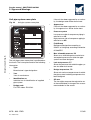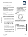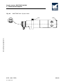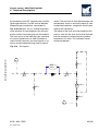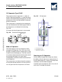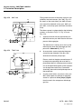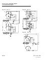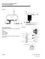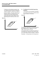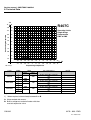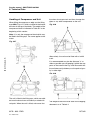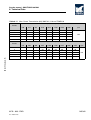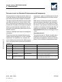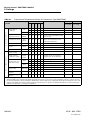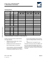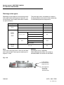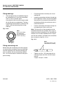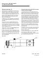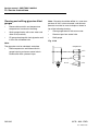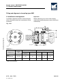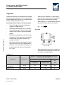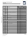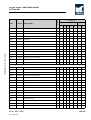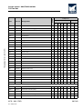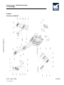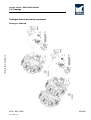
1
Service manual - SMC/TSMC 100 Mk4
Manual for SMC and TSMC Mk4, S-L-E
The SMC/TSMC reciprocating compressor can be
fitted with a range of equipment, depending on the
function and requirements it is expected to meet.
The variants featured on the unit are marked with
an 'x' in the following diagram, with the compressor number stated below.
Some of these variants are discussed in this manual, even if they are not featured on your particular unit.
Compressor type
❑
104 ❑
SMC
TSMC
106
❏
❏
❏
108 ❏
❏ E❏
112 ❏
116 ❏
S
L
Compressor no
01 introduction.fm
Refrigerant
Control
❑
R507 ❑
R717
R22
❑
R134a
Other _________
❏
❑
R404A
❑
UNISAB II control- and regulating system
Analog control system
Compressor
cooling
Thermopump
Water cooled top and side covers
Air cooled top and side covers
Oil cooling
Oil cooling
Drive type
(water-cooled side covers)
OOSI/OOKH
Coupling
V-belts
Explosion-proof electrical design
Equipment for parallel operation
SABROE OVUR oil separator
0178 - 933 - ENG
Rev. 2005.12.09.
1/342
Service manual - SMC/TSMC 100 Mk4
1. Introduction
1. Introduction
The purpose of this manual is to provide the operating personnel with a thorough knowledge of the
compressor as well as information about:
•
The function and maintenance of each
component.
•
Service schedules.
This manual describes the compressor and its
component parts as well as safety instructions/regulations. Moreover, the manual explains
the different settings that can be of assistance to
those who are responsible for the daily operation
and maintenance of the equipment.
To prevent any accidents, assembly and disassembly of components should only be carried out
by authorized personnel.
It is essential that the operating personnel familiarize themselves with the contents of this manual
in order to ensure a proper and efficient operation.
Sabroe Refrigeration (YORK Denmark ApS) hereafter referred to as Sabroe Refrigeration - is
not liable for damage occurring during the warran-
ty period where this is attributable to incorrect operation.
Sabroe Refrigeration's manual concept covers six
standard manuals: Engineering, Operating, Service, Installation and Commissioning, Transport
and Spare Parts. Therefore, references may be
made to chapters which are not part of this manual.
This manual was produced by:
Sabroe Refrigeration (YORK Denmark ApS)
Chr. X’s Vej 201, P.O. Box 1810
8270 Højbjerg, Denmark
Phone +45 87 36 70 00
Fax +45 87 36 70 05
www.sabroe.com
Reg. No 19 05 61 71
Copyright © 2004 Sabroe Refrigeration
This manual must not be copied without the written permission of Sabroe Refrigeration and the
contents must not be imparted to a third party nor
be used for any unauthorised purpose.
Contravention will be prosecuted.
In the space below you may enter the name and address of your local Sabroe Representative
2/342
0178 - 933 - ENG
Rev. 2005.12.09.
Service manual - SMC/TSMC 100 Mk4
0178-933-ENGTOC.fm
Table of Contents
Manual for SMC and TSMC Mk4, S-L-E . . . . . . . . . . . . . . . . . . . . . . . . . . . . . . . . . . . . . . . . . . .
1
Introduction . . . . . . . . . . . . . . . . . . . . . . . . . . . . . . . . . . . . . . . . . . . . . . . . . . . . . . . . . . . . . . . . .
2
Signs and Warnings . . . . . . . . . . . . . . . . . . . . . . . . . . . . . . . . . . . . . . . . . . . . . . . . . . . . . . . . . . .
Identification of Sabroe Refrigeration Equipment . . . . . . . . . . . . . . . . . . . . . . . . . . . . . . . .
Unit pipe system name plate . . . . . . . . . . . . . . . . . . . . . . . . . . . . . . . . . . . . . . . . . . . . . . .
Compressor name plate . . . . . . . . . . . . . . . . . . . . . . . . . . . . . . . . . . . . . . . . . . . . . . . . . . .
Vessel name plate . . . . . . . . . . . . . . . . . . . . . . . . . . . . . . . . . . . . . . . . . . . . . . . . . . . . . . .
Signs in instructions . . . . . . . . . . . . . . . . . . . . . . . . . . . . . . . . . . . . . . . . . . . . . . . . . . . . . .
The sign: CAUTION . . . . . . . . . . . . . . . . . . . . . . . . . . . . . . . . . . . . . . . . . . . . . . . . . . . . . .
The sign: HIGH VOLTAGE . . . . . . . . . . . . . . . . . . . . . . . . . . . . . . . . . . . . . . . . . . . . . . . . .
The sign: The temperature of tangible surfaces . . . . . . . . . . . . . . . . . . . . . . . . . . . . . . . . .
The sign: Internal protection . . . . . . . . . . . . . . . . . . . . . . . . . . . . . . . . . . . . . . . . . . . . . . . .
Other warning signs . . . . . . . . . . . . . . . . . . . . . . . . . . . . . . . . . . . . . . . . . . . . . . . . . . . . . .
Emergency Stop . . . . . . . . . . . . . . . . . . . . . . . . . . . . . . . . . . . . . . . . . . . . . . . . . . . . . . . . .
Safety during Service . . . . . . . . . . . . . . . . . . . . . . . . . . . . . . . . . . . . . . . . . . . . . . . . . . . . .
Warnings in Instructions . . . . . . . . . . . . . . . . . . . . . . . . . . . . . . . . . . . . . . . . . . . . . . . . . . .
Texts Marked with Danger! . . . . . . . . . . . . . . . . . . . . . . . . . . . . . . . . . . . . . . . . . . . . . . . . .
Texts Marked with Warning! . . . . . . . . . . . . . . . . . . . . . . . . . . . . . . . . . . . . . . . . . . . . . . . .
Texts Marked with Caution! . . . . . . . . . . . . . . . . . . . . . . . . . . . . . . . . . . . . . . . . . . . . . . . .
9
10
11
12
13
14
14
14
15
15
15
16
16
17
17
17
17
Safety Precautions . . . . . . . . . . . . . . . . . . . . . . . . . . . . . . . . . . . . . . . . . . . . . . . . . . . . . . . . . . . .
General Safety Instructions and Considerations . . . . . . . . . . . . . . . . . . . . . . . . . . . . . . . .
Personal Safety . . . . . . . . . . . . . . . . . . . . . . . . . . . . . . . . . . . . . . . . . . . . . . . . . . . . . . . . .
Work Area Safety . . . . . . . . . . . . . . . . . . . . . . . . . . . . . . . . . . . . . . . . . . . . . . . . . . . . . . . .
Tool Safety . . . . . . . . . . . . . . . . . . . . . . . . . . . . . . . . . . . . . . . . . . . . . . . . . . . . . . . . . . . . .
Transmission safety . . . . . . . . . . . . . . . . . . . . . . . . . . . . . . . . . . . . . . . . . . . . . . . . . . . . . .
Coupling . . . . . . . . . . . . . . . . . . . . . . . . . . . . . . . . . . . . . . . . . . . . . . . . . . . . . . . . . . . . . . .
Belt drive . . . . . . . . . . . . . . . . . . . . . . . . . . . . . . . . . . . . . . . . . . . . . . . . . . . . . . . . . . . . . . .
Lifting and Carrying Safety . . . . . . . . . . . . . . . . . . . . . . . . . . . . . . . . . . . . . . . . . . . . . . . . .
Installation and Relocation Safety . . . . . . . . . . . . . . . . . . . . . . . . . . . . . . . . . . . . . . . . . . .
Set-Up and Operation Safety . . . . . . . . . . . . . . . . . . . . . . . . . . . . . . . . . . . . . . . . . . . . . . .
Maintenance Safety . . . . . . . . . . . . . . . . . . . . . . . . . . . . . . . . . . . . . . . . . . . . . . . . . . . . . .
Materials Used with this Product . . . . . . . . . . . . . . . . . . . . . . . . . . . . . . . . . . . . . . . . . . . .
First aid for accidents with ammonia . . . . . . . . . . . . . . . . . . . . . . . . . . . . . . . . . . . . . . . . .
General . . . . . . . . . . . . . . . . . . . . . . . . . . . . . . . . . . . . . . . . . . . . . . . . . . . . . . . . . . . . . . . .
Basic rules for first aid . . . . . . . . . . . . . . . . . . . . . . . . . . . . . . . . . . . . . . . . . . . . . . . . . . . .
First aid measures . . . . . . . . . . . . . . . . . . . . . . . . . . . . . . . . . . . . . . . . . . . . . . . . . . . . . . .
First aid for accidents with HFC/HCFC . . . . . . . . . . . . . . . . . . . . . . . . . . . . . . . . . . . . . . . .
General . . . . . . . . . . . . . . . . . . . . . . . . . . . . . . . . . . . . . . . . . . . . . . . . . . . . . . . . . . . . . . . .
Basic rules for first aid . . . . . . . . . . . . . . . . . . . . . . . . . . . . . . . . . . . . . . . . . . . . . . . . . . . .
Protecting the operator as well as the environment . . . . . . . . . . . . . . . . . . . . . . . . . . . . . .
Furthermore, it can be said about refrigerants: . . . . . . . . . . . . . . . . . . . . . . . . . . . . . . . . . .
Purging a refrigeration plant . . . . . . . . . . . . . . . . . . . . . . . . . . . . . . . . . . . . . . . . . . . . . . . .
Cooling media . . . . . . . . . . . . . . . . . . . . . . . . . . . . . . . . . . . . . . . . . . . . . . . . . . . . . . . . . . .
Lubricating oils . . . . . . . . . . . . . . . . . . . . . . . . . . . . . . . . . . . . . . . . . . . . . . . . . . . . . . . . . .
19
19
19
19
20
20
20
20
20
21
21
22
23
24
24
24
24
25
25
25
26
27
28
29
29
0178 - 933 - ENG
Rev. 2005.12.09.
3/342
Service manual - SMC/TSMC 100 Mk4
Cooling water systems . . . . . . . . . . . . . . . . . . . . . . . . . . . . . . . . . . . . . . . . . . . . . . . . . . . . .
29
Technical Description . . . . . . . . . . . . . . . . . . . . . . . . . . . . . . . . . . . . . . . . . . . . . . . . . . . . . . . . . .
Areas of Application of the Reciprocating Compressor Unit . . . . . . . . . . . . . . . . . . . . . . . .
Marine application . . . . . . . . . . . . . . . . . . . . . . . . . . . . . . . . . . . . . . . . . . . . . . . . . . . . . . . .
Description of the Compressors Compressor Types . . . . . . . . . . . . . . . . . . . . . . . . . . . . . .
Compressor Description . . . . . . . . . . . . . . . . . . . . . . . . . . . . . . . . . . . . . . . . . . . . . . . . . . .
Single-stage Compressors . . . . . . . . . . . . . . . . . . . . . . . . . . . . . . . . . . . . . . . . . . . . . . . . . .
Two-stage Compressors Type TSMC 100 . . . . . . . . . . . . . . . . . . . . . . . . . . . . . . . . . . . . . .
Compressor Block . . . . . . . . . . . . . . . . . . . . . . . . . . . . . . . . . . . . . . . . . . . . . . . . . . . . . . . .
Piston Pin Bearing . . . . . . . . . . . . . . . . . . . . . . . . . . . . . . . . . . . . . . . . . . . . . . . . . . . . . . . .
Suction Filters . . . . . . . . . . . . . . . . . . . . . . . . . . . . . . . . . . . . . . . . . . . . . . . . . . . . . . . . . . .
Conversion of TSMC Compressors from Two-stage to Single-stage . . . . . . . . . . . . . . . . .
Oil Separator Type OVUR . . . . . . . . . . . . . . . . . . . . . . . . . . . . . . . . . . . . . . . . . . . . . . . . . .
Mode of Operation . . . . . . . . . . . . . . . . . . . . . . . . . . . . . . . . . . . . . . . . . . . . . . . . . . . . . . . .
Selecting an Oil Separator . . . . . . . . . . . . . . . . . . . . . . . . . . . . . . . . . . . . . . . . . . . . . . . . . .
Oil Return to the Compressor . . . . . . . . . . . . . . . . . . . . . . . . . . . . . . . . . . . . . . . . . . . . . . .
Thermodynamic Liquid Trap (TLT) . . . . . . . . . . . . . . . . . . . . . . . . . . . . . . . . . . . . . . . . . . .
Oil Return in Connection with Parallel Operation . . . . . . . . . . . . . . . . . . . . . . . . . . . . . . . . .
System A . . . . . . . . . . . . . . . . . . . . . . . . . . . . . . . . . . . . . . . . . . . . . . . . . . . . . . . . . . . . . . .
System B . . . . . . . . . . . . . . . . . . . . . . . . . . . . . . . . . . . . . . . . . . . . . . . . . . . . . . . . . . . . . . .
System C . . . . . . . . . . . . . . . . . . . . . . . . . . . . . . . . . . . . . . . . . . . . . . . . . . . . . . . . . . . . . . .
Capacity Regulation of Compressor . . . . . . . . . . . . . . . . . . . . . . . . . . . . . . . . . . . . . . . . . .
Capacity Regulation and Unloading of Compressor . . . . . . . . . . . . . . . . . . . . . . . . . . . . . .
Start Unloading . . . . . . . . . . . . . . . . . . . . . . . . . . . . . . . . . . . . . . . . . . . . . . . . . . . . . . . . . .
Regulating Sequence . . . . . . . . . . . . . . . . . . . . . . . . . . . . . . . . . . . . . . . . . . . . . . . . . . . . . .
Variable speed drive (VSD) . . . . . . . . . . . . . . . . . . . . . . . . . . . . . . . . . . . . . . . . . . . . . . . . .
Compressor Units . . . . . . . . . . . . . . . . . . . . . . . . . . . . . . . . . . . . . . . . . . . . . . . . . . . . . . . .
Instrumentation . . . . . . . . . . . . . . . . . . . . . . . . . . . . . . . . . . . . . . . . . . . . . . . . . . . . . . . . . .
Manometers . . . . . . . . . . . . . . . . . . . . . . . . . . . . . . . . . . . . . . . . . . . . . . . . . . . . . . . . . . . . .
Cooling of the Intermediate Discharge Gas on TSMC Compressors . . . . . . . . . . . . . . . . .
Automatic Regulation of Intermediate Pressure IP . . . . . . . . . . . . . . . . . . . . . . . . . . . . . . .
Determining the Intermediate Pressure IP . . . . . . . . . . . . . . . . . . . . . . . . . . . . . . . . . . . . . .
Cooling Systems for Compressors . . . . . . . . . . . . . . . . . . . . . . . . . . . . . . . . . . . . . . . . . . .
Standard Cooling Systems for Compressors . . . . . . . . . . . . . . . . . . . . . . . . . . . . . . . . . . . .
Description . . . . . . . . . . . . . . . . . . . . . . . . . . . . . . . . . . . . . . . . . . . . . . . . . . . . . . . . . . . . . .
Mounting of Cooling Water Hoses . . . . . . . . . . . . . . . . . . . . . . . . . . . . . . . . . . . . . . . . . . . .
Pressure Loss in the Cooling System in SMC/TSMC Compressors . . . . . . . . . . . . . . . . . .
Description of the Pumping Cycle . . . . . . . . . . . . . . . . . . . . . . . . . . . . . . . . . . . . . . . . . . . .
Ensuring Liquid to the Thermo Pump . . . . . . . . . . . . . . . . . . . . . . . . . . . . . . . . . . . . . . . . .
Power Connection . . . . . . . . . . . . . . . . . . . . . . . . . . . . . . . . . . . . . . . . . . . . . . . . . . . . . . . .
Compressor Accessories . . . . . . . . . . . . . . . . . . . . . . . . . . . . . . . . . . . . . . . . . . . . . . . . . . .
Types of Spare Parts Set: . . . . . . . . . . . . . . . . . . . . . . . . . . . . . . . . . . . . . . . . . . . . . . . . . .
31
31
33
34
36
36
47
47
48
49
50
51
51
51
52
54
56
57
60
62
63
63
65
66
75
76
77
79
82
84
84
86
86
86
88
93
97
99
100
102
103
Technical Data . . . . . . . . . . . . . . . . . . . . . . . . . . . . . . . . . . . . . . . . . . . . . . . . . . . . . . . . . . . . . . .
Technical Data for the SMC 100 Series . . . . . . . . . . . . . . . . . . . . . . . . . . . . . . . . . . . . . . . .
Compressor Capacity . . . . . . . . . . . . . . . . . . . . . . . . . . . . . . . . . . . . . . . . . . . . . . . . . . . . .
Dimension Sketches of Compressor Block . . . . . . . . . . . . . . . . . . . . . . . . . . . . . . . . . . . . .
Planning the Machine Room . . . . . . . . . . . . . . . . . . . . . . . . . . . . . . . . . . . . . . . . . . . . . . . .
105
106
109
109
113
4/342
0178 - 933 - ENG
Rev. 2005.12.09.
0178-933-ENGTOC.fm
Service manual - SMC/TSMC 100 Mk4
Operating Limits Diagrams . . . . . . . . . . . . . . . . . . . . . . . . . . . . . . . . . . . . . . . . . . . . . . . . .
Direction of Rotation of the Compressor . . . . . . . . . . . . . . . . . . . . . . . . . . . . . . . . . . . . . . .
Choice of Electric Motor . . . . . . . . . . . . . . . . . . . . . . . . . . . . . . . . . . . . . . . . . . . . . . . . . . .
Motor Dimension . . . . . . . . . . . . . . . . . . . . . . . . . . . . . . . . . . . . . . . . . . . . . . . . . . . . . . . . .
Starting torque of the compressor . . . . . . . . . . . . . . . . . . . . . . . . . . . . . . . . . . . . . . . . . . .
Moment of Inertia . . . . . . . . . . . . . . . . . . . . . . . . . . . . . . . . . . . . . . . . . . . . . . . . . . . . . . . .
Direction of Rotation of Electric Motor . . . . . . . . . . . . . . . . . . . . . . . . . . . . . . . . . . . . . . . .
Handling of Compressor and Unit . . . . . . . . . . . . . . . . . . . . . . . . . . . . . . . . . . . . . . . . . . . .
Compressor Shaft . . . . . . . . . . . . . . . . . . . . . . . . . . . . . . . . . . . . . . . . . . . . . . . . . . . . . . . .
Coupling . . . . . . . . . . . . . . . . . . . . . . . . . . . . . . . . . . . . . . . . . . . . . . . . . . . . . . . . . . . . . . .
V-belt drive for SMC/TSMC 100 . . . . . . . . . . . . . . . . . . . . . . . . . . . . . . . . . . . . . . . . . . . . .
Transmission Ratio . . . . . . . . . . . . . . . . . . . . . . . . . . . . . . . . . . . . . . . . . . . . . . . . . . . . . . .
Power Transmission . . . . . . . . . . . . . . . . . . . . . . . . . . . . . . . . . . . . . . . . . . . . . . . . . . . . . .
Construction of V-Belt Drive . . . . . . . . . . . . . . . . . . . . . . . . . . . . . . . . . . . . . . . . . . . . . . . .
Service . . . . . . . . . . . . . . . . . . . . . . . . . . . . . . . . . . . . . . . . . . . . . . . . . . . . . . . . . . . . . . . .
Noise from Compressors and Units . . . . . . . . . . . . . . . . . . . . . . . . . . . . . . . . . . . . . . . . . .
Noise Data for Reciprocating Compressors . . . . . . . . . . . . . . . . . . . . . . . . . . . . . . . . . . . .
Reverberation Time . . . . . . . . . . . . . . . . . . . . . . . . . . . . . . . . . . . . . . . . . . . . . . . . . . . . . .
Vibration Data for Compressors - All Compressor Types . . . . . . . . . . . . . . . . . . . . . . . . . .
Specification of Compressor Materials . . . . . . . . . . . . . . . . . . . . . . . . . . . . . . . . . . . . . . . .
Pressure Levels for Standard Compressors and Components . . . . . . . . . . . . . . . . . . . . .
Charging the Compressor with Oil . . . . . . . . . . . . . . . . . . . . . . . . . . . . . . . . . . . . . . . . . . .
Oil Consumption . . . . . . . . . . . . . . . . . . . . . . . . . . . . . . . . . . . . . . . . . . . . . . . . . . . . . . . . .
Selecting Oil Separator . . . . . . . . . . . . . . . . . . . . . . . . . . . . . . . . . . . . . . . . . . . . . . . . . . . .
Selecting Lubricating Oil for SABROE Reciprocating Compressors . . . . . . . . . . . . . . . . .
Data Sheet for Listed Sabroe Oils . . . . . . . . . . . . . . . . . . . . . . . . . . . . . . . . . . . . . . . . . . .
List of Part Numbers for Available Sabroe Oils . . . . . . . . . . . . . . . . . . . . . . . . . . . . . . . . .
List of Major Oil Companies . . . . . . . . . . . . . . . . . . . . . . . . . . . . . . . . . . . . . . . . . . . . . . . .
Selecting Lubricating Oil for SABROE Reciprocating Compressors . . . . . . . . . . . . . . . . .
Oil Changing Intervals . . . . . . . . . . . . . . . . . . . . . . . . . . . . . . . . . . . . . . . . . . . . . . . . . . . .
Data Sheet for Listed Sabroe Oils . . . . . . . . . . . . . . . . . . . . . . . . . . . . . . . . . . . . . . . . . . .
List of Part Numbers for Available Sabroe Oils . . . . . . . . . . . . . . . . . . . . . . . . . . . . . . . . .
List of Major Oil Companies . . . . . . . . . . . . . . . . . . . . . . . . . . . . . . . . . . . . . . . . . . . . . . . .
114
129
130
130
132
135
136
137
138
140
142
142
144
146
147
148
152
153
155
156
157
159
161
161
162
168
169
173
174
179
180
181
194
Settings . . . . . . . . . . . . . . . . . . . . . . . . . . . . . . . . . . . . . . . . . . . . . . . . . . . . . . . . . . . . . . . . . . . .
Safety Precautions . . . . . . . . . . . . . . . . . . . . . . . . . . . . . . . . . . . . . . . . . . . . . . . . . . . . . . .
Qualification Requirements . . . . . . . . . . . . . . . . . . . . . . . . . . . . . . . . . . . . . . . . . . . . . . . . .
Compressor control systems . . . . . . . . . . . . . . . . . . . . . . . . . . . . . . . . . . . . . . . . . . . . . . .
195
195
195
195
Operating instructions . . . . . . . . . . . . . . . . . . . . . . . . . . . . . . . . . . . . . . . . . . . . . . . . . . . . . . . . .
199
Maintenance Instructions . . . . . . . . . . . . . . . . . . . . . . . . . . . . . . . . . . . . . . . . . . . . . . . . . . . . . . .
Safety Precautions . . . . . . . . . . . . . . . . . . . . . . . . . . . . . . . . . . . . . . . . . . . . . . . . . . . . . . .
Safety Measures . . . . . . . . . . . . . . . . . . . . . . . . . . . . . . . . . . . . . . . . . . . . . . . . . . . . . . . . .
Maintenance of the Compressor Unit . . . . . . . . . . . . . . . . . . . . . . . . . . . . . . . . . . . . . . . . .
General . . . . . . . . . . . . . . . . . . . . . . . . . . . . . . . . . . . . . . . . . . . . . . . . . . . . . . . . . . . . . . . .
Service intervals . . . . . . . . . . . . . . . . . . . . . . . . . . . . . . . . . . . . . . . . . . . . . . . . . . . . . . . . .
Measures to be taken . . . . . . . . . . . . . . . . . . . . . . . . . . . . . . . . . . . . . . . . . . . . . . . . . . . . .
Visual Inspection . . . . . . . . . . . . . . . . . . . . . . . . . . . . . . . . . . . . . . . . . . . . . . . . . . . . . . . . .
201
201
201
202
202
203
205
206
0178 - 933 - ENG
Rev. 2005.12.09.
5/342
Service manual - SMC/TSMC 100 Mk4
General Rules for Use of Lubricating Oil in Refrigeration Compressors . . . . . . . . . . . . . . .
Assessing the Oil . . . . . . . . . . . . . . . . . . . . . . . . . . . . . . . . . . . . . . . . . . . . . . . . . . . . . . . . .
Analytical Evaluation . . . . . . . . . . . . . . . . . . . . . . . . . . . . . . . . . . . . . . . . . . . . . . . . . . . . . .
Procedure . . . . . . . . . . . . . . . . . . . . . . . . . . . . . . . . . . . . . . . . . . . . . . . . . . . . . . . . . . . . . .
Analysing the Oil . . . . . . . . . . . . . . . . . . . . . . . . . . . . . . . . . . . . . . . . . . . . . . . . . . . . . . . . .
Limiting Values . . . . . . . . . . . . . . . . . . . . . . . . . . . . . . . . . . . . . . . . . . . . . . . . . . . . . . . . . . .
Charging Compressor with Lubricating Oil . . . . . . . . . . . . . . . . . . . . . . . . . . . . . . . . . . . . .
Searching for Leaks . . . . . . . . . . . . . . . . . . . . . . . . . . . . . . . . . . . . . . . . . . . . . . . . . . . . . . .
Method of Searching for Leaks . . . . . . . . . . . . . . . . . . . . . . . . . . . . . . . . . . . . . . . . . . . . . .
Motor Lubrication . . . . . . . . . . . . . . . . . . . . . . . . . . . . . . . . . . . . . . . . . . . . . . . . . . . . . . . . .
207
208
208
208
208
209
210
211
211
211
Fault-finding Instructions . . . . . . . . . . . . . . . . . . . . . . . . . . . . . . . . . . . . . . . . . . . . . . . . . . . . . . . .
Safety Precautions . . . . . . . . . . . . . . . . . . . . . . . . . . . . . . . . . . . . . . . . . . . . . . . . . . . . . . . .
Qualification Requirements . . . . . . . . . . . . . . . . . . . . . . . . . . . . . . . . . . . . . . . . . . . . . . . . .
How to Carry Out Fault-finding . . . . . . . . . . . . . . . . . . . . . . . . . . . . . . . . . . . . . . . . . . . . . .
Reciprocating Compressor Unit as Part of the Overall System . . . . . . . . . . . . . . . . . . . . . .
Systematic Fault-finding . . . . . . . . . . . . . . . . . . . . . . . . . . . . . . . . . . . . . . . . . . . . . . . . . . . .
Operating Condition . . . . . . . . . . . . . . . . . . . . . . . . . . . . . . . . . . . . . . . . . . . . . . . . . . . . . . .
Using the Troubleshooting Chart . . . . . . . . . . . . . . . . . . . . . . . . . . . . . . . . . . . . . . . . . . . . .
Remedying Malfunctions . . . . . . . . . . . . . . . . . . . . . . . . . . . . . . . . . . . . . . . . . . . . . . . . . . .
213
213
213
214
214
214
214
214
217
Service Instructions . . . . . . . . . . . . . . . . . . . . . . . . . . . . . . . . . . . . . . . . . . . . . . . . . . . . . . . . . . . .
Safety Measures . . . . . . . . . . . . . . . . . . . . . . . . . . . . . . . . . . . . . . . . . . . . . . . . . . . . . . . . .
General Preparations before Service . . . . . . . . . . . . . . . . . . . . . . . . . . . . . . . . . . . . . . . . . .
Ventilation . . . . . . . . . . . . . . . . . . . . . . . . . . . . . . . . . . . . . . . . . . . . . . . . . . . . . . . . . . . . . .
Pressure . . . . . . . . . . . . . . . . . . . . . . . . . . . . . . . . . . . . . . . . . . . . . . . . . . . . . . . . . . . . . . . .
Hot and Cold Surfaces . . . . . . . . . . . . . . . . . . . . . . . . . . . . . . . . . . . . . . . . . . . . . . . . . . . . .
Qualification Requirements . . . . . . . . . . . . . . . . . . . . . . . . . . . . . . . . . . . . . . . . . . . . . . . . .
Main Power Supply . . . . . . . . . . . . . . . . . . . . . . . . . . . . . . . . . . . . . . . . . . . . . . . . . . . . . . .
Tools and Accessories . . . . . . . . . . . . . . . . . . . . . . . . . . . . . . . . . . . . . . . . . . . . . . . . . . . . .
Servicing the piston compressor . . . . . . . . . . . . . . . . . . . . . . . . . . . . . . . . . . . . . . . . . . . . .
Pressure drop test: . . . . . . . . . . . . . . . . . . . . . . . . . . . . . . . . . . . . . . . . . . . . . . . . . . . . . . . .
Removing refrigerant from compressor . . . . . . . . . . . . . . . . . . . . . . . . . . . . . . . . . . . . . . . .
Servicing the refrigeration plant . . . . . . . . . . . . . . . . . . . . . . . . . . . . . . . . . . . . . . . . . . . . . .
Maintenance of reciprocating compressor . . . . . . . . . . . . . . . . . . . . . . . . . . . . . . . . . . . . . .
General . . . . . . . . . . . . . . . . . . . . . . . . . . . . . . . . . . . . . . . . . . . . . . . . . . . . . . . . . . . . . . . .
Preparation for maintenance . . . . . . . . . . . . . . . . . . . . . . . . . . . . . . . . . . . . . . . . . . . . . . . .
Pump-down . . . . . . . . . . . . . . . . . . . . . . . . . . . . . . . . . . . . . . . . . . . . . . . . . . . . . . . . . . . . .
1. If the compressor is operational . . . . . . . . . . . . . . . . . . . . . . . . . . . . . . . . . . . . . . . . . . . .
2. If the compressor is inoperative . . . . . . . . . . . . . . . . . . . . . . . . . . . . . . . . . . . . . . . . . . . .
Dismantling and assembly . . . . . . . . . . . . . . . . . . . . . . . . . . . . . . . . . . . . . . . . . . . . . . . . . .
Water covers . . . . . . . . . . . . . . . . . . . . . . . . . . . . . . . . . . . . . . . . . . . . . . . . . . . . . . . . . . . .
Fitting water covers . . . . . . . . . . . . . . . . . . . . . . . . . . . . . . . . . . . . . . . . . . . . . . . . . . . . . . .
Top covers . . . . . . . . . . . . . . . . . . . . . . . . . . . . . . . . . . . . . . . . . . . . . . . . . . . . . . . . . . . . . .
Fitting top cover . . . . . . . . . . . . . . . . . . . . . . . . . . . . . . . . . . . . . . . . . . . . . . . . . . . . . . . . . .
Mounting top and water covers . . . . . . . . . . . . . . . . . . . . . . . . . . . . . . . . . . . . . . . . . . . . . .
Discharge valve . . . . . . . . . . . . . . . . . . . . . . . . . . . . . . . . . . . . . . . . . . . . . . . . . . . . . . . . . .
Pos. 20 . . . . . . . . . . . . . . . . . . . . . . . . . . . . . . . . . . . . . . . . . . . . . . . . . . . . . . . . . . . . . . . . .
Discharge valve types: . . . . . . . . . . . . . . . . . . . . . . . . . . . . . . . . . . . . . . . . . . . . . . . . . . . . .
227
227
228
228
228
228
228
228
228
229
229
230
231
233
233
233
233
233
233
234
234
234
234
235
236
237
237
238
6/342
0178 - 933 - ENG
Rev. 2005.12.09.
0178-933-ENGTOC.fm
Service manual - SMC/TSMC 100 Mk4
Dismantling . . . . . . . . . . . . . . . . . . . . . . . . . . . . . . . . . . . . . . . . . . . . . . . . . . . . . . . . . . . . .
Assembly . . . . . . . . . . . . . . . . . . . . . . . . . . . . . . . . . . . . . . . . . . . . . . . . . . . . . . . . . . . . . .
Tightness testing of discharge valve . . . . . . . . . . . . . . . . . . . . . . . . . . . . . . . . . . . . . . . . . .
Service life of discharge and suction valves . . . . . . . . . . . . . . . . . . . . . . . . . . . . . . . . . . . .
Cylinder lining with suction valve . . . . . . . . . . . . . . . . . . . . . . . . . . . . . . . . . . . . . . . . . . . .
Extracting cylinder lining . . . . . . . . . . . . . . . . . . . . . . . . . . . . . . . . . . . . . . . . . . . . . . . . . . .
Dismantling suction valve . . . . . . . . . . . . . . . . . . . . . . . . . . . . . . . . . . . . . . . . . . . . . . . . . .
Mounting suction valve . . . . . . . . . . . . . . . . . . . . . . . . . . . . . . . . . . . . . . . . . . . . . . . . . . . .
Inserting cylinder lining . . . . . . . . . . . . . . . . . . . . . . . . . . . . . . . . . . . . . . . . . . . . . . . . . . . .
Connecting rod . . . . . . . . . . . . . . . . . . . . . . . . . . . . . . . . . . . . . . . . . . . . . . . . . . . . . . . . . .
Procedure for removing piston and connecting rod . . . . . . . . . . . . . . . . . . . . . . . . . . . . . .
Fitting bearings . . . . . . . . . . . . . . . . . . . . . . . . . . . . . . . . . . . . . . . . . . . . . . . . . . . . . . . . . .
Fitting connecting rod . . . . . . . . . . . . . . . . . . . . . . . . . . . . . . . . . . . . . . . . . . . . . . . . . . . . .
Piston . . . . . . . . . . . . . . . . . . . . . . . . . . . . . . . . . . . . . . . . . . . . . . . . . . . . . . . . . . . . . . . . .
Fitting piston rings in piston . . . . . . . . . . . . . . . . . . . . . . . . . . . . . . . . . . . . . . . . . . . . . . . .
Assembling and stripping down piston and connecting rod . . . . . . . . . . . . . . . . . . . . . . . .
Shaft seal . . . . . . . . . . . . . . . . . . . . . . . . . . . . . . . . . . . . . . . . . . . . . . . . . . . . . . . . . . . . . .
Assembling and mounting shaft seal . . . . . . . . . . . . . . . . . . . . . . . . . . . . . . . . . . . . . . . . .
Crankshaft . . . . . . . . . . . . . . . . . . . . . . . . . . . . . . . . . . . . . . . . . . . . . . . . . . . . . . . . . . . . .
Dismantling crankshaft . . . . . . . . . . . . . . . . . . . . . . . . . . . . . . . . . . . . . . . . . . . . . . . . . . . .
Inspection . . . . . . . . . . . . . . . . . . . . . . . . . . . . . . . . . . . . . . . . . . . . . . . . . . . . . . . . . . . . . .
Refitting crankshaft . . . . . . . . . . . . . . . . . . . . . . . . . . . . . . . . . . . . . . . . . . . . . . . . . . . . . . .
Main bearings . . . . . . . . . . . . . . . . . . . . . . . . . . . . . . . . . . . . . . . . . . . . . . . . . . . . . . . . . . .
Compressor lubricating system . . . . . . . . . . . . . . . . . . . . . . . . . . . . . . . . . . . . . . . . . . . . .
Oil pump . . . . . . . . . . . . . . . . . . . . . . . . . . . . . . . . . . . . . . . . . . . . . . . . . . . . . . . . . . . . . . .
Dismantling of oil pump . . . . . . . . . . . . . . . . . . . . . . . . . . . . . . . . . . . . . . . . . . . . . . . . . . .
Oil pressure valve . . . . . . . . . . . . . . . . . . . . . . . . . . . . . . . . . . . . . . . . . . . . . . . . . . . . . . . .
Adjustment . . . . . . . . . . . . . . . . . . . . . . . . . . . . . . . . . . . . . . . . . . . . . . . . . . . . . . . . . . . . .
Service . . . . . . . . . . . . . . . . . . . . . . . . . . . . . . . . . . . . . . . . . . . . . . . . . . . . . . . . . . . . . . . .
By-pass valve pos. 24 . . . . . . . . . . . . . . . . . . . . . . . . . . . . . . . . . . . . . . . . . . . . . . . . . . . . .
Strainer . . . . . . . . . . . . . . . . . . . . . . . . . . . . . . . . . . . . . . . . . . . . . . . . . . . . . . . . . . . . . . . .
Oil filter . . . . . . . . . . . . . . . . . . . . . . . . . . . . . . . . . . . . . . . . . . . . . . . . . . . . . . . . . . . . . . . .
Suction filters . . . . . . . . . . . . . . . . . . . . . . . . . . . . . . . . . . . . . . . . . . . . . . . . . . . . . . . . . . .
Monitoring cylinder lining insertion . . . . . . . . . . . . . . . . . . . . . . . . . . . . . . . . . . . . . . . . . . .
1. Checking clearance volume . . . . . . . . . . . . . . . . . . . . . . . . . . . . . . . . . . . . . . . . . . . . . .
Adjustment is carried out as follows: . . . . . . . . . . . . . . . . . . . . . . . . . . . . . . . . . . . . . . . . .
2. Checking lifting reserve . . . . . . . . . . . . . . . . . . . . . . . . . . . . . . . . . . . . . . . . . . . . . . . . .
Pressure gauges . . . . . . . . . . . . . . . . . . . . . . . . . . . . . . . . . . . . . . . . . . . . . . . . . . . . . . . . .
Adjustment to other temperature ranges . . . . . . . . . . . . . . . . . . . . . . . . . . . . . . . . . . . . . .
Cleaning and refilling glycerine-filled gauges . . . . . . . . . . . . . . . . . . . . . . . . . . . . . . . . . . .
Fitting and alignment of coupling type AMR . . . . . . . . . . . . . . . . . . . . . . . . . . . . . . . . . . .
4. Installation and alignment . . . . . . . . . . . . . . . . . . . . . . . . . . . . . . . . . . . . . . . . . . . . . . . .
Preliminary installation . . . . . . . . . . . . . . . . . . . . . . . . . . . . . . . . . . . . . . . . . . . . . . . . . . . .
Alignment . . . . . . . . . . . . . . . . . . . . . . . . . . . . . . . . . . . . . . . . . . . . . . . . . . . . . . . . . . . . . .
Achieving correct centre height . . . . . . . . . . . . . . . . . . . . . . . . . . . . . . . . . . . . . . . . . . . . .
Achieving parallel shafts in vertical plane . . . . . . . . . . . . . . . . . . . . . . . . . . . . . . . . . . . . . .
Final installation . . . . . . . . . . . . . . . . . . . . . . . . . . . . . . . . . . . . . . . . . . . . . . . . . . . . . . . . .
Refrigeration plant maintenance . . . . . . . . . . . . . . . . . . . . . . . . . . . . . . . . . . . . . . . . . . . . .
Operational reliability . . . . . . . . . . . . . . . . . . . . . . . . . . . . . . . . . . . . . . . . . . . . . . . . . . . . .
0178 - 933 - ENG
Rev. 2005.12.09.
239
239
239
239
240
240
240
240
240
241
241
242
242
243
243
243
244
247
248
248
249
249
249
251
252
252
253
253
253
254
255
255
257
258
258
258
259
261
261
262
263
263
264
265
266
266
266
267
267
7/342
Service manual - SMC/TSMC 100 Mk4
Pumping down the refrigeration plant . . . . . . . . . . . . . . . . . . . . . . . . . . . . . . . . . . . . . . . . .
Dismantling plant . . . . . . . . . . . . . . . . . . . . . . . . . . . . . . . . . . . . . . . . . . . . . . . . . . . . . . . . .
Tightness testing and pump-down of refrigeration plant . . . . . . . . . . . . . . . . . . . . . . . . . . .
Torques etc. . . . . . . . . . . . . . . . . . . . . . . . . . . . . . . . . . . . . . . . . . . . . . . . . . . . . . . . . . . . . .
Ordering spare parts . . . . . . . . . . . . . . . . . . . . . . . . . . . . . . . . . . . . . . . . . . . . . . . . . . . . . .
267
267
268
268
269
Part list . . . . . . . . . . . . . . . . . . . . . . . . . . . . . . . . . . . . . . . . . . . . . . . . . . . . . . . . . . . . . . . . . . . . .
How to use the part list . . . . . . . . . . . . . . . . . . . . . . . . . . . . . . . . . . . . . . . . . . . . . . . . . . . .
Parts list - 0662-022 . . . . . . . . . . . . . . . . . . . . . . . . . . . . . . . . . . . . . . . . . . . . . . . . . . . . . . .
Tools for compressor . . . . . . . . . . . . . . . . . . . . . . . . . . . . . . . . . . . . . . . . . . . . . . . . . . . . . .
Tools for compressor . . . . . . . . . . . . . . . . . . . . . . . . . . . . . . . . . . . . . . . . . . . . . . . . . . . . . .
SMC 104-116 Mk3 & TSMC 108-116 Mk3 - Type S-L-E . . . . . . . . . . . . . . . . . . . . . . . . . .
Supplementary tool set for SMC 100 Mk4 . . . . . . . . . . . . . . . . . . . . . . . . . . . . . . . . . . . . . .
271
271
272
304
305
305
307
Drawings . . . . . . . . . . . . . . . . . . . . . . . . . . . . . . . . . . . . . . . . . . . . . . . . . . . . . . . . . . . . . . . . . . . .
SMC 104-106-108 . . . . . . . . . . . . . . . . . . . . . . . . . . . . . . . . . . . . . . . . . . . . . . . . . . . . . . . .
TSMC 108 . . . . . . . . . . . . . . . . . . . . . . . . . . . . . . . . . . . . . . . . . . . . . . . . . . . . . . . . . . . . . .
SMC 112-116 . . . . . . . . . . . . . . . . . . . . . . . . . . . . . . . . . . . . . . . . . . . . . . . . . . . . . . . . . . . .
TSMC 116 . . . . . . . . . . . . . . . . . . . . . . . . . . . . . . . . . . . . . . . . . . . . . . . . . . . . . . . . . . . . . .
Piston, cylinder liner and connecting rod . . . . . . . . . . . . . . . . . . . . . . . . . . . . . . . . . . . . . . .
Shaft seal . . . . . . . . . . . . . . . . . . . . . . . . . . . . . . . . . . . . . . . . . . . . . . . . . . . . . . . . . . . . . . .
Covers . . . . . . . . . . . . . . . . . . . . . . . . . . . . . . . . . . . . . . . . . . . . . . . . . . . . . . . . . . . . . . . . .
Crankshaft, bearings and coupling . . . . . . . . . . . . . . . . . . . . . . . . . . . . . . . . . . . . . . . . . . .
Oil system . . . . . . . . . . . . . . . . . . . . . . . . . . . . . . . . . . . . . . . . . . . . . . . . . . . . . . . . . . . . . .
Unloading frame/cylinder . . . . . . . . . . . . . . . . . . . . . . . . . . . . . . . . . . . . . . . . . . . . . . . . . . .
By-pass and service valves . . . . . . . . . . . . . . . . . . . . . . . . . . . . . . . . . . . . . . . . . . . . . . . . .
Stop valves . . . . . . . . . . . . . . . . . . . . . . . . . . . . . . . . . . . . . . . . . . . . . . . . . . . . . . . . . . . . .
Suction filters . . . . . . . . . . . . . . . . . . . . . . . . . . . . . . . . . . . . . . . . . . . . . . . . . . . . . . . . . . . .
Thermo pump cover . . . . . . . . . . . . . . . . . . . . . . . . . . . . . . . . . . . . . . . . . . . . . . . . . . . . . . .
Analogue control and safety equipment . . . . . . . . . . . . . . . . . . . . . . . . . . . . . . . . . . . . . . . .
309
309
310
311
312
313
314
315
316
317
318
319
320
321
322
323
Final Disposal . . . . . . . . . . . . . . . . . . . . . . . . . . . . . . . . . . . . . . . . . . . . . . . . . . . . . . . . . . . . . . . .
General . . . . . . . . . . . . . . . . . . . . . . . . . . . . . . . . . . . . . . . . . . . . . . . . . . . . . . . . . . . . . . . .
Safety Precautions . . . . . . . . . . . . . . . . . . . . . . . . . . . . . . . . . . . . . . . . . . . . . . . . . . . . . . . .
Disposal of Machine Parts . . . . . . . . . . . . . . . . . . . . . . . . . . . . . . . . . . . . . . . . . . . . . . . . . .
Disposal of Oil and Refrigerant . . . . . . . . . . . . . . . . . . . . . . . . . . . . . . . . . . . . . . . . . . . . . .
Disposal of Electrical Components . . . . . . . . . . . . . . . . . . . . . . . . . . . . . . . . . . . . . . . . . . .
Disposal of Batteries . . . . . . . . . . . . . . . . . . . . . . . . . . . . . . . . . . . . . . . . . . . . . . . . . . . . . .
325
325
325
325
325
326
326
Appendices . . . . . . . . . . . . . . . . . . . . . . . . . . . . . . . . . . . . . . . . . . . . . . . . . . . . . . . . . . . . . . . . . .
References to Instructions . . . . . . . . . . . . . . . . . . . . . . . . . . . . . . . . . . . . . . . . . . . . . . . . . .
Appendix . . . . . . . . . . . . . . . . . . . . . . . . . . . . . . . . . . . . . . . . . . . . . . . . . . . . . . . . . . . . . . .
Torque Moments for Screws and Bolts . . . . . . . . . . . . . . . . . . . . . . . . . . . . . . . . . . . . . . . .
Coupling data . . . . . . . . . . . . . . . . . . . . . . . . . . . . . . . . . . . . . . . . . . . . . . . . . . . . . . . . . . . .
Sundry Clearances and Check Dimensions . . . . . . . . . . . . . . . . . . . . . . . . . . . . . . . . . . . .
327
327
327
328
330
331
Index . . . . . . . . . . . . . . . . . . . . . . . . . . . . . . . . . . . . . . . . . . . . . . . . . . . . . . . . . . . . . . . . . . . . . . .
333
8/342
0178 - 933 - ENG
Rev. 2005.12.09.
Service manual - SMC/TSMC 100 Mk4
2. Signs and Warnings
2. Signs and Warnings
The purpose of this chapter is to describe:
•
How Sabroe Refrigeration equipment can
be identified.
•
All warning signs used on equipment delivered by Sabroe Refrigeration.
•
How information important to the safety of
personnel and equipment is presented in instructions belonging to equipment delivered
by Sabroe Refrigeration.
This chapter is intended for all user categories.
WDanger!
Risk of injury to personnel and damage to equipment! Always read the safety precautions belonging to this equipment before starting the installation process. Failure to comply with safety
precautions may cause death or injury to personnel. It may also cause damage to or destruction of
the equipment.
02 signs and warnings.fm
This chapter describes the importance of the individual signs which are attached to the
Sabroe Refrigeration products.
Before a compressor/unit is put into operation it
must be provided with the warning signs corresponding to the actual type of compressor/unit in
accordance with the rules and regulations in force.
0178 - 933 - ENG
Rev. 2005.12.09.
9/342
Service manual - SMC/TSMC 100 Mk4
2. Signs and Warnings
Identification of Sabroe Refrigeration Equipment
All Sabroe Refrigeration equipment can be identified by one or several name plates placed as illustrated
by the following drawing:
Fig. 2.1
2
1
3
1. Compressor name plate
2. Vessel name plate
3. Unit pipe system name plate
10/342
0178 - 933 - ENG
Rev. 2005.12.09.
Service manual - SMC/TSMC 100 Mk4
2. Signs and Warnings
Unit pipe system name plate
02 signs and warnings.fm
Fig. 2.2
Unit pipe system name plate
The unit pipe system name plate is positioned on
the frame. The name plate contains the following
information:
•
If the unit has been approved by an authority, the design code will be shown here.
Type
Manufacturer's type designation.
•
Year
Year of manufacture.
•
Identification no.
Individual no. for identification of supplied
pipe system.
•
Design code
For PED orders: EN 378-2
0178 - 933 - ENG
Rev. 2005.12.09.
•
Approval no.
If the unit has been approved by an authority, the approval no. will be shown here.
•
Pressure system
Low pressure side of compressor piping is
referred to as LP.
High pressure side of compressor piping is
referred to as HP.
•
Fluid/Group
Refrigerant designation according to
ISO817 or fluid group according to directive
67/548/EEC.
•
Max. allowable pressure, PS
Shows max allowable pressure relative to
atmospheric pressure for which the pipe
system has been designed.
•
Leak test pressure, PT
Shows the pressure with which the pipe system has been leak tested.
•
Design temperature, TS
Shows min and max temperatures for which
the pipe system including components has
been designed.
•
CE xxxx
The four digits compose the registration no.
of the notified body in charge of the assessment modules for the vessel.
11/342
Service manual - SMC/TSMC 100 Mk4
2. Signs and Warnings
Compressor name plate
Fig. 2.3
Year
Year of manufacture.
•
Type
Manufacturer's type designation.
•
Nominal speed
Shows rotational speed of drive shaft at typical running condition.
•
Swept volume
Shows swept volume of compressor in m3/h
at nominal speed.
•
Max allowable pressure, Ps
Shows max. working pressure of compressor.
•
Max allowable pressure, Pss
Shows max allowable pressure at compressor standstill.
Compressor name plate
The compressor name plate is positioned on the
compressor. The plate contains the following information:
•
•
Compressor no.
Compressor manufacturing number.
12/342
0178 - 933 - ENG
Rev. 2005.12.09.
Service manual - SMC/TSMC 100 Mk4
2. Signs and Warnings
Vessel name plate
02 signs and warnings.fm
Fig. 2.4
Design code
Shows the design code according to which
the vessel was manufactured.
•
Approval no./CAT
Shows the approval no. of the vessel issued
by the relevant authority as well as the category according to PED 97/23/EEC,
Article 9.
•
Side
Refers to the columns “Shell” and “Tube”.
•
Fluid
Shows the refrigerant designation according to ISO817.
•
Allowable pressure, PS
Shows min and max pressure relative to atmospheric pressure for which the vessel or
vessel part has been designed.
•
Allowable temperature, TS
Shows min and max temperatures for which
the vessel has been designed.
•
Volume
Shows volume of the vessel in litres.
•
CE xxxx
The four digits compose the registration no.
of the notified body in charge of the assessment modules for the vessel.
Vessel name plate
/
/
/
/
The vessel name plate is positioned on the shell
of the vessel. The name plate contains the following information:
•
•
Vessel no.
Vessel number stated by
Sabroe Refrigeration.
•
Year
Year of manufacture.
•
Type
Manufacturer's type designation.
0178 - 933 - ENG
Rev. 2005.12.09.
13/342
Service manual - SMC/TSMC 100 Mk4
2. Signs and Warnings
In the following section, all signs which may
be found on the equipment are described. The
number of signs, however, may vary from
product to product.
Signs in instructions
The sign: CAUTION
A CAUTION tag like the one illustrated below is
fixed to the compressor. The sign imposes the users to read the Safety precautions chapter in the
manual before handling, operating, or servicing
the compressor and unit.
Caution
The sign: HIGH VOLTAGE
WDanger
HIGH VOLTAGE!
Before working on any electrical circuits, turn the
main switch “OFF” and lock it. Dismantle the main
fuses to the compressor unit.
Unless expressly stated in applicable
Sabroe Refrigeration documentation or by a
Sabroe Refrigeration field service representative,
do NOT work with the electrical power “ON”. Any
work with the electrical power “ON” should be performed by a Sabroe Refrigeration field service
representative. The customer and subsequent
transferees must make sure that any other person
performing work with the electrical power “ON” is
trained and technically qualified.
Before handling, installing, operating, or
servicing the compressor and unit, read
the Safety precautions chapter in the
Operating manual.
It is the responsibility of the operator or
his employer that the Operating manual
is always available.
This sign must not be removed nor be
damaged in any way.
Antes de manejer, instalar, poner en marcha o dar servicio al compresor y la unidad, leer la sección Precauciones de
seguridad en el Libro de Instrucciones.
Es respondabilidad del operarío o de su
patrón, que el libro de instrucciones
permanezca siempre al alcance de la
mano.
Esta señal no debe de ninguna manera
2516-297
suprimirse o dañarse.
14/342
0178 - 933 - ENG
Rev. 2005.12.09.
Service manual - SMC/TSMC 100 Mk4
2. Signs and Warnings
The sign: The temperature of tangible
surfaces
When a compressor is working, the surfaces
which are in contact with the warm discharge gas
will also get warm. However, the temperature depends on the refrigerants used as well as the operating conditions of the compressor. Often the
temperature exceeds 70°C [158°F], which for
metal surfaces may cause skin burns even at a
light touch.
02 signs and warnings.fm
Consequently, the compressors are equipped
with yellow warning signs signalling that pipes,
vessels, and machine parts will become so hot
during operation that your skin will get burnt if you
touch them for one second or more.
Other warning signs
Hazardous substance!
Dangerous noise level,
use hearing protectors!
Internal overpressure!
Cold surfaces!
The sign: Internal protection
Compressor blocks and units are usually delivered without any refrigerant or oil.
To protect the compressors against internal corrosion, they are delivered evacuated of all atmospheric air and charged with Nitrogen (N2) to an
overpressure of 0.2 bar [3 psi].
In such cases a yellow sign is affixed to a visible
spot on the compressor.
Påfyldt beskyttelsesgas
Charged with inert gas
Enthält Schutzgas
Chargé du gaz protecteur
Contiene gas protector
0178 - 933 - ENG
Rev. 2005.12.09.
N2
0,2 bar
3 PSI
1534-169
15/342
Service manual - SMC/TSMC 100 Mk4
2. Signs and Warnings
Emergency Stop
Fig. 2.5
•
Switch off all electric components on the
compressor/unit before the dismantling/servicing.
•
Make sure that there is neither overpressure
nor any refrigerant in the part to be dismantled. Close all necessary stop valves.
•
Use gloves and safety goggles and make
sure to have a gas mask ready for use.
•
Use the prescribed tools and check that
they are properly maintained and in good
working condition. In explosion-proof areas,
use tools especially suited for this specific
purpose.
•
When dismantling the top covers, attention
should be paid to the considerable spring
force beneath the covers. When the screws
are loosened, the cover must lift itself from
the frame as described in the instruction
manual.
Emergency stop on the reciprocating
compressor unit
Electromechanical control system
Emergency stop, mounted when
installing the unit
UNISAB II control system
Emergency stop
Fig. 2.6
Springs
Top cover
Safety during Service
Before dismantling or servicing a compressor or
unit attention should be paid to the following
points:
•
Read the Safety Precautions in chapter 3
before opening the compressor and other
parts of the refrigeration plant.
•
Make sure that the motor cannot start up inadvertently. It is recommended to remove
all main fuses.
16/342
•
Before dismantling the side covers, empty
the crankcase of its oil content.
•
Check that the heating rod in the crankcase
is de-energized.
0178 - 933 - ENG
Rev. 2005.12.09.
Service manual - SMC/TSMC 100 Mk4
2. Signs and Warnings
Warnings in Instructions
This section describes warnings used in instructions pertaining to Sabroe Refrigeration equipment.
Information of importance to the safety of personnel or equipment is given at three levels.
•
Danger!
•
Warning!
•
Caution!
02 signs and warnings.fm
There is an important distinction between these
three levels. However, as shown below, the principle is the same at all three levels.
Failure to observe information marked with Danger! may cause death or serious injury to personnel or even to a third party.
Texts Marked with Warning!
The example below shows how information of importance to the safety of involved personnel or of
major importance to the safety of equipment is
presented.
WWarning!
Risk of damage to compressor! Always consult
your supplier before using a compressor under
operating conditions outside the specified working
range.
Note: Information is sometimes given in a Note.
A Note is used to emphasise information but it is
never used for information vital to the safety of
personnel and equipment.
Texts Marked with Caution!
Texts Marked with Danger!
The example below shows how information of importance to the safety of equipment is presented.
The example below shows how information vital to
the safety of involved personnel is presented.
WCaution!
WDanger!
Risk of electrical shock! Always turn off the main
switch before servicing the unit! Contact with high
voltage may cause death or serious injury.
0178 - 933 - ENG
Rev. 2005.12.09.
Risk of incorrect viscosity! Always make sure that
all oils used are mixable without causing chemical
reactions. Chemical reactions might have serious
effects on the viscosity.
Failure to observe information marked with Caution! may cause damage to equipment.
17/342
Service manual - SMC/TSMC 100 Mk4
2. Signs and Warnings
18/342
0178 - 933 - ENG
Rev. 2005.12.09.
Service manual - SMC/TSMC 100 Mk4
3. Safety Precautions
3. Safety Precautions
The purpose of this chapter is to provide general
safety precautions for this equipment. Additional
safety precautions relating to a specific task are
given in the corresponding documents.
The safety precautions are intended for all user
categories.
W Danger!
03 safety precautions.fm
Risk of injury to personnel and damage to equipment! Always read the safety precautions belonging to this equipment before start. Failure to comply with safety precautions may cause death or injury to personnel. It may also cause damage to or
destruction of the equipment.
W Warning!
Read related safety precautions before operating
the compressor/unit. Failure to follow safety instructions may result in serious personal injury or
death.
Important!
The safety precautions for this
Sabroe Refrigeration compressor have been prepared to assist the operator, programmer and
maintenance personnel in practicing good shop
safety procedures.
Operator and maintenance personnel must read
and understand these precautions completely before operating, setting up, running or performing
maintenance on the compressor/unit.
These precautions are to be used as a supplement to the safety precautions and warnings included in:
a.
b.
All other manuals pertaining to the compressor/unit.
Local, plant and shop safety rules and codes.
0178 - 933 - ENG
Rev. 2005.12.09.
c.
National safety rules, regulations and directives.
General Safety Instructions and
Considerations
Personal Safety
Owners, operators, set-up, maintenance and
service personnel must be aware that constant
day-to-day safety procedures are a vital part of
their job. Accident prevention must be one of the
principal objectives of the job, regardless of the
activity involved.
Know and respect the compressor/unit. Read and
carry out the prescribed safety and checking procedures.
Make sure that everyone who works for, with or
near you fully understands and - more importantly
- complies with the following safety precautions
and procedures when operating this compressor/unit.
Observe the safety warnings on the compressor/unit.
Use safety equipment. Wear approved eye or face
protection as well as gloves when working with
parts containing refrigerant and/or lubricating oil.
Safety shoes with slip-proof soles can help you
avoid injuries. Keep your safety equipment in
good condition.
Never operate or service this equipment if affected by alcohol, drugs or other substances or if in a
condition which decreases alertness or judgment.
Work Area Safety
Always keep your work area clean. Dirty work areas with such hazards as oil, debris or water on
the floor may cause someone to fall onto the floor,
19/342
Service manual - SMC/TSMC 100 Mk4
3. Safety Precautions
into the machine or onto other objects resulting in
serious personal injury.
sure that the compressor motor cannot start up
unintended.
Make sure your work area is free of hazardous obstructions and be aware of protruding machine
parts.
When performing service where the motor is dismantled from the base frame, follow the instructions for coupling alignment in the Installations Instructions section.
Always keep your work area tidy so that you can
escape if a dangerous situation should arise.
Report unsafe working conditions to your supervisor or safety department.
Tool Safety
Always make sure that the hand tools are in proper working condition.
Remove hand tools such as wrenches, measuring
equipment, hammers, etc. from the compressor/unit immediately after use.
Transmission safety
Coupling
The coupling guard for directly driven compressors is not designed to resist unintended load.
Therefore, do not step on it or load it in any way
during operation. The guard is marked with a sign.
W
When mounting the coupling guard make sure
that it is not in contact with any rotating parts. For
correct torque see the Service Instructions section. After 20 hours check to see if tightening-up is
required. Check the coupling guard for correct
tightening, cracks or other defects every 5000
hours.
W
Do not start the compressor until the coupling
guard or belt drive is mounted correctly. Before
performing any kind of work on the coupling, make
20/342
Belt drive
The belt guard is not designed to resist unintended load and is therefore marked with a warning
sign - “No step”. When the belt guard is mounted
it should be checked after 20 hours whether tightening-up is required. Check the belt guard for correct tightening, cracks or other defects every 5000
hours.
Lifting and Carrying Safety
Contact Sabroe Refrigeration if you have any
questions or if you are not sure about the proper
procedures for lifting and carrying.
Before lifting or carrying a compressor/unit or other parts, determine the weight and size by means
of e.g. tags, shipping data, labels, marked information or manuals.
Use power hoists or other mechanical lifting and
carrying equipment for heavy, bulky or unwieldy
objects. Use hook-up methods recommended by
your safety department and familiarise yourself
with the signals for safely directing a crane operator.
Never place any part of your body under a suspended load or move a suspended load over any
other persons. Before lifting, be certain that you
have a safe spot for depositing the load. Never
work on a component while it is hanging from a
crane or any other lifting mechanism.
If in doubt as to the size or type of lifting equipment, the method and procedures to be used in
connection with lifting, contact
0178 - 933 - ENG
Rev. 2005.12.09.
Service manual - SMC/TSMC 100 Mk4
3. Safety Precautions
Sabroe Refrigeration before proceeding to lift the
compressor, motor, unit or its components.
the O position after the power source connection is complete.
Always inspect slings, chains, hoists and other lifting devices prior to use. Do not use lifting devices
which are defective or in a questionable condition.
Before starting the compressor for the first time,
make sure that all the motors rotate in the indicated direction.
Never exceed the lifting capacity of cranes, slings,
eyebolts and other lifting equipment. Follow
standards and instructions applicable to any lifting
equipment used.
03 safety precautions.fm
Before inserting an eyebolt, be certain that both
the eyebolt and the hole have the same size and
type of threads. To attain safe working loads, at
least 90% of the threaded portion of a standard
forged eyebolt must be engaged.
W Warning!
Failure to follow safety instructions on this page
may result in serious personal injury or death.
Installation and Relocation Safety
Before lifting the compressor, unit or other parts of
the plant, consult the Engineering manual or
Sabroe Refrigeration for proper methods and procedures.
An electrician must read and understand the electrical diagrams prior to connecting the machine to
the power source. After connecting the machine,
test all aspects of the electrical system for proper
functioning. Always make sure that the machine is
grounded properly. Place all selector switches in
their O or neutral (disengaged) position. The
doors of the main electrical cabinet must be
closed and the main disconnect switch must be in
0178 - 933 - ENG
Rev. 2005.12.09.
Set-Up and Operation Safety
Read and understand all the safety instructions
before setting up, operating or servicing this compressor. Assign only qualified personnel instructed in safety and all machine functions to operate
or service this compressor.
Operators and maintenance personnel must carefully read, understand and fully comply with all
warnings and instruction plates mounted on the
machine. Do not paint over, alter or deface these
plates or remove them from the compressor/unit.
Replace all plates which become illegible. Replacement plates can be purchased from
Sabroe Refrigeration.
Safety guards, shields, barriers, covers and protective devices must not be removed while the
compressor/unit is operating.
All safety features, disengagements and interlocks must be in place and function correctly before this equipment is put in operation. Never bypass or wire around any safety device.
Keep all parts of your body off the compressor/motor/unit during operation. Never lean on or
reach over the compressor.
During operation, pay attention to the compressor
unit process. Excessive vibration, unusual
sounds, etc. can indicate problems requiring your
immediate attention.
21/342
Service manual - SMC/TSMC 100 Mk4
3. Safety Precautions
Maintenance Safety
Do not attempt to perform maintenance on the
compressor unit until you have read and understood all the safety instructions.
W Danger
HIGH VOLTAGE!
Assign only qualified service or maintenance personnel trained by Sabroe Refrigeration to perform maintenance and repair work on the unit.
They should consult the service manual before attempting any service or repair work and contact
Sabroe Refrigeration in case of questions. Use
only Sabroe Refrigeration original spare parts;
other parts may impair the safety of the compressor/unit.
Before working on any electrical circuits, place
the Main Disconnect Device of the compressor/unit in the "OFF" position and lock it. Dismantle the main fuses to the compressor unit.
Unless expressly stated in applicable
Sabroe Refrigeration documentation or by appropriate Sabroe Refrigeration Field Service
Representative, do NOT work with the electrical power "ON". If such express statement or
advice exists, work with the electrical power
"ON" should be performed by a
Sabroe Refrigeration Field Service Representative. The customer and subsequent transferees must make sure that any other person performing work with the electrical power "ON" is
trained and technically qualified.
FAILURE TO FOLLOW THIS INSTRUCTION
MAY RESULT IN DEATH OR SERIOUS
PERSONAL SHOCK INJURY.
Before removing or opening any electrical enclosure, cover, plate or door, be sure that the Main
Disconnect Switch is in the O position and the
main fuses are dismantled.
If any tool is required to remove a guard, cover,
bracket or any basic part of this compressor, place
the Main Disconnect Switch in the O position
and lock it in the O position. If possible, post a
sign at the disconnect switch indicating that maintenance is being performed. Dismantle main fuses to the unit.
When maintenance is to be performed in an area
away from the disconnect, and the switch is not
locked, tag all start button stations with a “DO
NOT START” tag.
Adequate precautions such as warning notices or
other equally effective means must be taken to
prevent electrical equipment from being activated
electrically when maintenance work is being performed.
When removing electrical equipment, place
number or labelled tags on those wires not
marked. If wiring is replaced, be sure it is of the
same type, length, size and has the same current
carrying capacity.
22/342
0178 - 933 - ENG
Rev. 2005.12.09.
Service manual - SMC/TSMC 100 Mk4
3. Safety Precautions
Close and fasten all guards, shields, covers,
plates or doors securely before power is reconnected.
Materials Used with this Product
An electrician must analyse the electrical system
to determine the possible use of power retaining
devices such as capacitors. Such power retaining
devices must be disconnected, discharged or
made safe before maintenance is performed.
Please note the type of refrigerant on which the
compressor operates as well as the precautions
that need to be taken as described in the following
sections:
•
First aid for accidents with ammonia.
Working space around electrical equipment must
be clear of obstructions.
•
First aid for accidents with HFC/HCFC.
•
First aid for accidents with HC.
•
First aid for accidents with CO2
•
Protecting the operator as well as the
environment.
03 safety precautions.fm
Provide adequate illumination to allow for proper
operation and maintenance.
Always use Sabroe Refrigeration original spare
parts.
0178 - 933 - ENG
Rev. 2005.12.09.
23/342
Service manual - SMC/TSMC 100 Mk4
3. Safety Precautions
First aid for accidents with ammonia
(Chemical formula: NH3 - refrigerant no.: R717)
WWarning!
No plant can ever be said to be too safe
- safety is a way of life.
First aid measures
Inhalation: Immediately, move affected personnel into fresh air and loosen clothing restricting
breathing.
Call a doctor/ambulance with oxygen equipment.
General
Keep the patient still and warmly wrapped in blankets.
Ammonia is not a cumulative poison. It has a distinctive, pungent odour that even at very low,
harmless concentrations is detectable by most
persons.
If mouth and throat are burnt (freeze or acid burn)
and the patient is conscious, let him drink water in
small mouthfuls.
Since ammonia is self-alarming, it serves as its
own warning agent so that no person remains voluntarily in hazardous concentrations. Since ammonia is lighter than air, adequate ventilation is
the best means of preventing an accumulation.
Experience has shown that ammonia is extremely
hard to ignite and under normal conditions a very
stable compound. At extremely high, though limited concentrations, ammonia can form ignitable
mixtures with air and oxygen and should be treated with respect.
Basic rules for first aid
Always call a doctor immediately.
Be prepared: Keep an irrigation bottle available
containing a sterile isotonic (0.9%) NaCl-solution
(salt water). A shower or a water tank should be
available near all bulk installations with ammonia.
When applying first aid, the persons assisting
must be duly protected to avoid further injuries.
24/342
If the patient is conscious and mouth and throat
are not burnt, feed him sweetened tea or coffee
(never feed an unconscious person).
Oxygen may be given to the patient, but only
when authorised by a doctor. If the patient stops
breathing, apply artificial respiration.
Eyes: In case of injuries from liquid splashes or
concentrated vapour, immediately rinse with water (preferably using an eye rinser) and consult a
doctor. Continue rinsing until otherwise stated by
a doctor.
If the affected person wears contact lenses these
must be removed before the rinsing.
Skin: In case of burns from liquid splashes or concentrated vapour, immediately wash with large
quantities of water until the pain stops.
Consult a doctor about actual burns.
After washing, apply wet compresses - wetted
with a sterile isotonic (0.9%) NaCl-solution (salt
water) - to affected areas until medical advice is
available.
0178 - 933 - ENG
Rev. 2005.12.09.
Service manual - SMC/TSMC 100 Mk4
3. Safety Precautions
First aid for accidents with HFC/HCFC
WWarning!
03 safety precautions.fm
No plant can ever be said to be too safe
- safety is a way of life.
Basic rules for first aid
When affected persons are moved from low-lying
or poorly ventilated rooms where high gas concentrations are suspected, the rescuer must wear
a lifeline and be under constant observation from
an assistant outside the room.
General
Do not use adrenaline or similar heart stimuli.
HFC/HCFC form colourless and invisible gasses
which are heavier than air and smell faintly of
chloroform at high concentrations.
Inhalation: Immediately move affected persons
into fresh air. Keep them still and warm and loosen clothing restricting breathing.
Characteristics:
• non-toxic
If the patient is unconscious, call a doctor/ambulance with oxygen equipment immediately.
•
non-inflammable
•
non-explosive
•
non-corrosive
When heated to above approx. 300°C, they break
down into toxic, acid gas components, which are
strongly irritating and aggressive to nose, eyes
and skin and generally corrosive.
Besides the obvious risk of unnoticeable, heavy
gases displacing the atmospheric oxygen, inhalation of larger concentrations may have an accumulating, anaesthetic effect which may not be immediately apparent. 24 hours medical observation
is therefore recommended.
0178 - 933 - ENG
Rev. 2005.12.09.
Apply artificial respiration until a doctor authorizes
other treatment.
Eyes: Immediately rinse with water (preferably
using an eye rinser) and consult a doctor. Continue rinsing until otherwise stated by a doctor.
If the affected person wears contact lenses these
must be removed before the rinsing.
Skin: In case of frost-bite, immediately rinse with
luke-warm water (max. 37°C) and remove all
clothes impeding blood circulation.
Consult a doctor.
Avoid direct contact with contaminated oil/refrigerant mixtures from electrically burnt-out hermetic
compressors.
25/342
Service manual - SMC/TSMC 100 Mk4
3. Safety Precautions
Protecting the operator as well as the environment
If high concentrations of refrigerant vapours are
inhaled, they will attack the human nervous system.
WWarning!
No plant can ever be said to be too safe - safety
is a way of life.
Increasing industrialisation threatens our environment. It is therefore absolutely imperative to protect nature against pollution.
To this end, many countries have passed legislation in an effort to reduce pollution and preserve
the environment. This legislation applies to all
fields of industry, including refrigeration, and must
be complied with.
Pay extra attention to the following substances:
• refrigerants
When halogenated gasses come into contact with
open flame or hot surfaces (over approx. 300°C),
they will decompose to produce poisonous chemicals. These have a very pungent odour and will
thus warn personnel of their presence.
At high concentrations R717 causes respiratory
problems. When the amount of ammonia vapour
in air is between 15 and 28 vol. % the combination
is explosive and can be ignited by an electric
spark or open flame.
Oil vapour in the ammonia vapour increases this
risk significantly as the point of ignition falls below
that of the mixture ratio stated.
Usually the strong smell of ammonia will warn
personnel before the concentration becomes
dangerous.
• cooling media (brine, etc.)
• lubricating oils
Refrigerants usually have a natural boiling point
considerably below 0°C. This means that liquid refrigerants can be extremely harmful if they come
into contact with skin or eyes.
The following table shows the values for the max.
permissible refrigerant content in air measured in
volume %. Certain countries may, however, have
official limits different from the ones stated.
High concentrations of refrigerant vapours can be
suffocating when they displace air.
Halogenated refrigerants
HFC
CO2
HCFC
R134a
R404A
R407C
R410A
R507
R22
R717
R744
0.1
0.1
0.1
0.1
0.1
0.1
0.005
0.5
Unit
TWA
Time weighted
average during
a week
Vol.%
Warning smell
Vol.%
26/342
Ammonia
0.2
0.002
0178 - 933 - ENG
Rev. 2005.12.09.
Service manual - SMC/TSMC 100 Mk4
3. Safety Precautions
Furthermore, it can be said about
refrigerants:
03 safety precautions.fm
HFC/HCFC
•
If released into the atmosphere, halogenated refrigerants of the types CFC and HCFC
(e.g. R22) will contribute to the depletion of
the ozone layer in the stratosphere. The
ozone layer protects the earth from the ultraviolet rays of the sun. Refrigerants of the
types CFC, HFC and HCFC are greenhouse
gases which contribute to an intensification
of the greenhouse effect. They must, therefore, never be released into the atmosphere. Use a separate compressor to draw
the refrigerant into the plant condenser/receiver or into separate refrigerant cylinders.
Ammonia
•
Ammonia is easily absorbed by water:
At 15°C 1 litre of water can absorb approx.
0.5 kg liquid ammonia (or approx. 700 litres
ammonia vapour).
•
•
Even small amounts of ammonia in water
(2-5 mg per litre) are enough to wreak havoc
with marine life if allowed to pollute waterways and lakes.
As ammonia is alkaline, it will damage plant
life if released into the atmosphere in large
quantities.
Hydro carbons (HC)
•
HC gasses are a group of B1 refrigerants
characterized as very flammable.
0178 - 933 - ENG
Rev. 2005.12.09.
•
Hydro carbons are odourless and non-toxic
gasses. Specific mixtures of air and gas create danger of explosion. As the gasses are
heavier than air, they will be concentrated at
the lowest possible level in case of leaks.
Carbon dioxide (CO2)
•
Carbon dioxide (CO2) is a greenhouse gas
with a GWP (Global Warming Potential) factor of 1. It is found in the atmosphere in a
concentration of 0.036 vol. % (360 parts per
million, ppm). As CO2 is extracted from atmospheric air, it can safely be released into
the atmosphere and does not contribute to
enhancing the greenhouse effect.
•
The boiling point for CO2 is -78.5°C
at 1.013 bar.
•
CO2 is an odourless, non-toxic non-inflammable gas. At concentrations higher than
5000 ppm the gas can be dangerous for humans. The gas is heavier than air and will
thus be concentrated on the lowest level of
the room in case of a leak. In closed rooms
the gas can displace oxygen and cause suffocation.
Refrigerant evacuated from a refrigeration plant
must be charged into refrigerant cylinders intended for this specific refrigerant.
If the refrigerant is not to be reused, return it to
the supplier or to an authorized incineration plant.
Halogenated refrigerants must never be mixed.
Nor must R717 ever be mixed with halogenated
refrigerants.
27/342
Service manual - SMC/TSMC 100 Mk4
3. Safety Precautions
Purging a refrigeration plant
If it is necessary to purge air from a refrigeration
plant, make sure to observe the following:
•
Refrigerants must not be released into the
atmosphere (exept CO2).
•
When purging an R717 plant, use an approved air purger. The purged air must pass
through an open container of water for any
remaining R717 to be absorbed. The water
28/342
mixture must be sent to an authorized incineration plant.
•
Halogenated refrigerants cannot be absorbed by water. An approved air purger
must be fitted to the plant. This must be
checked regularly by use of a leak detector.
Note: The occurrence of air is usually an indication of poor maintenance or lack of thoroughness
at installation.
0178 - 933 - ENG
Rev. 2005.12.09.
Service manual - SMC/TSMC 100 Mk4
3. Safety Precautions
Cooling media
– Mineral oil (M oil)
Salt solutions (brines) of calcium chloride (CaCl2)
or sodium chloride (NaCl) are often used.
– Hydro treated mineral oil (H oil)
In recent years alcohol, glycol and halogenated
compounds have been used in the production of
brine.
In general, all brines must be considered harmful
to nature and they must be used with caution. Be
very careful when charging or purging a refrigeration plant.
03 safety precautions.fm
Never empty brines down a sewer or into the
environment.
The brine must be collected in suitable containers
clearly marked with the contents and sent to an
approved incineration plant.
Lubricating oils
WWarning!
When charging oil, follow the safety instructions
given by the oil supplier (MSDS: Material Safety
Data Sheet). Always avoid direcst contact with the
oil as this may cause skin allergies. Always use
protective equipment - goggles and gloves - when
charging oil.
Refrigeration compressors are lubricated by one
of the following oil types depending on the refrigerant plant type, and operating conditons.
– Semi-synthetic oil (mix of M oil and synthetic oil)
– Alkyl benzene-based synthetic oil (A oil)
– Polyalphaolefine-based synthetic oil
(PAO oil)
– Mixed A and PAO oil (AP-oil)
– Polyalkylen Glycol-based synthetic oil
(PAG oil)
– Ester oil (E oil)
See the section Selecting lubricating oil for
Sabroe Refrigeration compressors in chapter 6,
Technical Data.
When changing the oil in the compressor or draining oil from the vessel of the refrigeration plant, always collect the used oil in containers marked
“waste oil” and send them to an approved incineration plant. It is not recommended to re-use oil.
Cooling water systems
WWarning!
The recirculation water system may contain
chemicals or biological contaminants, including
legionella, which can be harmful if inhaled or ingested. Water systems should only be operated
with an effective biological treatment programme.
Note:
These instructions only provide general information. The owner of the refrigeration plant is
responsible for ensuring that all codes, regulations and industry standards are complied with.
0178 - 933 - ENG
Rev. 2005.12.09.
29/342
Service manual - SMC/TSMC 100 Mk4
3. Safety Precautions
30/342
0178 - 933 - ENG
Rev. 2005.12.09.
Service manual - SMC/TSMC 100 Mk4
4. Technical Description
4. Technical Description
The purpose of this chapter is to describe the intended purpose, the physical characteristics and
the functions of the unit.
This chapter is primarily intended for designers,
service engineers, prospective customers, sales
personnel and personnel undergoing training.
charge design pressure of 25 bar. See Test
Pressure Levels for Standard Compressors
and Components in chapter 6.
•
The compressors are approved for application in an explosion-prone environment, provided they have been fitted with explosion-proof equipment. This can be seen
from the Ex nameplates, Fig. 4.1, fixed on
each unit.
04 technical description.fm
Areas of Application of the
Reciprocating Compressor Unit
Application
In view of preventing an unintended application of
the compressor, which could cause injuries to the
operating staff or lead to technical damage, the
compressors may only be applied for the following
purposes:
•
•
•
•
•
As a refrigeration compressor with the
number of revolutions pr. minute specified
by Sabroe Refrigeration and the operating
limits as stated in this manual or in a written
agreement with Sabroe Refrigeration.
Compressor types SMC 100 and TSMC 100
in an S or L execution can - as standard
compressors - be used with the following refrigerants: R717 - R22 - R134a - R407C R404A - R507 - R600 - R600A - R290 LPG. This manual only deals with the ones
written in bold letters.
Compressor types SMC 100 and TSMC 100
in an E execution are as standard compressors used with R717 only.
The compressors can be used with other refrigerants, but only following a written agreement with Sabroe Refrigeration.
Fig. 4.1
T2516273_0
Please, note that specially made tools which cannot cause any sparks must be used in connection
with maintenance work on the compressor.
WWarning!
The compressor must NOT be used:
•
For evacuating the refrigeration plant of
air and moisture,
•
For putting the refrigeration plant under
air pressure in view of a pressure testing,
•
As an air compressor.
SMC 100 and TSMC 100 compressors in S,
L or E executions may be used at a max dis-
0178 - 933 - ENG
Rev. 2005.12.09.
31/342
Service manual - SMC/TSMC 100 Mk4
4. Technical Description
WDanger!
Sabroe Refrigeration does not take any responsibility for injuries to personnel or damage to equipment resulting from using this equipment for other
purposes than the ones stated above.
Application of Combustion Engines
If combustion engines are installed in rooms containing refrigeration machinery or rooms where
32/342
there are pipes and components containing refrigerant, make sure that in case of leakage the combustion air for the engine comes from an area in
which there is no refrigerant gas.
Failure to do so will involve a risk of lubricating oil
from the combustion engine mixing with refrigerant; at worst this may lead to corrosion and damage of the engine.
0178 - 933 - ENG
Rev. 2005.12.09.
Service manual - SMC/TSMC 100 Mk4
4. Technical Description
Marine application
Special attention should be paid to the listing of
the ship and consequently the inclination of the
compressor. If the inclination is too large, the
amount of oil charged will not be sufficient to keep
the oil suction strainer fully submerged in oil. The
result will be lack of oil pressure and potential
bearing damage. The SMC 100 compressors will
operate efficiently even below limits of inclination.
04 technical description.fm
Fig. 4.2
Axial
Transversal
Table 4.1
Allowed inclination,
degrees
Axial (rotation around crankshaft axis)
Transversal (rotation around
axis perpendicular to crankshaft)
Static
Dynamic
Static
Dynamic
Short blocks
SMC 104-106-108
15
22,5
10
15
Long blocks
SMC 112-116
15
22,5
5
7,5
Usually, ships primarily list athwart; thus installation of the compressor with crankshaft in fore-andaft direction is recommended.
0178 - 933 - ENG
Rev. 2005.12.09.
33/342
Service manual - SMC/TSMC 100 Mk4
4. Technical Description
Description of the Compressors Compressor Types
Reciprocating compressor types SMC 100 and
TSMC 100 represent a series of open compressors with 4 to 16 cylinders in one and the same
block. The cylinders are positioned in a V or W position and have the same internal diameter of 100
mm. The series comprises 15 single-stage and 6
two-stage compressors with the following type
designations:
Compressors with 4, 6 and 8 cylinders are called
short blocks whereas compressors with 12 and 16
cylinders are called long blocks.
Fig. 4.3
Short Block
SABROE
Long Block
Single-stage compressors are designated SMC
which is an abbreviation of SABROE Multi-cylinder Compressor. As for the two-stage compressors the letter T has been added to indicate Two
stages.
Further, the compressors can be delivered with
the following three strokes, designated S, L or E,
respectively:
34/342
•
Type S has an 80 mm piston stroke and is
used with all approved refrigerants.
•
Type L has a 100 mm piston stroke and is
used with all approved refrigerants.
•
Type E has a 120 mm piston stroke and is
used only in connection with R717. The
compressor has 50% more capacity than
type S.
0178 - 933 - ENG
Rev. 2005.12.09.
Service manual - SMC/TSMC 100 Mk4
4. Technical Description
The operating limits (including number of revolutions) depend on the compressor type and refrigerant. As the extension of the operating limits is an
ongoing process, please make sure that the diagram in question is the latest revision before making a conclusion.
Below are given some examples of type designations of the compressors:
Single-stage compressor
SMC 108 L
Compressor type:
Cylinder Diameter: 100 mm
Number of Cylinders: 4-6-8-12 or 16
Stroke: S, L or E
04 technical description.fm
Two-stage compressor
TSMC 116 S
Compressor type:
Cylinder Diameter: 100 mm
Number of Cylinders: 8 or 16
Stroke: S, L or E
An entire list of the compressor series can be
seen in the table Technical Data for SMC 100 Series in chapter 6, Technical Data.
The type and version of the various compressors
can be read from the name plate shown below.
A name plate is fixed on every compressor.
0178 - 933 - ENG
Rev. 2005.12.09.
Similarly, the serial number of each compressor is
stamped into the compressor block. The letter S,
L or E, which refers to the compressor stroke, is
stamped into the end surface of the crankshaft.
Whenever contacting Sabroe Refrigeration
about a compressor, please state its
serial number.
35/342
Service manual - SMC/TSMC 100 Mk4
4. Technical Description
Compressor Description
Single-stage Compressors
With a few exceptions, all compressors of the
SMC 100 or TSMC 100 types use the same spare
parts as the ones described in the following section.
The compressors are equipped with replaceable
cylinder liners, pos. 19A, Fig. 4.4, which are
made of special cast iron and are easy to dismantle for inspection. They are honed and surface
hardened, which makes them very wear resistant.
Underneath each top cover there are always two
cylinders.
Fig. 4.4
SMC 100 Cylinder Liner Complete
21
20
19H
19A
The pistons, pos. 18, are made of aluminium with
two hard-plated piston rings and one oil scraping
36/342
ring ensuring optimum tightness, low oil consumption as well as long life.
0178 - 933 - ENG
Rev. 2005.12.09.
Service manual - SMC/TSMC 100 Mk4
4. Technical Description
Fig. 4.5
Piston
the second stage (HP) on TSMC, the small end
bearing is of the rolling element type.
The reason for this is that the top of the HP pistons
are affected by the intermediate pressure, which
is higher than the suction pressure, and thus gives
a downward force during suction. This is different
from the top of the LP pistons which are affected
by a pressure lower than the suction pressure
which gives the piston an upward force during
suction.
18
Fig. 4.6
Connecting Rod, SMC 100
04 technical description.fm
Suction valve, pos. 19H, which is of the ring plate
type, is fitted at the top of the cylinder liner and
can be removed together with the cylinder liner.
Discharge valve, pos. 20, forms the top of the
cylinder and is kept in place by a powerful spring,
pos. 21. This spring is also called the safety
spring as it enables the complete discharge valve
to lift a little at particularly high pressures in the
cylinder due to liquid or oil in the compressed gas
(liquid slugging). Thus overloading of the bearings
in the connecting rod is avoided.
The compressor is designed for operation with liquid slugging for a short time only. If liquid slugging
occurs (the sound of hard metal hammering), the
compressor must be stopped and the cause must
be removed.
Connecting rod, pos. 17, Fig. 4.6 is made of ductile cast iron. It has replaceable slide bearings,
pos. 17A and B, at both ends on single stage compressors and on the first stage (LP) on TSMC. On
0178 - 933 - ENG
Rev. 2005.12.09.
17B
TSMC HP
17A
17B
SMC and
TSMC LP
17
Suction filter: All the compressors are equipped
with very large built-in suction filters, pos. 34A,
Fig. 4.7, with great filtering capacity which effectively filters off the dirt particles conveyed with the
gas from the refrigeration plant to the compressor.
The suction filters are made of stainless steel and,
by dismantling the covers, pos. 34E, they are easy
to pull out and clean.
37/342
Service manual - SMC/TSMC 100 Mk4
4. Technical Description
When a compressor is delivered, a fine-meshed
filter bag, pos. 34B, has been fitted in the suction
filters. The filter bag filters off the tiny rust particles
that may pass the suction filters and is thus providing the compressor with considerable protection from dirt mixing with oil. The filter bags are
used no longer than 50 hours after initial start up
of the compressor. This also applies when changFig. 4.7
es, which may cause impurities in the suction gas,
are made on the plant. After the 50 hours, the filter
bags and the inserts for the filter bags pos. 34C
must be taken out and discarded. Used filter bags
must be disposed of according to existing environmental legislation, see also chapter 11 Maintenance Instructions and chapter 20 Final Disposal.
SMC 100 Filter Section and by-pass valve
24
34A
34C
34E
34B
By-pass valve: The compressor is equipped with
a built-in mechanical by-pass valve, Fig. 4.7 and
Fig. 4.8, pos. 24, which safeguards the compressor against unintended over-pressure in case the
38/342
electric safety equipment should fail. The bypass
valve acts as a kind of over-pressure safeguard
between the discharge and suction side of the
compressor.
0178 - 933 - ENG
Rev. 2005.12.09.
Service manual - SMC/TSMC 100 Mk4
4. Technical Description
Fig. 4.8
SMC/TSMC 100 - By-pass Valve
24C
24B
A
04 technical description.fm
B
0178 - 933 - ENG
Rev. 2005.12.09.
39/342
Service manual - SMC/TSMC 100 Mk4
4. Technical Description
The by-pass valve is delivered pre-set, sealed and
adjusted to the following opening pressures:
Fig. 4.10
TSMC 112-116 Long Block
– Standard for SMC and TSMC (HP
stage) compressors: 24 bar [348 psi].
– Special for SMC - and TSMC (HP stage)
compressors: 22 bar [319 psi]; this is
only delivered following a specific order
and applied in accordance with local
rules and regulations concerning pressure vessels as e.g. oil separators. The
current set pressure is stamped into the
name plate pos. A.
– Standard for TSMC (LP stage) compressors: 12 bar [174 psi].
The by-pass valve is of the high-lifting type,
which makes it robust and durable.
Moreover, the by-pass valve is independent of the
pressure on the suction side of the compressor.
Consequently, it opens only when the pressure on
the discharge side exceeds the set pressure compared to that of the atmosphere.
Note: The by-pass valve should not be considered a safety valve.
Fig. 4.9
SMC 104-108 Short Block
5
49A
The crankshaft, pos. 16, Fig. 4.9, rests in large
slide main bearings pos. 5 and 6 which are able to
absorb both radial and axial loads. Both the main
bearings and the connecting rod bearings at the
large end of the connecting rod are easy to replace in connection with an overhaul of the compressor and need no additional finishing after remounting. The bearings are available in 0.5 mm
undersize to be used for crankshafts that are
ground to 0.5 mm undersize during a renovation.
After having been ground to undersize, the crankshaft needs no surface hardening or the like, but
can be used directly as bearing surface. The
crankshaft is dynamically balanced for a smooth
and vibration free operation and need no further
balancing after the above-mentioned machining
to undersize. In the SMC 112-116 compressors
the crankshaft is also supported by an intermediate bearing, pos. 49A, Fig. 4.10.
6
16
40/342
0178 - 933 - ENG
Rev. 2005.12.09.
Service manual - SMC/TSMC 100 Mk4
4. Technical Description
Fig. 4.11
SMC 112 - 116 and TSMC 116
Fig. 4.12
Oil pressure regulating valve
Pos. 22
49A
Pointed screw
04 technical description.fm
The oil suction strainer pos. 33A prevents dirt
particles in the oil of the crankcase from entering
the oil pump with a subsequent wear on the pump
bearings. The filter is of the full flow filter type.
The filter can be cleaned.
The oil pump, pos. 11A, Fig. 4.14, is built into the
compressor and driven by the crankshaft by
means of a coupling. The oil pump is a self-priming gear pump which takes the oil from the oil
sump through an oil suction strainer in the crankcase, pos 33A, Fig. 4.13 and forces it through the
full flow filter into the lubricating system.
The oil pressure regulating valve, pos. 22,
Fig. 4.12 regulates the oil pressure in the compressor lubricating system. It can be adjusted
from the outside by means of a screw driver when
the pointed screw, which locks the regulating
screw, has been loosened. For variable speed
driven compressors, the oil pressure has to be adjusted to the minimum oil pressure at minimum
speed. Due to rising pressure drop at high oil flow,
the pressure will rise when running at maximum
rpm.
0178 - 933 - ENG
Rev. 2005.12.09.
Fig. 4.13
Oil suction strainer
Pos. 33A
External oil filter, pos. 9A. After the oil pump, the
oil is furthermore filtered in an external oil filter of
the full flow filter type, pos. 9A, before it is led into
the lubricating system. The filter element is a disposable filter and must be replaced by a new one
as soon as its filtering ability has been used up.
The replacement can be carried out without reducing the refrigerant pressure on the compressor.
41/342
Service manual - SMC/TSMC 100 Mk4
4. Technical Description
Fig. 4.14
Oil pump cover assembly
from the prelubrication pump must be connected
to the branch pos. 4F on the pump housing.
WDanger!
4D
4E
4Q
4L
The oil filter pos. 9A is filled with oil (which may be
hot) and is under pressure. It must not be loosened without the pressure being removed by
means of the valves pos. 4K, 4D and 4E. See
Maintenance Instructions.
WDanger!
4F
Operating valve pos. 4E without closing pos. 4K
and 4D will cause oil and refrigerant leaks. See
Maintenance Instructions.
11B
4K
9A
11A
Shut-off valves, pos. 4K and pos. 4D are used
for dismantling the oil filter. The shut-off valves
must be completely open during operation to
avoid pressure drops in the oil system.
For additional information about function see oil
diagram Fig. 4.16.
The non-return valve, pos. 4L acts as a bypass
valve when the differential pressure above the oil
pump is too high.
Fig. 4.15
Valves and filter on oil pump cover
WCaution!
Operating the compressor while pos. 4K and/or
4D are closed may damage the compressor (no
lubricating oil supply to the compressor).
The air purge valve, pos. 4E is used to reduce
the pressure in the oil filter before dismantling.
The valve pos. 4E further acts as a prelubrication valve.
Prelubrication of the compressor must always be
carried out before the initial start up and after a
long period of standstill. See Maintenance Instructions.
This way the bearings and the oil system are lubricated and the oil pump is filled with oil. The hose
42/342
4E
4D
4F
4L
4k
9A
Differential pressure monitoring of the oil filter
is carried out using a differential pressure switch
mounted directly on the pump housing as standard. The signal serves as a warning to indicate
that the filter must be changed. The filter has extra
capacity in order to avoid using the signal for an
alarm which forces the compressor to stop.
If required, the above mentioned switch can be replaced by a different type or by direct measurement of the oil differential pressure above the filter
0178 - 933 - ENG
Rev. 2005.12.09.
Service manual - SMC/TSMC 100 Mk4
4. Technical Description
by connecting to port BT (inlet pressure) and BN
(discharge pressure). Port BP must be blocked.
(Regarding port connections, see chapter 5).
carbon. The shaft seal is of the balanced type and
consequently serves a universal purpose in view
of operating conditions, refrigerants and oil types
used for the compressor.
The shaft seal, pos. 10, is a sealing component
which prevents oil and refrigerant from the compressor interior from leaking into the atmosphere.
The shaft seal is of the slide ring type, consisting
of a plane, lapped cast iron slide ring which rotates with the crankshaft and seals against a stationary spring-loaded slide ring made of special
Oil diagram
PT
3
4L-1
PDI
4N-1
H
H
4D-1
9A
4K-1
11A-1
H
04 technical description.fm
Fig. 4.16
The design of the shaft seal and coupling of the
motor is such that the shaft seal can be removed
from the compressor without removing neither
compressor nor motor. This facilitates maintenance considerably.
4E-1
33A-1
TT
6
0178 - 933 - ENG
Rev. 2005.12.09.
43/342
Service manual - SMC/TSMC 100 Mk4
4. Technical Description
Fig. 4.17
Shaft seal
Fig. 4.18
SMC 100 block Pump end
Pos. 10
23
1B
The heating rod, pos. 57, Fig. 4.18 keeps the oil
warm when the compressor is not in operation.
This reduces the refrigerant content in the oil and
eliminates starting-up problems caused by oil
foaming and subsequent insufficient oil pressure.
While the compressor is operating, the heating
cartridge can be switched off, but if it is problematic to maintain the oil temperature sufficiently
high, it may be an advantage to keep the heating
cartridge on during operation.
44/342
57
Oil draining valve, pos. 23, for draining and
charging of oil. An inner socket at the draining
valve ensures that the oil sump is properly drained
so that the compressor does not have to be
opened when changing oil and filters.
The oil level glass, pos.1B, indicates the prescribed oil level in the crankcase. See chapter 6,
Technical Data - Charging the Compressor with
Oil.
Evacuating valve, pos. 42, Fig. 4.19, for evacuating the compressor of refrigerant or air after
service.
0178 - 933 - ENG
Rev. 2005.12.09.
Service manual - SMC/TSMC 100 Mk4
4. Technical Description
Fig. 4.19
SMC 104 - 108 Short Block
25-3
42
25-4
flanges for connection to ISO and ASME standard
pipes. Pipe dimensions are indicated on the dimension sketches in chapter 5, Physical and Connecting data.
04 technical description.fm
Instrumentation: As standard equipment the
compressors are fitted with either an analogous
reading and safety system consisting of pressure
gauges, pressure switches and thermostat, or
with a SABROE microelectronic reading and control system, UNISAB II, as shown in Fig. 4.20.
Both systems are described in detail later in this
section.
The stop valves, pos. 25-3 and 25-4, are fitted on
the compressor discharge and suction flanges for
efficient blocking off of the compressor from the
refrigeration plant. The stop valves have welding
0178 - 933 - ENG
Rev. 2005.12.09.
Cooling of compressor and oil: On request the
compressor can be delivered with a built-in cooling system with either water or refrigerant as described in the section, Cooling Systems for Compressors.
45/342
46/342
Name plate
45J -- 1
D
D
45
39B -- 1
99
D
UNISAB II
31C -- 1
31A
Analogous control and
safety system
30A
31C -- 1
39A -- 1
D
45
39B -- 1
safety system
UNIS AB II
31C -- 1
Analogous control and
30A
31C -- 1
31A
99
Fig. 4.20
39
Name plate
45J -- 1
39
39A -- 1
Service manual - SMC/TSMC 100 Mk4
4. Technical Description
Instrumentation
0178 - 933 - ENG
Rev. 2005.12.09.
Service manual - SMC/TSMC 100 Mk4
4. Technical Description
Two-stage Compressors Type TSMC 100
The TSMC compressors are so-called compound
machines in which the refrigerant gas is compressed in two stages. The compressor is divided
into a low-pressure section, LP, and a high-pressure section, HP. The cylinders in the low-pressure section compress the gas from evaporating
pressure, PE, to intermediate pressure, PI.
During the compression the gas is heated and
must consequently be cooled down in the intermediate cooling system before it reaches the
high-pressure stage.
04 technical description.fm
At the high-pressure stage, the gas is compressed
from PI to the condensing pressure PC.
The system is described in detail in Cooling of the
intermediate discharge gas on TSMC compressors later in this section.
The TSMC 100 compressors are available with 8
or 16 cylinders, divided as indicated:
TSMC 108:
6 low-pressure (LP) cylinder
2 high-pressure (HP) cylinder
TSMC 100 compressors are connected to installations where the compression ratio (PC/PE) is
higher than the permissible compression ratio π
for single-stage compressors. This is described in
detail in chapter 6, Technical Data, Operating Limits.
As mentioned previously all compressor types in
the SMC 100 and TSMC 100 series - with a few
exceptions - are built up of the same components
and with the same facilities.
However, the TSMC 100 compressors
deviate on the following points:
Compressor Block
The interior of the compressor block is constructed with suction chambers for both low pressure
and high pressure stages. The pressure in the
crankcase is the same as the suction pressure of
the LP stage.
TSMC 116:
12 low-pressure (LP) cylinder
4 high-pressure (HP) cylinder
0178 - 933 - ENG
Rev. 2005.12.09.
47/342
Service manual - SMC/TSMC 100 Mk4
4. Technical Description
Piston Pin Bearing
Fig. 4.21
In the SMC and TSMC low-pressure stages the
piston pin bearing consists of slide bearings, pos.
17B, Fig. 4.21. In the connecting rods of the
high-pressure stage a needle bearing, pos.17B2, has been fitted. This is because HP pistons on
two-stage compressors - as opposed to single
stage and LP pistons - are often subject to uni-directional force.
TSMC 100 Cylinder Liner Complete
17B
TSMC HP
17A
17B
TSMC LP
17
Similarly, an O-ring, pos. 19M, is used to seal the
intermediate pressure chamber from the crankcase in which there is evaporating pressure.
Fig. 4.22
TSMC cylinder liner
19M
48/342
0178 - 933 - ENG
Rev. 2005.12.09.
Service manual - SMC/TSMC 100 Mk4
4. Technical Description
Suction Filters
In the TSMC compressors the two suction filters
vary in design. The suction filter for the LP stage
is of the same type as the ones for the SMC compressors and is characterised by square holes in
the shell and openings at both ends.
In the high-pressure stage a suction filter of the
same size as the one for the LP stage has been
fitted, but this has round holes in the shell and is
closed at one end.
Fig. 4.23
TSMC 108
HP
04 technical description.fm
Closed end and O-ring
sealing
LP
TSMC 116
LP
HP
B
Depending on the type of refrigerant and the suction and discharge pressures, a by-pass system
is sometimes used to regulate the intermediate
pressure PI in order to prevent it from falling below
the specified pressure.
The system is either built onto the compressor at
the factory or mounted on the refrigeration plant if
several two-stage compressors work in parallel.
0178 - 933 - ENG
Rev. 2005.12.09.
The by-pass system is described in detail later in
this section under Cooling of the Intermediate Discharge Gas on TSMC Compressors.
The TSMC 100 compressors can be delivered
with one or two oil separators depending on the
type of refrigerant and area of application. Otherwise, the terms of delivery are the same as the
ones described for single-stage compressors.
49/342
Service manual - SMC/TSMC 100 Mk4
4. Technical Description
Conversion of TSMC Compressors from Two-stage to Single-stage
If necessary, it is possible to convert a two-stage
compressor into a single-stage compressor.
3.
Changing the pipe connections on the
discharge side. As the built-in channel,
which connects the top covers on a singlestage compressor, does not exist between
the HP and LP top covers, this connection
must be established externally.
4.
Changing the HP stage connecting rods to
the single stage type (journal bearing in
small end). The piston pins must be
changed.
5.
Ensuring that the correct suction and discharge valves are fitted.
6.
Installing the correct by-pass valves.
7.
Adjusting the safety pressure controls.
The following variations are possible:
a.
Altering the compressor and using the same
refrigerant
b.
Altering the compressor and changing the refrigerant from R717 to HFC/HCFC at the
same time
c.
Altering the compressor and changing the refrigerant from HFC/HCFC to R717 at the
same time
Generally, the conversion includes the following
points:
1.
2.
Replacing the suction filter with a normal
single-stage suction filter on the HP side.
Dismantling the pipe connection on the HP
suction side and installing a standard cover,
pos. 34 E.
50/342
Moreover, it is necessary to replace the compressor name plate and the name plates on the safety
valves.
Please contact Sabroe Refrigeration’s After Market Sales Department for further information.
0178 - 933 - ENG
Rev. 2005.12.09.
Service manual - SMC/TSMC 100 Mk4
4. Technical Description
Oil Separator Type OVUR
The purpose of the oil separator is - under all
kinds of operating conditions - to separate the oil
which is conveyed with the disharge gas out of the
compressor so that it will be led back to the compressor crankcase.
Fig. 4.25
Oil Separator
A
The oil separator is mounted on the compressor
unit and connected to the discharge gas outlet of
the compressor as indicated in the drawing,
Fig. 4.24.
B
On some units the oil separator is not mounted.
Fig. 4.24
Standard Compressor Unit
04 technical description.fm
Oil Separator
Mode of Operation
The discharge gas from the compressor flows
through the oil separator, Fig. 4.25, from A to B,
passing a number of filters in which the oil is separated from the discharge gas. The filters consist
of a stainless steel wire mesh which usually needs
no cleaning and which is not worn down.
Consequently, the filters cannot be removed from
the oil separator.
The oil separators are dimensioned for compressor full load and they ensure an oil carry-over of
max. 35 ppm after the oil separator at full load.
0178 - 933 - ENG
Rev. 2005.12.09.
L
A: Discharge gas inlet
B: Discharge gas outlet
L: Oil return to compressor
Selecting an Oil Separator
As the velocity through the oil separator affects
the ability of the oil separator to separate the oil
from the discharge gas, a series of oil separators
of different sizes has been designed.
A special type of oil separator with a very low oil
carry-over is available on request.
51/342
Service manual - SMC/TSMC 100 Mk4
4. Technical Description
Oil Return to the Compressor
The oil separated in the oil separator is usually
conveyed directly back to the compressor crankcase by means of the differential pressure between the pressure of the oil separator and that of
the crankcase, PE.
As the return of gas from the discharge side to the
suction side will have a negative effect on the
plant, it is desirable to lead only the separated oil
back to the crankcase. This is controlled by using
a thermodynamic liquid trap (TLT) combined with
a reliable solenoid valve which blocks the system
at standstill. Furthermore, it makes it possible to
delay the opening of the oil return after start up
and thus allowing condensed refrigerant, if any, in
Fig. 4.26
the oil separator to evaporate and not be led back
to the crankcase.
For plants which do not allow solenoid valves, a
reliable float valve controlled system can be delivered at an additional price.
A: Solenoid Valve Controlled Oil Return
As illustrated in the drawing, Fig. 4.26, the oil from
the oil separator is led to the compressor crankcase via valve block pos. 80A and the TLT valve
pos. 80C.
In the oil separator at position C the pipe is inserted 10 mm into the end plate whereby any sediment can settle at the bottom of the oil separator.
Solenoid Valve Controlled Oil Return
Compressor
Oil separator
C
Valve block A
Pos. 80A-1
Solenoid valve
Orifice
Pos. 80B-1
stop valve
Filter
52/342
TLT valve
Pos. 80C-1
0178 - 933 - ENG
Rev. 2005.12.09.
Service manual - SMC/TSMC 100 Mk4
4. Technical Description
In valve block, pos. 80A, Fig. 4.27, the oil first
passes a stop valve which is normally completely
open. This is not a regulating valve and it is
closed only during maintenance work on the compressor and during cleaning of the filter in the
valve block.
Fig. 4.27
Valve Block, pos. 80A, Oil Return
Inlet
As stated above it is recommended, however, to
keep the solenoid valve closed for 20 to 30 minutes after start-up by means of a time relay (which
may be ordered as an accessory part). Thus the
oil is not returned to the compressor before the oil
separator is warm and has evaporated any refrigerant which may have mixed with the oil at the bottom of the oil separator.
This time function is built into the UNISAB II system.
Nozzle
04 technical description.fm
solenoid valve is open, allowing the oil to flow to
the compressor.
The solenoid valve seat is available with various
boring diameters and nozzle sizes. For this purpose Ø3.3 mm must be used.
The coil for the solenoid valve can be delivered as
a standard part with the following data:
Table 4.2
Outlet
Coil Sizes
220/230 Volt
50/60 Hz
10 Watt
115 Volt
50/60 Hz
10 Watt
240 Volt
50 Hz
10 Watt
Wire mesh
From the stop valve the oil passes a wire mesh,
which can be removed and cleaned.The filtered oil
now passes the solenoid valve, which must be
closed at dead coil whenever the compressor is
stopped. When the compressor is operating, the
0178 - 933 - ENG
Rev. 2005.12.09.
WCaution!
The stop valve is a membrane valve. The membrane can be damaged if the valve is closed too
tight.
53/342
Service manual - SMC/TSMC 100 Mk4
4. Technical Description
Thermodynamic Liquid Trap (TLT)
The purpose of the TLT valve is to ensure that
only oil is led back to the compressor as warm discharge gas mixed with the oil will cause the compressor capacity to decrease.
Fig. 4.28
Thermodynamic Liquid Trap TLT
imbalance forces the disc downward onto the
seating surfaces and stops the flow.
The trap remains tightly closed until the loss of
heat through the trap body lowers the control
chamber pressure, allowing the inlet pressure to
raise the disc and repeat the cycle.
One side of the disc (3) is plain with a single
scratch towards the outer edge, whereas the other side of the disc has a machined circular groove.
3
2
The trap is supplied with the single, radial scratchside of the disc (3) towards the seating faces. If
there are iregularities in the oil return, check that
the scratch-side of the disc is towards the seating
surface. Also check that the strainer (49 is free
from impurities.
4
1
6
Also, if plant condensing temperature is equal to
or lower than machine room temperature, the disc
must be fitted with the bleed scratch towards the
seating faces.
5
1 : Housing
2 : Cap
3 : Disc
4 : Strainer
5 : Strainer Cap
6 : Gasket
Fig. 4.29
The TLT valve works in the following way:
A thermodynamic liquid trap uses a disc to control
the release of liquid and to trap gas. The trap cycles open and close to discharge liquid and closes
tightly between discharges. The disc, which is the
only moving part, rises and falls in response to dynamic forces produced by the gas flowing through
the trap.
Liquid and/or gas enters the trap through the central orifice, lifts the disc and is discharged through
the outlet orifice. The gas passes along the underside of the disc at high velocity and collects in the
control chamber above. The resulting pressure
54/342
Circular groove
Correct fit with circular groove upwards and radial
scratch down towards seats.
0178 - 933 - ENG
Rev. 2005.12.09.
Service manual - SMC/TSMC 100 Mk4
4. Technical Description
Fig. 4.30
Mounting
In principle, the liquid trap can function in all positions but to minimise uneven wear (and thereby
achieving maximum life time) mounting it in a horizontal line with the cap up or down is recommended. See also Fig. 4.26.
The surface of the connection is machined to
make a tight sealing using Al gasket.
Fig. 4.31
Principle piping diagram
Side with single radial scratch must be towards
seating faces.
Replace the cap - no gasket is required but a suitable high temperature anti-sieze grease without
copper should be applied to the threads.
Oil separator
TLT 15
04 technical description.fm
Reciprocating
compressor
0178 - 933 - ENG
Rev. 2005.12.09.
EVRB
245893
Nozzle ø 3.3 mm
55/342
Service manual - SMC/TSMC 100 Mk4
4. Technical Description
B: Float Valve Controlled Oil Return
The float valve is located in a separate float vessel, mounted on the side of the base frame and
connected to the oil separator and compressor as
illustrated on Fig. 4.32.
Fig. 4.32
Float Valve Control Oil Return
The pipe connection with valve B acts as a pressure equalizer between the two vessels. The float
can be dismantled for servicing.
Oil Return in Connection with Parallel
Operation
If several compressors are running in parallel on
the same refrigeration plant, it is expedient to adjust their oil level in the crankcase by means of an
automatic system. This is particularly necessary
in the case of HFC and HCFC plants in which the
oil is returned to the compressors with the suction
gas as it is not distributed evenly on all the compressors.
B
C
To the compressor
A
D
The separated oil is drained through stop valves A
and filter D to the float vessel C, and here the float
valve opens at an increasing oil level and returns
the oil to the crankcase.
56/342
However, also in modern, automated R717 refrigeration plants an automatic oil equalizing system
can contribute to greater reliability, thus reducing
the daily inspection tours.
The following passages A, B and C include a description of the three systems most commonly
used.
The following passages describe each of the
three systems in general. For more detailed information, please contact Sabroe Refrigeration.
0178 - 933 - ENG
Rev. 2005.12.09.
Service manual - SMC/TSMC 100 Mk4
4. Technical Description
System A
System A is used where two or more compressors are working in parallel and where either HFC,
HCFC or R717 is used as the refrigerant. It is a
condition, however, that the compressors keep
working at the same suction pressure.
Fig. 4.33
Principle diagram, Fig. 4.33, is an example of a
plant with two compressors working in parallel on
the same suction and discharge line.
Principle Diagram
Standard
Oil separator with solenoid valve
controlled oil return
Alternative
Oil separator with float valve
controlled oil return
5
1
1
2
2
6
6
3
3
04 technical description.fm
5
5
4
4
7
7
10
9
14
8
12
14
9
11 13
15
16
Table 4.3
1.
Compressor
2.
Float valve
10.
Non-return valve, 1 bar
3.
Filter
11.
Solenoid valve
4.
Stop valve
12.
Nozzle, dia. 3.3 mm
5.
Oil separator
13.
Filter
6.
Solenoid valve incl. nozzle (Fig. 4.33)
14.
Heating cartridge
7.
Non-return valve
15.
Oil charging valve
8.
Float valve
16.
Oil level glass
0178 - 933 - ENG
Rev. 2005.12.09.
9.
Oil vessel
57/342
Service manual - SMC/TSMC 100 Mk4
4. Technical Description
As illustrated in Fig. 4.34 a float valve, pos. 2, is
fitted on each of the compressors in front of the oil
level glass. This makes the oil level in the float
house equal to that in the crankcase. This can be
checked visually in the oil level glass.
Fig. 4.34
Pipe
connection
Float Valve Housing with Float Valve
Vent valve
Oil level glass
on compressor
The oil vessel, pos. 9, is illustrated by the principle
drawing, Fig. 4.35. Its size is calculated so that an
extra amount of oil is available to ensure the oil
level in the compressor.
The total volume of the vessel should be approx.
50% of the oil volume in all the compressors, and
the vessel should not be charged to more than
50%.
This means that the amount of oil in the vessel
corresponds to 25% of the total amount of oil in
the compressor.
The oil vessel must be equipped with:
- heating rod, 240 W, pos. 14
- oil charging valve, pos. 15
- oil level glass, pos. 16
From the top of the oil vessel, pos. 9, a pipeline is
taken to the suction side of the plant.
The float controls a needle valve which opens at a
falling oil level, letting the oil flow from the oil vessel, pos. 9, return to the compressor. This ensures
a constant oil level in the compressor.
Fig. 4.35
Oil Vessel, pos. 9
To common
suction line
15
A non-return valve, pos. 10, Fig. 4.33, has been
inserted in the pipeline, and this valve opens at a
differential pressure of 1 bar. This way the pressure in the oil vessel will be 1 bar higher than the
suction pressure in the plant. This is sufficient in
order to squeeze the oil through the float valves,
pos. 2, without causing foaming in the float valve
houses.
16
14
240 W
Max. oil level
To float
valves
58/342
0178 - 933 - ENG
Rev. 2005.12.09.
Service manual - SMC/TSMC 100 Mk4
4. Technical Description
The Oil Return Systems from the Oil Separators are the same as the ones described in Oil return to the compressor in this section. The only difference is that the oil return system is not connected to the compressor but taken to the common oil
vessel, pos. 9.
float valves, pos. 2. Solenoid valve, pos. 11, closes when the plant stops and all the compressors
are stopped.
Fig. 4.36
Solenoid valve, pos. 6, closes whenever the actual compressor stops.
04 technical description.fm
In case the oil return system from the oil separators is controlled by a float valve, which is also described in this section, it will be necessary to
mount a pipe connection to the discharge pipe as
illustrated in Fig. 4.36.
This ensures a slight gas flow to the oil vessel,
pos. 9, and consequently overpressure that
presses the oil out to the compressors through
0178 - 933 - ENG
Rev. 2005.12.09.
Oil separator with float valve controlled oil return
5
8
12
14
9
11
13
59/342
Service manual - SMC/TSMC 100 Mk4
4. Technical Description
System B
System B is used where more than two compressors are working in parallel but where they do not
have any joint suction line. The refrigerant may be
HFC, HCFC or R717.
Principle diagram, Fig. 4.37, is an example of a
plant with two compressors working in parallel but
which do not have the same suction pressure,
PE+, PE-.
Fig. 4.37
To condenser
ET 5
Alternative
Oil separator with float valve
controlled oil return
5
ET+
B
A
6a
5
6
6
2a
10
6b
7
3
3
4
4
14
2b
8
12
9
7
11
13
15
14
9
16
Table 4.4
A-B
Compressor
9.
Oil vessel
2a-2b.
Level Switch
10.
Non-return valve,1 bar
3.
Filter
11.
Solenoid valve
4.
Stop valve
12.
Nozzle, dia. 3.3 mm)
5.
Oil separator
13.
Filter
6a-6b.
Solenoid valve incl. nozzle (Fig. 4.37)
14.
Heating cartridge
7.
Non-return valve
15.
Oil charging valve
8.
Float valve
16.
Oil level glass
60/342
0178 - 933 - ENG
Rev. 2005.12.09.
Service manual - SMC/TSMC 100 Mk4
4. Technical Description
To be able to press the oil from the oil vessel, pos.
9, to the crankcase on the compressor, pos. A,
which is working at the highest suction pressure
PE+, the pipeline with the non-return valve (1 bar),
pos. 10, is connected to the suction gas line for
this compressor.
above oil level. Any foaming that may occur will
soon be dissolved in the crankcase.
There is a risk, however, that the differential pressure between the oil vessel, pos. 9, and the crankcase on compressor B may become so great that
the oil conveyed via the solenoid valve 6a starts
foaming. Usually, this foaming does not cause any
problems as the oil is supplied to the compressor
In case the oil return system is regulated by
means of a float valve as described under System
A, the same system as the one shown in Fig. 4.38
should be used.
04 technical description.fm
The system has one further advantage as the oil
does not pass the level switch vessels 2a and 2b.
Should foaming occur, this is not going to interfere
with the working of the level switch.
0178 - 933 - ENG
Rev. 2005.12.09.
61/342
Service manual - SMC/TSMC 100 Mk4
4. Technical Description
System C
System C is a float regulated oil return system
which is used when only two compressors are operating in parallel with the same condenser. It is
not a requirement that the suction pressure is the
same on the two compressors. The float valve is
of the same type as the one used in system A.
The oil level in the crankcase is regulated by a
float valve, pos. 2a or 2b, which opens at a falling
oil level in the compressor.
If e.g. the oil level in compressor A is too low, the
float valve, pos. 2a, will open. The oil pump in
compressor B will now supply oil through the solenoid valve (nozzle incl.), pos. 1a, until a normal oil
level has been established, whereupon the float
valve will close. The solenoid valve pos. 1 is open
when the compressor in question is running.
The oil level equalizing system is illustrated in
Fig. 4.38.
It works by pressing the oil from one compressor
to the next by means of the oil pump pressure
(4.5 bar), pos. 3, in each of the compressors.
Fig. 4.38
3a
A
ø10/8
1a
4a
2a
SNV8 CD
ø10/8
B
3b
1b
2b
4b
1a - 1b: Solenoid valve
2a - 2b: Float valve
3a - 3b: Connection to oil pump discharge
4a - 4b: Standard oil return system
62/342
0178 - 933 - ENG
Rev. 2005.12.09.
Service manual - SMC/TSMC 100 Mk4
4. Technical Description
Capacity Regulation of Compressor
All compressors have a built-in capacity regulating system which continually adjusts the compressor capacity to the cooling requirements of the
plant. Even at reduced capacity the compressor
works very efficiently. This makes it very well-suited for plants with reduced cooling requirements
for lengthy operating periods.
Fig. 4.39
Capacity Regulating Mechanism
04 technical description.fm
13
sition and cannot be closed until the compressor
is in operation and the oil pump has built up the oil
pressure in the lubricating system. With an open
suction valve there is no compression resistance
in the compressor and this reduces its starting
torque considerably. Thus, a motor dimensioned
to suit the operating conditions of the compressor
can easily start up the compressor also by using
the star/delta starting system.
For compressors fitted with extra capacity stages
(extended unloading), one cylinder (SMC 104106-108) or two cylinders (SMC 112-116) will be
in operation all the time, also at start up.
See extended unloading.
Capacity Regulation and Unloading of
Compressor
The capacity regulating system including the
frame, pos. 13, is activated by the compressor oil
pressure and controlled by means of solenoid
valves fitted on the compressor. At a capacity reduction two suction valves are forced open at a
time. In this case no compression takes place in
the relevant cylinders as the sucked in gas in the
cylinders is pressed back to the suction chamber
through the suction valves.
The above forced opening of the suction valves is
also used when starting up the compressor. The
system works as follows: At compressor standstill
all the suction valves are forced into an open po-
0178 - 933 - ENG
Rev. 2005.12.09.
Capacity Regulation
As mentioned in the introduction to this section all
SMC and TSMC compressors are fitted with a hydraulic capacity regulating system by means of
which the compressor capacity can be adjusted to
the refrigerating requirements of the plant.
When reducing the compressor capacity, two or
more suction valves (on compressors with extended unloading: one or more suction valves) are
forced open so that compression does not occur
in the cylinders in question.
The suction valve is forced open when the unloading ring together with the pins, pos. 19B, are
pressed up under the suction valve, thus keeping
the valve in open position as shown in Fig. 4.40.
63/342
Service manual - SMC/TSMC 100 Mk4
4. Technical Description
Fig. 4.40
Cylinder Liner Complete
19F
19B
19A
The unloading frame, which is controlled by two
brackets with guiding pins, does always activate
two cylinders at a time. The unloading frame is
moving back and forth by means of the unloading
cylinder, pos. 12. If oil pressure is put on the cylinder during operation, the unloading frame will
move to the left as shown in Fig. 4.41. Thus the
angle of slope of the rocker arms is changed so
that the unloading, ring pos. 19F, is able to move
freely. Consequently, the cylinder is forced to
work.
If the oil pressure to the unloading cylinder closes,
the unloading frame, pos. 13, will move to the
right, thereby raising the rocker arms. The unloading ring with pins, pos. 19B, are pressed up under
the ring plate and the suction valve is forced open,
thereby unloading the cylinder.
Fig. 4.41
Unloading System
15A
13
12
15B
The unloading ring, pos. 19B, is activated by two
rocker arms, pos. 15A, Fig. 4.41, one at each side
of the cylinder liner. The rocker arms, which are
placed in ball sockets, pos. 15B, are moved back
and forth by the unloading frame, pos. 13.
64/342
0178 - 933 - ENG
Rev. 2005.12.09.
Service manual - SMC/TSMC 100 Mk4
4. Technical Description
Start Unloading
As already mentioned the compressor cylinders
are unloaded when there is no oil pressure on the
unloading cylinders. This means that when the
compressor is stopped, i.e. without any oil pressure, all the unloading cylinders are unloaded and
consequently there is no compression resistance
during start-up.
This can be seen from the starting torque curves,
in chapter 6, Technical Data.
Solenoid Valves for Capacity Regulation
The unloading cylinders are controlled by solenoid valves, Fig. 4.42, which receive opening and
closing signals from a connected regulator. This
could e.g. be a programme device or the Sabroe
electronic control system, UNISAB II, as described later in this section under Instrumentation.
This unloading during start-up reduces the starting torque of the compressor considerably.
Fig. 4.42
12
04 technical description.fm
2
2
2
3
1
The solenoid control valve is an electromagnetic
three-way valve which, with a dead coil, connects
the unloading cylinder, pos. 12, with the crankcase (the passage of the oil flow from pipe 2 to
pipe 3 is open), Fig. 4.42
pipe 1 to 2 is open and the connection to pipe 3 is
closed.
The solenoid valves are mounted in joint blocks,
Fig. 4.43, with one, two, three or four solenoid
valves in each block.
If the coil is energized, the valve will reverse so
that the passage of the oil flow from oil discharge
0178 - 933 - ENG
Rev. 2005.12.09.
65/342
Service manual - SMC/TSMC 100 Mk4
4. Technical Description
Fig. 4.43
Solenoid Valve Block
b
c
a
In the block there is a common supply of pressure
oil from the oil pump (pipe a) to the solenoid
valves as well as a common connection to the
crankcase (pipe c). Each solenoid valve has its
own oil connection to the relevant regulating cylinder (pipe b).
Regulating Sequence
As described earlier, the compressors are always
completely unloaded during start up exept for
the compressor with extra capacity stages (extended unload), which will always have one or two
cylinders loaded during start up (SMC104-108)
and (SMC 112-116).
66/342
Standard compressors, however, with 2 cylinders
on the SMC 104, 106 or 108 compressors or 4 cylinders on SMC 112 and 116 will be set to work
when the compressor oil pump has worked up an
oil pressure in the lubricating system.
The cylinders mentioned are connected directly to
the oil system without any solenoid valve as
shown in Fig. 4.44. This makes it the lowest capacity stage on the compressors.
The standard SMC 100 compressors can be regulated with the following capacity stages, represented by the hatched fields in Table 4.5.
0178 - 933 - ENG
Rev. 2005.12.09.
Service manual - SMC/TSMC 100 Mk4
4. Technical Description
Fig. 4.44
Schematic Drawings, Standard
SMC/HP 104
TSMC 108
TSMC 188
SMC 112
5
2
1
3
1
%
%
100
50
L
HP
1
100
1
3
%
83
Y
4
SMC/HP 106
SMC 186
6
2
67
2
1
%
2
1
2
L
1
2
100
67
33
0
L
N
Y
2
50
33
3
04 technical description.fm
S
S
N
100
67
33
L
1
S
4
N
Y
TSMC 116
SMC 116
N
%
Y
3
%
5
1
100
SMC/HPC 108
SMC 188
1
1
3
87
%
2
100
75
50
25
L
1
2
3
N
Y
Rev. 2005.12.09.
S
1
5
2
S
5
67
1
3
63
4
2
50
37
25
L
N
6
S
50
8
2
S
4
3
6
Y
0178 - 933 - ENG
1
5
75
4
2
100
83
33
3
4
S
4
L
Y
67/342
Service manual - SMC/TSMC 100 Mk4
4. Technical Description
The electric regulating system should be
made in such a way that, after start-up, additional capacity cannot be loaded until the motor has reached its full torque.
The recommended run up time is 10 sec. The minimum speed according to the operating limit diagram is 5 sec (also applies to variable speed driven compressors).
Fig. 4.45 illustrates the regulating system in principle. The percentages indicate the compressor
capacity at every stage.
When unloading a compressor without extra capacity stages, the solenoid valves are unloaded
in numerical order: 1 -> 2 -> 3 -> 4.
When loading, the order is: 4 -> 3 -> 2 -> 1.
Note: On TSMC 116 compressors the solenoid
valves nos. 3 and 4 must always be loaded simultaneously as they control both the LP and the HP
cylinders.
Further, the TSMC compressors can, as standard
equipment, be totally unloaded as described in
the following.
Total Unloading
Besides the standard equipment as described in
the previous passage the compressor can be fitted with a solenoid valve marked S (optional).
Fig. 4.45.
68/342
The TSMC compressors, however, are always
equipped with this S solenoid valve.
The S solenoid valve makes the total unloading of
the compressor possible - i.e. the compressor
idles at 0% capacity. The S solenoid valve must
never, however, be part of a normal capacity regulation as the compressor will heat up excessively
during a lengthy operating period at 0% capacity.
The S solenoid valve must therefore only be used
as follows:
•
When total unloading is required until the
motor has reached its maximum torque.
•
When a refrigeration plant has sudden brief
operational stops for a short time and compressor stop is not required. In this case the
compressor must not be allowed to run for
more than 5 minutes at 0% capacity. If the
compressor is equipped with a refrigerant
cooled oil cooler type OOSI (R717) or
OOKH (HFC/HFCF) and liquid refrigerants
are available so that the cooling system can
operate, idling is allowed for up to 30 minutes.
The regulating sequence can be seen from the
schematic drawings in Fig. 4.45.
Capacity Stages:
The SMC 100 compressors can be regulated with
the following capacity stages, represented by the
hatched fields in Table 4.5.
0178 - 933 - ENG
Rev. 2005.12.09.
Service manual - SMC/TSMC 100 Mk4
4. Technical Description
Fig. 4.45
Schematic drawings, Additional Equipment
SMC/HPC 104
SMC 188
Compressor seen
from the shaft end
S
1
S
100
50
0
L
S
%
%
100
75
50
25
0
L
1
N
2
Y
3
1
SMC/HPC 106
SMC 186
S
Relief cylinder
Oil return
1
2
3
1
2
3
N
Y
Oil pressure
SMC 116
SMC 112
S
04 technical description.fm
S
100
67
33
0
L
2
1
%
1
2
%
A
100
1
S
S
%
A
N
1
3
S
100
Y
3
S
1
5
3
87
1
5
3
75
SMC/HPC 108
83
63
67
%
S
100
75
50
25
B
1
50
S
3
33
4
S
0
L
1
2
3
2
2
0
L
N
B
4
N
Y
2
S
50
2
4
37
25
0
4
2
6
S
6
S
N
L
Y
Y
0178 - 933 - ENG
Rev. 2005.12.09.
69/342
Service manual - SMC/TSMC 100 Mk4
4. Technical Description
Table 4.5
Compressor
Type
Capacity per Stage in %
25
33
37
50
63
67
75
83
87
100
SMC 104
SMC 106
SMC 108
SMC 112
SMC 116
TSMC 108
TSMC 116
As illustrated in Table 4.5, the SMC 100 standard
compressors can only be capacity regulated in
steps of two cylinders, which is sufficient in most
cases.
However, it will occasionally be required to feature
more stages and for this reason a system called
“extended unloading” has been developed to ca-
70/342
pacity regulate the compressor in steps of one cylinder per stage with the following capacity stages
represented by the hatched fields in Table 4.6.
Table 4.7 displays the numbers of the solenoid
valves which must be activated to obtain the stated capacity stages (load).
0178 - 933 - ENG
Rev. 2005.12.09.
Service manual - SMC/TSMC 100 Mk4
4. Technical Description
Table 4.6
Extended unloading
Base: Capacity step by one cylinder. For SMC 112 and SMC 116 min. load two cylinders.
TSMC not included.
Type : SMC 100
Load
104
106
108
112
116
12.5%
16.7%
18.8%
25.0%
31.3%
33.3%
04 technical description.fm
37.5%
41.7%
43.8%
50.0%
56.3%
58.3%
62.5%
66.7%
68.8%
75.0%
81.3%
83.3%
87.5%
91.7%
93.8%
100.0%
The system is optional and can be ordered when
an order for a new compressor is placed.
Already delivered SMC 100 compressors can be
converted for extended or totally unloaded sys-
0178 - 933 - ENG
Rev. 2005.12.09.
tems by means of reconstructing kits supplied by
Sabroe Refrigeration's After Market Service Department.
71/342
Service manual - SMC/TSMC 100 Mk4
4. Technical Description
Extended unloading, solenoid valve no. according to Fig. 4.45
Table 4.7
Type : SMC 100
Load
104
106
12.5%
108
112
0
16.7%
0
0
0
18.8%
25.0%
A
0
S
A
31.3%
S
37.5%
AB
3
41.7%
6AB
4A
43.8%
56B
S
2
3S
4AB
56.3%
34B
62.5%
23
66.7%
2S
456AB
34AB
68.8%
3456B
1
23S
234A
81.3%
12
87.5%
234AB
123
91.7%
23456AB
1234B
93.8%
72/342
3456AB
23456A
83.3%
100.0%
56AB
456A
58.3%
75.0%
AB
6A
33.3%
50.0%
116
123456B
1S
12S
123S
1234AB
123456AB
0178 - 933 - ENG
Rev. 2005.12.09.
Service manual - SMC/TSMC 100 Mk4
4. Technical Description
Extended Unloading
The additional capacity stages are obtained by
changing the unloading of one (SMC 104, 106 and
108) or two (SMC 112 and 116) cylinder pairs in
such a way that the relief system only works the
one cylinder while the other one is constantly connected.
Note: When the mentioned systems are used,
the compressor will not start up completely unloaded but with capacity as shown in Table 4.8.
04 technical description.fm
Table 4.8
pos. 15D-1 and tand washer for bearing cup pos.
15E-1.
The constantly connected cylinder is not mounted
with unloading ring pos. 19B, washer pos. 19C-1,
spring pos. 19D-1 and spring pos. 19E. It is
marked “S” on the guide ring for the discharge
valve pos. 19J-1. See the position of the cylinder
in Fig. 4.47.
Fig. 4.46
Cylinder Liner with Suction Valve
S
19J
104
106
108
112
116
25%
16.5%
12.5%
16.5%
12.5%
The change is obtained by removing the following
pos. nos. from the constantly connected cylinder:
both systems of rocker arms pos. 15A-1, bearing
cup pos. 15B-1, spring retainer pos. 15C-1, spring
0178 - 933 - ENG
Rev. 2005.12.09.
73/342
Service manual - SMC/TSMC 100 Mk4
4. Technical Description
Fig. 4.47
Position of cylinders in compressor frame
6
S
5
1
S
1
SMC 106
SMC 104
SMC 108
12
S
4
15 11
7
3
16
9
S
3
2
11
S
5
10
7
4
14
S
6
2
1
13
SMC112
The valve body as for “Total unloading” is used to
regulate the capacity stages instead of the standard valve body and the corresponding connecting
pipes are mounted.
The increased starting torque must therefore be
taken into consideration when choosing motor
and start system.
For this purpose, the start up torque curves for
R717 compressors and for HFC/HCFC compressors might be useful. These figures can be seen
in chapter 6, Technical Data, Starting torque of the
74/342
3
S
4
12
7
2
5
3
4
3
6
4
8
9
5
1
SMC116
compressor. Please note that the max rpm is
shown in the Operating Limits Diagrams in chapter 6.
Please note that if the motor is started up by
means of a Y/∆ starter, the starting torque of the
compressor may exceed the starting torque of the
motor at a high differential pressure. In these cases the compressor must be equipped with a
by-pass system which makes the pressure on the
discharge side of the compressor equivalent to
the suction pressure as illustrated in Fig. 4.48.
0178 - 933 - ENG
Rev. 2005.12.09.
Service manual - SMC/TSMC 100 Mk4
4. Technical Description
Fig. 4.48
Solenoid
valve
Nonreturn valve or
automatically controlled
stop valve
Sabroe Refrigeration's recommendations as to
the cooling of the compressor. These recommendations can be found in the Operating Limits diagrams.
Variable speed drive (VSD)
04 technical description.fm
After long operating hours at minimum capacity,
the temperature of the compressor block and the
oil will exceed the normal operating temperatures.
It is therefore recommended to adhere to
Further, the compressor can be driven by VSD as
long as the rpm limits are not exceeded - see Operating limits. For the standard and total unloading
compressor, UNISAB II is able to control the VSD
combined with the mechanical capacity control in
the most efficient way taking into consideration
both energy consumption and wear.
0178 - 933 - ENG
Rev. 2005.12.09.
75/342
Service manual - SMC/TSMC 100 Mk4
4. Technical Description
Compressor Units
The compressor units can be delivered as standard units with base frames adapted to IEC electric
motors. Against additional payment base frames
can also be delivered for non-standard electric
motors. On the base frame one oil separator can
be mounted for the SMC compressors and two oil
separators for the TSMC compressors. Oil return
from oil separator to compressor is controlled by a
system as described in the section, Oil return to
the compressor.
Fig. 4.49
SMC 100 Unit - Direct Couple
The compressors can be connected to an electric
driving motor or a combustion motor. The transmission can be either direct through a coupling
that is flexible in both radial and longitudinal direction but which is also rigid in its contorsion, thereby stabilising the compressor rotation. The transmission can also take place by means of a V-belt
drive, which, through the selection of standard
belt pulley diameters, is able to provide the compressor with the correct number of revolutions and
consequently, the desired compressor capacity.
For more information, read chapter 6, Technical
Data.
Please note that the compressor must be modified
in order to change the direction of rotation: the oil
pump must be changed on Mk4.
SMC 100 Unit - V-belt Driven
frame as standard units as illustrated on dimension sketches in chapter 6, Technical Data, see
also Dimension and Piping diagrams. Furthermore, it is possible to have compressors built into
non-standard units following a specific agreement
with Sabroe Refrigeration.
A standard compressor is delivered without oil in
the crankcase but charged with Nitrogen N2 to 0.2
bar [3 psi] overpressure.
A yellow label, Fig. 4.50, on the compressor indicates this Nitrogen charge.
Fig. 4.50
Påfyldt beskyttelsesgas
Charged with inert gas
Enthält Schutzgas
Chargé du gaz protecteur
Contiene gas protector
N2
0,2 bar
3 PSI
1534-169
Extent of Delivery
The compressors can be delivered as blocks
only in standard execution or mounted on a base
76/342
0178 - 933 - ENG
Rev. 2005.12.09.
Service manual - SMC/TSMC 100 Mk4
4. Technical Description
Instrumentation
In the standard version the compressors are available with one of the following two systems:
A:
analogue reading and safety system
B:
UNISAB II reading, safety and capacity
regulating system
04 technical description.fm
The compressors are designed so that either the
analogue system or the UNISAB II system can be
fitted without changing the compressor. They
each have their own characteristics, however, as
described in the following:
A: Analogue Reading and Safety System
The analogue system only has reading and
safety functions and cannot control the compressor capacity.
Capacity control is handled by an external
system built into the electrical switchboard
and connected to the compressor on the
mounting site. Some mounting costs must
be expected.
In its standard execution the analogue system consists of controls, built onto the compressor on delivery, but without electrical
connections.
The controls are not factory adjusted and
should therefore be adjusted before the initial start-up of the compressor.
As may be seen from the drawing Fig. 4.51
some of the controls have a dual function,
i.e. the type designation KP15 indicates that
1 is the low pressure and 5 the high pressure cut-out function. KP98 e.g. has two
temperature systems incorporated.
The specific controls are mentioned in the
following, with reference to the numbers in
Fig. 4.51.
Fig. 4.51
The control system can be one of many
types and makes. It must, however, be able
to send out opening and closing signals to
the solenoid valves of the compressor in the
prescribed unloading and loading sequence
as already described in this section, Capacity Regulation and Unloading of Compressor.
In special cases a manually operated switch
system can be used instead of the automatic one. This makes it possible to regulate the
compressor capacity by hand.
0178 - 933 - ENG
Rev. 2005.12.09.
6
5
4
3
2
1
77/342
Service manual - SMC/TSMC 100 Mk4
4. Technical Description
1.
High Pressure Cut-out KP15
The pressostat has a manual
reset function
Adjusted to stop the compressor if the discharge pressure rises to a pressure 2 bar
[29 psi] lower than the setting pressure of
the by-pass valve.
as well as a yellow indicator lamp which,
when illuminated, indicates that the electric
circuits are working. Normal oil pressure in
the compressor is 4.5 bar [65 psi] which is
indicated on the manometer 9 on Fig. 4.52.
The pressostat has a manual
reset function.
2.
Low Pressure Cut-out KP15
5.
Adjusted to stop the compressor if the suction pressure drops to a pressure corresponding to 5K lower than the lowest evaporating pressure.
Adjusted to stop the compressor if the
discharge gas temperature exceeds:
The pressostat has an automatic
reset function
This adjustment can, however, be set to
20°C [68°F] above the normal discharge
gas temperature, once this is known from
experience. This makes it possible to safeguard the compressor against excessive
temperatures.
150°C [302°F] for R717
120°C [248°F] for HFC/HCFC
and will therefore restart the compressor
once the pressure rises again.
3.
Intermediate Pressure Cut-out KP5
Used only on TSMC compressors. Stops
the compressor if the intermediate pressure
has risen to 8 bar [116 psi].
The pressostat has a manual
reset function.
4.
Discharge Pipe Thermostat KP98
The thermostat has a manual
reset function.
6.
Adjusted to stop the compressor whenever
the oil temperature in the crankcase exceeds 80°C [176°F].
Oil Differential Cut-out MP55
Adjusted to stop the compressor if the pressure in the lubricating system drops below
3.5 bar [51 psi] compared to the pressure in
the crankcase.
The pressure cut-out has a built-in time delay of 60 sec. which keeps it idle during the
start-up of the compressor until the correct
oil pressure has been established.
78/342
Oil Thermostat KP98
The thermostat has a manual
reset function.
7.
Oil Filter Differential Pressostat
Indicates when oil filter pos. 9A needs to be
replaced. Connections on the pressostat
has a transparent housing and will indicate
power supply with green LED and filter replacement with red LED.
0178 - 933 - ENG
Rev. 2005.12.09.
Service manual - SMC/TSMC 100 Mk4
4. Technical Description
Manometers
For reciprocating compressors the following three
types of manometers are available:
10.
Fig. 4.52
04 technical description.fm
10
8.
9.
Low Pressure and Oil Pressure
Manometer
Low pressure and oil pressure manometer
indicating the compressor suction pressure
and oil pressure in the lubricating system of
the compressor. Used in the SMC and
TSMC compressors.
8-9
This manometer has two manometer works
which are interconnected so that one of the
works indicate the suction pressure with an
arrow whereas the oil pressure is indicated
by means of a dial in the middle of the manometer and turned round by the other
works. The figure on the dial right below the
arrow indicates the oil pressure.
This makes it possible to read the oil pressure directly from the manometer.
High Pressure Manometer
The manometers can be used with several
refrigerants.
High pressure manometer indicating the
discharge pressure of the compressor and
used in SMC compressors. Fig. 4.52
•
High and Intermediate Pressure Manometer
HFC/HCFC manometers for R22, R134a,
R404A
•
R717 manometers
•
R410A, R744 (CO2) manometers
High and intermediate pressure manometer
indicating the discharge pressure for the HP
and LP stages on TSMC compressors,
Fig. 4.52.
This manometer has two manometer works
and two arrows, a red one for high pressure
and a black one for intermediate pressure.
0178 - 933 - ENG
Rev. 2005.12.09.
On delivery of compressors using other refrigerants the manometers are graded for
that particular refrigerant. The standard
units on the scale is bar/°C but others can
be delivered on request.
79/342
Service manual - SMC/TSMC 100 Mk4
4. Technical Description
B: UNISAB II Reading, Safety and Capacity
Regulating System
UNISAB II is a computerized control and
monitoring system which is specially developed to fit all Sabroe Refrigeration's
SABROE reciprocating and screw compressors, i.e. the same UNISAB unit is used for
both compressor types. It is only necessary
to select type of compressor, refrigerant and
a few other functions - and the UNISAB will
be ready for operation. UNISAB II is based
on Sabroe Refrigeration's extensive experience with design and operation of computerized compressor control systems.
Fig. 4.53
Computerized Control and Monitoring
UNISAB II is designed for safe control, monitoring and optimization of compressor operation and a minimum of unintended opera-
80/342
tion stops. In addition to efficient control and
monitoring of single compressors
UNISAB II is also designed for advanced
control and monitoring of any combination
of up to 14 compressors. It is thus possible
to centrally control and monitor up to 14
compressors by using a COMSAB or PC
COMSAB module.
Multi-lingual System
UNISAB II is available in 15 different languages, and it is possible to switch to the
English version at any time.
Easy to Operate
UNISAB II has a systematic and easily accessible user interface which does not require any special knowledge or education.
Operational data and status appear from the
distinct display which features four lines with
twenty characters each. The user interface
also has arrow keys for menu selection, set
key for parameter changing as well as keys
for selection of manual/automatic operation,
start/stop, manual capacity regulation and
resetting.
0178 - 933 - ENG
Rev. 2005.12.09.
Service manual - SMC/TSMC 100 Mk4
4. Technical Description
Safety Monitoring and Control
UNISAB II provides safe monitoring by
means of warning and alarm values/settings
for all measuring points. If a set value is exceeded, a red diode will flash slowly in warning situations without stopping the compressor, and quickly in alarm situations with
compressor shut down. A display text will
show the cause of the alarm. In both warning and alarm situations separate relays are
activated for connection of a remote lamp,
bell or alarm panel.
04 technical description.fm
It is easy to find all the set values and their
warning and alarm values through the
straightforward menu system.
Besides monitoring the compressor pressures and temperatures, the UNISAB II also
calculates the suction pressure vapour
overheating, monitors the capacity slide position and oil flow, and calculates the oil filter
differential pressure on screw compressors.
For correct fault diagnosis in case of a compressor shut down, the UNISAB II immediately stores the alarm situations in its memory which can be displayed and analyzed on
the display at any time.
Instrumentation
Depending on compressor type the
UNISAB II is equipped with a number of
0178 - 933 - ENG
Rev. 2005.12.09.
pressure and temperature transducers as
well as position transmitters on the compressor. On single-stage reciprocating compressors three pressure and three temperature transducers are mounted while
two-stage reciprocating compressors are
equipped with four pressure and temperature transducers.
Screw compressors are fitted with four pressure and three temperature transducers as
well as one or two slide position transmitters.
Furthermore, a thermistor input is available
for motor protection.
Factory Test
Every UNISAB II is tested during the production process and when it is mounted on
the compressor. A computer test is performed including a test certificate before the
compressor leaves the factory.
Please note that UNISAB II cannot directly
combine the capacity of compressors with
extended capacity control; only SMC 104
can be controlled directly by UNISAB II
when it is equipped with a simple box
(this has to be configured as a HPC 108 or
SMC 108).
81/342
Service manual - SMC/TSMC 100 Mk4
4. Technical Description
Cooling of the Intermediate Discharge
Gas on TSMC Compressors
At two-stage operation it is necessary to cool the
discharge gas from the LP stage before it enters
the HP stage. This intermediate cooling is carried
out with the systems described below, depending
on the type of refrigerant used.
Common for these intermediate cooling systems
is that they must cool the intermediate pressure
gas sufficiently and at the same time ensure that
no liquid is admitted into the HP stage since liquid
may result in liquid slugging in the HP cylinders
and excessive wear on the moving parts. It is
therefore important to check the systems as described below.
Fig. 4.54
Oil separator
Oil separator
In the intermediate cooler the liquid level of R717
is regulated by the float valve and the discharge
gas from the LP stage is cooled by bubbling up
through the refrigerant from the distributor at the
bottom of the intermediate cooler.
82/342
CT
Equalizing pipe
IP HP
Mixing
chamber
LP
IP
HP
Solenoid
valve
LP
Float valve
Liquid subcooling
spiral
Intermediate
cooler type
DVEA
Fig. 4.55
Oil drain off
TSMC 100 Compressor
Oil separator
Oil separator
CT
Intermediate Cooling System with
Intermediate Cooler Type DVEA, R717
The two-stage R717 plant may consist of two
compressors, one low-pressure compressor (LP)
and one high-pressure compressor (HP) as illustrated in Fig. 4.54 The plant may also consist of
one or more two-stage compressors as shown in
Fig. 4.55.
In both cases the compressors are connected to
an intermediate cooler in which the warm gas from
the LP-stage is cooled down before it flows on to
the HP-stage.
SMC 100 compressor
LP
IP
HP
LP
IP
Mixing chamber
Equalizing pipe
Solenoid valve
Intermediate
cooler
Float valve
Liquid subcooling
spiral
Oil drain off
In the liquid subcooling spiral the refrigerant flowing from the receiver to the evaporator in the refrigeration plant is cooled. The intermediate cooler
is dimensioned so that the cooled gas is free of liquid refrigerant before leaving the top of the intermediate cooler. It is important to check that the
float valve is operating correctly and keeping the
liquid level constant. Frosting of the liquid level
pipe on the intermediate cooler indicates the liquid
level.
0178 - 933 - ENG
Rev. 2005.12.09.
Service manual - SMC/TSMC 100 Mk4
4. Technical Description
As a matter of precaution a solenoid valve
should be used in the liquid line to the float so that
it may shut off the liquid flow to the intermediate
cooler whenever the system is stopped.
At regular intervals the intermediate cooler must
be drained of oil through the oil drain valve.
04 technical description.fm
Intermediate Cooling System with Liquid
Injection into the Intermediate Discharge Gas,
R22 and R717
Two-stage compressors type TSMC can be
equipped with a pipe connection from the LP
stage discharge branch to the HP stage suction
branch as shown in Fig. 4.56.
In the pipe connection the warm discharge gas
from the LP stage is cooled by injection of liquid
refrigerant into the intermediate pipe. This can be
achieved with the following two systems:
Connection, pos. B, pipe dimension OD 10 mm,
emerges from receiver or priority vessel as described in Cooling with thermopump - R717 later
in this section. The intermediate discharge pipe is
built onto the compressor on delivery as a block or
a unit. On delivery of a compressor block the liquid
system including the expansion valve must be
mounted on site.
2.
Intermediate Cooling with Thermostatic
Injection Valve Type:
TEAT (HCFC)
The intermediate cooling system is designed as illustrated in Fig. 4.57. Here the intermediate cooling is carried out by a thermostatic injection valve
of the TEAT type and the subcooling takes place
in a HESI heat exchanger.
Fig. 4.57
KP 77
1.
Intermediate Cooling with Thermostatic
Expansion Valve Type:
TEA (R717) or TEX (R22)
T
Oil separator
CT
Fig. 4.56
LP
TSMC
IP HP
LP IP
Mixing chamber
Oil separator
LP
CT
A
TEAT
LP
Liquid supply
To evaporator
From receiver
Mixing chamber
HESI
Opt
B
TEA or TEX
Solenoid valve
Stop valve
Filter
In the system in Fig. 4.56 the liquid refrigerant
conveyed to the intermediate pipe is regulated by
a thermostatic expansion valve type TEA
(R717) or TEX (R22) with a sensor placed on the
intermediate pipe close to the HP stage.
0178 - 933 - ENG
Rev. 2005.12.09.
The sensor of the TEAT valve is placed in a sensor pocket at the HP discharge branch of the compressor, and a proper thermal contact is obtained
by means of the heat conducting compound. The
solenoid valve is opened by the KP77 thermostat
whenever the temperature of the pressure pipe
exceeds 55°C [131°F].
83/342
Service manual - SMC/TSMC 100 Mk4
4. Technical Description
Automatic Regulation of Intermediate
Pressure IP
Determining the Intermediate Pressure
IP
In two-stage plants with reciprocating compressors it should be pointed out that the intermediate
pressure is not allowed to drop excessively.
The intermediate discharge temperature of the
compressor is dependent on the evaporating temperature ET, the condensing temperature CT and
of the ratio between the capacity at the LP and HP
stages, corres-ponding to the number of cylinders
that is working at each stage.
A low intermediate pressure reduces the damping
effect of the gas on the valve plates in the LP
stage discharge valves. The danger is that a
breakdown may occur in the form of broken valve
plates.
In order to prevent this it may be necessary to
mount a by-pass system between the HP side and
IP side. Thus a suitable amount of gas is led back
to the IP side.
The system is illustrated in Fig. 4.58.
The lower limits for IP have been fixed at:
-15°C [5°F] for R717 plants
- 25°C [-13°F] for HFC and HCFC plants.
The by-pass system is additional equipment and
is usually mounted by Sabroe Refrigeration directly on the internal pipe connections on the compressor block .
The diagrams, Fig. 4.54 to Fig. 4.57, do only show
the principle of the different systems and must not,
therefore, be used directly.
Fig. 4.58
TSMC
PM main valve
CVC pilot valve -0.75 -> 7 bar
Oil separator
LP
IP HP
If a TSMC compressor is working at 100% capacity, the ratio between the number of cylinders is
3:1 as indicated in the Table 4.9.
When unloading the cylinders, this ratio is
changed to 2:1 or 1:1 and the intermediate pressure will drop accordingly.
The intermediate discharge pressure is determined by entering the suction tempera-ture ET
and the condensing temperature CT into the calculation programme COMP 1. The lower limits for
the intermediate discharge pressure are the same
as stated above:
-15°C [5°F] for R717 plants and
-25°C [-13°F] for HFC and HCFC plants.
To ensure correct operating conditions all partial
load possibilities must be calculated. If the result
of the calculation shows values below the stated
limits, a by-pass must be fitted as described
above.
However, it is also possible to connect the capacity regulating system in such a way that the compressor cannot operate at the capacity stages
which produce suction temperatures lower than
the limiting value of the refrigerant in question.
As described in the section Capacity regulation
the TSMC compressors can be capacity regulated
at the following stages:
LP LP
LP
Opt.
B
84/342
0178 - 933 - ENG
Rev. 2005.12.09.
Service manual - SMC/TSMC 100 Mk4
4. Technical Description
Table 4.9
Number of Cylinder Working
Compressor Type
TSMC 108
Ratios
LP
HP
100
6
2
3:1
66
4
2
2:1
33
2
4
1:1
100
12
4
3:1
83
10
4
2.5:1
67
8
4
2:1
50
6
2
3:1
33
4
2
2:1
04 technical description.fm
TSMC 116
Capacity %
0178 - 933 - ENG
Rev. 2005.12.09.
85/342
Service manual - SMC/TSMC 100 Mk4
4. Technical Description
Cooling Systems for Compressors
To preserve the optimum lubricating capacity of
the oil it may become necessary to cool during
compressor operation. Depending on the operating conditions and the type of refrigerant the plant
uses, a number of cooling systems are available.
See chapter 6, Technical Data, Operating Limits
Diagrams.
The following standard cooling systems can be
delivered for the compressors, depending on
which type of refrigerant the compressor is operating with as well as the compressor type itself.
lease any surplus heat in the compressor into the
environment, see Fig. 4.59 and Fig. 4.60.
Fig. 4.59
Air-cooled Top Cover
Fig. 4.60
Air-cooled Side Cover
Standard Cooling Systems for
Compressors
1.
R717
a.
2.
Air-cooled top and side covers and
refrigerant-cooled oil cooler.
b.
Water-cooled top and side covers.
c.
Compressor cooling with thermopump
R22-R134a-R404A-R507-R410A-R744
a.
Air-cooled top and side covers.
b.
Air-cooled top covers and water-cooled
side covers.
c.
Air-cooled top and side covers and
refrigerant-cooled oil cooler.
Description
1a: Air-cooled Top and Side Covers with
Refrigerant-cooled Oil Cooler R717
Air-cooled top and side covers are covers without
cooling fins, but with a surface large enough to re-
86/342
There is therefore no need for forced cooling
air flow past the covers.
It is, however, necessary to cool the oil in the compressor by means of a built-in oil cooler, which is
cooled by the refrigerant in the plant. The cooling
system is built onto the compressor. It operates as
illustrated in piping diagram, Fig. 4.61, for a normal single-stage compressor and in Fig. 4.62 for
a booster compressor.
The cooling system consists of an oil cooler
mounted on the oil pipe which connects the oil
pump with the shaft seal. The oil cooler is dimensioned to maintain the oil temperature at 50-70°C
[122 - 158 °F].
The expanding gas is led through pipe, pos. 1,
Fig. 4.61, to the compressor suction side. On the
outside of the pipe the sensor for the thermostatic
expansion valve, type TEA, is fitted.
0178 - 933 - ENG
Rev. 2005.12.09.
Service manual - SMC/TSMC 100 Mk4
4. Technical Description
The expansion valve, type TEA, is particularly
suited for R717. In the liquid line there is also a solenoid valve which closes when the compressor is
stopped.
Fig. 4.61
Normal single-stage Compressor
R717
T
Oil separator
LP
HP
1
The pipe pos. 1 on the booster and two-stage
compressor is led to the IP side as illustrated in
Fig. 4.62 and Fig. 4.63. Thus the compressor capacity is not affected by the oil cooling system.
The liquid supply is regulated by a thermostatic injection valve of the TEAT type whose sensor is
placed on the discharge pipe of the compressor.
This gives the cooling system two cooling functions. One is to cool the oil in the crankcase the
other to cool the discharge gas and consequently
the discharge side of the compressor.
Fig. 4.62
LP
Booster Compressor R717
T
04 technical description.fm
Liquid from
receiver
TEA
Oil cooler
Filter
Oil
separator
LP
Stopvalve
IP
Solenoid valve
1
The filter filters off any dirt particles in the liquid.
The filter element can be removed and cleaned.
The stop valve can block the cooling system from
the refrigeration plant.
A thermostat T is connected to the cooling system
and its sensor is placed in the oil of the crankcase.
The thermostat is set to open the solenoid valve
whenever the oil temperature exceeds 55°C
[131°F]. In this way it is made sure that the oil
heats up quickly and separates as much refrigerant as possible. UNISAB II controls the solenoid
valve directly based on the measured oil temperature.
Liquid from
receiver
Oil cooler
TEAT
Filter
Stopvalve
Solenoid valve
Fig. 4.63
Two-stage TSMC Compressor R717
IP
HP
Oil
Separator
Oil
Separator
LP
1
IP HP
LP IP
IP
Booster Compressor
As illustrated in Fig. 4.61, the pipe pos. 1 is taken
to the LP side of the compressor. This means that
the compressor must compress the gas coming
from the oil cooler which makes up only a very
small part of the compressor capacity.
0178 - 933 - ENG
Rev. 2005.12.09.
Liquid from
receiver
Stop valve
TEAT
Filter
Solenoid valve
87/342
Service manual - SMC/TSMC 100 Mk4
4. Technical Description
The TEAT valve is set to inject liquid into the compression chamber of the compressor via the oil
cooler in order for the discharge gas to maintain a
temperature between +55°C and 95°C [131°F and
203°F].
Fig. 4.64
Water-cooled Top Cover
The diagrams, Fig. 4.61 to Fig. 4.63, do only show
the principle of the different systems and must not
be used directly.
1b: Water-cooled Top and Side Covers - R717
The water cooling system must cool the entire
compressor block. In principle, it consists of plane
covers which are fixed on the top and side covers
with a gasket in between as shown in Fig. 4.64
and Fig. 4.65.
Note: Do not use sea water as cooling water on
top covers.
Fig. 4.65
Water-cooled Side Cover
A system of canals is thus created between the
two covers in which the water is distributed evenly
and cools effectively.
As the water covers can be dismantled without removing the top covers and depressurizing the
compressor, the pipe system and the inner faces
of the water cover can easily be cleaned of any
impurities.
It is fairly easy to build this water cooling system
on an air-cooled compressor. Note, however, that
the air-cooled side covers must be replaced with
covers with cooling fins on the inside. This may be
seen by comparing Fig. 4.60 with Fig. 4.65.
88/342
Mounting of Cooling Water Hoses
On delivery of the compressor, the cooling water
covers are mounted, but they are not connected
with water hoses. These are delivered separately
to avoid damaging the hoses and connecting
branches during transportation and mounting.
The cooling water hoses are mounted as shown in
the drawing which is delivered with the compressor. A copy of this drawing can be seen in
Fig. 4.66.
0178 - 933 - ENG
Rev. 2005.12.09.
Service manual - SMC/TSMC 100 Mk4
4. Technical Description
Fig. 4.66
Mounting of water hoses on top and side covers.
Cooling of top and side covers
SMC 104-106-108 and TSMC 108
SMC 104 3185-230
Pos. No. Hose Type L (mm)
4
5
3
3
2
1
C
715
2
C
115
3
C
505
4
C
645
5
A
835
1
SMC 106 3185-231
Pos. No. Hose Type L (mm)
5
6
04 technical description.fm
1
C
730
2
C
125
3
D
335
4
C
375
5
C
515
6
C
1100
4
3
3
2
1
SMC 108 TSMC 108 3185-232
Pos. No. Hose Type
4
4
6
3
3
2
1
0178 - 933 - ENG
Rev. 2005.12.09.
L (mm)
1
C
760
2
C
150
3
C
340
4
E
255
5
C
230
6
A
1090
89/342
Service manual - SMC/TSMC 100 Mk4
4. Technical Description
Fig. 4.67
Cooling of side covers only
SMC 104-106-108-112-116 and TSMC 108-116
Side covers 3185-235 SMC 104106-108 and TSMC 108
Pos. No.
Hose Type
L (mm)
1
C
715
2
C
175
3
C
230
4
C
765
Side covers SMC 112 3185-246
3
Pos. No. Hose Type
4
2
1
L (mm)
SMC 112
1
A
750
2
A
130
3
C
750
4
A
220
Side covers 3185-236 SMC 116
and TSMC 116
3
3
3
3
4
1
2
1
90/342
Pos. No
Hose Type
L (mm)
SMC 116
TSMC 116
1
A
740
2
A
160
3
C
770
4
B
215
0178 - 933 - ENG
Rev. 2005.12.09.
Service manual - SMC/TSMC 100 Mk4
4. Technical Description
Fig. 4.68
Cooling of top and side covers
SMC 186-188 and TSMC 188
SMC 186 3185-242
5
4
6
3
3
2
1
Hose type
L (mm)
1
C
815
2
C
1830
3
C
605
4
C
245
5
C
1165
6
C
595
SMC 188/TSMC 188 3185-243
5
4
4
04 technical description.fm
Pos. no.
6
3
3
2
1
Pos. no.
Hose type
L (mm)
1
E
335
2
A
1755
3
C
535
4
C
245
5
C
1175
6
C
340
Side covers only 3185-244
Pos. no.
Hose type
L (mm)
1
C
1165
2
C
245
3
C
1315
4
C
410
3
4
2
0178 - 933 - ENG
Rev. 2005.12.09.
1
91/342
Service manual - SMC/TSMC 100 Mk4
4. Technical Description
Note:
•
The direction of the water flow is indicated in
Fig. 4.66.
•
The hose sections have been shortened to
the lengths indicated from factory.
•
•
In the supply pipe to the water system a solenoid valve must be fitted which shuts off
the water flow in the refrigerating system
when the compressor is not in operation. It
is recommended, however, to continue the
water cooling for approx. 10 minutes after
the compressor has been stopped to protect
the cooling water hoses against excessive
temperatures.
Dimensions of the inlet and outlet pipes for
the cooling water system are indicated in
chapter 5, Physical and Connection Data Table of Water Connection.
Necessary Water Consumption
To achieve satisfactory distribution of cooling water and hence proper compressor cooling, the following limiting values should be followed.
Min. Water Flow
5.5 litres per hour per kW motor output. On water
circulation plants greater water flow is recommended. See Fig. 4.69.
Max. permissible inlet temperature:
+40°C [104°F]
Min. permissible inlet temperature:
+10°C [50°F]
Max. permissible outlet temperature:
+55°C [151°F]
Max. permissible temperature rise from inlet
to outlet on compressor:
15°C [59°F]
Max. permissible cooling water pressure:
8 bar.
92/342
0178 - 933 - ENG
Rev. 2005.12.09.
Service manual - SMC/TSMC 100 Mk4
4. Technical Description
Pressure Loss in the Cooling System in SMC/TSMC Compressors
– Closed water systems in which the water
is cooled and recirculated
Totally for Side and Top Covers
Fig. 4.69 Pressure loss diagram
Pressure loss
p (m WG)
– Salt water (Brine)
TSMC 108
SMC 108
HPC 108
SMC 106/HPC 106 SMC 104/HPC 104
Note: Do not use sea water as cooling water on
top covers.
5
4
SMC
112
T/SMC
116
3
2
SMC
186
T/SMC
188
1
100
500
1000
1500
04 technical description.fm
Volume flow
V (l/hour)
T0177130_0
Water Quality
Water that can be used as cooling water:
– Water from the water works or sea water
– Fresh ground water
Obviously, it is very important that the water does
not cause algae to grow or calcareous deposits to
develop in the cooling system. This means that
when water is recirculated in a closed system, a
water treatment plant will usually be required.
Sabroe Refrigeration can help you to choose the
best treatment.
Please contact Sabroe Refrigeration for further information about water treatment.
WWarning!
The recirculation water system may contain
chemicals or biological contaminants, including
legionella, which can be harmful if inhaled or ingested. Water systems should only be operated
with an effective biological treatment programme.
– Water from cooling towers or
condensers
0178 - 933 - ENG
Rev. 2005.12.09.
93/342
Service manual - SMC/TSMC 100 Mk4
4. Technical Description
1c: Cooling with Thermo Pump - R717
The thermo pump is a compressor cooling system
which makes the compressor completely independent of the cooling water. The system is therefore very applicable in areas where there is a
shortage of water resources or where the water
quality is poor. The thermo pump system can only
be used with R717.
The purpose of the thermo pump is both to cool
the oil in the crankcase and to cool the compressor discharge gas in order to lower the temperature in the whole compressor.
Fig. 4.70
Short Block with Thermopump
On TSMC compressors cooling only takes place
in the high pressure stage top covers and no oil
cooler is used in the crankcase.
The thermo pump works under the influence of
heat coming from the oil in the crankcase. In this
way it also regulates its own pump capacity. This
means that the thermo pump works slowly when
the oil is cold, e.g. right after start-up of the compressor, but as the oil temperature gradually rises,
the pump capacity will increase accordingly.
The thermo pump does not start, however, until
the discharge gas temperature exceeds 80°C
[176 °F].
The pumping cycle of the thermo pump, i.e. a filling and an evacuation period, lasts between 4 and
8 minutes depending on the number of cylinders
of the compressor, its capacity, the oil temperature in the crankcase and the operating pressure
and temperatures of the plant. The filling period
takes about 45 sec.
The thermo pump is mounted as a side cover on
the compressor and works by pressing the refrigerant into the canal system on the top covers and
into the oil cooler which - depending on the operating conditions - is built into the crankcase.
94/342
The thermo pump has an important advantage,
namely that the refrigerant pumped by the thermo
pump is led directly into the discharge gas of the
compressor. Consequently, this will have no influence on the compressor capacity.
0178 - 933 - ENG
Rev. 2005.12.09.
Service manual - SMC/TSMC 100 Mk4
4. Technical Description
The Structure of the Thermo Pump
The side cover, see Fig. 4.71 pos. 98A, together
with the cooling cover, pos. 98Q, constitute a
pump vessel, pos. 98, which is supplied with heat
Fig. 4.71
from the oil bath in the crankcase. The cooling
cover is equipped with cooling fins in order to ensure a proper thermal contact with the oil.
Side Cover with Thermo Pump
98G
98D
B
98B
98A
A
98Q
C
98H
98C
04 technical description.fm
98X
As indicated in the principle drawings of the SMC
108,Fig. 4.72, and a TSMC, Fig. 4.73, the thermo
pump has the following connections:
•
Connection pos. A, which is linked to the
compressor suction side and which can be
blocked by means of solenoid valve pos.
98G, is used to lower the pressure in the
pump vessel, pos. 98. This is part
of the pumping cycle.
0178 - 933 - ENG
Rev. 2005.12.09.
•
Connection pos. B emerges from the plant
receiver or the priority tank (will be described later) and goes right to the valve
block pos. 80.
•
Connection pos. C is connected to the bottom of the pump vessel pos. 98 as well as to
the top covers and the oil cooler pos. 98T
through a number of nozzles, pos. 98M.
95/342
Service manual - SMC/TSMC 100 Mk4
4. Technical Description
Fig. 4.72
SMC 108
98U
98M 98M
4
98M 98Z
HP
1
98X
Filling and evacuation of the pump vessel is controlled by two level sensors, pos. 98C, Fig. 4.71.
By means of the control box, pos. 98B, the sensors control the solenoid valves, pos. 98G and
pos. 98H, so that they open and close simultaneously.
LP
2
3
The thermo pump is safeguarded by the following
systems as shown in Fig. 4.71, Fig. 4.72 and
Fig. 4.73:
98G
98T
98B
98M
98
a.
98H
C
B
98K
98V
98Y
98K
80
The thermostat is factory set to start up the
thermo pump once the discharge gas temperature is above 80°C [176 °F].
D
Fig. 4.73
TSMC 108
b.
98M
1
98Z
IP
98X
2
S
Please, note that the pipe connection pos. D
to the plant evaporating side must be at a
place where there is suction pressure and no
risk of the liquid flowing back to the compressor through the suction line. Connection
should e.g. be made to the liquid separator or
the evaporator.
98G
98B
98
98H
C
98K
80
98K
98V
98Y
D
96/342
An evacuation system emptying the pump
vessel through solenoid valve pos. 98V
whenever the thermo pump stops.
S
HP
B
A thermostat built into the control box pos.
98B with sensors pos. 98X fitted on the compressor discharge pipe.
c.
A safety circuit with a non-return valve, pos.
98Z, which opens for the flow in the pump
vessel at a pressure 3 bar [44 psi] higher
than the one in the compressor discharge
gas line.
0178 - 933 - ENG
Rev. 2005.12.09.
Service manual - SMC/TSMC 100 Mk4
4. Technical Description
Description of the Pumping Cycle
Filling the Pump Vessel
As soon as the liquid leaves the bottom level sensor, the control box will activate the solenoid
valves pos. 98H in valve block pos. 80 and pos.
98G.
04 technical description.fm
Thus solenoid valve, pos. 98G, opens in the pipe
connection to the compressor suction side and
the pressure in the pump vessel decreases slightly. At the same time solenoid valve pos. 98H
opens and refrigerant liquid starts flowing to the
pump vessel through pipe connection B.
Emptying the Pump Vessel
When the top sensor, pos. 98C, has registered
that the liquid has reached the top level, both solenoid valves will be closed by the control box.
The pressure in the pump vessel will now rise as
a consequence of the heat impact from the compressor oil and will - when it exceeds the pressure
on the compressor discharge side - make the refrigerant flow through the pipe connection C to the
top covers and the oil cooler.
At the top covers the refrigerant expands through
the nozzles, pos. 98M, directly into the hot discharge gas, resulting in immediate cooling of the
discharge gas.
The oil cooler OOSI (not always required) is a
heat exchanger in which the expanding refrigerant
0178 - 933 - ENG
Rev. 2005.12.09.
- after cooling of the oil - is taken to the compressor discharge side.
Once the liquid in the pump vessel has returned to
its lowest level, it is registered by the bottom sensor and the control box opens the two solenoid
valves for a new pumping cycle.
Capacity Regulation of Thermo Pump
When reducing the compressor capacity, it will be
necessary to reduce the cooling effect of the thermo pump as well. This is done as follows:
SMC 104-106-108, TSMC 116
The pipe connection from the pump vessel to the
top covers is divided into two pipe lines. In one of
these pipe lines a solenoid valve, pos. 98U, is fitted.
This solenoid valve is wired to the capacity regulating system of the compressor and it closes
when the compressor capacity has been reduced
as indicated in the following table, Table 4.10.
Table 4.10
Compressor
Capacity
SMC 104
SMC 106
SMC 108
TSMC 116
Solenoid Valve pos. 98U
Open
100%
100 - 67%
100 - 75%
100 - 83 - 67%
Closed
50%
33%
50 - 25%
50 - 33%
On the SMC 112-116 two thermo pumps have
been mounted as shown in the principle drawings
Fig. 4.74, Fig. 4.75 and Fig. 4.76.
97/342
Service manual - SMC/TSMC 100 Mk4
4. Technical Description
Fig. 4.74
SMC 112
Fig. 4.75
SMC 116
98M
98M
98M
98M
98M
98Z
LP
LP
2
A
6
6
4
98Z
4
2
98M
98M
98G
A
8
X
98G
X
98B
98
98B
98H
98
98K
98H
98K
98K
98M
98D
98V
98Y
98D
98M
D
98M 98M 98M
98M
7
3
B
7
98M
HP
LP
1
98G
98 5
98T
1
98B
98Z
3 LP
B
B
5
98K
98K
B
98B
B
98M
98H
A
98
98H
D
Fig. 4.76
98K
80
C
98V
98Y
80
98K
98V
98Y
TSMC 116
C
98M
98M
D
S
4
IP
HP
3
A
98G
S
98B
98
98H
98K C
B
98K
98V
98Y
98D
98U
5
1
98T
98M
98/342
0178 - 933 - ENG
Rev. 2005.12.09.
Service manual - SMC/TSMC 100 Mk4
4. Technical Description
The total capacity of the thermo pumps is adapted
to the compressor capacity by stopping and starting the thermo pump marked with an X on the
principle drawing.
Ensuring Liquid to the Thermo Pump
The stopping and starting is achieved through the
wire connection of the thermo pump via terminals
5 and 6/7 or 8 to the capacity regulating system of
the compressor. The supply voltage to the thermo
pump must be switched off once the compressor
capacity has been reduced to the values indicated
in the Table 4.11.
Thus, the thermo pump must also be ensured liquid during a possible pump down by means of the
compressor.
Table 4.11
04 technical description.fm
Compr.
Capacity
SMC 112
SMC 116
Thermo Pump at Compressor
Shaft End
Working
Not Working
100 - 83 - 67%
100-87-75-63%
50 - 33%
50 - 37 - 25%
When the compressor is stopped, the current to
the thermo pump is cut off, closing the solenoid
valves pos. 98H and pos. 98G. At the same time
solenoid valve pos. 98V opens and drains the liquid in the thermo pump back to the evaporating
side of the plant. See the previously mentioned
point b.
0178 - 933 - ENG
Rev. 2005.12.09.
The thermo pump must always be ensured liquid
from the plant, irrespective of whether the plant
lacks liquid or if some other factor prevails.
In other words: During operation the compressor
must never be short of cooling.
This safety is achieved either by taking the liquid
directly from the receiver, pipe connection B, or by
building a priority tank into the liquid line of the
plant, Fig. 4.77.
The liquid volume A of the priority vessel must be
minimum 10 litres per thermo pump.
The liquid tube from the priority vessel to the thermo pump must be dimensioned to prevent the formation of flash gas along the way.
99/342
Service manual - SMC/TSMC 100 Mk4
4. Technical Description
Fig. 4.77
1
1
2
Receiver
3
3
B
B
2
1:
2:
3:
B:
Power Connection
Refrigerant liquid from condenser/receiver
Refrigerant liquid to evaporator
Refrigerant liquid reserve for oil cooling
Refrigerant liquid for oil cooling
Fig. 4.78
K1
The control box is geared for the 3 voltages listed
below.
Voltages:
110V - 50/60Hz
220V - 50/60Hz
240V - 50Hz
The control box contains a terminal strip as shown
in Fig. 4.78.
Terminal 1
K3
Terminal 2
PT100 sensor
M1
Terminal 1
Terminal 4
N
GND
K2
M2
GND
Terminal 2
N
Upper level sensor
L
GND
Terminal 1
Lower level sensor
N
Main voltage selector
VS1
230
115
100/342
0178 - 933 - ENG
Rev. 2005.12.09.
Service manual - SMC/TSMC 100 Mk4
4. Technical Description
2a: Air-Cooled Top and Side Covers
R22 - R134a - R404A - R507
Use the same cover mounting as described in paragraph 1a. As indicated in the Operating Limits Diagrams in Section 6, Technical Data, there is no
need for oil cooling.
Table 4.12
2b: Air-Cooled Top Covers and Water
Cooled Side Covers
R22 - R134a - R404A - R507
If water is available and a need for cooling exists
according to the Operating Limits Diagrams, Section 6, Technical Data, this system is an excellent
solution.
04 technical description.fm
The water-cooled side covers are mounted as described in paragraph 1b, Fig. 4.67.
Fig. 4.79
Cooling of Side Covers only
Pos No
Hose type
Length (mm)
1
C
715
2
C
175
3
C
230
4
C
765
2c: Air-Cooled Top and Side Covers
and Refrigerant-Cooled Oil Cooler
R22 - R134a - R404A - R507
Use the same cover mounting as the one described in paragraph 1a.
In principle, the oil cooling system is constructed
as illustrated in Fig. 4.61 for single-stage compressors, in Fig. 4.62 for booster compressors
and in Fig. 4.63 for two-stage compressors.
3
4
2
0178 - 933 - ENG
Rev. 2005.12.09.
1
101/342
Service manual - SMC/TSMC 100 Mk4
4. Technical Description
Compressor Accessories
•
Extended set of tools. Besides the
normal set of tools, this set contains all
necessary standard hand tools.
•
Spare parts set in various sizes.
Following an order, the accessories listed below
can be delivered for compressors or units:
•
Explosion-proof instrumentation instead of
the standard equipment.
•
Explosion-proof heating cartridge for oil
heating in the crankcase.
•
Explosion-proof solenoid valves for
capacity regulation.
•
Vibration dampers to be inserted
between unit and machine floor dimensioned to fit the unit in question.
•
Normal set of tools, comprising special
tools for dismantling and assembling the
compressor.
102/342
When servicing compressor and unit, it is always an advantage if you, as our customer,
have some of the most commonly used
spare parts at your disposal. This enables
you or a summoned Sabroe Refrigeration
service engineer to carry out the necessary
service work without having to spend extra
time on getting the spare parts required.
Spare parts can be delivered as described
in the following. When contacting the local
Sabroe Refrigeration representative, it is
possible to receive a list of the spare part
sets recommended by
Sabroe Refrigeration.
0178 - 933 - ENG
Rev. 2005.12.09.
Service manual - SMC/TSMC 100 Mk4
4. Technical Description
Types of Spare Parts Set:
04 technical description.fm
For the different compressor blocks:
•
Standard spare parts set: Contains a suitable selection of O-rings as well as valve
ring plates and valve spring.
spare parts set as almost all O-rings and
gaskets are included and for the most wearing parts the number of parts have been extended.
•
Extended spare parts set: In addition to
the parts included in the standard spare
parts set, the set contains a cylinder liner
and discharge valve as well as an extended
number and types of gaskets and fittings.
For the different compressor units:
•
Standard spare parts set: This is a set
consisting mainly of O-rings and gaskets for
some of the components included in the
unit.
•
Certificate spare parts set: In addition to
the parts from the extended spare parts
set this set contains a major number of
components and wearing parts selected by
the classification societies.
•
•
Special spare parts set: This is a more
comprehensive set than the extended
0178 - 933 - ENG
Rev. 2005.12.09.
Certificate spare parts set: In addition to
the parts from the standard spare parts set
this set contains other components selected
in accordance with the requirements of the
classification societies.
103/342
Service manual - SMC/TSMC 100 Mk4
4. Technical Description
104/342
0178 - 933 - ENG
Rev. 2005.12.09.
Service manual - SMC/TSMC 100 Mk4
6. Technical Data
6. Technical Data
The purpose of this chapter is to provide the technical data of the equipment.
In this chapter technical data is defined as:
Data for compressor
•
Data for unit
•
Working range
•
Handling the compressor
•
Area of application
Noise level data
•
Vibration data
•
Test pressure for compressors
•
Assessing the oil
•
Selecting lubricating oil
This chapter is primarily intended for
designers, service engineers, sales personnel
and prospective customers.
06 technical data.fm
•
•
0178 - 933 - ENG
Rev. 2005.12.09.
105/342
Service manual - SMC/TSMC 100 Mk4
6. Technical Data
Technical Data for the SMC 100 Series
Table 6.1
Compressor type
Number of
cylinders
Bore
Stroke
mm
Two stage
Single stage
1)
1)
2)
Max/min
speed
nominal
rpm
2)
Swept
volume
at max
speed
m3/h
Weight of
compressor
block
Weight of
compressor
block
kg
lb
SMC 104S
4
271
580
1279
SMC 106S
6
407
675
1488
SMC108S
8
542
740
1631
SMC112S
12
815
1250
2756
SMC 116S
16
1086
1350
2976
SMC104L
4
283
580
1279
SMC106L
6
424
675
1488
SMC108L
8
565
740
1631
SMC112L
12
848
1250
2756
SMC116L
16
1131
1350
2976
SMC104E
4
339
600
1323
SMC106E
6
509
700
1543
SMC108E
8
679
770
1698
SMC112E
12
1018
1300
2866
SMC116E
16
1357
1400
3086
339
775
1709
679
1400
3086
424
775
1709
848
1400
3086
509
800
1764
1018
1450
3197
TSMC108S
6 LP + 2 HP
TSMC116S
12 LP + 4 HP
TSMC108L
6 LP + 2 HP
TSMC116L
12 LP + 4 HP
TSMC116L
6 LP + 2 HP
TSMC116E
12 LP + 4 HP
80
1800/700
100
100
1500/700
120
80
100
120
LP = Low pressure cylinder
HP = High pressure cylinder
Permitted max. speed varies with operation conditions- and refrigerant.
See the Operating Limit Diagrams
106/342
0178 - 933 - ENG
Rev. 2005.12.09.
Service manual - SMC/TSMC 100 Mk4
6. Technical Data
Table 6.2
Weight of Compressor Units
Compressor Type
Direct driven
Belt driven
Remarks
Kg
lb
Kg
lb
SMC 104
SMC 106
SMC 108
SMC 112
SMC 116
830
925
990
1660
1400
1830
2039
2183
3660
3086
880
970
1030
1820
1920
1940
2138
2271
4012
4233
TSMC 108
TSMC 108
1060
1400
2337
3086
1130
1410
2491
3109
Excl. intermediate cooler Incl. intermediate cooler
TSMC 116
TSMC 116
1900
2350
4189
5181
2080
2530
4586
5578
Excl. intermediate cooler Incl. intermediate cooler
06 technical data.fm
The weight is exclusive of electric motor
0178 - 933 - ENG
Rev. 2005.12.09.
107/342
Service manual - SMC/TSMC 100 Mk4
6. Technical Data
Table 6.3
Weight of Electric Motors
Sizes
MOTOR TYPE
SHORCH
IP 23
kg
LEROY SOMER
IP 54
lb
IEC 160L
PLS
LS
FLS
kg
lb
kg
lb
kg
lb
kg
lb
102
225
80
176
78
172
120
265
IEC 180M
190
419
173
381
98
216
100
220
135
298
IEC 180L
210
462
188
414
128
282
110
243
184
406
IEC 200M
240
529
165
364
IEC 200L
265
584
190
419
170
375
260
573
205
452
290
639
235
518
388
855
IEC 225S
235
518
309
681
340
750
IEC 225M
355
783
240
529
IEC 250S
455
1003
335
739
IEC 250M
480
1058
445
981
360
794
340
750
395
871
IEC 280S
625
1378
570
1257
460
1014
445
981
475
1047
IEC 280M
680
1499
630
1389
515
1135
490
1080
565
1246
IEC 315S
875
1929
900
1984
720
1587
850
1874
IEC 315M
945
2083
940
2072
730
1609
785
1731
1000
2205
IEC 315L
1050
2315
1200
2646
830
1830
1050
2315
1500
3307
1510
3329
1550
3417
IEC 355S
IEC 355M
1790
3946
1600
3527
IEC 355L
2095
4619
1750
3858
IEC 355L
108/342
(LA)1900
(LB)2150
855
1885
0178 - 933 - ENG
Rev. 2005.12.09.
Service manual - SMC/TSMC 100 Mk4
6. Technical Data
Compressor Capacity
Compressor capacity is calculated by means of
the COMP 1 program in the Sabroe Match Master
suite of programs.
Alternatively, contact your local dealer who can
help dimensioning the compressor.
Dimension Sketches of Compressor
Block
To illustrate the structure of the dimension sketches, three examples have been included, Fig. 6.1,
Fig. 6.2 and Fig. 6.3. Moreover, reference is
made to Dimension and Piping Diagram, which includes dimension sketches of all compressors
and units.
However, during the final planning the latest dimension sketches from Sabroe Refrigeration are
required.
06 technical data.fm
As standard execution the compressor block can
be delivered with either an analog display and
safety system, i.e. with pressure gauges, pressure sentive and thermostats, or with a UNISAB II
system with display and safety facilities as well as
capacity regulation of the compressor.
0178 - 933 - ENG
Rev. 2005.12.09.
109/342
FOR WITHDRAWING CRANKSHAFT
3
ALL
SMC 108
SMC 106
200--315M
200--315M
200--315M
SMC108
2020
2010
2050
IEC
SMC106
MM
TYPE
TYPE
SMC104
A
MAX
MOTOR
COMPR
ADD 80MM
MM
1095
1130
1125
1115
1090
1130
C
MM
B
1030
1035
1000
300
275
275
MM
E
F
405
395
440
MM
M114.3x3.6
MM
D
(H)CFC
M88.9x3.2
M76.1x2.9
M88.9x4.85
SMC 104
FOR UNITS WITH UNISAB
DISCHARGE
8
9
SUCTION
R717
M76.1x4.5
COMPR.
WELDING CONNECTIONS
(COMPR. WITH WATER COOLING ONLY)
WATER INLET AND OUTLET G3/8
G1/4
G1/4
R717 THERMOPUMP.SYSTEM
G1/4
LIQUID REFRIG.
CONNEC.FOR
710
650
R717 OIL COOLER (BOOSTER)
E
B
R22 OIL COOLER
7
6
5
4
FOR WITHDRAWING V--BELT GUARD
2
COOLING SYSTEM
FOR OPERATING STOP VALVES
9
1
3
510
110/342
405
395
350
MM
G
600
665
645
635
MM
I
MIN 250
635
620
635
MM
K
WEIGHT
2
171438
171438
171438
NO.
1030 KG
970 KG
880 KG
MOTOR
DRWG. EXCL.
FOUND. OF UNIT
4XM22 HOLES
275
1335
315
1135
250
1235
1015
225
280
915
H MAX
200
IEC
TYPE
MOTOR
I
H MAX
25
8
DIMENSION H IN TABEL
FOR EXACT LENGTH USE
OF MOTOR AND TYPE
VARIES ACCORDING TO MAKE
OVERALL LENGTH AND WIDTH
I
80
III
4
II
1455
5
900
1500
1100
4
A (OVERALL LENGTH)
5
7
200
SABROE
141
200
G
F
4833--001_0
6
205
32
MIN 400
1
Fig. 6.1
K
MIN
620
Service manual - SMC/TSMC 100 Mk4
6. Technical Data
SMC 100, V-belt Driven, Anolog System
0178 - 933 - ENG
Rev. 2005.12.09.
C (OVERALL HEIGHT)
D
0178 - 933 - ENG
Rev. 2005.12.09.
FOR WITHDRAWING CRANKSHAFT
3
R717 OIL COOLER (BOOSTER)
R22 OIL COOLER
1125
1193
2020
200--315M
SMC108
1130
1053
2010
200--315M
SMC106
MM
1095
MM
200--315M
SMC104
1168
IEC
C
MM
TYPE
TYPE
B
1030
1035
1000
300
275
275
MM
E
F
405
395
440
MM
M114.3x3.6
MM
D
(H)CFC
M88.9x3.2
M76.1x2.9
M88.9x4.85
2050
A
MAX
ALL
SMC 108
MOTOR
DISCHARGE
8
R717
M76.1x4.5
SMC 104
SMC 106
G1/4
G1/4
WELDING CONNECTIONS
COMPR.
COMPR
SUCTION
CONNEC.FOR
710
650
B
LIQUID REFRIG.
G1/4
(COMPR. WITH WATER COOLING ONLY)
WATER INLET AND OUTLET G3/8
R717 THERMOPUMP.SYSTEM
7
6
5
4
FOR WITHDRAWING V--BELT GUARD
COOLING SYSTEM
FOR OPERATING STOP VALVES
2
510
1
3
E
405
395
350
MM
G
600
665
645
635
MM
I
MIN 250
635
620
635
MM
K
WEIGHT
2
171438
171438
171438
NO.
970 KG
1030
KG
880 KG
MOTOR
DRWG. EXCL.
FOUND. OF UNIT
4XM22 HOLES
275
1015
1115
1235
1335
1435
225
250
280
315
H MAX
200
IEC
TYPE
MOTOR
I
H MAX
25
8
DIMENSION H IN TABEL
FOR EXACT LENGTH USE
OF MOTOR AND TYPE
VARIES ACCORDING TO MAKE
OVERALL LENGTH AND WIDTH
I
80
III
4
II
1455
5
900
1500
1100
4
A (OVERALL LENGTH)
7
5
200
141
200
6
4833--011_0
G
F
205
32
MIN 400
1
Fig. 6.2
K
MIN 620
06 technical data.fm
Service manual - SMC/TSMC 100 Mk4
6. Technical Data
SMC 100, V-belt Driven, UNISAB II System
111/342
C (OVERALL HEIGHT)
D
3
1
2
MIN 200
K
MIN 400
112/342
G
7
250
E
5
4
F
A APPROX
8
1250
III
I
II
M
D
4xM22 HOLES
80
L
390
4
25
5
560
500
280
315
181
162
140
114
225
250
280
315
108
250M
SMC 225--250
200
180
197
315
209
S
2450
2350
2250
2200
2000
2400
2300
280
222
2200
250M
2150
1950
160--180
200
2250
2100
280
200
106
MM
1900
2150
S
A
MAX
250M
225--250
200
160--180
IEC
TYPE
S
C (OVERALL HEIGHT)
MOTOR
SMC 225--250
104
SMC
TYPE
180
MM
M
32
COMPR
6
H
160
IEC
TYPE
MOTOR
TABEL BELOW
DIMENSION M IN
FOR EXACT LENGTH USE
OF MOTOR AND TYPE
VARIES ACCORDING TO MAKE
OVERALL LENGTH AND WIDTH
141
B (OVERALL WIDTH)
555
1005
995
995
MM
B
1125
1130
1095
MM
C
440
270
440
270
440
270
MM
D
8
7
6
5
4
3
2
1
185
160
135
MM
E
875
875
900
MM
F
DISCHARGE
SUCTION
443
418
393
MM
G
1030
1035
1000
MM
H
ALL
900
875
CONNEC.FOR
R717
665
645
635
MM
L
171426
990 KG
925 KG
830 KG
MOTOR
4843--021_0
204847
171427
171426
204847
171427
171426
204847
171427
NO.
DRWG. EXCL.
FOUND. OF UNIT
WEIGHT
M114.3x3.6
M76.1x2.9
M88.9x3.2
M88.9x3.2
(H)CFC
WELDING CONNECTIONS
G3/8
G1/4
G1/4
LIQUID REFRIG.
M76.1x2.9
MM
K
830
SMC 108
SMC 106
SMC 104
COMPR.
WATER INLET AND OUTLET
R717 THERMOPUMP.SYSTEM
R717 OIL COOLER (BOOSTER)
R22 OIL COOLER
COOLING SYSTEM
FOR WITHDRAWING CRANKSHAFT
FILTER
FOR WITHDRAWING PISTONS AND SUCTION
FOR OPERATING STOP VALVES
Fig. 6.3
205
MIN
620
Service manual - SMC/TSMC 100 Mk4
6. Technical Data
SMC 100, Direct Driven, UNISAB II System
0178 - 933 - ENG
Rev. 2005.12.09.
510
Service manual - SMC/TSMC 100 Mk4
6. Technical Data
Planning the Machine Room
When planning the machine room, make sure that
there is enough space around the compressor.
The minimum spacing is indicated below, see
Fig. 6.4, Fig. 6.5 and Fig. 6.6.
Space 1:
500 mm [20”]
Space 2:
400 mm [16”]
Space 3:
SMC 104-106-108, TSMC 108 600 mm [24”]
SMC 112-116, TSMC 116
1100 mm [43”]
Fig. 6.4
06 technical data.fm
2
1
Fig. 6.5
Compressor Block with
Analog System
3
Enough room must be left around the compressor
to allow the operating personnel to operate the
compressor ➀and carry out service work on the
compressor ➁. Space should be considered ➂as
0178 - 933 - ENG
Rev. 2005.12.09.
Fig. 6.6
Compressor Block with
UNISAB II System
3
sufficient space to make it possible to take out the
crankshaft without dismounting the compressor
from the base frame.
113/342
Service manual - SMC/TSMC 100 Mk4
6. Technical Data
Operating Limits Diagrams
2.
To make sure that Sabroe Refrigeration’s customers experience a satisfactory compressor operation within the specified operating periods between the service intervals, it is essential that the
operating conditions are kept within certain permitted operating limits.
The operating limits are specified in the following
Operating Limits Diagrams. Sabroe Refrigeration
is only liable in so far as the operating limits conditions of the compressor are kept within the limitation of the curvas. Similary, the recommendation concerning the number of revolutions and
cooling of the compressor must be observed.
Max Permissible Differential Pressure
across the Pistons:
Fig. 6.8
TC
2
TE
The limitation curves have been determined on
the basis of both constructional and operating
conditions.
Permissible Compression Ratios π:
The compression ratio is calculated into the
diagram with the following values:
Max. value or π for:
1.
- R717
8 (7 for SMC 100 E)
- R134a
12
- R22
10
- R407C
10
- R404A
14
- R507
14
3.
Max Permissible Condensing Pressure:
The pressure limit corresponds to the test
pressure which is applied to all compressors
and as indicated under Test Pressure in this
section.
Fig. 6.7
TC
1
Fig. 6.9
TC
3
TE
TE
3a.
114/342
Limitation of the Compressor rpm:
The limitation has been introduced in order
to avoid excessive discharge gas and oil
temperatures.
0178 - 933 - ENG
Rev. 2005.12.09.
Service manual - SMC/TSMC 100 Mk4
6. Technical Data
Fig. 6.10
Fig. 6.12
TC
TC
3a
5
TE
4.
The Lowest Permissible Suction
Pressure:
The limit has been fixed at approx 0.5 bar
and 5.6 bar for R744 (CO2 triple point).
TE
6.
Fig. 6.11
06 technical data.fm
TC
Minimum Difference between Condensing and Evaporating Temperature:
If there is less difference than specified, the
compressor will not get sufficiently warm.
Lubrication problems may occur when the
refrigerant content in the oil is too high with
a subsequent risk of oil foaming in the compressor.
It should also be noted that some of the
equipment in a refrigeration plant requires a
certain pressure difference in order to function properly.
4
TC
TE
5. The Lowest Permissible Condensing
Pressure:
At condensing pressures lower than the
ones specified, the dampening effect from
the gas on the valve plates against the valve
retaining plate is reduced. This increases
the risk of valve breakdown.
6
TE
7.
0178 - 933 - ENG
Rev. 2005.12.09.
The Highest Permissible Evaporating
Pressure:
In the crankcase there will always be an
evaporating pressure. An increase in the
evaporating pressure will increase the load
on the thrust bearing at the crankshaft as
well.
115/342
Service manual - SMC/TSMC 100 Mk4
6. Technical Data
Furthermore, the refrigerant content in the
oil is going to increase, primarily refrigerants
used with soluble oil, and this may cause lubrication problems. The HFC and HCFC refrigerants, which are relatively heavy, will
raise the pressure drop through the discharge and suction valves and this will impede the proper functioning of the valves.
7a.
The Highest Permissible Evaporating
Pressure:
The limitation curves represent the highest
permissible suction pressure without reducing the number of revolutions.
Fig. 6.14
TC
7a
Fig. 6.13
TC
7
TE
TE
The following Operating Limits diagrams include
the refrigerants: R717, R134a, R22, R407C,
R404a, R410A, R507 and R744.
The cooling systems for compressors which are
mentioned in the Operating Limits Diagrams below are described in detail in chapter 4, Technical
Description - Cooling Systems for Compressors.
116/342
0178 - 933 - ENG
Rev. 2005.12.09.
Service manual - SMC/TSMC 100 Mk4
6. Technical Data
°F
TC
°C
06 technical data.fm
Condensing temperature
R717
140
60
122
50
104
40
86
30
68
20
50
10
32
0
14
-10
-4
-20
-22
-30
1
4
3
2
BOOSTER
OPERATION
-60 -50 -40 -30 -20 -10
-76
-58 -40 -22
CMO20/30
SMC100S/L
SMC180
14
-4
AREA
1-2
3
4
1-2
3
4
1
2-3-4
rpm
max.
min.
10
20
30
40
°C
32
50
68
86
104
°F
TE
1800
900
NOTE
Thermopump or water-cooled
1)
Air cooled top - and side covers # or water-cooled
1500
750
1000*
700
450
# Included refrigerant cooled oil cooler.
Thermopump:
Top and side covers are cooled by injected
refrigerant.
Oil cooling is included in the system.
0178 - 933 - ENG
COOLING
Air cooled top- and side covers # or water-cooled
* SMC 188: 840 - 920 RPM not allowed.
Rev. 2005.12.09.
0
Evaporating temperature
T0111123_6
TYPE
Operating Limits
Single-Stage
Compressor Type
CMO & SMC
Thermopump or water cooled
1)
Water-cooled
Water-cooled:
Top and side covers are water-cooled.
Oil cooling is included in the system.
Discharge temperature must not exceed 150°C
(302°F) at full load and at part load.
1) Discharge temperature at part load
has to be checked.
Booster operation: Only water cooling available.
117/342
Service manual - SMC/TSMC 100 Mk4
6. Technical Data
Condensing temperature
TC
°F’ °C
140
60
122
50
104
40
86
30
68
20
50
10
32
0
14
-10
-4
-20
-22
-30
R717
2
1
BOOSTER
OPERATION
-60 -50 -40 -30 -20 -10
0
10
20
30
-76
32
50
68
86 104
-58
SMC100E
-40
-22
-4
AREA
1
2
rpm
°C
TE
°F
COOLING
NOTE
max.
min.
Booster
HP conditions
1500
700
Water cooling only
Thermopump or
water cooled
Thermopump:
Top and side covers are cooled
by injection refrigerant.
Oil cooling is included in the system.
Water-cooled:
Top and side covers are water-cooled.
Oil cooling is included in the system.
118/342
14
40
Evaporating temperature
T0111140_2
TYPE
Operating Limits
Single-Stage
Compressor Type
SMC100E
1)
2)
Discharge temperature must not exceed 150°C
(302°F) at full load and at part load.
1) Discharge temperature at part load has to be
checked.
2) In this area the compressor is not allowed to
run at a capacity below 50%. For higher loads
discharge temperature must be checked.
0178 - 933 - ENG
Rev. 2005.12.09.
Service manual - SMC/TSMC 100 Mk4
6. Technical Data
TC
°F
°C
R717
06 technical data.fm
Condensing temperature
158 70
140
60
122
50
104
40
86
30
68
20
50
10
32
0
1
2
TCMO20/30
TSMC 100
S-L-E
TSMC 180
-60
-50
-40
-30
-20
-10
0
°C
-76
-58
-40
-22
-4
14
32
°F
TE
Evaporating temperature
T0111161_5
Type
Operating limits
Two-Stage
Compressors
TCMO & TSMC
Area
1
2
1
2
1
2
rpm
Cooling
max
min
1800
900
Thermopump or water-cooled
1500
700
Thermopump or water-cooled
750
1000
450
Water-cooled
Thermopump:
High Stage Top covers are cooled by
injected refrigerant
Oil cooling are included in the system
Water-cooled:
Top and side covers are water-cooled.
Oil cooling are included in the system.
Note
2)
1)
1) and 2)
1)
1) and 2)
Part-load operation:
1) Depending on the operating conditions
and the pressure on the compressor, a
by-pass system may be required.
2) Discharge temperature at part load has
to be checked.
Discharge temperature must not exceed 150°C
(302°F) at full load and at part load.
0178 - 933 - ENG
Rev. 2005.12.09.
119/342
Service manual - SMC/TSMC 100 Mk4
6. Technical Data
TC
R22
Condensing temperature
°F °C
158
70
140
60
122
50
104
40
86
30
68
20
50
10
32
0
14
-10
-4
-20
-22
-30
4
3
-76
-58
AREA
1
2
3
4
SMC100S
-40
-22
-4
14
0
10
20
30
40 °C
32
50
68
86
104
°F
TE
Evaporating temperature
T0111-127_2
CMO20/30
1
2
-60 -50 -40 -30 -20 -10
TYPE
Operating Limits
Single-Stage
Compressor type
CMO & SMC
RPM
MAX.
1800
2
1200
No
At less than 50% capacity
Yes
No
700
1800
No
At less than 50% capacity
Yes
1
SMC100L
2
3
4
2)
No
1000
1200
700
At less than 50% capacity yes
Yes
1-2
SMC180
REMARKS
No
900
1000
4
OIL COOLING REQUIRED1)
1500
1
3
MIN.
3
4
2)
750
450
At less than 50% capacity yes
Top covers: Air-cooled only
1) When required, choose freely between A or B
- except SMC180 where only A may be selected.
Yes
B: Built in refrigerant cooled oil cooler with
thermostatic expansion valve.
2)
Not applicable.
A: Water-cooled side covers
120/342
0178 - 933 - ENG
Rev. 2005.12.09.
Service manual - SMC/TSMC 100 Mk4
6. Technical Data
°F
TC
°C
R22
Condensing temperature
140 60
2
104 40
86
30
68
20
50
10
32
0
1
3
-60
-50
-40
-30
-20
-10
0 °C
-76
-58
-40
-22
-4
14
32 °F
T0111139_2
06 technical data.fm
Operating Limits
Two-Stage
Compressor type
TCMO & TSMC
122 50
TYPE
TCMO20/30
TSMC100S
TSMC100L
TSMC180
TE
Evaporating temperature
AREA
1-2
3
1
2
3
1
2
3
1-2
3
RPM
MAX.
MIN.
1500
900
1800
1000
1200
700
1800
OIL COOLING 1)
NOTE
No
Yes
2)
3)
1000
1200
750
700
450
Top covers: Air-cooled only.
1) When required, choose freely between
A or B - except TSMC180 where only A
may be selected.
Yes
2)
Yes
3)
2)
2) By-pass equipment required to maintain intermediate temperature
3) Not applicable.
A: Water cooled side covers
B: Built in refrigerant cooled oil cooler with thermostatic expansion valve.
0178 - 933 - ENG
Rev. 2005.12.09.
121/342
Service manual - SMC/TSMC 100 Mk4
6. Technical Data
Condensing temperature
°F
TC
°C
R134a
176
80
158
70
140
60
122
50
104
40
86
30
68
20
50
10
32
0
14
-10
-4
-20
-22
-30
-40
-40
-70
-60
-50
-40
-30
-20
-10
0
10
20
30
40
°C
-94
-76
-58
-40
-22
-4
14
32
50
68
86
104
°F
1
Operating Limits
Single-Stage
Compressor type
CMO & SMC
2
3
T011162_2
TYPE
Evaporating temperature
AREA
1-2
CMO20/30
3
SMC100S
1
2
3
SMC100L
TE
1
2
3
RPM
MAX.
1200
MIN.
1500
900
1800
1000
1200
700
1500
OIL-COOLING 1)
NOTE
No
At less than 50% capacity
No
At less than 50% capacity
No
No
No
At less than 50% capacity
2)
1000
700
1200
Top and side covers: Air-cooled
No
No
At less than 50% capacity
2) Not applicable.
1) When required, choose freely between A or B
A: Water-cooled side covers
B: Built in refrigerant cooled oil cooler with
thermostatic expansion valve.
122/342
0178 - 933 - ENG
Rev. 2005.12.09.
Service manual - SMC/TSMC 100 Mk4
6. Technical Data
Condensing temperature
°F
TC
°C
158
70
140
60
122
50
104
40
86
30
68
20
50
10
06 technical data.fm
32
R134a
1
Operating limits
Two-Stage
Compressors
TCMO
TSMC 100 S-L
2
3
0
-70
-60
-50
-40
-30
-20
-10
0
-94
-76
-58
-40
-22
-4
14
32
Evaporating temperature
10 °C
50
°F
TE
T0111163_2
Type
TCMO20/30
TSMC 100 S
TSMC 100 L
Area
1
2
3
1
2
3
1
2
3
rpm
max
1500
1800
1500
1000
1200
1500
Oil-cooling required 1)
Note
900
No
1)
700
No
1)
min
2)
1000
1200
700
No
1)
Top- and side covers: Only air-cooled.
1)
Part-load operation:
By-pass equipment required to maintain intermediate
temperature at minimum load.
2) Not applicable
0178 - 933 - ENG
Rev. 2005.12.09.
123/342
Service manual - SMC/TSMC 100 Mk4
6. Technical Data
R404A
Condensing temperature
TC
°F
°C
140
60
122
50
104
40
86
30
68
20
50
10
32
0
14
--10
Operating Limits
Single-Stage
Compressors type
CMO & SMC
1
--4 --20
--22 --30
--60 --50 --40 --30 --20 --10
0
10
20
30 °C
--76
32
50
68
86
--58 --40 --22
--4
--14
°F
TE
Evaporating temperature
T0111164_2
TYPE
AREA
CMO20
1
SMC100S
1
SMC100L
1
RPM
MAX.
1500
1800
1200
1500
1200
OIL COOLING 1)
NOTE
MIN.
900
700
700
No
At less than 50% capacity
No
At less than 50% capacity
No
Top covers: Air-cooled design only.
1) When required, choose freely between A or B
A:
Water-cooled side covers.
B: Built-in refrigerant-cooled oil cooler with
thermostatic expansion valve.
124/342
0178 - 933 - ENG
Rev. 2005.12.09.
Service manual - SMC/TSMC 100 Mk4
6. Technical Data
06 technical data.fm
Condensing temperature
TC
°F °C
R404A
140
60
122
50
104
40
86
30
68
20
50
10
32
0
14
-10
-70
-60
-50
-40
-30
-20
-10
0 °C
-94
-76
-58
-40
-22
-4
14
32 °F
Operating Limits
Two-Stage
TCMO & TSMC
1
2
Evaporating temperature
T0111165_1
TYPE
TE
AREA
TCMO20
TSMC100S
TSMC 100L
1
2
1
2
1
2
RPM
OIL COOLING
NOTE
MAX.
MIN.
1800
900
No
700
No
1)
700
No
1)
1200
1500
1000
1200
Top and side covers: Air-cooled only.
1) Part-load operation:
By-pass equipment required to maintain intermediate temperature at minimum load.
0178 - 933 - ENG
Rev. 2005.12.09.
125/342
Service manual - SMC/TSMC 100 Mk4
6. Technical Data
R507
Condensing temperature
TC
°F
°C
140
60
122
50
104
40
86
30
68
20
50
10
32
0
14
--10
--4
--20
--22
--30
Operating Limits
Single-Stage
Compressor type
CMO & SMC
1
--60 --50 --40 --30 --20 --10
0
10
20
30
°C
--76
32
50
68
86
°F
--58
--40 --22
--4
--14
TE
Evaporating temperature
T0111166_2
TYPE
AREA
CMO20
1
SMC100S
1
SMC100L
1
RPM
MAX.
1500
1800
1200
1500
1200
OIL COOLING 1)
NOTE
MIN.
900
700
700
No
At less than 50% capacity
No
At less than 50% capacity
No
Top covers: Air-cooled only.
1)
When required, choose freely between A or B
A: Water-cooled side covers.
B: Built-in refrigerant-cooled oil cooler with
thermostatic expansion valve.
126/342
0178 - 933 - ENG
Rev. 2005.12.09.
Service manual - SMC/TSMC 100 Mk4
6. Technical Data
TC
°F
°C
06 technical data.fm
Condensing temperature
140
R507
60
122
50
104
40
Operating Limits
Two-Stage
Compressor
TCMO & TSMC
1
86
30
68
20
50
10
32
0
14
-10
-70
-60
-50
-40
-30
-20
-10
0 °C
-94
-76
-58
-40
-22
-4
14
32 °F
2
TE
Evaporating temperature
T0111167_1
TYPE
TCMO20
TSMC100S
TSMC100L
AREA
1
2
1
2
1
2
MAX.
RPM
MIN.
OIL COOLING
REQUIRED
1800
900
No
700
No
1)
700
No
1)
1200
1500
1000
1200
NOTE
Top- and side covers: Air-cooled only.
1) Part-load operation:
By-pass equipment required to maintain
intermediate temperature at minimum load.
0178 - 933 - ENG
Rev. 2005.12.09.
127/342
Service manual - SMC/TSMC 100 Mk4
6. Technical Data
TC
°F °C
140
60
122
50
104
40
86
30
68
20
50
10
32
0
R407C
Operating Limits
Single-Stage
Compressors
CMO & SMC
Condensing temperature
3
2
1
14 -10
-4 -20
-22 -30
-60
-50
-40
-30
-20
-10
0
10
20
30
40
°C
-76
-58
-40
-22
-4
14
32
50
68
86
104
°F
Evaporating temperature
T0111168_2
TYPE
AREA
RPM
MAX.
CMO20
SMC100S
SMC100L
TE
1
2
3
1
2
3
1
2
3
1800
OIL COOLING 1)
900
1500
1500
1200
700
1200
1000
NOTE
MIN.
700
At less than 50% capacity
Yes
No
At less than 50% capacity
Yes
No
At less than 50% capacity
Yes
No
Top and side covers: Air-cooled only.
1)
When required, choose freely between A or B
A: Water-cooled side covers.
B: Built-in refrigerant-cooled oil cooler with thermostatic expansion valve.
128/342
0178 - 933 - ENG
Rev. 2005.12.09.
Service manual - SMC/TSMC 100 Mk4
6. Technical Data
Direction of Rotation of the Compressor
The normal direction of rotation for the compressors is anti-clockwise when looking at the compressor from the shaft end.
Fig. 6.15
Direction of rotation for compressor
seen from A
pressor is connected to a combustion motor with
a specified direction of rotation.
In such cases the oil pump must be changed as it
is uni-directional.
The direction of rotation for the pump is indicated
by a guide pin.
•
Counterclockwise compressor rotation:
Marking in cover to the right of the logo.
Fig. 6.17
Guide pin
An arrow cast into the bearing cover indicates the
direction of rotation as shown in the picture.
06 technical data.fm
Fig. 6.16
•
A
At times it may be necessary that the crankshaft
rotates in the opposite direction, e.g. if the com-
0178 - 933 - ENG
Rev. 2005.12.09.
Clockwise compressor rotation:
Marking in cover to the left of the logo.
Fig. 6.18
Guide pin
129/342
Service manual - SMC/TSMC 100 Mk4
6. Technical Data
Choice of Electric Motor
B.
The IEC electric motors type IP23 or IP54 (55)
(IP= Index of Protection) are normally used to
drive the compressors, and the base frames are
standard design for these motors.
Fig. 6.19
IP23 Drip-proof Motor
Do consider, however, which type of plant the
compressor is going to work on, and then dimension the motor in accordance with the following rules:
a: For plants in which a higher ET may be
expected, and consequently also a higher
CT in the start-up phase, the motor must be
dimensioned to meet the higher operating
temperatures. Usually, this does not incorporate factor 1 and 2.
Likewise, special consideration should be
given concerning the booster compressors.
When selecting an electric motor, the following
factors must be taken into consideration:
Motor Dimension
The size of the motor is determined on the basis
of the power demands of the compressor under
the current operating conditions calculated by
means of the Sabroe COMP1 PC program.
However, for various reasons, always choose a
motor a little bigger. The reason for this is explained in the following:
A.
Generally speaking, the calculated power demand should be increased by one of the following factors in order to ensure that the motor has sufficient driving power, both during
start-up, at minor deviations from the worked
out operating conditions and with regard to
mechanical transmission loss for instance in
the V-belt drive:
1:
Air conditioning plant:
Factor 1.10
2:
Other refrigeration plants:
Factor 1.15
3:
For V-belt drive:
Factor 1.05
130/342
b: Alternatively, the motor can be connected
to a system for Ampere limitation which reduces the compressor capacity until the
planned operating temperatures have been
reached. This element is found in
UNISAB II, which must be linked to the
Amp. signal, however. In this case, factor 1
and 2 should also be omitted.
Note: Sabroe Refrigeration would like to point
out that when using a motor with a class F insulation (105K) for operating conditions like for class
B (90K), approx. 10% continual overloading of the
motor will be acceptable in connection with the
nominal effect.
As mentioned previously, all compressors are as
standard completely unloaded during the
start-up phase. This reduces the power consumption of the compressor considerably as may be
seen from the starting torque curve, Fig. 6.20.
As standard, the SMC 100 can only be capacity
regulated in steps of two cylinders, which is usually satisfactory. If required, extended unloading
can be ordered when the order is placed or it can
be mounted at a later time.
For more information on this subject, see chapter
4, Technical Description - Extended unloading of
the Compressor.
0178 - 933 - ENG
Rev. 2005.12.09.
Service manual - SMC/TSMC 100 Mk4
6. Technical Data
The starting torque for compressors with extended unloading appears from Fig. 6.22 and
Fig. 6.23.
The maximum time for reaching minimum rpm
(TSMC 100 : 750 rpm.) is 5 sec. and nominal
speed should be reached after max. 10 sec.
Please note that moment of inertia is not included
in the diagrams. Further pay attention to the fact
that the motor should reach its maximum torque
before the non-adjustable cylinders are put into
operation.
For more information on this, see chapter 4, Technical Description - Capacity Regulation and Unloading of the Compressor.
Fig. 6.20
Starting torque at 0% load
500
116S
450
Start up torque for L-models: Diagram values x 1.6
Start up torque for E-models: Diagram values x 2.6
06 technical data.fm
400
112S
350
R717 (TE = +55C)
HFC/HCFC (R507 TE = +55C)
300
Torque (Nm)
250
108S
200
106S
116S
150
104S
112S
100
108S
106S
104S
50
0
0
250
500
750
1000
RPM (/min)
1250
1500
1750
2000
STARTING TORQUE FOR COMPRESSOR SMC/TSMC/HPC100
0178 - 933 - ENG
Rev. 2005.12.09.
131/342
Service manual - SMC/TSMC 100 Mk4
6. Technical Data
Starting torque of the compressor
The motor size is usually selected as described in
the previous section. With all cylinders unloaded
during the starting-up phase the motor generally
has sufficient starting power in order to bring the
compressor at full speed before the cylinders are
loaded. Read more in chapter 4, Technical Description - Capacity Regulation and Start Unloading of the Compressor.
At times, however, it may be a good idea to compare the starting torque curve of the compressor
Fig. 6.21
to the starting curve of the motor (this information
can be obtained from the motor manufacturer).
Especially, when the compressor starts at a plant
pressure below normal and when power limiting
systems are used to start up the motor, e.g. a Y/
∆ starter, it may be necessary to work out a diagram as the one shown in Fig. 6.21. The hatched
area represents the torque available to the motor
when speeding up the compressor.
Starting Torque Curve for Electromotors
Kpm
[Lb.ft.]
Motor
starters
Motor Y starters
Compressor
0
132/342
0178 - 933 - ENG
Rev. 2005.12.09.
Service manual - SMC/TSMC 100 Mk4
6. Technical Data
Torque (Nm)
Fig. 6.22
Start up torque SMC 100 R717 25% load
1100
1000
900
800
700
600
500
400
300
200
100
0
SMC 104 E R717 start up torque at 25% load
np
20 bar
15 bar
10 bar
5 bar
2.5 bar
Torque (Nm)
1100
1000
900
800
700
600
500
400
300
200
100
0
500
750
1000
RPM
1250
1500
1750
2000
np
20 bar
15 bar
10 bar
5 bar
2.5 bar
1100
1000
900
800
700
600
500
400
300
200
100
0
250
500
750
1000
RPM
1250
1500
1750
2000
SMC/HPC 104 S R717 start up torque at 25% load
np
25 bar --- Only HPC 104 S
20 bar
15 bar
10 bar
5 bar
2.5 bar
0
0178 - 933 - ENG
Rev. 2005.12.09.
250
SMC 104 L R717 start up torque at 25% load
0
Torque (Nm)
06 technical data.fm
0
250
500
750
1000
RPM
1250
1500
1750
2000
133/342
Service manual - SMC/TSMC 100 Mk4
6. Technical Data
Torque (Nm)
Fig. 6.23
Start up SMC 100 - HFC/HCFC - 25% load
1100
1000
900
800
700
600
500
400
300
200
100
0
SMC 104 E HFC / HCFC start up torque at 25% load
np
20 bar
15 bar
10 bar
5 bar
2.5 bar
Torque (Nm)
0
1100
1000
900
800
700
600
500
400
300
200
100
0
Torque (Nm)
500
750
1000
RPM
1250
1500
1750
2000
SMC 104 L HFC / HCFC start up torque at 25% load
np
20 bar
15 bar
10 bar
5 bar
2.5 bar
0
1100
1000
900
800
700
600
500
400
300
200
100
0
250
500
750
1000
RPM
1250
1500
1750
2000
SMC 104 S HFC / HCFC start up torque at 25% load
np
20 bar
15 bar
10 bar
5 bar
2.5 bar
0
134/342
250
250
500
750
1000
RPM
1250
1500
1750
2000
0178 - 933 - ENG
Rev. 2005.12.09.
Service manual - SMC/TSMC 100 Mk4
6. Technical Data
Moment of Inertia
As to the moment of inertia, Table 6.4 and Table 6.5, the SMC/HPC/TSMC 100 compressors
have the following values:
Table 6.4
Moment of Inertia (kgm2) for SMC/HPC/TSMC 100 Compressors
Type
SMC 100 S (80 mm stroke)
No of cylinders:
SMC/TSMC 100
4
6
8
HPC 100
4
6
8
0.154
0.189
06 technical data.fm
Compressor with
free shaft end
SMC 100 L (100 mm stroke)
SMC 100 E (120 mm stroke)
12
16
4
6
8
12
16
4
6
8
12
16
0.218
0.376
0.427
0.196
0.234
0.269
0.464
0.579
0.254
0.321
0.340
0.593
0.705
V-belt driven
compressor
with shaft
pulley
4
1.529
1.564
1.593
1.751
1.802
1.571
1.609
1.644
1.839
1.954
1.629
1.696
1.715
1.968
2.080
No of V-belts
6
1.404
1.439
1.468
1.626
1.677
1.446
1.484
1.519
1.714
1.829
1.504
1.571
1.590
1.843
1.955
Profil SPB
8
1.779
1.814
1.843
2.001
2.052
1.821
1.859
1.894
2.089
2.204
1.879
1.946
1.965
2.218
2.330
Direct driven compressor with complete AMR coupling
0.262
0.297
0.326
0.559
0.610
0.304
0.342
0.377
0.647
0.762
0.362
0.429
0.448
0.776
0.888
Table 6.5
Moment of Inertia (Ib.ft2) for SMC/HPC/TSMC 100 Compressors
Type
SMC 100 S (80 mm stroke)
No of cylinders:
SMC/TSMC 100
4
6
8
HPC 100
4
6
8
3.66
4.49
Compressor with
free shaft end
SMC 100 L (100 mm stroke)
SMC 100 E (120 mm stroke)
12
16
4
6
8
12
16
4
6
8
12
16
5.18
8.93
10.14
4.66
5.56
6.39
11.02
13.75
6.03
7.62
8.08
14.09
16.75
V-belt driven
compressor
with shaft
pulley
4
36.31
37.15
37.84
41.59
42.80
37.32
38.22
39.05
43.68
46.41
38.69
40.29
40.74
46.75
49.41
No of V-belts
6
33.35
34.18
34.87
38.62
39.83
34.35
35.25
36.08
40.71
43.44
35.72
37.32
37.77
43.78
46.44
Profil SPB
8
42.26
43.09
43.75
47.53
48.74
43.25
44.16
44.99
49.62
52.35
44.63
46.22
46.67
52.68
55.34
Direct driven compressor with complete AMR coupling
6.22
7.05
7.74
13.28
14.49
7.22
8.12
8.95
15.37
18.10
8.60
10.19
10.64
18.43
21.09
0178 - 933 - ENG
Rev. 2005.12.09.
135/342
Service manual - SMC/TSMC 100 Mk4
6. Technical Data
Direction of Rotation of Electric Motor
Sometimes the motor is equipped with specially
designed ventilation wings to reduce the noise
level. These motors have a specified direction
of rotation which must be considered when connecting them to a compressor. If the motor is connected by means of a coupling, it must rotate
clockwise when looking at it from the shaft end,
Fig. 6.24.
SMC 104-106-108 and TSMC 108
Anti-clockwise, Fig. 6.25.
Fig. 6.25
Fig. 6.24
SMC 112-116 and TSMC 116
Clockwise, Fig. 6.26.
Fig. 6.26
If the motor is connected by means of a V-belt pulley, the direction of rotation should be as follows:
Note: The driving part of the V-belts must always
be closest to the base frame.
136/342
0178 - 933 - ENG
Rev. 2005.12.09.
Service manual - SMC/TSMC 100 Mk4
6. Technical Data
Handling of Compressor and Unit
When lifting the compressor, only use the lifting
eyes M20, Fig. 6.27, which are fitted in the threaded holes at the top of the block. The weight of the
compressor block is indicated in Table 6.1 in the
beginning of this section.
the wires do not get stuck and thus damage the
pipes or any other components on the unit.
Fig. 6.28
Note: It is only the compressor block which may
be lifted in the lifting eye. The same applies to the
motor.
Fig. 6.27
06 technical data.fm
Alternatively, the unit can be lifted with a forklift
truck.
It is recommended to make the distance "x" as
wide as possible yet still keeping it within the supports as illustrated in the Fig. 6.29. Be careful that
the unit does not tip sideways as the point of gravity is rather high.
Fig. 6.29
The unit is lifted in the lifting eyes, which are welded onto the base frame and clearly marked with
red paint. When the unit is lifted, make sure that
0178 - 933 - ENG
Rev. 2005.12.09.
The weight of the unit can be seen in the shipping
documents or in Table 6.2.
137/342
Service manual - SMC/TSMC 100 Mk4
6. Technical Data
Compressor Shaft
All compressors have the same shaft size. On the
shaft it is possible to mount either coupling flange
or V-belt pulley as described in the following.
The coupling flange or the V-belt pulley is fixed by
means of a cone clamping system.
Fig. 6.30
Coupling Types
AMR 312 for:
- SMC 104-106-108 and TSMC 108.
- HPC 104-106-108.
AMR 350 for:
- SMC 112-116 and TSMC 116.
Just like the flange to the compressor, the motor
coupling flange has been duly balanced from factory. This makes special demands on the accuracy of the boring procedure.
Boring Procedure
The coupling flange is fixed in a lathe or a fine boring machine by tightening the outer diameter C of
the flange, Fig. 6.31.
Fig. 6.31
Boring of Hub
The coupling flange or the pulley is usually
mounted on the compressor shaft on delivery of
compressor units.
On delivery of compressor blocks where the customer prefers to bore the hub himself, the following procedure should be observed:
It is recommended to use the types of coupling as
stated for SABROE compressors. If the necessary data is not known on delivery of the compressor, the coupling flange for the motor will be delivered pilot bored and the boring must be completed
on site.
138/342
AMR Coupling Flange to Motor Shaft
C
A
B
Max. 0.02 mm
Alignment must be kept within the values stated in
Table 6.6.
0178 - 933 - ENG
Rev. 2005.12.09.
Service manual - SMC/TSMC 100 Mk4
6. Technical Data
Table 6.6
Fig. 6.32
Max. axial untruth
measured at point A
0.02 mm
Max. radial untruth
measured at point B
0.02 mm
Boring is carried out to the immediate motor shaft
diameter with an H8 tolerance. Please, note that
the max. boring diameter is 95 mm and that two
key grooves must be engraved in the key of the
motor shaft in order to maintain balance.
The width of the key grooves is made with an H7
tolerance, and the depth must be such as to create a distance between key and hub of 0.2-0.3
mm, Fig. 6.32
H7
+0.2/0.3 mm
H8
Max. dia. 95 mm
06 technical data.fm
As seen in the above drawing, Fig. 6.31, the coupling hub is slit up axially and clamped to the motor shaft with two screws.
Read more about the coupling in the following
section.
0178 - 933 - ENG
Rev. 2005.12.09.
139/342
Service manual - SMC/TSMC 100 Mk4
6. Technical Data
Coupling
An AMR coupling is used for
Sabroe Refrigeration's Sabroe reciprocating compressors. This coupling is resistant to torsional
stress but radially and axially flexible. Torsional
resistance is achieved by a transmission of the rotational force of the motor through a number of
thin laminated steel sheets (laminas) collected in
two "parcels" (disc packs) A and fixed on the
flanges with screws, Fig. 6.33.
Fig. 6.33
A
B
A
provided that the motor comes from
Sabroe Refrigeration. Intermediate piece and parcels with laminas are delivered separately and
must be mounted on site. Remember that compressor and motor must be aligned as described in chapter 7, Installation Instructions.
Intermediate piece B also makes it possible to remove the shaft seal of the compressor without
having to move motor or compressor. The length
C of the intermediate piece (Fig. 6.34) and the
lamina parcels cover a distance - after they have
been dismantled - that makes it possible to dismount the coupling flange and the shaft seal of the
compressor.
Fig. 6.34
With the torsionally resistant coupling the oscillatory weight of the rotor in the electric motor works
as a "flywheel", providing the compressor with a
stable and vibration free operation during all kinds
of operating conditions and capacity stages.
Radial flexibility is achieved by means of the intermediate piece B which, together with the two laminas "parcel A", creates a cardanic effect. In this
way the two flanges are able to move a little radially in relation to each other, thus equalizing minor
lateral movements of motor and compressor.
C
B
Table 6.7
Compressor
Distance
C mm
HPC/SMC 104 - 106 - 108
TSMC 108
105
SMC 112 - 116
TSMC 116
116
The compressor unit is delivered with coupling
flanges mounted on the compressor and motor,
140/342
0178 - 933 - ENG
Rev. 2005.12.09.
Service manual - SMC/TSMC 100 Mk4
6. Technical Data
The procedure for alignment of compressor and
motor is described in chapter 7, Installation Instructions.
Balancing must be made before the key groove is
engraved.
After boring, the coupling flanges are balanced.
This is characterized by one or more holes on the
side of the flange. Max. permissible imbalance
can be seen from the table, Table 6.8.
Table 6.8
Compressor
Coupling hub - motor
SMC 112-116
TSMC 116
Balancing
Gmm
AMR 312 S
AMR 350 S
550
AMR 312
AMR 350
400
06 technical data.fm
Coupling hub - compressor
HPC/SMC 104-106-108
TSMC 108
0178 - 933 - ENG
Rev. 2005.12.09.
141/342
Service manual - SMC/TSMC 100 Mk4
6. Technical Data
V-belt drive for SMC/TSMC 100
Fig. 6.35
which is stamped on the outside of the belts, see
Fig. 6.37. Moreover, the V-belts are made with
such narrow tolerances that they can be fitted immediately, which means that it is no longer necessary to check whether the belts match.
A V-belt drive which has been set up and adjusted
correctly will usually have a long life time.
Fig. 6.37
By letting the electro motor drive the compressor
through a V-belt drive, the speed of the compressor can be selected so that the max. capacity corresponds to the capacity requirements of the
plant.
The V-belts are referred to as SPB Red Power.
Their cross section dimensions are shown in
Fig. 6.36
Fig. 6.36
S = C plus SPB 2650
16.3
13
The V-belts are of an excellent quality. Under normal operating conditions they do not require any
service and are shape-permanent, which means
that they can be characterised as S = C plus,
142/342
Transmission Ratio
The required transmission of speed between motor and compressor is achieved by choosing the
right combination of pulley diameters as stated in
the Table 6.9. It appears from the table that there
is only one pulley diameter for the compressors
and that the transmission ratios are achieved by
choosing among the standard motor pulleys.
Thus the Compressor Speed for Motor Speed
1460 rpm (50Hz) and 1760 rpm (60 Hz) stated in
the table is achieved. The nominal V-belt length is
stated in the column Length of V-belt, and the
same length is stamped on the outside of the
V-belts as in the example shown in Fig. 6.37.
0178 - 933 - ENG
Rev. 2005.12.09.
Service manual - SMC/TSMC 100 Mk4
6. Technical Data
Table 6.9
Standard Programme for V-Belts and Pulleys for SMC/TSMC 100
Standard V-belt pulley
Diameter mm
Compressor
400
Motor
Compressor speed compared
to Motor speed
50 Hz 1460 rpm
60 Hz 1760 rpm
Length of V-belts
mm
SMC 104- 106-108 SMC 112- 116
TSMC 108
TSMC 116
180
792
1900
190
836
2650
1900
200
*730
880
2650
1900
224
817
985
2650
2000
250
912
1100
2800
2000
265
976
1166
2800
2000
280
1022
1232
2800
2000
315
1150
1386
2800
2120
335
1273
1474
3000
2120
355
1295
1562
3000
2240
400
1460
1760
3000
2240
06 technical data.fm
* SMC 104 - 108 and TSMC 108 only
0178 - 933 - ENG
Rev. 2005.12.09.
143/342
Service manual - SMC/TSMC 100 Mk4
6. Technical Data
Power Transmission
The number of V-belts which must be used to
transmit the necessary power from the motor to
the compressor - which usually corresponds to the
nominal capacity of the motor - is stated in the following tables, Table 6.10 and Table 6.11.
Note: To obtain a smooth transmission, the
number of V-belts must be chosen so that the belt
drive loads at its maximum as stated in the table.
The motor pulleys are always delivered with the
number of grooves corresponding to the number
Table 6.10
of V-belts which must be used to transmit the
maximum power of the motor to the V-belt drive in
question, thus indicating how many V-belts must
be fitted.
The compressor pulleys, however, are only delivered with the number of grooves shown below.
Thus it may occur that there are more grooves on
the compressor pulley than on the motor pulley.
SMC/TSMC 100
The compressor pulleys are always delivered with
4 - 6 or 8 grooves.
Max. Power Transmission SMC104-106-108 and TSMC108
Number of
V-belts
Motor speed 1460 rpm (50 Hz)
730
817
912
976
1022
1150
1295
1460
2
22
22
30
30
30
37
45
45
3
30
37
45
45
45
55
55
75
4
37
45
55
55
55
75
90
90
5
45
55
75
75
90
110
110
6
55
75
75
90
90
110
132
132
8
75
90
106
110
118
132
150
169
Number of
V-belts
rpm
kW
Motor speed 1760 rpm (60 Hz)
792
836
880
2
985
1100
1166
1232
1386
1474
26
36
36
36
44
44
3
26
26
36
44
44
54
54
66
66
4
36
44
44
54
66
66
66
90
90
5
54
54
54
66
90
90
108
108
66
66
90
108
108
132
132
90
90
127
132
143
158
171
6
8
144/342
66
108
rpm
kW
0178 - 933 - ENG
Rev. 2005.12.09.
Service manual - SMC/TSMC 100 Mk4
6. Technical Data
Table 6.11
Max. Power Transmission (kW) SMC112, 116 and TSMC116
Number of
V-belts
Motor speed 1460 rpm (50 Hz)
730
817
912
976
1022
3
4
55
5
55
6
90
106
Number of
V-belts
1295
1460
55
55
55
55
55
75
75
90
75
75
90
90
110
90
110
110
132
110
132
150
169
75
8
1150
110
836
880
985
1100
1166
3
4
54
5
06 technical data.fm
kW
Motor speed 1760 rpm (50 Hz)
792
54
6
54
8
66
0178 - 933 - ENG
Rev. 2005.12.09.
rpm
54
90
66
66
66
66
66
108
1232
1386
1474
54
66
66
66
90
90
90
108
108
132
132
rpm
90
108
108
kW
132
158
158
145/342
Service manual - SMC/TSMC 100 Mk4
6. Technical Data
Construction of V-Belt Drive
Fig. 6.40
On standard units the nominal shaft distance between motor and compressor is 900 mm for
SMC/TSMC 104 to 108 as shown in Fig. 6.38, and
500 mm on SMC/TSMC 112 and 116 as shown in
Fig. 6.39.
Fig. 6.38
A
SMC 104-106-108, TSMC 108
Nominal center distance
900 mm
The compressor pulley is bored with a cylindrical
hole and is fitted to the crankshaft with a clamping
unit. The end of the crankshaft and the outer face
of the clamping unit must be aligned. Thus the belt
pulley can be mounted on the crankshaft without
previous adjustment. It must be tightened with the
nine screws on the clamping unit, see fig. 6.41.
The screws are tightened with a torque wrench.
Fig. 6.39
SMC 112-116, TSMC 112-116
Fig. 6.41
II
Nominal
center
distance
500 mm
III
Align these faces
I
The driving part of the V-belts must always be
closest to the base frame as shown with A in
Fig. 6.40.
Fig. 6.42
When dismounting the belt pulley, loosen the
screws on the clamping unit.
146/342
0178 - 933 - ENG
Rev. 2005.12.09.
Service manual - SMC/TSMC 100 Mk4
6. Technical Data
Tightening and Adjusting the V-Belt Drive
When the necessary number of belts have been
mounted - corresponding to the number of
grooves on the motor pulley (max. 8) - the
V-belt drive is tightened by moving the motor
away from the compressor. For this purpose, use
two washers which are part of the base frame and
mounted at the feet of the motor.
Fig. 6.43
The motor pulley is delivered balanced and with
a conical bushing, which is ready bored for direct
fitting on the motor shaft in question.
06 technical data.fm
The motor pulley is tightened to the motor shaft
by means of a conical bushing, pos. 1 in Fig. 6.43,
which fits the conical boring of the belt pulley. The
bushing is bored and equipped with a key, which
fits the motor shaft in question. When mounting
the pulley, first place the belt pulley and the bushing on the motor shaft, then fix the pulley to the
bushing by means of two or three screws, pos. 2
in Fig. 6.43. Mount the screws in the holes where
the thread faces the belt pulley. Thus the conical
bushing is pressed around the motor shaft so that
it both holds and centers the belt pulley. Before
tightening, the belt pulley is placed on the motor
shaft so that it is flush with the compressor belt
pulley. Tighten the screws, pos. 2, with the torque
as indicated in chapter 21.
For measuring the correct belt tension, use Tension Gauge II, part no. 1622.003.
Spare Parts
When delivering belt pulleys as spare parts, the
compressor pulley is always ready bored and
balanced. It can thus be fitted directly on the compressor.
1
2
When dismounting the belt pulley, first dismount
the two or three screws, pos. 2, and then mount
one or two of the screws in the free hole/s where
there is only a thread in the side which faces the
bushing. By tightening the two screws evenly, it is
now possible to press the belt pulley off the bushing. The bushing and the belt pulley can now be
dismounted manually.
The V-belts must only be mounted and dismounted when the motor is placed close to the compressor to avoid damage of the belts.
0178 - 933 - ENG
Rev. 2005.12.09.
Service
A correctly aligned V-belt drive will have a long
service life. After the first adjustment, the belt
drive must be checked regularly. Checking and
adjusting the V-belt drive is best carried out by
means of the special tool (Tension Gauge) mentioned above, which is available from
Sabroe Refrigeration After-Market Service Department.
When replacing the V-belts, the grooves in the
V-belt pulleys should be checked for wear and
tear by means of a Belt and pulley groove
gauge, part no. 1622.001, which can also be obtained from our After-Market Service Department.
147/342
Service manual - SMC/TSMC 100 Mk4
6. Technical Data
Noise from Compressors and Units
Noise is inevitable when a compressor or unit is
working. However, by taking this into consideration during the project phase, it is possible to reduce noise pollution of the environment considerably.
Fig. 6.44
Unit covered with a measuring grid
Through the years Sabroe Refrigeration has been
aware of this problem. As a consequence, we
have designed the compressors and units with a
view to meeting market demands concerning
maximum noise levels.
Of course, modern compressor units are loud and
must be expected to make noise, and this makes
it the more important that the sound data stated
for a compressor or unit should be evaluated correctly.
The above issue will be discussed in the following.
In this connection Sabroe Refrigeration would like
to point out that at a fairly low cost it is possible to
make the machine room a pleasant work place.
The use of noise absorbing materials could be
one solution to the problem.
1.
Sound Power and Sound Pressure
As seen in Table 6.13 sound data is indicated
as sound power level LW or sound pressure
level LP. It is essential to distinguish between
these two values as they are stated in dB (decibel)
and should be read as follows:
1.1. Sound Power Level LW
According to ISO 9614-2 LW is measured directly
at the unit, Fig. 6.44, by installing a measuring grid
as close to the unit as possible.
148/342
The measuring grid is divided into fields of
max.1 sq. m each. The measuring is carried out
by moving the sound level meter in a kind of back
and forth movement, as illustrated in Fig. 6.44.
The sound level meter now calculates the total
sound power level LW for the entire unit.
The sound power level LW is, however, dependent
on the surroundings of the noise source. Consequently, it is a somewhat theoretical value. Here,
the sound pressure level Lp becomes of interest.
0178 - 933 - ENG
Rev. 2005.12.09.
Service manual - SMC/TSMC 100 Mk4
6. Technical Data
1.2. Sound Pressure Level Lp
1.3. Frequency
It is actually the sound pressure level Lp that is
measured by the sound meter. In the sound meter
this is then automatically converted to the sound
power level LW by means of its built-in calculation
Sound is fundamentally a pressure wave in the air
at a given wave length (frequency).
programs.
The sound pressure measuring is, however, dependent on the room in which the measuring is
carried out. As a consequence, this may yield different results from one room to another.
06 technical data.fm
The arrangement of the room as well as building
materials have a considerable influence on the results of the measuring.
This is why the measured values of the manufacturers for sound pressures are based on standard
measures according to ISO 3989 which refers
sound pressure level LP to a free field above a
reflecting plane at a distance of 1 meter from the
measuring grid, as described in pt. 1.1.
Above facts should be taken into consideration
during a check measuring on the plant in question
as mentioned in points 2.1 and 2.3.
0178 - 933 - ENG
Rev. 2005.12.09.
From a compressor unit sound waves are emitted
at many different frequencies due to the different
movable parts.
The human ear can normally perceive frequencies in areas ranging from 20 Hz to 20 k Hz, but it
does not perceive all frequencies equally well.
Consequently, a sound meter must measure the
sound pressure at various frequencies and then
filter the measuring corresponding to the perceptual capacity of the ear (the A-weighting).
To this must be added the purely subjective perception of sound as most human beings feel considerable unease on hearing the so-called "pure"
notes. If a frequency is followed by a sound pressure of 3-6 dB above the other frequencies, this
feels annoying. In case of screw compressors, it is
a fact that 300 and 600 Hz is normally felt to be annoying whereas reciprocating machines issue a
more low-frequency (pleasant) sound.
149/342
Service manual - SMC/TSMC 100 Mk4
6. Technical Data
2.
Assessing the Measured Values
Fig. 6.45
Curve for adding of
logarithmic levels
2.1.
As a consequence of the difference between the
actually measured sound and the sound that the
ear perceives, the measured values are weighted
in the sound meter. Usually, the sound meter is
set for A-weighted values called dB (A), based on
a logarithmic scale.
That is why it is so important to apply the same
unit of measure on comparing values from several
different machines.
Further, we would like to point out that the sound
pressure level LP measured in the machine room
as described under pt. 1.2 will always be above
the one indicated in table, Table 6.13
The measured value will normally lie somewhere
between the stated LP and LW values.
2.2.
In machine rooms with a number of compressors
the total sound pressure level can be calculated
by adding ∆ L read on the curve in Fig. 6.45 to the
sound pressure value for the unit with the highest
sound pressure.
3,0
2,5
2,0
∆ L 1,5
dB
1,0
0,5
5,0
0
10,0
15,0
Difference (L2-L1) dB
Example 1:
With two compressors in the same room
Compressor 1,LP1= 81 dB (A)
Compressor 2,LP2= 86 dB (A)
Difference 5 dB (A)
Total sound pressure level:
LP = 86 + 1.2 = 87.2 ≅ 87 dB (A)
Example 2:
In case two compressors have the same sound
pressure level, e.g. 86 dB (A) the difference
will be 0.
total sound pressure level:
LP = 86 + 3 = 89 dB (A)
Example 3:
With a number of compressors in the same room
the sound pressure level is calculated by miner of
the curve, Fig. 6.46, as follows:
150/342
0178 - 933 - ENG
Rev. 2005.12.09.
Service manual - SMC/TSMC 100 Mk4
6. Technical Data
Fig. 6.46
3 compressors
56
52
61
dB
57,5
62,6
~
=
63 dB
61
62
6 compressors
48
54
62
58
dB
55,0
62,0
65,0
66,7
67,2
06 technical data.fm
2.3.
It is essential that during a potential check measuring to carry out more than one sound pressure
measuring, e.g. by measuring in fields as shown
in Fig. 6.44 as a few local measures may result in
incorrectly high measured values.
2.4.
Likewise, pay attention to the fact that the measured values stated for a certain unit should comprise a complete unit incl. compressor, motor, oil
0178 - 933 - ENG
Rev. 2005.12.09.
~
=
67 dB
separator etc. which have all been covered by the
measuring grid.
Thus, on assessing the measure results it is essential to know the extent of the measured surface
area in the surrounding measuring grid.
2.5.
If the compressor is working at part load, this will
generally lead to higher measured values than the
ones indicated in the tables.
151/342
Service manual - SMC/TSMC 100 Mk4
6. Technical Data
3.
How to Check Sound Data
Table 6.13
3.1.
Compressor block
LW
Lp
The only correct method is the measuring of
sound power LW on the site itself and this requires
SMC 104 S
SMC 106 S
SMC 108 S
SMC 112 S
SMC 116 S
95
96
97
99
100
79
80
81
82
83
SMC 104 L
SMC 106 L
SMC 108 L
SMC 112 L
SMC 116 L
96
97
98
100
101
80
81
82
83
84
SMC 104 E
SMC 106 E
SMC 108 E
SMC 112 E
SMC 116 E
96
97
98
100
101
80
81
82
83
84
the setting up of a measuring grid as well as the
use of sound intensive equipment.
3.2.
If using sound pressure Lp meters only, an additional measuring of the reverberation period of the
room will be required. This makes it possible to
find a theoretical value of the emitted sound power
provided that the background noise is too low
to be of any importance!
Noise Data for Reciprocating
Compressors
Two-stage
LW and Lp values are measured at the following
Single-stage
LW and Lp values are measured at the following
conditions:
Evaporating temperature TE= 35°C [-31°F]
conditions:
Condensing temperature TC= +35°C [+95°F]
Evaporating temperature TE = 5°C [5°F]
Refrigerant=
R22/R717
Condensing temperature TC = +35°C [95°F]
Number of revolutions
= 1450 rpm
Refrigerant =
R22/R717
Number of revolutions =
1450 rpm
Table 6.14
Compressor block
LW
LP
Heat Pump
Evaporating temperature TE = 20°C
TSMC 108 S
TSMC 116 S
95
97
79
81
Condensing temperature TC = +70°C
TSMC 108 L
TSMC 116 L
96
98
80
82
TSMC 108 E
TSMC 116 E
96
98
80
82
Refrigerant =
R22/R717
Number of revolutions =
1450 rpm
Table 6.12
Compressor block
LW
LP
HPO 24
HPO 26
HPO 28
91
93
94
76
78
79
HPC 104
HPC 106
HPC 108
97
98
99
81
82
84
152/342
0178 - 933 - ENG
Rev. 2005.12.09.
Service manual - SMC/TSMC 100 Mk4
6. Technical Data
4.
Damping Acoustic Noise in
a Machine Room
On planning or renovating a machine room, attention should be paid to the acoustic environment as
a minor investment is sufficient to change an
acoustically hard room to a noise damped room
which is pleasant to work in.
This is possible to achieve by choosing a sensible
noise absorbing material, fitted on walls and ceiling or which is part of the building construction
06 technical data.fm
It is recommended to seek advice from a consulting firm experienced in noise damping in order to
obtain the solution best suited to your plant.
For this purpose computer calculated frequency
analyses can be requested from
Sabroe Refrigeration for the compressor unit in
question.
Another and very efficient solution would be to
noise insulate the compressor unit itself.
Sabroe Refrigeration is able to deliver pre-fabricated and tested noise baffle boards.
In General
The following paragraphs include a description of
the factors that influence the acoustic quality of a
machine room.
Reverberation Time
By a correct application of noise absorbing materials it is possible to change the reverberation
time of a machine room which is defined as the
time it takes for the sound pressure level Lp to
drop 60 dB once the noise source stops.
The duration of the reverberation time depends on
the volume of the room as well as the average absorption coefficient for the noise absorbing materials that are fitted in the room as they should be.
Absorption Coefficient
Usually the absorption coefficient α for noise absorbing materials is 0.5 to 0.8. See the following illustration, Fig. 6.48.
Fig. 6.48
Noise damping
material
Fig. 6.47
Incident
sound power
Absorbed
sound power
Transmitted
sound power
X=
0178 - 933 - ENG
Rev. 2005.12.09.
Reflected sound power
Incident sound power
153/342
Service manual - SMC/TSMC 100 Mk4
6. Technical Data
Subjective Perception of Noise Damping
With reference to table, Table 6.15, indicating
how the human ear perceives the effect of noise
insulation in a machine room, the following should
be noted:
•
By investing in a sensible noise insulation of
the ceiling of the machine room this usually
means reducing the reverberation time by
half in the machine room with a subsequent
great subjective effect.
•
When using a pre-fabricated noise baffle
board from Sabroe Refrigeration, the sound
pressure in the machine room will typically
be reduced by 20 dB. Naturally, this must be
considered a great improvement - subjectively perceived.
Table 6.15
Reduction of sound pressure
by noise insulation of
compressor unit
Reduction of the average
sound pressure level
by noise insulation
Subjective perception of
the improved acoustic quality
of the room
dB
dB
Relative
reverberation time
0
0
1
-
1
0,5
0,9
Insignificant
3
1
0,8
Perceivable
6
2
0,6
Distinct
10
3
0,5
Considerable
20 *
6
0,25
Very considerable
*The Sabroe Refrigeration prefabricated Version 2.0 noise baffle board for compressor units
154/342
0178 - 933 - ENG
Rev. 2005.12.09.
Service manual - SMC/TSMC 100 Mk4
6. Technical Data
Vibration Data for Compressors - All Compressor Types
Vibration data for Sabroe Refrigeration's Sabroe
reciprocating compressors comply with: the ISO
10816, standard, Part 6, Annex A, group 4, AB,
which fixes max. permissible operating vibrations
at 17.8 mm/s.
standard, part 1, Annex B, Class III, C, which
fixes max. permissible operating vibrations at 11.2
mm/s.
The measurements are made as illustrated in the
figure below (points A-D).
Vibration data for Sabroe Refrigeration's Sabroe
screw compressors comply with: ISO 10816
Fig. 6.49
BV
DV
06 technical data.fm
DH
AV
CV
CH
BH
AH
AA
DA
BA
CA
Pay attention to the following, however:
•
Motors comply with EN 60034-14 (CEI/IEC
34-14) Class N.
•
When placing the unit on the vibration
dampers supplied by Sabroe Refrigeration
(additional), the vibrations against the foundation are reduced by:
– 85-95% for screw compressor units
– 80% for reciprocating compressor units
•
However, higher vibration level may occur if:
– motor and compressor have not been
aligned as described in the Instruction
Manual.
0178 - 933 - ENG
Rev. 2005.12.09.
– the compressor runs at an incorrect Vi
ratio. This applies to screw compressors.
– the piping connections have been executed in a way that makes them force
pull or push powers on the compressor
unit or transfer vibrations to the unit
caused by natural vibrations or connected machinery.
– the vibration dampers have not been fitted or loaded correctly as indicated in
the foundation drawing accompanying
the order.
155/342
Service manual - SMC/TSMC 100 Mk4
6. Technical Data
Specification of Compressor Materials
The materials to be used for the individual components of the compressors have been selected in
view of a long life, wear resistance as well as re-
sistance to the refrigerants and oils approved for
the compressors.
The following table,Table 6.16, lists the most important components.
Table 6.16
Designation
Material
Form
Compressor frame SMC and TSMC
Compressor frame HPC 100
Oil pump housing HPC 100, SMC and
TSMC100
Bearing cover pump end HPC 100, SMC
and TSMC100
Water covers HPC 100, SMC and TSMC100
All other covers SMC and TSMC
All other covers HPC
Crankshaft HPC108
Crankshaft all other compressors
Connecting rod
Piston pin bushing
Half section of bearings for
Connecting rod
Bolts for connecting rod
Piston
Piston rings and oil scraper ring
Piston pin
Cylinder liners
Cast iron
Ductile cast iron
Cast iron
EN-GJL-250, EN 1561
EN-GJS-500-7, EN 1563
EN-GJL-250, EN 1561
Ductile cast iron
EN-GJS-500-7, EN 1563
Cast iron
Cast iron
Ductile cast iron
Ductile cast iron
Ductile cast iron
Ductile cast iron
Phosphor bronze
White metal on a steel base
EN-GJL-250, EN 1561
EN-GJL-250, EN 1561
EN-GJS-500-7, EN 1563
EN-GJS-800-2, EN 1563
EN-GJS-700-2, EN 1563
EN-GJS-700-2, EN 1563
BS1400, PB1-C
Cr-Mo steel
Aluminium alloy
Cast iron
Cr-steel
Cast iron w/special heat treatment
Cl, 12.9, DIN 898
BS 1490/LM13
BS 1452 (W.CI7)
17Cr3, DIN 17210
EN-GJL-250, EN 1561
Suction and discharge valve
plates
Suction valve retaining plate
Safety head spring
Main bearings
Shaft seal carbon ring
Shaft seal steel ring
Suction filter
Oil level glass
Oil strainer
By-pass valve
Buffer springs
Gaskets
O-ring seals
Special steel
156/342
Ductile cast iron
Steel spring
White metal on a steel base
Special carbon
Special steel
Stainless steel wire-mesh
Glass in steel flange
Filter cartridge
Various steel
Spring steel
Non-asbestos
CR Rubber (standard)
EN-GJS-600-3, EN 1563
54SiCr6, DIN 17221
A62P
AISI 316
AISI 304
C75, DIN 17222
Compound 2347
0178 - 933 - ENG
Rev. 2005.12.09.
Service manual - SMC/TSMC 100 Mk4
6. Technical Data
Pressure Levels for Standard Compressors and Components
All components for refrigeration plants which are
under the influence of gas pressure must be pressure tested to prove their strength and tightness.
compressors - against an additional price. Please,
contact Sabroe Refrigeration for further information.
The approving authorities determine the test pressure levels on the basis of various criteria. However, the test pressure requirements can be summarized into a number of standard pressure levels
which in practice meet the requirements set up,
and which can therefore be approved by most authorities involved.
Units consist of components which have been
pressure tested as described in the following table. This means that it is only necessary to leak
test the unit. Leak testing is carried out with pressurized air at the pressure stated in the table. All
weldings and connections are covered with a
frothing liquid which will start foaming in case of
a leak.
06 technical data.fm
Table 6.17 describes each step from strength test
to transport.
Table 6.18 shows the standard pressure levels
used by Sabroe Refrigeration. In case of specific
applications, the authorities may, however, demand a higher test pressure level. Within certain
limits such requirements can be met for SABROE
Allowable pressure
The pressures given in Table 6.18 under allowable pressure shall always be observed during
plant design and operation. Pressure in the compressor are not allowed to exceed these values
Table 6.17
Step
Action
Reference
Description
1
Strength test
See Table 6.18
The test is carried out with air
2
Leak test 1
See Table 6.18
The test is carried out with air
3
Test run
4
Leak test 2
5
Charging of protective
gas
0178 - 933 - ENG
Rev. 2005.12.09.
Functional test of compressor.
See Table 6.18
The test is carried out by spraying the compressor with a frothing liquid.
Charging of protective gas, nitrogen (N2).
0.2 bar [3 psi] overpressure.
157/342
Service manual - SMC/TSMC 100 Mk4
6. Technical Data
Table 6.18
Standard Test Pressure Levels
Standard Test Pressure Levels
Max. allowable
working pressure
PS
(High pressure side)
Max. allowable
stand-still pressure
PSs
(Low pressure side)
Strength test
pressure
Strength test
pressure
(High pressure side)
(Low pressure side)
Leak test
pressure
Bar
Psi
Bar
Psi
Bar
Psi
Bar
Psi
Bar
Psi
Compressor block :
(T)SMC
TCMO
28
411
18
265
42
617
27
397
7
103
Compressor block :
HPC
HPO
40
588
26
382
80
1176
40
588
7
103
Units :
(T)SMC
(T)CMO
24
353
18
265
27
397
27
397
7
103
Units :
HPC
HPO
39
573
26
382
43
632
40
288
7
103
158/342
0178 - 933 - ENG
Rev. 2005.12.09.
Service manual - SMC/TSMC 100 Mk4
6. Technical Data
Charging the Compressor with Oil
Usually, the compressor is delivered without any
oil in the crankcase. As a principal rule, the
amount of oil indicated in the table, Table 6.19,
should be charged to the compressor.
Table 6.19
SMC/HPC
Oil level glass
10 mm
Oil Charging
Compressor
Type
Fig. 6.50
Amount of oil
in crankcase
Size
Liter
US gal.
104
26
6.9
106
28
7.4
108
30
7.9
112
47
12.4
116
50
13.2
108
30
7.9
116
50
13.2
T0177162_0
Table 6.20
Compressor
Type
06 technical data.fm
SMC/HPC
0178 - 933 - ENG
Rev. 2005.12.09.
106
108
TSMC
The amount of oil to be recharged depends on the
size of the refrigeration plant and the amount of
refrigerant. Oil is charged to the middle of the oil
level glass and the amount of oil needed in order
to increase the oil level 10 mm is indicated in the
table, Table 6.20.
Size
Difference in oil
level of 10 mm
corresponds to:
104
SMC
After some hours of operation the compressor
must be recharged with oil, however, as part of the
oil has been absorbed by the refrigerant. This is
especially the case for HFC and HCFC refrigerants.
Oil level
TSMC
- 2 litres of oil
[0.5 US gal.]
108
112
SMC
116
TSMC
- 6 litres of oil
[1.6 US gal.]
116
A manually operated pump connected to the oil
charging valve pos. B can be used for the first as
well as the following oil charges.
See chapter 5, Physical and Connection Data.
Note: On HPC 100 compressors with R717 and
R744, the pressure must be relieved before oil
charging.
159/342
Service manual - SMC/TSMC 100 Mk4
6. Technical Data
Fig. 6.51
Manually Operated Oil Pump
Optional hand-operated oilpump
To compressor
-
Gasket
B
Cap
160/342
T0177131_0V
0178 - 933 - ENG
Rev. 2005.12.09.
Service manual - SMC/TSMC 100 Mk4
6. Technical Data
Oil Consumption
In refrigeration compressors there will always be
a minor oil consumption, which means that a little
oil is bound to follow the warm discharge gas out
of the compressor.
will consequently continue into the plant, in which
it is condensed in the condenser.
In R744, HFC and HCFC as well as in compact
R717 refrigeration plants this oil will return to the
compressor together with the suction gas.
In order to separate this oil, an oil separator is normally used. The separator is built into the discharge pipe, right next to the compressor. The
separated oil is returned to the compressor as described in chapter 4, Technical Description - Oil
Separator.
In return, the oil in larger and ramified R717 refrigeration plants should be drained off and never reused in the compressor. This amount of oil represents the so-called oil consumption measured in
ppm (parts per million) and is calculated by using
the following formula:
A minor part of the oil, however, present in the discharge gas as vapour, cannot be separated and
06 technical data.fm
Oil consumption kg/h =
Circulated amount of refrigerant Q (kg/h) x Oil consumption (ppm)
10
The normal oil consumption is between 20 and 30
ppm for an SMC/HPC 100 compressor.
6
Selecting Oil Separator
As the velocity through the oil separator affects
the ability of the oil separator to separate the oil
from the discharge gas, an oil separator size has
been designed for each compressor.
The maximum oil consumption for this oil separator is 35 ppm. Depending on the choice of lubricating oil, the oil consumption is normally much lower.
0178 - 933 - ENG
Rev. 2005.12.09.
161/342
Service manual - SMC/TSMC 100 Mk4
6. Technical Data
Selecting Lubricating Oil for SABROE Reciprocating Compressors
Refrigerant: R717
In a period from 1990 to 1995
Sabroe Refrigeration experienced a rising
number of problems with the use of mineral oils,
especially in R717 plants. The problems can be
divided into two groups:
lubricant in the plant (receiver, evaporator, etc.)
must, however, also be considered.
c.
The oil changes viscosity within a few operating hours.
To achieve the best lubrication, the oil must:
d.
The oil dissolves (becomes very black).
Lubricating oils with relatively high viscosity must
be used to ensure a satisfactory lubrication of refrigeration compressors.
•
possess the correct viscosity under all
operating conditions.
The problems have been observed in connection
with several different types of mineral oil and often
occur within only a few operating hours. The consequences have been severe for both compressors and plants.
•
possess acceptable viscosity at start-up.
•
possess sufficient oxidation stability (the oil
must be free of moisture when charged to
the system).
On the basis of the thorough investigation subsequently carried out by Sabroe Refrigeration, it was
decided to introduce a series of synthetic oils
complying with the requirements of modern refrigeration plants.
•
possess sufficient chemical stability when
used together with R717.
Mineral oils can, however, still be used in refrigeration plants, provided the lubricating quality is
carefully monitored. For modern high-capacity refrigeration plants where a long service life for both
lubricant and moving parts is expected,
Sabroe Refrigeration recommends the use of synthetic oils.
Areas of application and specifications for the synthetic oils mentioned are described in the following pages. Supervisors and/or users of plants are
at liberty to choose between
Sabroe Refrigeration's own oil brands and alternative oil brands, provided they comply with the
specifications required.
General
This recommendation will only deal with the lubrication of the compressor. The performance of the
162/342
Moreover, the extent to which different refrigerants dissolve in the oil must be determined so that
the oil return system, etc. can be designed to perform at its optimum.
Stratification
Note that the oil in some plants is layered in refrigerant receivers and evaporators under certain operating conditions and at certain oil concentrations.
Plants with Several Different Compressor
Types/Makes
In plants where several different compressor
types/makes are connected, it is strongly recommended to use the same type of oil in all the compressors. This is very important where automatic
oil return systems are used.
If you consider changing the type of oil, please
read the section Oil Changing on SABROE Compressors carefully.
0178 - 933 - ENG
Rev. 2005.12.09.
Service manual - SMC/TSMC 100 Mk4
6. Technical Data
Selecting Lubricating Oil
The correct oil is selected by means of the following diagrams. When the general conditions concerning the lubrication of the compressor have
been considered, the specific conditions of the
plant must be taken into account.
Use the oil recommendation diagrams to select
the correct oil code number.
The oil code number consists of letters indicating
the oil type and viscosity number.
Table 6.21
Code
design
M
Mineral oil
A
Synthetic oil based on Alkylbenzene
PAO
06 technical data.fm
Oil types
AP
E
Synthetic oil based on Polyalphaolefin
Mixture of A and PAO oils
Synthetic ester-based lubricants
In the oil recommendation diagrams it is possible
to find the code number best suited for the operating conditions in question. With the code number
it is possible to select the correct Sabroe oil for the
application in question.
Oil Types and Oil Companies
Due to the large number of oil companies offering
oil for refrigeration plants, it has not been possible
for Sabroe Refrigeration to test all the different oil
brands on the global market.
It is our experience that certain oil brands can
change character during use and thus no longer
correspond to the specifications stated by the oil
companies on delivery. We have thus experienced changes in specifications as well as formula and performance without having received information on this beforehand from the oil company.
This makes it extremely difficult for
0178 - 933 - ENG
Rev. 2005.12.09.
Sabroe Refrigeration to give a general approval of
other oil brands.
In co-operation with a large, respected oil company Sabroe Refrigeration has therefore developed
a series of three different oils covering most demands. Furthermore, a list of the oils which can be
supplied through Sabroe Refrigeration has been
prepared. Data for these oils is included in the table Data for Sabroe Oils. We recommend that you
use these oils, which can be delivered in 20 litre
pails or 208 litre drums. When ordering, use the
part no. stated in List of Part Numbers for Available Sabroe Oils.
It is of course possible to use similar oils from other oil companies. If this is the case, use the table
Data for Sabroe Oils.
Please note that Sabroe Refrigeration has not
tested other oils than our own brand. Thus we
cannot guarantee the quality, stability or suitability
of other oils. The respective oil companies are
thus responsible for the quality and suitability of
the oil delivered, and if there are any problems
with these oils in the compressor or the refrigeration plant, contact the oil supplier directly.
When selecting oils from other oil companies,
special attention should be paid to the suitability of
the oil in the compressor and the refrigeration
plant as a whole.
Please note in particular the following points:
•
Oil type
•
Compressor type
•
Miscibility between refrigerant and oil
•
Operating data for the compressor
– Discharge gas temperature
– Oil temperature
– Normal oil temperature in crankcase is
50-60°C
163/342
Service manual - SMC/TSMC 100 Mk4
6. Technical Data
– Max. permitted oil temperature =
set point for alarm
– Min. permitted oil temperature =
set point for alarm - if there is any
•
The viscosity of the oil in the compressor
during operation:
– Type of refrigerant and solubility of refrigerant in the oil
– Operating temperatures
– Vapour pressure in the oil reservoir
– Suction pressure and oil temperature in
the crankcase
– Compatibility with neoprene O-rings:
The aniline point indicates how the Oring material reacts to the oil.
– At an aniline point less than approx.
100°C the material has a tendency to
swell, and at an aniline point higher than
approx. 120°C it has a tendency to
shrink
– Thus it cannot be recommended to
change the oil type from M to PAO without changing the O-rings at the same
time as a leak may otherwise easily occur in the compressor or the plant.
Sabroe Refrigeration recommends
therefore the use of the Sabroe AP68 oil
since this type of oil in this case reduces
considerably the risk of leaks. Sabroe
Refrigeration can supply a list of operating data on request.
•
Please note the viscosity limits during operation:
• Optimum viscosity limits =
20 to 50 cSt
• Max. permitted viscosity = 100 cSt
164/342
• Min. permitted viscosity = 10 cSt
• Max. permitted viscosity during startup of the compressor = 500 cSt
• Max. refrigerant concentration in the
oil during operation: 25% - also in
case the viscosity requirements have
been met.
Use of Mineral Oil
As described in the introduction, mineral oil in particular causes serious problems especially in
R717 plants.
When using mineral oil, it is important to monitor
the plant closely. The condition/colour of the oil
must therefore be checked on a weekly basis and
for each 1,000 to 2,000 operating hours oil samples must be taken for further analysis.
Sabroe Refrigeration recommends therefore
only to use M oil under moderate operating
conditions - see the following oil recommendation diagrams.
Sabroe Refrigeration is aware that several customers have used mineral oils for many years
without any problems. The customers who wish to
continue using mineral oil in existing as well as
new compressors can do so, provided that the
compressor type and the operating conditions are
similar to the existing ones.
Sabroe Refrigeration has thus decided to market
one brand of mineral oil which has been tested
and found suitable for most of the general refrigeration purposes.
In case another brand of mineral oil is used, follow
the specifications on the data pages in this recommendation as a guideline.
Mineral oil can be used in refrigeration plants, provided the lubricating quality is carefully monitored.
Sabroe Refrigeration recommends, however, that
you use synthetic oils for modern high-capacity
0178 - 933 - ENG
Rev. 2005.12.09.
Service manual - SMC/TSMC 100 Mk4
6. Technical Data
plants where a long service life for both lubricant
and moving parts is expected.
The advantage of using synthetic lubricating oils is
a much lower oil consumption and longer oil
changing intervals. Improved viscosity at low temperatures facilitates furthermore drainage at the
cold parts of the plants.
How to Use the Diagrams in the Oil
Recommendation:
To find the correct code number, select refrigerant and compressor type in the oil recommendation diagram. Then insert the estimated operating
conditions in the diagram.
06 technical data.fm
Example (reciprocating compressors):
R717
Refrigerant
Condensing temperature: TC +35 °C
Evaporating temperature: TE -20 °C
Note: Sometimes plants operate under different
conditions, e.g. different evaporating temperatures due to variations in the plant, or different
condensing temperatures as a result of seasonal
changes. By inserting TC and TE in the oil recommendation diagram, the recommended area is
found. In this case it is oil area 1. If the intersection
is outside the area, contact Sabroe Refrigeration
for a detailed calculation by means of the calculation program COMP1.
Fig. 6.52
TC
°F
°C
122
50
104
40
86
30
68
20
50
10
32
0
1
14 -10
-4
-20
-22 -30
-60
-50
-40
-30
-20
-10
0
10
20
°C
-76
-58
-40
-22
-4
14
32
50
68
°F
TE
C
By using the table which is situated next to the oil
recommendation diagram, select the recommended code number and thus the recommended oil. In
the example above there are thus 3 possibilities:
PAO3, AP1 or M1. However, M1 is only recommended for moderately loaded compressors.
Table 6.22
Code no.
PAO3
AP1
M1
Area no. 1
▲
✩/▲
See note
Oil Change on Sabroe Compressors
Never change to another oil type without contacting the oil supplier. Nor is it advisable to recharge
a compressor with another oil type than the one
already used for the plant or compressor in question.
Mixing different oils may result in operating problems in the refrigeration plant or damage to the
compressor. Incompatibility between different oil
types may reduce the lubricating properties considerably and may cause oil residues to form in
the compressor, oil separator or plant. Oil resi-
0178 - 933 - ENG
Rev. 2005.12.09.
165/342
Service manual - SMC/TSMC 100 Mk4
6. Technical Data
dues may block filters and damage the moving
parts of the compressor.
Changing the oil type or brand should only be
done following a thorough procedure involving
drainage and evacuation of the refrigeration plant.
Information on a suitable procedure can be obtained from Sabroe Refrigeration as well as a
number of oil companies.
It is extremely important that the new unused oil is
taken directly from its original container and that
both the brand and the type correspond to the
specifications of the plant.
Make sure that the original oil container is sealed
properly during storage so that moisture from the
air is not absorbed by the oil. Many oils, particularly polyolester oils, are extremely hygroscopic. It is
therefore recommended only to buy the oil in containers whose size correspond to the amount to
be used.
In case all of the oil is not used, make sure that the
rest of the oil is sealed in the original container
and stored in a warm, dry place. It is recommended to charge nitrogen to keep the water content
below 50 ppm.
Ideally, oil containers should be equipped with a
barrel tap to ensure an effective, airtight seal.
166/342
0178 - 933 - ENG
Rev. 2005.12.09.
Service manual - SMC/TSMC 100 Mk4
6. Technical Data
Oil Changing Intervals
A list of the recommended oil changing intervals is
included in the instruction manuals of the compressors. This list is for guidance only. The actual
oil changing intervals are often determined by a
number of operating parameters in the plant.
It is strongly recommended to monitor the quality
of the oil by performing oil analyses on a regular
basis. This will also give an indication of the condition of the plant. This service can be supplied by
Sabroe Refrigeration or the oil supplier.
Oil recommendation diagram symbols:
▲
In case of a new plant. Very suitable.
✩
In case you wish to change from mineral oil
a
Max oil concentration in liquid phase at: TE: 2% W
b
Max oil concentration in liquid phase: contact Sabroe Refrigeration
c
Min. suction temperature -50°C. At TE< -50°C superheating must be introduced.
06 technical data.fm
*
Dry expansion systems only. Flooded systems to be considered individually: contact
Sabroe Refrigeration
SH
Suction gas superheat, K (Kelvin)
L
Zone in which both oils are useable
M
Calculation must be performed using COMP1
0178 - 933 - ENG
Rev. 2005.12.09.
167/342
Service manual - SMC/TSMC 100 Mk4
6. Technical Data
Data Sheet for Listed Sabroe Oils
Typical data for lubricating oils for Sabroe compressors
Sabroe
Viscosity
Viscosity
Spec.
Flash p.
Pour p.
Anilin
Acid no.
code
cSt
40°C
cSt
100°C
Index
grav. at
15°C
COC
°C
°C
°C
point
mg
KOH/g
M1
63
6.4
14
0.91
202
-36
81
0.02
A3
97
8.1
13
0.86
206
-32
78
0.05
AP1
64
9.3
121
0.858
195
-51
121
0.04
PAO3
66
10.1
136
0.835
266
<-45
138
0.03
PAO5
94
13.7
147
0.838
255
<-45
144
0.03
PAO9
208
25
149
0.846
260
<-39
154
0.03
E3
E5
E9
E11
Due to the great difference between polyolester-based lubricants from various suppliers, it is not possible to present any typical data for these oils. When using another oil brand than the one recommended by Sabroe Refrigeration, please contact the oil supplier to select the correct oil type.
E85
The listed data are typical values and are only intended as a guideline when selecting a similar oil from a
different oil company. Data equivalence does not necessarily qualify the oil for use in
Sabroe Refrigeration's Sabroe compressors.
168/342
0178 - 933 - ENG
Rev. 2005.12.09.
Service manual - SMC/TSMC 100 Mk4
6. Technical Data
List of Part Numbers for Available Sabroe Oils
Oil brand
Part no.
20 litre pail
208 litre barrel
Mobil Gargoyle Arctic 300
M1 (M68)
1231-264
1231-296
Sabroe Oil A100
A3 (A100)
1231-263
1231-262
Sabroe Oil AP68
AP1 (AP68)
1231-257
1231-260
Sabroe Oil PAO68
PAO3 (P68)
1231-256
1231-259
Mobil Gargoyle Arctic SHC 228
PAO5 (P100)
1231-282
1231-283
Mobil Gargoyle Arctic SHC 230
PAO9 (P220)
1231-284
1231-285
Mobil EAL Arctic 68
E3 (E68)
1231-272
1231-273
Mobil EAL Arctic 100
E5 (E100)
1231-274
1231-275
Mobil EAL Arctic 220
E9 (E220)
Sabroe H oil
E11 (E370)
3914 1512 954
E85 (85)
1231-304
FUCHS DEA Reniso C85E
06 technical data.fm
Oil code no.
1)
18.9 litre pail (5 US gallons)
2)
10 litre
1231-279
1)
9415 0008 000
2)
The oils recommended by the former Stal Refrigeration correspond to the following oils:
Stal Refrigeration oil type
A
Mobil Gargoyle Arctic 300 - M1 (M68)
B
Sabroe Oil PAO 68 - PAO 3 (PAO 68)
C
Mobil Gargoyle Arctic SHC 230 - PAO 9 (PAO 220)
H
Sabroe H oil - E 11 (E 370)
0178 - 933 - ENG
Rev. 2005.12.09.
Sabroe oil
169/342
Service manual - SMC/TSMC 100 Mk4
6. Technical Data
R717
TC
°F
single-stage
reciprocating
compressor
°C
122 50
Condensing temperature
104 40
86
30
68
20
50
10
32
0
1
14 -10
-4 -20
-22 -30
-60
-50
-40
-30
-20
-10
-76
-58
-40
-22
-4
14
0
10
20
°C
32
50
68
°F
TE
Evaporating temperature
Code no
PAO 3
AP 1
M1
Area no 1
▲
✩/▲
See note
Note: Sabroe Refrigeration recommends that the use of M oil is restricted to moderately loaded
compressors and that the oil quality is monitored carefully via regular oil analyses.
▲:
✩:
Very suitable in case of a new plant.
In case you wish to change from mineral oil.
170/342
0178 - 933 - ENG
Rev. 2005.12.09.
Service manual - SMC/TSMC 100 Mk4
6. Technical Data
R717
TC
two-stage
reciprocating
compressors
°F
°C
122 50
Condensing temperature
104 40
86 30
68
20
50
10
32
0
1
14 -10
06 technical data.fm
-4 -20
-22 -30
-60
-50
-40
-30
-20
-10
0
10
20
°C
-76
-58
-40
-22
-4
14
32
50
68
°F
TE
Evaporating temperature
Code no
Area no 1
▲
PAO 3
✩/▲
AP 1
M1
See note
Note: Sabroe Refrigeration recommends that the use of M oil is restricted to moderately loaded
compressors and that the oil quality is monitored carefully via regular oil analyses.
j:
✩:
Very suitable in case of a new plant.
In case you wish to change from mineral oil.
0178 - 933 - ENG
Rev. 2005.12.09.
171/342
Service manual - SMC/TSMC 100 Mk4
6. Technical Data
R717
TC
HPO and HPC
reciprocating
compressors
°F
°C
176 80
Condensing temperature
158 70
140 60
1
122 50
104 40
86 30
68 20
50 10
32
0
-30
-20
-10
0
10
20
30
40
50
°C
-22
-4
14
32
50
68
86
104
122
°F
TE
Evaporating temperature
Code no
PAO 5
Area no 1
▲
Note: Please observe: PAO 5 oil is the only oil which can be used in the HPO and HPC compressors
j:
Very suitable in case of a new plant.
172/342
0178 - 933 - ENG
Rev. 2005.12.09.
Service manual - SMC/TSMC 100 Mk4
6. Technical Data
List of Major Oil Companies
The oil from the companies listed below are not tested by Sabroe Refrigeration and are therefore not approved by Sabroe Refrigeration. The following list includes the information provided by the oil companies.
The oil companies are responsible for the information concerning the durability and suitability of their oils
for specific purposes. Oils tested and approved by Sabroe Refrigeration are included in the "List of Part
Numbers for Available Sabroe Oils".
06 technical data.fm
Oil Company
Oil Types
M
A
PAO
AP
E
Aral
•
•
Avia
•
BP
•
•
•
•
Castrol
•
•
•
•
Chevron (UK: Gulf Oil)
•
•
•
CPI Engineering Services
•
•
•
Elf / Lub Marine 1
•
•
Esso/Exxon
•
•
Fina
•
•
FuchsDEA
•
•
•
•
Hydro-Texaco
•
•
•
•
•
•
•
ICI
•
Kuwait Petroleum (Q8)
•
Mobil
•
Petro-Canada
•
Shell
•
•
•
•
•
•
Statoil
•
•
Sun Oil
•
0178 - 933 - ENG
Rev. 2005.12.09.
•
•
•
•
173/342
Service manual - SMC/TSMC 100 Mk4
6. Technical Data
Selecting Lubricating Oil for SABROE Reciprocating Compressors
Refrigerant: HFC/HCFC/R744
In a period from 1990 to 1995
Sabroe Refrigeration experienced a rising
number of problems with the use of mineral oils,
especially in R717 plants.
The problems can be divided into two groups:
lubricant in the plant (receiver, evaporator, etc.)
must, however, also be considered.
e.
The oil changes viscosity within a few operating hours.
To achieve the best lubrication, the oil must:
f.
The oil dissolves becomes very black).
Lubricating oils with relatively high viscosity must
be used to ensure a satisfactory lubrication of refrigeration compressors.
•
possess the correct viscosity under all operating conditions.
The problems have been observed in connection
with several different types of mineral oil and often
occur within only a few operating hours. The consequences have been severe for both compressors and plants.
•
possess acceptable viscosity at start-up.
•
possess sufficient oxidation stability (the oil
must be free of moisture when charged to
the system).
On the basis of the thorough investigation subsequently carried out by Sabroe Refrigeration, it was
decided to introduce a series of synthetic oils
complying with the requirements of modern refrigeration plants.
•
possess sufficient chemical stability when
used together with HFC/HCFC.
Mineral oils can, however, still be used in refrigeration plants, provided the lubricating quality is
carefully monitored. For modern high-capacity refrigeration plants where a long service life for both
lubricant and moving parts is expected, Sabroe
Refrigeration recommends the use of synthetic
oils.
Areas of application and specifications for the synthetic oils mentioned are described in the following pages. Supervisors and/or users of plants are
at liberty to choose between Sabroe Refrigeration's own oil brands and alternative oil brands,
provided they comply with the specifications required.
General
This recommendation will only deal with the lubrication of the compressor. The performance of the
174/342
Moreover, the extent to which different refrigerants dissolve in the oil must be determined so that
the oil return system, etc. can be designed to perform at its optimum.
Stratification
Note that the oil in some plants is layered in refrigerant receivers and evaporators under certain operating conditions and at certain oil concentrations. This applies in particular to HFC/HCFC
plants.
The oil recommendation diagrams for SABROE
compressors with HFC and HCFC refrigerants indicate the limits for Sabroe oils where stratification
occurs. The oil concentrations stated in these diagrams must not be exceeded. This makes it possible to adjust the oil rectification/return systems
to the oil consumption of the compressor so that
the maximum concentration is not exceeded. For
area A in the diagrams, the oil concentration in the
liquid phase must not exceed 2%. For the other
0178 - 933 - ENG
Rev. 2005.12.09.
Service manual - SMC/TSMC 100 Mk4
6. Technical Data
areas, the oil concentration must not exceed 5%.
For area B, please contact Sabroe Refrigeration.
Plants with Several Different Compressor
Types/Makes
In plants where several different compressor
types/makes are connected, it is strongly recommended to use the same type of oil in all the compressors. This is very important where automatic
oil return systems are used.
06 technical data.fm
If you consider changing the type of oil, please
read the section Oil Changing on SABROE Compressors carefully.
Selecting Lubricating Oil
The correct oil is selected by means of the following diagrams. When the general conditions concerning the lubrication of the compressor have
been considered, the specific conditions of the
plant must be taken into account.
Use the oil recommendation diagrams to select
the correct oil code number.
The oil code number consists of letters indicating
the oil type and viscosity number..
Table 6.23
Code
design
Oil types
M
Mineral oil
A
Synthetic oil based on Alkylbenzene
PAO
Synthetic oil based on Polyalphaolefin
AP
Mixture of A and PAO oils
E
Synthetic ester-based lubricants
In the oil recommendation diagrams it is possible
to find the code number best suited for the operating conditions in question. With the code number
it is possible to select the correct Sabroe oil for the
application in question.
0178 - 933 - ENG
Rev. 2005.12.09.
Oil Types and Oil Companies
Due to the large number of oil companies offering
oil for refrigeration plants, it has not been possible
for Sabroe Refrigeration to test all the different oil
brands on the global market.
It is our experience that certain oil brands can
change character during use and thus no longer
correspond to the specifications stated by the oil
companies on delivery. We have thus experienced changes in specifications as well as formula and performance without having received information on this beforehand from the oil company.
This makes it extremely difficult for
Sabroe Refrigeration to give a general approval of
other oil brands.
In co-operation with a large, respected oil company Sabroe Refrigeration has therefore developed
a series of three different oils covering most demands. Furthermore, a list of the oils which can be
supplied through Sabroe Refrigeration has been
prepared. Data for these oils is included in the table Data for Sabroe Oils. We recommend that you
use these oils, which can be delivered in 20 litre
pails or 208 litre drums. When ordering, use the
part no. stated in List of Part Numbers for Available Sabroe Oils.
It is of course possible to use similar oils from other oil companies. If this is the case, use the table
Data for Sabroe Oils.
Please note that Sabroe Refrigeration has not
tested other oils than our own brand. Thus we
cannot guarantee the quality, stability or suitability
of other oils. The respective oil companies are
thus responsible for the quality and suitability of
the oil delivered, and if there are any problems
with these oils in the compressor or the refrigeration plant, contact the oil supplier directly.
When selecting oils from other oil companies,
special attention should be paid to the suitability of
175/342
Service manual - SMC/TSMC 100 Mk4
6. Technical Data
the plant. Sabroe Refrigeration recommends therefore the use of the Sabroe
AP68 oil since this type of oil in this case reduces considerably the risk of leaks.
the oil in the compressor and the refrigeration
plant as a whole.
Please note in particular the following points:
•
Oil type
•
Refrigerant type
•
Compressor type
•
Miscibility between refrigerant and oil
•
Operating data for the compressor
•
Please note the viscosity limits during operation:
– Discharge gas temperature
• Optimum viscosity limits
= 20 to 50 cSt
– Oil temperature
• Max. permitted viscosity = 100 cSt
– Normal temperature in the crank case is
50-60°C
• Min. permitted viscosity = 10 cSt
– Max. permitted oil temperature =
set point for alarm.
– Min. permitted oil temperature =
set point for alarm - if there is any
•
Sabroe Refrigeration can supply a list of operating data on request.
The viscosity of the oil in the compressor
during operation and under the influence of:
– Type of refrigerant and solubility of refrigerant in the oil
– Operating temperatures
– Vapour pressure in the oil reservoir
– Suction pressure and oil temperature in
the crankcase
– Compatibility with neoprene O-rings:
The aniline point indicates how the
O-ring material reacts to the oil.
At an aniline point less than approx. 100°C
the material has a tendency to swell, and at
an aniline point higher than approx. 120°C it
has a tendency to shrink.
Thus it cannot be recommended to change
the oil type from M to PAO without changing
the O-rings at the same time as a leak may
otherwise easily occur in the compressor or
176/342
• Max. permitted viscosity during startup of the compressor = 500 cSt
• Max. refrigerant concentration in the
oil during operation: 25% - also in
case the viscosity requirements have
been met.
Use of Mineral Oil
As described in the introduction, mineral oil in particular causes serious problems especially in
R717 plants.
When using mineral oil, it is important to monitor
the plant closely. The condition/colour of the oil
must therefore be checked on a weekly basis and
for each 1,000 to 2,000 operating hours oil samples must be taken for further analysis.
Sabroe Refrigeration recommends therefore
only to use M oil under moderate operating
conditions - see the following oil
recommendation diagrams.
Sabroe Refrigeration is aware that several customers have used mineral oils for many years
without any problems. The customers who wish to
continue using mineral oil in existing as well as
new compressors can do so, provided that the
compressor type and the operating conditions are
similar to the existing ones.
0178 - 933 - ENG
Rev. 2005.12.09.
Service manual - SMC/TSMC 100 Mk4
6. Technical Data
Sabroe Refrigeration has thus decided to market
one brand of mineral oil which has been tested
and found suitable for most of the general refrigeration purposes.
Fig. 6.53
In case another brand of mineral oil is used, follow
the specifications on the data pages in this recommendation as a guideline.
140 60
06 technical data.fm
The advantage of using synthetic lubricating oils is
a much lower oil consumption and longer oil
changing intervals. Improved viscosity at low temperatures facilitates furthermore drainage at the
cold parts of the plants.
How to Use the Diagrams in the Oil
Recommendation:
To find the correct code number, select refrigerant
and compressor type in the oil recommendation
diagram. Then insert the estimated operating conditions in the diagram.
Example (reciprocating compressors):
R134a
Refrigerant
Condensing temperature: TC +35 °C
TC
°F °C
158 70
122 50
Condensing temperature
Mineral oil can be used in refrigeration plants, provided the lubricating quality is carefully monitored.
Sabroe Refrigeration recommends, however, that
you use synthetic oils for modern high-capacity
plants where a long service life for both lubricant
and moving parts is expected.
R134a
104 40
w w
86 30
68 20
50 10
32
0
14 10
4
20
22 30
60
50 40
76
58 40
30
20 10
0
10
20 30 °C
4 14 32 50 68 86 °F
22
Evaporating temperature
TE
By using the table which is situated next to the oil
recommendation diagram, select the recommended code number and thus the recommended oil. In
the example above an oil with code number E5
can be used.
Table 6.24
Code no.
Area no.
1
E5
E9
2
▲
▲
Evaporating temperature: TE -3°C
Note: Sometimes plants operate under different
conditions, e.g. different evaporating temperatures due to variations in the plant, or different
condensing temperatures as a result of seasonal
changes. By inserting TC and TE in the oil recommendation diagram, the recommended area is
found. In this case it is oil area 1. If TC should
change, e.g. from -3°C to +7°C, use oil area 2. As
+7°C is within the marked area, oil area 1 can,
however, also be used at this TE.
0178 - 933 - ENG
Rev. 2005.12.09.
Oil Change on Sabroe Compressors
Never change to another oil type without contacting the oil supplier. Nor is it advisable to recharge
a compressor with another oil type than the one
already used for the plant or compressor in question.
Mixing different oils may result in operating problems in the refrigeration plant or damage to the
compressor. Incompatibility between different oil
types may reduce the lubricating properties considerably and may cause oil residues to form in
177/342
Service manual - SMC/TSMC 100 Mk4
6. Technical Data
the compressor, oil separator or plant. Oil residues may block filters and damage the moving
parts of the compressor.
Changing the oil type or brand should only be
done following a thorough procedure involving
drainage and evacuation of the refrigeration plant.
Information on a suitable procedure can be obtained from Sabroe Refrigeration as well as a
number of oil companies.
It is extremely important that the new unused oil is
taken directly from its original container and that
both the brand and the type correspond to the
specifications of the plant.
178/342
Make sure that the original oil container is sealed
properly during storage so that moisture from the
air is not absorbed by the oil. Many oils, particularly polyester oils, are extremely hygroscopic. It is
therefore recommended only to buy the oil in containers whose size correspond to the amount to
be used.
In case all of the oil is not used, make sure that the
rest of the oil is sealed in the original container
and stored in a warm, dry place. It is recommended to charge nitrogen to keep the water content
below 50 ppm.
Ideally, oil containers should be equipped with a
barrel tap to ensure an effective, airtight seal.
0178 - 933 - ENG
Rev. 2005.12.09.
Service manual - SMC/TSMC 100 Mk4
6. Technical Data
Oil Changing Intervals
A list of the recommended oil changing intervals is
included in the instruction manuals of the compressors. This list is for guidance only. The actual
oil changing intervals are often determined by a
number of operating parameters in the plant.
It is strongly recommended to monitor the quality
of the oil by performing oil analyses on a regular
basis. This will also give an indication of the condition of the plant. This service can be supplied by
Sabroe Refrigeration or the oil supplier..
Oil recommendation diagram symbols:
▲
In case of a new plant. Very suitable.
✩
In case you wish to change from mineral oil
a
Max oil concentration in liquid phase at: TE: 2% W
b
Max oil concentration in liquid phase: contact Sabroe Refrigeration
c
Min. suction temperature -50°C. At TE< -50°C superheating must be introduced.
06 technical data.fm
*
Dry expansion systems only. Flooded systems to be considered individually: contact
Sabroe Refrigeration
SH
Suction gas superheat, K (Kelvin)
L
Zone in which both oils are useable
M
Calculation must be performed using COMP1
0178 - 933 - ENG
Rev. 2005.12.09.
179/342
Service manual - SMC/TSMC 100 Mk4
6. Technical Data
Data Sheet for Listed Sabroe Oils
Typical data for lubricating oils for Sabroe compressors
Sabroe
Viscosity
Viscosity
Spec.
Flash p.
Pour p.
Anilin
Acid no.
code
cSt
40°C
cSt
100°C
Index
grav. at
15°C
COC
°C
°C
°C
point
mg
KOH/g
M1
63
6.4
14
0.91
202
-36
81
0.02
A3
97
8.1
13
0.86
206
-32
78
0.05
AP1
64
9.3
121
0.858
195
-51
121
0.04
PAO3
66
10.1
136
0.835
266
<-45
138
0.03
PAO5
94
13.7
147
0.838
255
<-45
144
0.03
PAO9
208
25
149
0.846
260
<-39
154
0.03
E3
E5
E9
E11
Due to the great difference between polyolester-based lubricants from various suppliers, it is not possible to present any typical data for these oils. When using another oil brand than the one recommended by Sabroe Refrigeration, please contact the oil supplier to select the correct oil type.
E85
The listed data are typical values and are only intended as a guideline when selecting a similar oil from a
different oil company. Data equivalence does not necessarily qualify the oil for use in Sabroe Refrigeration's Sabroe compressors.
180/342
0178 - 933 - ENG
Rev. 2005.12.09.
Service manual - SMC/TSMC 100 Mk4
6. Technical Data
List of Part Numbers for Available Sabroe Oils
Oil brand
Part no.
20 litre pail
208 litre barrel
Mobil Gargoyle Arctic 300
M1 (M68)
1231-264
1231-296
Sabroe Oil A100
A3 (A100)
1231-263
1231-262
Sabroe Oil AP68
AP1 (AP68)
1231-257
1231-260
Sabroe Oil PAO68
PAO3 (P68)
1231-256
1231-259
Mobil Gargoyle Arctic SHC 228
PAO5 (P100)
1231-282
1231-283
Mobil Gargoyle Arctic SHC 230
PAO9 (P220)
1231-284
1231-285
Mobil EAL Arctic 68
E3 (E68)
1231-272
1231-273
Mobil EAL Arctic 100
E5 (E100)
1231-274
1231-275
Mobil EAL Arctic 220
E9 (E220)
Sabroe H oil
E11 (E370)
3914 1512 954
E85 (85)
1231-304
FUCHS DEA Reniso C85E
06 technical data.fm
Oil code no.
1)
18.9 litre pail (5 US gallons)
2)
10 litre
1231-279
1)
9415 0008 000
2)
The oils recommended by the former Stal Refrigeration correspond to the following oils:
Stal Refrigeration oil type
A
Mobil Gargoyle Arctic 300 - M1 (M68)
B
Sabroe Oil PAO 68 - PAO 3 (PAO 68)
C
Mobil Gargoyle Arctic SHC 230 - PAO 9 (PAO 220)
H
Sabroe H oil - E 11 (E 370)
0178 - 933 - ENG
Rev. 2005.12.09.
Sabroe oil
181/342
Service manual - SMC/TSMC 100 Mk4
6. Technical Data
Contact Sabroe Refrigeration
TC
R22
Condensing temperature
single-stage
reciprocating
compressors
°F
°C
122
50
104
40
86
30
68
20
50
10
32
0
2
1
14 -10
-4
A
-20
-22 -30
-60
-50
-40
-30
-20
-10
-76
-58
-40
-22
-4
14
C
Code no
a:
c:
10
20 °C
32
50
68 ° F
TE
Evaporating temperature
Area no 1
▲
A3
▲:
0
Very suitable in case of a new plant.
Max oil concentration in liquid phase at TE: 2% W.
Min suction temperature -50°C. At TE<-50°C superheating must be introduced.
182/342
0178 - 933 - ENG
Rev. 2005.12.09.
Service manual - SMC/TSMC 100 Mk4
6. Technical Data
R22
TC
two-stage
reciprocating
compressors
°F
°C
122 50
Condensing temperature
104 40
86
30
A
1
68 20
50 10
32
0
14 -10
06 technical data.fm
-4 -20
-22 -30
-60
-50
-40
-30
-20
-10
0
10
20
°C
-76
-58
-40
-22
-4
14
32
50
68
°F
TE
C Evaporating temperature
Code no
Area no 1
▲
A3
▲:
a:
c:
Very suitable in case of a new plant.
Max oil concentration in liquid phase at TE: 2% W.
Min suction temperature -50°C. At TE<-50°C superheating must be introduced.
0178 - 933 - ENG
Rev. 2005.12.09.
183/342
Service manual - SMC/TSMC 100 Mk4
6. Technical Data
TC
R134a
°F
single-stage
reciprocating
compressors
°C
158 70
2
140 60
Condensing temperature
122 50
104 40
86
30
68
20
50
10
32
0
1
14 -10
-4 -20
-22 -30
-60 -50 -40 -30 -20 -10
0
10
20
30 ° C
-76 -58 -40 -22
32
50
68
86 ° F
-4
14
TE
Evaporating temperature
Area no
Code no
1
▲
E5
▲
E9
▲:
L:
2
Very suitable in case of a new plant.
Zone in which both oils are applicable.:
184/342
0178 - 933 - ENG
Rev. 2005.12.09.
Service manual - SMC/TSMC 100 Mk4
6. Technical Data
R134a
TC
°F
°C
158 70
two-stage
reciprocating
compressors
Condensing temperature
140 60
122 50
104 40
86
30
68
20
50
10
32
0
14 -10
-4
06 technical data.fm
1
-20
-22 -30
-40 -40
-70 -60 -50 -40 -30 -20 -10
-94 -76 -58 -40 -22
-4
0
10
20
30 °C
14 32
50
68
86 ° F
TE
Evaporating temperature
Area no
Code no
1
▲
E5
▲:
Very suitable in case of a new plant.
0178 - 933 - ENG
Rev. 2005.12.09.
185/342
Service manual - SMC/TSMC 100 Mk4
6. Technical Data
R407C
TC
single-stage
reciprocating
compressors
°F
°C
122 50
Condensing temperature
104 40
86
30
68 20
1
50 10
32
0
14 -10
B
-4 -20
-22 -30
-60
-50
-40
-30
-20
-10
0
10
20
°C
-76
-58
-40
-22
-4
14
32
50
68
°F
TE
C
Evaporating temperature
Area no
Code no
1
▲
E3
▲: :
Very suitable in case of a new plant.
b:
c:
Max oil concentration in liquid phase: contact Sabroe Refrigeration
Min suction temperature -50°C. At TE<-50°C superheating must be introduced.
186/342
0178 - 933 - ENG
Rev. 2005.12.09.
Service manual - SMC/TSMC 100 Mk4
6. Technical Data
R407C
TC
°F
two-stage
reciprocating
compressors
°C
122 50
Condensing temperature
104 40
86
30
1
B
68 20
50 10
32
0
14 -10
-4 -20
06 technical data.fm
-22 -30
-60
-50
-40
-30
-20
-10
0
10
20
°C
-76
-58
-40
-22
-4
14
32
50
68
°F
TE
C
Evaporating temperature
Area no
Code no
1
▲
E3
▲: :
Very suitable in case of a new plant.
b:
c:
Max oil concentration in liquid phase: contact Sabroe Refrigeration
Min suction temperature -50°C. At TE<-50°C superheating must be introduced.
0178 - 933 - ENG
Rev. 2005.12.09.
187/342
Service manual - SMC/TSMC 100 Mk4
6. Technical Data
R404A
TC
°F
single-stage
reciprocating
compressors
°C
122 50
2
Condensing temperature
104 40
86
30
68 20
1
50 10
32
0
14 -10
-4 -20
-22 -30
-60
-50
-40
-30
-20
-10
0
10
20
°C
-76
-58
-40
-22
-4
14
32
50
68
°F
TE
C
Evaporating temperature
Area no
Code no
1
2
▲
E3
▲
E5
▲: :
Very suitable in case of a new plant.
c:
Min suction temperature -50°C. At TE<-50°C superheating must be introduced
L:
Zone in which both oils are applicable.
188/342
0178 - 933 - ENG
Rev. 2005.12.09.
Service manual - SMC/TSMC 100 Mk4
6. Technical Data
TC
R404A
°F
two-stage
reciprocating
compressors
°C
122 50
Condensing temperature
104 40
86
30
68
20
1
50 10
32
0
14 -10
06 technical data.fm
-4 -20
-22 -30
-60
-50
-40
-30
-20
-10
0
10
20
°C
-76
-58
-40
-22
-4
14
32
50
68
°F
TE
C
Evaporating temperature
Area no
Code no
1
▲
E3
▲: :
Very suitable in case of a new plant.
c:
Min suction temperature -50°C. At TE<-50°C superheating must be introduced.
0178 - 933 - ENG
Rev. 2005.12.09.
189/342
Service manual - SMC/TSMC 100 Mk4
6. Technical Data
R410A
TC
HPO and HPC
reciprocating
compressors
°F
°C
122
60
Condensing temperature
104
50
40
86
30
68
20
50
10
32
1
0
A
-10
14
-20
-4
-30
-22 -40
-60 -50 -40 -30 -20 -10
-76 -58 -40 -22
Code no.
Area no
-4
0
10
20
14 32
50
68
30
40
50
°F
Evaporating temperature
1
▲
E5
▲:
very suitable in case of a new plant.
a:
Max oil concentration in liquid phase at: TE: 2% W.
190/342
0178 - 933 - ENG
Rev. 2005.12.09.
Service manual - SMC/TSMC 100 Mk4
6. Technical Data
TC
R507
°F
single-stage
reciprocating
compressors
°C
122 50
2
Condensing temperature
104 40
86
30
68 20
1
50 10
32
0
14 -10
06 technical data.fm
-4 -20
-22 -30
-60
-50
-40
-30
-20
-10
0
10
20
°C
-76
-58
-40
-22
-4
14
32
50
68
°F
C
TE
Evaporating temperature
Area no
Code no
1
2
▲
E3
▲
E5
▲: :
Very suitable in case of a new plant.
c:
Min suction temperature -50°C. At TE<-50°C superheating must be introduced.
L:
Zone in which both oils are applicable.
0178 - 933 - ENG
Rev. 2005.12.09.
191/342
Service manual - SMC/TSMC 100 Mk4
6. Technical Data
R507
TC
°F
two-stage
reciprocating
compressors
°C
122 50
Condensing temperature
104 40
86
30
1
68 20
50 10
32
0
14 -10
-4 -20
-22 -30
-60
-50
-40
-30
-20
-10
0
10
20
°C
-76
-58
C
-40
-22
-4
14
32
50
68
°F
TE
Evaporating temperature
Area no
Code no
1
▲
E5
▲: :
Very suitable in case of a new plant.
c:
Min suction temperature -50°C. At TE<-50°C superheating must be introduced.
192/342
0178 - 933 - ENG
Rev. 2005.12.09.
Service manual - SMC/TSMC 100 Mk4
6. Technical Data
R744
TE
06 technical data.fm
Condensing temperature
single-stage
reciprocating
compressors
qF
qC
68
20
50
10
32
0
14
--10
--4
--20
--22
--30
--40
--40
--58
--50
--76
--60
--94
--70
--112
--80
HPO defrost
HPO/HPC
--90 --80 --70 --60 --50 --40 --30 --20 --10
--130 --112 --94 --76 --58 --40 --22 --4
T0111160_6
Code no
14
0 qC
TE
32 qF
Evaporating temperature
Area no
1
▲
E 85
j:
Very suitable in case of a new plant
0178 - 933 - ENG
Rev. 2005.12.09.
193/342
Service manual - SMC/TSMC 100 Mk4
6. Technical Data
List of Major Oil Companies
The oil from the companies listed below are not tested by Sabroe Refrigeration and are therefore not approved by Sabroe Refrigeration. The following list includes the information provided by the oil companies.
The oil companies are responsible for the information concerning the durability and suitability of their oils
for specific purposes. Oils tested and approved by Sabroe Refrigeration are included in the "List of Part
Numbers for Available Sabroe Oils".
Oil Company
Oil Types
M
A
PAO
AP
E
Aral
•
•
Avia
•
BP
•
•
•
•
Castrol
•
•
•
•
Chevron (UK: Gulf Oil)
•
•
•
CPI Engineering Services
•
•
•
Elf / Lub Marine 1
•
•
Esso/Exxon
•
•
Fina
•
•
FuchsDEA
•
•
•
•
Hydro-Texaco
•
•
•
•
•
•
•
ICI
•
Kuwait Petroleum (Q8)
•
Mobil
•
Petro-Canada
•
Shell
194/342
•
•
•
•
•
•
Statoil
•
•
Sun Oil
•
•
•
•
•
0178 - 933 - ENG
Rev. 2005.12.09.
Service manual - SMC/TSMC 100 Mk4
9. Settings
9. Settings
The purpose of this chapter is to provide information about the factory settings of the safety and
control equipment, how to change the settings
and the effect of a change.
This chapter is primarily intended for installation
and service engineers.
Safety Precautions
09 settings.fm
WDanger!
Risk of injury to personnel and damage to equipment! In addition to the safety precautions in this
chapter, always read the safety precautions belonging to this equipment before changing the settings. Failure to comply with safety precautions
may cause death or injury to personnel. It may
also cause damage to or destruction of the equipment.
Qualification Requirements
Changes in the factory settings must only be carried out by an authorised refrigeration company.
0178 - 933 - ENG
Rev. 2005.12.09.
Moreover, it is required that the personnel is able
to follow a detailed description in English.
Factory settings for analogous control and safety
system appear from Table 9.1. In connection with
fault-finding in case of irregularities in the operation, the table should include own settings to make
it easier for the supervisor to identify the error in
question. The same applies to UNISAB II control.
Compressor control systems
Compressors are delivered with an analogue control and safety system or the UNISAB II reading,
safety and capacity regulating system.
With regard to compressors delivered with the
UNISAB II system, the system is described in the
Operating Manual located in the UNISAB II cabinet.
Furthermore, a UNISAB II Engineering Manual
(version 2.04) is available. This manual describes
the control system in more detail. Consequently,
setting of set points etc. is not described in this
section.
195/342
Service manual - SMC/TSMC 100 Mk4
9. Settings
Table 9.1
Pressure and Temperature Settings for Compressor Type SMC/TSMC
Analogous control and safety
system
ControlEquipment
R 134
R 404A
R 507
R 717
MT
X
X
X
X
X
24 bar (standard)
X
X
X
X
X
22 bar (special)
X
X
X
X
X
12 bar
High and intermediate-pressure cut-out
KP5
(KP15)
X
X
X
X
X
Set so that the compressor stops at a
pressure 2 bar lower than the safety
valve set- ting.
Low-pressure cut-out
KP1
(KP15)
X
X
X
X
X
Set to a pressure with saturation
temp. 5° K lower than the lowest
evaporating temperature.
Oil pressure cut-out
MP55
X
X
X
X
X
3.5 bar
Discharge pipe thermostat
KP98
X
X
X
X
* 150° C
Oil thermostat
KP98
X
X
X
X
X
80° C
Thermostat for compressor cooling
KP77
X
X
X
X
X
Thermo valve for
compressor cooling
T (E) X
T (E) N
T (E) S
X
X
X
X
X
X
X
TEAT
Injection valve for intermediate cooling
By-pass valve
Oil filter differential
pressure
Oil pressure regulating valve
*
HT
Min. setting
(own setting)
R22
SafetyEquipment
Safety valve on
compressor
Refrigerant
T (E) X
TEA
KZD4/M3
* 120° C
X
55° C
Normally set at 4° C su- perheat
Change to min. 10° C superheat
Factory setting 45° C. See NB
X
Factory setting 75° C. See NB
X
Set at min.10° C superheat
X
-15° C
2,0 bar
X
Set at min.10° C superheat
X
PMC+ CVC
Max. setting
(own setting)
X
X
-25° C
X
X
X
X
X
X
X
X
X
X
4.5 bar
Factory setting - can be adjusted, if required, to a breaking point 20° C higher than the highest normal discharge pipe temperature.
** Adjust the TEAT valves so that the expected discharge pipe temperature (-5° C/+10° C) is achieved at 100% compressor capacity. Increase
the opening temperature 10° C by turning the spindle 5 turns clockwise. NB: Factory setting must always be increased by min. 10° C. Adjustment of the TEAT valve must be carried out with the thermopump out of operation. For detailed descriptions concerning setting and
adjustment of automatics, see chapter 21, Appendices.
196/342
0178 - 933 - ENG
Rev. 2005.12.09.
Rev. 2005.12.09.
0178 - 933 - ENG
Suction gas superheat ° C
30
20
77
65
11.1 55
66 11.
58
53
50
49
25 6.6
30 7.7
67
52
57
62
67
72
77
62
67
72
112 126 20.5 65
88 103 11.0 50
95 110 12.5 54
91 105 120 12.5 64
68
76
84
92 103
83
59
98 109 121 133 20.5 75
111 125 14.3 69
80
96 109 123 16.2 64
97 113 11.0 60
72
88 102 117 14.3 59
115 128 18.2 69
90 100
70
78
86
82 16.5 81
8.2 48
8
9.5 57
9
12.7 73
84 12
14.5 82
89 14
16.5 90
92 16
9.5 69
9
69
11.1 65
76 11
8.2 59
8
65
75
79
11.1 75
86 11
74
58
62
68
74
79
84
68
72
78
67
53
58
63
68
73
77
63
68
73
63
51
55
60
64
69
73
61
65
70
45 11.5 61
48
54
59
63
69
30 7.7
35 8.8
45 11.5 71
64
25 6.6
40 10.1 67
58
20 5.7
20 5.7
25 6.6
30 7.7
87
83
45 11.5 81
91
86
81
76
71
66
81
76
71
66
61
56
71
66
61
56
51
46
9.1
7.6
-20
20
-30
30
95 113 133 151
83 102 121 142
91 110 131
-10
10
C°
71
0
89 106 123 141 160
77
65
53
+10
9.1
7.6
95 114 132 153
83 103 122 143
9.1
96 115 134 153
-
-
-
Discharge gas temp.° C
-
99 14.6 123 138 155
95 12.6 112 128 146 163
-
-
-
-
90 106 126 144 163
78
91 10.7 102 118 136 154
87
7.6
93 16.9 121 136 154 171
89 14.6 111 127 144 162
82
-
89 106 125 142 162
77
65
85 12.6 100 116 134 152
81 10.7
77
72
83 16.9 110 126 143 161
79 14.6 101 117 133 151 170
75 12.6
71 10.7
67
62
-40
or
intermediate temperature
Evaporating temperature
R717
97 103 16.9 132 148 165
92
87
83
78
73
87
82
77
73
68
63
77
72
67
63
58
53
-20 -30
C°
Discharge gas temp.° C
87
94 102 16.5
99 108 117 128 139 20.5 85
16
Discharge gas temp.° C
82
14.5 92 101 111 123 135 18.2 79
99 14
89
83
79
40 10.1 77
Discharge gas temp.° C
76
118 131 16.2 74
95 106
12.7 84
94 12
84
78
74
73
35 8.8
62
94 106 120 18.2 59
82
14.5 72
79 14
69
63
59
40 10.1 57
98
57
99 115 16.2 54
85
74
52
92 108 14.3 49
74 12.7 68
47
64
42
91 11.0 40
84 101 12.5 44
58
-10
-30
0
-10 -20
54
0
53
+10
C°
Condensing pressure bar
35 8.8
69
57
9.5 47
9
59
52
48
45
44
20 5.7
C°
Evaporating temperature
or
intermediate temperature
Condensing pressure bar
10
76
61
48
8.2 37
8
55
48
43
41
38
Condensing pressure bar
Evaporating temperature
or
intermediate temperature
R404A/R507
Fig. 9.1
Evaporating temperature
or
intermediate temperature
-20 -30
R22
-10
Condensing temp. ° C
0
Condensing pressure bar
+10
R134a
HFC HCFC
09 settings.fm
Service manual - SMC/TSMC 100 Mk4
9. Settings
Expected Discharge GasTemperatures
197/342
Service manual - SMC/TSMC 100 Mk4
9. Settings
198/342
0178 - 933 - ENG
Rev. 2005.12.09.
Service manual - SMC/TSMC 100 Mk4
10. Operating instructions
10. Operating instructions
10 operating instructions.fm
This chapter is included in the separate manual
‘Operating instructions’; please consult this manual if you need information about operating the
compressor.
0178 - 933 - ENG
Rev. 2005.12.09.
199/342
Service manual - SMC/TSMC 100 Mk4
10. Operating instructions
200/342
0178 - 933 - ENG
Rev. 2005.12.09.
Service manual - SMC/TSMC 100 Mk4
11. Maintenance Instructions
11. Maintenance Instructions
The purpose of this chapter is to describe:
Safety Precautions
•
WDanger!
Dangers resulting from failure to comply
with safety precautions when performing
maintenance tasks.
•
Scheduled maintenance tasks for this
equipment and how to carry them out safely.
•
When these scheduled maintenance tasks
should be performed.
This chapter is primarily intended for operators
and service engineers.
11 maintenance instructions.fm
WDanger!
Risk of injury to personnel and damage to equipment! Always read the safety precautions belonging to this equipment before start. Failure to comply with safety precautions may cause death or injury to personnel. It may also cause damage to or
destruction of the equipment.
0178 - 933 - ENG
Rev. 2005.12.09.
Risk of injury to personnel and damage to equipment! In addition to the safety precautions in this
chapter, always read the safety precautions belonging to this equipment before start. Failure to
comply with safety precautions may cause death
or injury to personnel. It may also cause damage
to or destruction of the equipment.
Safety Measures
WDanger!
The paragraphs that follow present some important safety considerations for this type of compressor unit. Before starting maintenance work,
study carefully the general safety instructions/regulations that apply to this series of compressor
units. Failure to follow these instructions/regulations can lead to personal injury and even death.
Moreover, the equipment can be damaged or destroyed.
201/342
Service manual - SMC/TSMC 100 Mk4
11. Maintenance Instructions
Maintenance of the Compressor Unit
General
•
Search for leaks if there is even the
slightest suspicion that there may be a
leak. Conducting a manual check right at
the compressor unit itself is always the
best way to check for:
a) leakage of oil and/or refrigerant,
b) leakage of cooling water or brine,
c) abnormal vibrations.
•
Do not wait for the monitoring equipment
to issue an alarm. Searching for leaks is
explained in greater detail later in this
chapter.
To make certain that the compressor unit operates without problems throughout a long service
life, follow the system of maintenance presented
in the following instructions.
Maintenance can be divided into three groups:
1.
Daily Maintenance
This consists of visual inspections. When familiar with the normal noise and vibration of
the unit, compare each day's performance
with previous observations. Make comparisons with the available diagrams etc. to
make certain that the operating data lie within the permissible ranges.
•
Inspect the compressor unit and check
that both noise and vibration are normal.
•
Enter the observed operating data into
the operations log, see Table for Monitoring Operation in chapter 10, Operating Instructions. Check that all operating
values are within the permissible ranges. Compare them with previous values
to detect trends. If necessary, submit a
report so that a closer check can be
made.
•
Check the oil level in the oil separator
(Screw compressor unit).
•
Check the oil level in the compressor
(Reciprocating compressor unit).
•
Check oil pressure.
•
Check the refrigerant charge.
202/342
WWarning!
Daily maintenance is normally conducted by operating personnel. Other maintenance and service
tasks which require the refrigeration system to be
opened must only be conducted by authorized
personnel.
2.
Periodic maintenance
Motor lubrication and other routine maintenance tasks are usually based on running
time. Note, however, that these can be conducted more frequently if necessary.
3.
Major overhaul
For major maintenance tasks such as compressor overhauls, the usual procedure is to
call in the supplier's service personnel.
The different parts of the compressor unit that require regular periodical maintenance are indicated below.
0178 - 933 - ENG
Rev. 2005.12.09.
Service manual - SMC/TSMC 100 Mk4
11. Maintenance Instructions
Service intervals
The service interval for a reciprocating compressor should be determined as follows:
1.
2.
Read the operating hours/service interval
from the curves in the diagram.
Choose the appropriate diagram corresponding to refrigerant and compressor
type.
Service interval diagrams
Fig. 11.1 R717 - SMC 100 S-L
E-type: Multiply by 0.75
Fig. 11.3
TC
qF
R717 - TSMC 100 S-L
E-type: Multiply by 0.75
TC
qC
qF
qC
60
122
50
5,000
122 50
104
40
6,000
104 40
8,000
10,000
86 30
32
6,000
8,000
86 30
68 20
50 10
5,000
Condensing temperature
Condensing temperature
140
10,000
68 20
11,000
0
11,000
50 10
12,000
14 --10
13,000
32
--4 --20
12,000
0
--22 --30
--60 --50 --40 --30 --20 --10
0
10
20
30
--76 --58 --40 --22 --4 14 32 50 68 86
T0113097_1
Evaporating temperature
Fig. 11.2
qF
40
qC
104
qF
--60
--50
--40
--30
--20
--10
--76
--58
--40
--22
--4
14
0
32
qC
qF
TE
Evaporating temperature
T0113098_1
TE
Fig. 11.4
HCFC/HFC/R290 - SMC 100 S-L
qF
HCFC/HFC/R290 - TSMC 100 S-L
TC
qC
140 60
TC
qC
158
70
122 50
140
60
104 40
122
50
104
40
86
30
68
20
50
10
32
0
Condensing temperature
Condensing temperature
11 maintenance instructions.fm
140 60
5,000
5,000
6,000
8,000
86 30
6,000
8,000
10,000
68 20
10,000
11,000
50 10
32
11,000
12,000
0
12,000
14 --10
T0113100_1
--4 --20
--60 --50 --40 --30 --20 --10 0
qC
--76 --58 --40 --22
qF
--4
14 32
Evaporating temperature
TE
--22 --30 13,000
--60 --50 --40 --30 --20 --10
20
30
68
86 104 q F
0178 - 933 - ENG
Rev. 2005.12.09.
0
40
qC
10
--76 --58 --40 --22 --4 14 32 50
Evaporating temperature
T0113099_1
TE
203/342
Service manual - SMC/TSMC 100 Mk4
11. Maintenance Instructions
If the compressor operates at another speed than
1460 rpm, correct the service interval according to
table.
Table 11.1
Rpm
970
1,170
1,460
1,760
Correction
factor
1.5
1.25
1.00
0.83
Correction may also be calculated according to
the formula below:
Correction =
1460
Rpm
Example
The service interval of a compressor is 10,000
hours according to the diagram.
If the compressor runs at 970 rpm, the service interval will be 1.5 x 10,000 = 15,000h.
Note: Always replace oil filter when changing oil
or when indicated by control lamp or UNISAB II.
The scope of the overhaul must follow the scheme
below:
204/342
•
1 x service interval: Use service set “A”
•
2 x service interval: Use service set “B”
•
3 x service interval: Use service set “A”
•
4 x service interval: Use service set “C”
The service sets include parts which should always be replaced regardless of appearance when
compressor is opened. The above cycle is repeated as long as the compressor is in operation.
After first 200 hours of operation,
use service set “0”.
Inspection parts
In addition to the predetermined replacement according to above service sets, certain parts must
be inspected. Inspection and replacement criteria
for inspected parts are shown in separate instruction.
Nice-to-have part sets
A list of recommended parts supporting the parts
inspection is available. The list contains all parts
necessary if the inspected parts must be replaced.
In other words, these sets tell the service technician what to bring to the inspection.
0178 - 933 - ENG
Rev. 2005.12.09.
Service manual - SMC/TSMC 100 Mk4
11. Maintenance Instructions
Measures to be taken
The following sections describe the measures
which must be taken. They include information
about tools, materials, preparations and implementation.
11 maintenance instructions.fm
Noise and Vibration
No special requirements are imposed regarding
equipment and materials. Inspect the unit and
check that there is no abnormal noise and vibration. Listen for any knocking or other abnormal
noise caused by poorly clamped pipes or faulty
valves.
Evaporating Pressure and Condensing
Pressure
No special requirements are imposed regarding
equipment and materials. Check on the operator's
panel or manometers that the pressures comply
with what is set forth in the specifications issued
for the reciprocating compressor unit in question
and that they are within the permissible operating
ranges.
Evaporating Pressure
The terms “evaporating pressure” and “suction
pressure” refer to the pressure on the suction side
of the compressor.
Usually the pressure is the same at the evaporator
outlet as at the compressor inlet. The only difference is the pressure drop in the line. Because of
this pressure drop, the pressure at the evaporator
outlet is a little higher than at the compressor.
The non-return valve in the suction line will also
contribute to the pressure drop.
Normal Evaporating Pressure
According to fundamental refrigeration engineering principles, the refrigerant absorbs heat from
the medium that is being chilled.
0178 - 933 - ENG
Rev. 2005.12.09.
In order for heat to be transferred to the refrigerant, it must boil at a lower temperature than the
temperature of the medium being chilled in the
evaporator. A basic rule is thus that the evaporating temperature is lower than the temperature of
the medium that is being chilled in the evaporator.
This rule sets a maximum value for the suction
pressure.
Condensing Pressure
The terms “condensing pressure” or "high pressure" as used here refer to the pressure that prevails at the compressor outlet side. Usually the
pressure is the same at the condenser inlet as at
the compressor outlet. The only difference is the
pressure drop in the line
Because of this pressure drop in the line the pressure is a little higher at the compressor than at the
inlet to the condenser. The oil separator and stop
valve mounted in the discharge line will also contribute to the pressure drop.
Normal Condensing Pressure
In the condenser the absorbed heat energy in the
refrigerant is released to the surroundings.
The heat energy in the refrigerant is the sum of the
heat energy absorbed in the evaporator and the
energy supplied to the compressor via the electric
motor taking oil cooling system in account.
During the condensing process the refrigerant vapors are again transformed into liquid. To give off
the energy (heat) from the condenser, the temperature of the medium (air, water ) to which the heat
is to be transferred must be lower than the condensing temperature. Since there is a connection
between the temperature and the pressure in the
condenser, there is a minimum value for how
much the condensing temperature must fall; a too
low condensing pressure level will result in operational failures.
205/342
Service manual - SMC/TSMC 100 Mk4
11. Maintenance Instructions
Visual Inspection
Inspect the reciprocating compressor unit in order
to make sure that there are no refrigerant or oil
leaks.
Oil Pressure
Check that the oil pressure complies with the recommended cut-out pressure, see chapter 9, Settings.
Oil level
Check the oil level in the compressor. It is of vital
importance for the service life of the compressor
that an optimal lubrication is maintained. The oil
level must always be visible in the oil level glass.
206/342
Chapter 6, Technical Data - Charging the Compressor with Oil includes table values for oil charging and oil level. If the oil level is below the lowest
part of the oil level glass, oil must be recharged.
Recharging of oil (“topping up”) can be carried out
during operation either by means of a hand-operated oil pump or as described later in this section
under Charging Compressor with Lubricating Oil.
Only use the recommended oil.
When the oil level is too low, check the plant for
leaks. If it is not possible to find the error, call for
service assistance.
0178 - 933 - ENG
Rev. 2005.12.09.
Service manual - SMC/TSMC 100 Mk4
11. Maintenance Instructions
General Rules for Use of Lubricating
Oil in Refrigeration Compressors
•
•
Use grade of oil originally prescribed for
compressor.
•
As far as possible, avoid mixing different
types of oil. Mixed oil is generally inferior to
the two original oils. Mixing various types of
oil may give rise to formation of sludge,
which will lodge in valves and filters.
•
11 maintenance instructions.fm
Only fresh, clean refrigeration machine oil
may be charged. Oil tapped from the
evaporator system in an ammonia plant
must not be reused in the compressor.
•
If it is necessary to switch to another brand
of oil, please contact the supplier of the new
oil for instructions. Note that some of the old
oil may be left in the piping system.
The refrigeration oil must be free of moisture, which may give rise to operating malfunctions and attacks of corrosion.
The oil should, therefore, be purchased in containers corresponding to the quantity to be used
for a single, or at most, two top-ups. The oil con-
0178 - 933 - ENG
Rev. 2005.12.09.
tainers must be kept carefully sealed. If all the oil
in a container is not used in one go, the container
should be tightly sealed and stored in a warm
place to prevent the absorption of moisture.
Note:
It is inadvisable to reuse oil which has been drawn
from a compressor or plant. This oil will have absorbed moisture from the air and may cause operating problems.
Always switch off the power to the heating rod before drawing off the oil.
Chapter 6, Technical Data - Charging the Compressor with Oil includes a detailed description of
lubricating oils as well as directions for selecting
the correct oil.
WCaution!
Never add oil until the reason for the drop in the oil
level has been found and remedied.
WWarning!
Corrosive oil is a hazardous substance. It can
cause irritation and other injuries.
207/342
Service manual - SMC/TSMC 100 Mk4
11. Maintenance Instructions
Assessing the Oil
Refrigeration machine oil is a vital part of the compressor as it not only lubricates and cools the
movable parts of the compressor, but also prevents abrasive particles from entering the bearings.
An analysis of the oil can give important information on how the compressor is running. We would,
therefore, advise that the oil analyses be carried
out at the intervals prescribed.
An oil sample must be drawn off while the compressor is in operation, which gives a representative sample. Before taking the sample, clean the
drain valve and drain off some oil. This is done to
prevent any impurities which may have accumulated in the valve or the piping from mixing with the
oil sample.
which case the compressor must be inspected.
•
Procedure
•
A form set with a plastic sampling bottle and
a dispatching envelope can be requested
from the local Sabroe Refrigeration representative.
•
The oil sample must be drained from the
cleaned oil drain valve into the sample bottle. Screw the lid loosely on and let the bottle
stand for a few hours to enable refrigerant
contained in the oil sample to evaporate before sending it to the laboratory.
•
Please follow the Sampling and Shipping Instructions enclosed in the form set in which
the addresses of the laboratory in Holland
are also mentioned.
Analytical Evaluation
Naturally, the oil sample can be analysed by the
oil company which supplies the oil.
As a special offer to our customers
Sabroe Refrigeration has developed an analytical
concept, in cooperation with Mobil Oil, which is
able to analyse all oil makes. This will mean a uniform reporting of the results.
The analysis allows the following to be determined:
•
Whether or not the oil is still usable, if necessary after filtering.
•
Whether solid particles possibly present in
the oil originate from the bearings or other
components exposed to wear and tear in
208/342
Each report will include the corresponding
measuring results from the previous 3 oil
analyses. In this way it is possible to follow
up on the state of both the oil and the compressor from one analysis to the next.
Analysing the Oil
The following table states some average
values that can be applied in practice. However,
be on the alert whenever the results of the analyses approach these values. In some cases the
water content of 100 ppm in HCFC plants may be
too much and thus lead to Cu-plating in the shaft
seal.
0178 - 933 - ENG
Rev. 2005.12.09.
Service manual - SMC/TSMC 100 Mk4
11. Maintenance Instructions
Limiting Values
Sabroe Oil PAO 68
Parameter
Unit
Method
Sabroe Oil AP 68
Sabroe Oil A 100
Taget
Spec.
Max.
Min.
Taget
Spec.
Max.
Min.
Taget
Spec.
Max.
Min.
Viscosity @40 °C
cSt
ASTM D 445
66
76
53
64
74
51
100
115
80
TAN *1)
mg KOH/g
ASTM D 664
0.03
0.2
-
0.01
0.02
-
0.05
0.02
-
SAN *2)
mg KOH/g
ASTM D 665
-
0
-
-
0
-
-
0
-
Water
ppm
Karl Fisher
-
100
-
-
100
-
-
100
-
Apperance
-
-
report
report
report
Colour
-
ASTM D 1500
report
report
report
Pentane Insolubles
Wt%
MM 490
(5 µm)
-
0.05
-
-
0.05
-
-
0.05
-
Oxidation
abs/cm
IR, 1700-1720/cm
-
5
-
-
5
-
-
5
-
Nitration
abs/cm
IR, 1627-1637/cm
-
5
-
-
5
-
-
5
-
Nitro Compounds
abs/cm
IR, 1547-1557/cm
-
0.5
-
-
0.5
-
-
0.5
-
11 maintenance instructions.fm
Maximum values for metal content in the oil
Lead
ppm
ICP
-
10
-
-
10
-
-
10
-
Copper
ppm
ICP
-
10
-
-
10
-
-
10
-
Silicium
ppm
ICP
-
25
-
-
25
-
-
25
-
Iron
ppm
ICP
-
100
-
-
100
-
-
100
-
Chromium
ppm
ICP
-
5
-
-
5
-
-
5
-
Aluminium
ppm
ICP
-
10
-
-
10
-
-
10
-
Tin
ppm
ICP
-
10
-
-
10
-
-
10
-
1) TAN (Total Acid Number) is only reported for non-ammonia applications
2) SAN (Strong Acid Number) is only reported for non-ammonia applications
A report is drawn up for every sample received.
This report indicates:
•
•
Whether the oil can still be used - without
taking any further action.
Whether the oil can be used after it has
been filtered through a very fine filter.
If this is necessary, the oil must be pumped
directly from the compressor unit through a
3 micron filter and back to the unit. The sys-
0178 - 933 - ENG
Rev. 2005.12.09.
tem must be completely closed to prevent
the oil from being affected by moisture in the
air.
•
Whether the oil is no longer fit for use.
The report will always be sent to the address stated on the sample label included in the form set.
A copy will also be sent to Sabroe Refrigeration so
that we are in a position to advise our customers
if required.
209/342
Service manual - SMC/TSMC 100 Mk4
11. Maintenance Instructions
Charging Compressor with Lubricating
Oil
Since all SABROE reciprocating compressors are
supplied with a special oil charging valve on the
crankcase, refrigeration oil may be charged while
the compressor is in operation.
For this purpose, use a hand-operated oil pump
as mentioned earlier or follow the procedure outlined below:
Oil charge and oil level are shown in Table 11.2
and Table 11.3.
Note: When charging for the first time, use the oil
pump. The compressor must never be started unless it is charged with oil.
•
•
•
•
Reduce pressure in crankcase, e.g. by
throttling suction stop valve, until suction
pressure gauge shows pressure slightly below atmospheric.
When in operation, the compressor may be recharged with oil using the hand-operated oil
pump.
Note:
Since halocarbon refrigerants such as R22 mix
with refrigeration oils, there will always be a good
portion of oil blended with the refrigerant in the
plant. Therefore, it is often necessary to recharge
with refrigeration oil after starting up for the first
time and after charging with fresh refrigerant.
Therefore, the oil level in the compressor must be
watched closely after start up.
Table 11.2
Oil Charge
Compressor
Amount of oil
in crankcase
Type
Size
Liter
US gal.
HPC 100
104
26
6.9
SMC 100
106
28
7.4
Fill pipe connected to oil charging valve with
refrigeration oil and place free end of pipe in
a receptacle containing fresh
refrigeration oil.
TSMC 100
108
30
7.9
Mk4 S-L-E
112
47
12.4
116
50
13.2
Open oil charging valve carefully. Thus external air pressure will force oil into crankcase.
Table 11.3
Avoid getting air or other impurities sucked
into compressor.
Note:
In order to achieve pressure below atmospheric, it
will sometimes be necessary to set the low-pressure cut-out so that the compressor can operate
down to this pressure. Remember to set the pressure cut-out to its normal setting after oil charging.
210/342
Oil level
Compressor
Type
Size
HPC 100
104
SMC 100
106
TSMC 100
108
S-L-E
112
116
Difference in oil level
of 10 mm
corresponds to:
-2 litres of oil
[0.5 US gal.]
-6 litres of oil
[1.6 US gal.]
0178 - 933 - ENG
Rev. 2005.12.09.
Service manual - SMC/TSMC 100 Mk4
11. Maintenance Instructions
Searching for Leaks
Method of Searching for Leaks
Searching for leaks can be carried out in many
ways. The most frequently used method is to use
a leak detector. After finding a leak, a good way to
find its exact location is to apply soapy water.
HFC/HCFC
Move the leak-detection probe slowly along the
places where leaks are possible and move all the
way around couplings and the like.
In case of large leaks, divide the system into sections by closing the valve to prevent needless
amounts of refrigerant from leaking out.
Continue searching for leaks even after finding
one (the system may be leaking at other places).
Proceed as follows to search for leaks:
11 maintenance instructions.fm
•
Ascertain whether there is a shortage of refrigerant by checking the level of the refrigerant in the condenser or the receiver.
•
Also check that the measuring equipment is
functioning properly and do not give false
readings.
•
Search for drops of oil at couplings, flanged
joints, valve spindles, shaft seals, safety
valves, oil filter and the like.
•
Ventilate in advance to remove any gaseous refrigerant from the searching area.
•
Check that the required refrigerant pressure
is present in the part of the system in question.
•
Conduct the search systematically to make
certain that all possible sources of leaks are
checked.
Do not forget any of the following:
•
Threaded joints and flanged joints
•
Valve spindles
•
Shaft seals
•
Relief equipment
•
Expansion valves
•
Pressure transducers and pressure
gauges
•
Safety valves
0178 - 933 - ENG
Rev. 2005.12.09.
Before proceeding, wipe away any oil that is
present after fixing a leak. Write all observations
into a log book (searching, fixing, topping up the
refrigerant etc.).
After concluding maintenance or repairing tasks,
check that the reciprocating compressor unit is
tight. The air that remains must be removed with
a vacuum pump before putting the unit back in operation.
Ammonia
Leak detection with ammonia is carried out in the
same way as with HFC/HCFC, using sulphur
sticks instead of the leak-detection probe.
Motor Lubrication
For electric motors it is absolutely essential to lubricate the bearings in the right way and use the
correct type of grease.
For correct service, please follow the
instructions of the motor manufacturer.
Replacing Motor Bearings
Contact Sabroe Refrigeration's service
organization.
Major Overhaul of the Compressor
Contact Sabroe Refrigeration's service
organization.
211/342
Service manual - SMC/TSMC 100 Mk4
11. Maintenance Instructions
212/342
0178 - 933 - ENG
Rev. 2005.12.09.
Service manual - SMC/TSMC 100 Mk4
12. Fault-finding Instructions
12. Fault-finding Instructions
The purpose of this chapter is to:
Safety Precautions
•
W Danger!
Describe the dangers resulting from failure
to comply with instructions and safety precautions during the fault-finding process.
•
Provide a list of common problems.
•
For each problem, suggest cause(s) and
recommend actions to solve the problem.
This chapter is primarily intended for service engineers.
12 fault-finding instructions.fm
W Danger!
Risk of injury to personnel and damage to equipment! Always read the safety precautions belonging to this equipment before start. Failure to comply with safety precautions may cause death or injury to personnel. It may also cause damage to or
destruction of the equipment.
0178 - 933 - ENG
Rev. 2005.12.09.
Risk of injury to personnel and damage to equipment! In addition to the safety precautions in this
chapter, always read the general safety precautions belonging to this equipment before starting
the fault-finding process. Failure to comply with
safety precautions may cause death or injury to
personnel. It may also cause damage to or destruction of the equipment.
Qualification Requirements
Fault-finding requires highly skilled, qualified personnel with extensive knowledge of the system in
question. The formal requirements include a
knowledge of refrigeration engineering and familiarity with the system in question.
213/342
Service manual - SMC/TSMC 100 Mk4
12. Fault-finding Instructions
How to Carry Out Fault-finding
Systematic Fault-finding
Fault-finding is necessary in three general situations:
Fault-finding should be carried out systematically.
The personnel will often know what the problem
is, and find the error immediately. If the personnel
has a thorough knowledge of the unit in question,
they will often know the cause of the problem.
•
When acute problems arise
To find out what caused the reciprocating
compressor unit to malfunction.
•
Maintenance
During scheduled maintenance to detect
operational deficiencies that can lead to future disturbances or uneconomical
operation.
•
Starting up after repairs
After a damaged component has been replaced (for example) to find external reasons why the component failed.
Reciprocating Compressor Unit as Part
of the Overall System
The functions performed by a reciprocating compressor unit — and thus the errors that may occur
— are often linked to the overall system (plant) in
which it is operating.
On the low pressure side, the reciprocating compressor unit is connected to an evaporator as well
as to a system used for distributing the chilled medium.
On the high pressure side, it is connected to a
condenser as well as to a system used for the
coolant.
A control system performs monitoring, control and
regulation. Most of the errors which occur are indicated by the control system.
Personnel who carry out fault-finding must take
into account all of the above mentioned system
parts to obtain a clear picture of what is happening.
214/342
If this is not the case, consider the situation quietly. Do not change any settings immediately.
Spend some time working out a systematic approach.
Operating Condition
Experience shows that pressure and temperature
variations in a refrigeration system can provide information about the refrigeration plant operating
conditions.
In particular, the suction and condensing pressure
as well as the temperatures of suction and discharge gases may provide important information
as to the operating conditions of the plant.
Considerable changes in the operating conditions
can often be produced by only very small changes
in the variable pressure and temperatures.
Using the following troubleshooting chart, it is possible to ascertain the cause of and remedy for any
operating disturbance.
Using the Troubleshooting Chart
In the following chart each individual error possibility is indicated by a code number in the left hand
column, with the error briefly described in the second column. The third column states code numbers for the possible causes of the error.
The code numbers refer to the subsequent chart.
The section entitled Remedying Malfunctions
states how to remedy the observed error. See the
following example for the correct procedure.
0178 - 933 - ENG
Rev. 2005.12.09.
Service manual - SMC/TSMC 100 Mk4
12. Fault-finding Instructions
Example
Observed error: Too low discharge pipe temperature - error code 15.
Cause Codes:
26 (liquid in suction line)
32 (too much coolant/air to condenser)
39 (Expansion valve provides too little
superheating).
Table 12.1
12 fault-finding instructions.fm
Error
code
Observed error
1
Compressor fails to start
2
Cause code
1,
2,
3,
4,
5,
6,
7,
9,
10,
12,
14,
Compressor starts and stops too often
9,
40,
10,
41,
11,
43,
13,
44,
21,
51,
22,
52,
23,
54,
24,
56,
32,
59.
34,
35,
36,
37,
3
Compressor starts but stops
again immediately
3,
42,
5,
49,
6,
50,
9,
55,
10,
61.
11,
12,
13,
14,
15,
17,
18,
41,
4
Compressor operates continuosly
8,
21,
22,
24,
41,
46,
52,
53,
5,6
60.
5
Abnormal noise from compressor
16,
57,
17,
58.
18,
19,
26,
48,
49,
50,
51,
52,
53,
54,
56,
6
Insufficient capacuty on compressor
13,
37,
15,
40,
17,
41,
18,
44,
20,
45,
21,
46,
22,
49,
23,
50,
24,
51,
32,
52,
34,
53,
35,
56,
36,
60.
7
Slugging in compressor during start up
16,
18,
26,
37,
38,
39,
44,
56,
61.
8
Slugging in compressor during operation
21,
23,
26,
37,
39.
9
Excessive condenser pressure
9,
25,
28,
29,
30,
31,
33.
10
Too low condenser pressure
22,
32,
51,
52,
54,
60.
11
Excessive suction pressure
13,
17,
26,
34,
39,
52,
53,
54,
5,
60.
12
Too low suction pressure
11,
44,
13,
45,
20,
56,
21,
59.
22,
23,
32,
35,
36,
37,
40,
41,
42,
13
Too low oil pressure
12,
15,
17,
18,
26,
49,
50,
55.
14
Excessive discharge pipe temperature
11,
40,
21,
41,
22,
46,
23,
52,
28,
54.
29,
30,
31,
33,
34,
35,
36,
37,
15
Too low discharge pipe temperature
26,
32,
39.
16
Excessive oil temperature
33,
34,
35,
36,
37,
40,
50,
52.
17
Oil level in crankcase falling
16,
18,
20,
26,
51,
57,
58.
18
Oil foaming vigorously in crankcase
16,
26,
39,
61.
19
Crankcase sweating or frosting up
16,
18,
26,
37,
39.
20
Capacity regulating oscillating
13,
15,
16,
17,
18,
49,
55,
21
Impossible to bleed plant
10,
43,
51,
52,
53,
54,
60.
0178 - 933 - ENG
Rev. 2005.12.09.
56.
215/342
Service manual - SMC/TSMC 100 Mk4
12. Fault-finding Instructions
Table 12.2
Code
Cause
Code
Cause
1
No power - master switch not cut in
32
Too much coolant/air to condenser
2
Blown fuses - loose wiring or connections
33
Water valve closed
3
Electrical voltage too low
34
External pressure equalization on expansion valve closed
4
No control current
35
Expansion valve partly clogged by ice, dirt, wax.
5
Motor protection device activated
36
Expansion valve has lost charge
6
Control current circuit open
37
Expansion valve sensor misplaced
7
Pump/fan not started
38
Expansion valve is leaky
8
Welded contracts in motor protection
39
Expansion valve provides too little superheating
9
High-pressure cut-out has cut
40
Expansion valve produces excessive superheating
10
Low-pressure cut-out has cut
41
Filters in liquid/suction line clogged
11
Low-pressure cut-out differential too small
42
Solenoid valve in liquid/suction line closed
12
Oil pressure cut-out has cut
43
Solenoid valve leaky
13
Capacity regulator incorrectly set
44
Evaporator iced up or clogged
14
Defrosting timer breaks current
45
Cooling air being recirculated (short-circuited)
15
Oil charge insufficient
46
Excessive load on plant
16
Compressor capacity too high during start-up
47
Refrigerant collecting in cold condenser (close off by-pass)
17
Oil pressure too low
(adjust oil pressure regulating valve)
48
18
Oil foaming in crankcase
49
Oil pump defective
19
Oil overcharge
50
Bearings worn out or defective
20
Poor oil return - oil in evaporators
51
Defective piston rings or worn cylinder
21
Restricted supply of refrigerant
52
Discharge valves defective or leaky
22
Refrigerant charge insufficient
53
Suction valves defective or leaky
23
Refrigerant vapour in liguid line
54
Compressor by-pass open - leaky safety valve
24
Leaky refrigeration plant
55
Compressor oil filter clogged
25
Refrigerant overcharge
56
Capacity regulator defective
26
Liquid in suction line
57
Solenoid valve in oil return clogged/defective
27
At low temperature operation, degree of charge in
evaporators rises
58
28
Insufficient coolant/air to condenser
59
Compressor capacity too high
29
Temperature of coolant/air too high
60
Compressor capacity too low
30
Non-condensable gases in condenser
61
Heating element in crankcase defective
31
Condenser needs cleaning
216/342
Coupling misaligned or loose bolts
Filter in oil return clogged
0178 - 933 - ENG
Rev. 2005.12.09.
Service manual - SMC/TSMC 100 Mk4
12. Fault-finding Instructions
Remedying Malfunctions
12 fault-finding instructions.fm
1. Compressor fails to start
1.6
Control current circuit open owing to
activated:
pressure cut-outs
thermostats
motor protection device
defrosting timer
Pinpoint open switch and
remedy cause of
interruption.
1.9
High-pressure cut-out has cut
Reset pressure cut-out and investigate cause of
high condenser pressure.
1.10
Low-pressure cut-out has cut
Compressor cannot start before suction pressure
has risen above set point for pressure cut-out restarting.
1.12
Oil-pressure cut-out has cut
Compressor starts at reset.
Check oil level. If oil
foams in crankcase, see 18.
2. Compressor starts and stops too often
2.9
High-pressure cut-out cuts at
high pressure
High condenser pressure - see 9.
Check condenser cooling and adjust pressure
cut-out to correct breaking pressure - see table
Pressure and temperature settings.
Replace defective pressure cut-out.
Low-pressure cut-out cuts at too low
suction pressure.
Low suction pressure - see 12.
2.11
Low-pressure cut-out differential is
too small between stopping and
starting
Increase differential pressure - see also special
instructions.
2.13
Compressor capacity too high
Check operating conditions and, if need be, reduce capacity.
2.10
0178 - 933 - ENG
Rev. 2005.12.09.
If low-pressure cut-out is set too high, adjust
pressure cut-out.
217/342
Service manual - SMC/TSMC 100 Mk4
12. Fault-finding Instructions
2.41
Filter in suction line clogged
Check suction filters on compressor.
2.43
Solenoid valve in liquid line does not
close tight.
Check direction of flow.
discharge valves on compressor are
leaky.
At compressor stop, pressure equalizes relatively
quickly between suction and discharge side
2.52
Replace defective valve.
Clean or change discharge valves.
3. Compressor starts but stops again
immediately
3.5
Motor protection cuts
Look for cause of overloading.
If star-delta start, set starting time to minimum.
3.10
Low-pressure cut-out has cut
Open any suction stop valve which is closed.
3.12
Defective oil-pressure cut-out
Replace cut-out - see special instructions.
3.15
Oil charge insufficient
Top up with oil and investigate cause of oil shortage.
3.18
Oil pressure failing owing to formation of foam in oil.
Reduce capacity. See 17 and 18.
4. Compressor operates continuously
4.10
Thermostat or low-pressure cut-out
does not cut at too low temperature/pressure
Adjust operating points.
4.21
Restricted supply of refrigerant to
evaporator. Compressor working at
too low suction pressure.
Remove dirt in filters and check function of expansion device as per special instructions.
4.22
Refrigerant charge unsufficient
Top up with refrigerant of correct type.
218/342
0178 - 933 - ENG
Rev. 2005.12.09.
Service manual - SMC/TSMC 100 Mk4
12. Fault-finding Instructions
12 fault-finding instructions.fm
5. Abnormal noise from compressor
5.16
Compressor capacity too high during start-up
Reduce capacity.
5.17
Oil pressure too low
See 13.
5.26
Liquid refrigerant in suction line
Liquid stroke. See 7 and 8.
Adjust expansion or float valves.
5.48
Incorrect alignment of motor and
compressor
Loose bolts in coupling
Check alignment as per special instructions.
5.50
Worn or defective bearings
Overhaul or replace.
5.51
5.53
5.57
5.58
Too much oil circulating
through the plant, resulting in too
low oil level in
compressor
Check oil level.
5.56
Capacity regulation oscillating owing
to failing oil pressure
Tighten with torque wrench
Solenoid valve, filter or jets in oil return system
may be clogged. Leaky suction valve ring plates,
piston rings and worn-out cylinder may also produce such oil consumption.
Low oil pressure - see 13.
6. Too little capacity on compressor
6.15
Insufficient oil charge
Top up with fresh oil of same type and make.
6.44
Iced-up evaporator
Defrost evaporator; adjust defrosting time if required.
6.49
Defective oil pump and hence failing
oil pressure
Repair or replace oil pump
6.56
Defective capacity regulating system
Cause is most often failure in oil pressure or refrigerant in oil; see 4.5.
0178 - 933 - ENG
Rev. 2005.12.09.
219/342
Service manual - SMC/TSMC 100 Mk4
12. Fault-finding Instructions
7. Liquid stroke in compressor during start-up
Liquid stroke in the compressor should not occur, as in the worst instance this can
cause rupture to the valve ring plates and damage to the inbuilt relief devices.
Furthermore, it can result in damage to the connecting rod bearings and cylinders if
the coolant degreases the faces and impairs the lubricating capacity of the oil.
7.18
7.26
Adsorption of (H)CFC refrigerant in
oil
Reduce compressor capacity or start with throttled suction stop valve.
Sudden reduction in pressure
across the oil sump (suction pressure) produces foaming
Follow instructions in 18.
Refrigerant has condensed in suction line or crankcase
Heating element in crankcase should be connected for 6-8 hours before starting, so that refrigerant dissolved in oil can be boiled out before starting compressor up.
Suction line has free fall towards
compressor
Start with throttled suction stop valve - stop when
hammering is heard.
Liquid separator should be mounted in suction
pipe.
8. Liquid stroke in compressor during operation
8.23
Refrigerant gas in liquid line
Expansion valve is oscillating.
8.39
Superheating of expansion valve is
set too low
Adjust superheating, which should normally be
5-8°C.
220/342
0178 - 933 - ENG
Rev. 2005.12.09.
Service manual - SMC/TSMC 100 Mk4
12. Fault-finding Instructions
9. Excessive condenser pressure
In the event of abnormally high pressures in the refrigeration system, there is a risk of
damage to the compressor. At very high pressures (see pressure testing), the risk of the
components in the refrigeration plant exploding can constitute a threat to life.
Abnormally high pressures can occur in the case of:
- extreme heating of plant parts (fire, solar radiation or other abnormal heating);
- volumetric expansion of fluids in sealed-off premises.
9.25
Overfilling with refrigerant
Refrigerant fills condenser and reduces its effective area.
12 fault-finding instructions.fm
Draw off coolant.
9.28
Insufficient condenser cooling, e.g. if
cooling water fails, fan/coling water
pump clogs, soiling, scaling or fouling of heat-transmitting surfaces
Regulate water/air supply or reduce compressor
capacity, if called for. Check condenser as per instructions for same.
9.30
Presence of non-condensable gases (especially air) in condenser.
Blow air out at condenser. Follow instructions for
condenser.
10. Too low condenser pressure
10.32
Excessive condenser cooling
Regulate condenser cooling.
10.51
Defective piston rings or
worn cylinders
Replace worn parts. See compressor instructions.
10.52
Discharge valves are defective or
leaky
See compressor instructions. Check valve ring
plates and piston rings.
10.54
Bypass between high-pressure side
and suction side of compressor
Check compressor for internal leakage by performing pressure-drop test.
See compressor instructions.
10.60
Compressor lacks capacity.
0178 - 933 - ENG
Rev. 2005.12.09.
Check whether compressor capacity corresponds to load on plant.
Reduce condenser cooling.
221/342
Service manual - SMC/TSMC 100 Mk4
12. Fault-finding Instructions
11. Excessive suction pressure
11.26
Error in setting of liquid regulation
valve
Liquid refrigerant in suction line.
11.53
Leaky suction valves
See compressor instructions. Remove cylinder
covers; check valve plates. Renew if needed.
11.54
Open by-pass between suction side
and high-pressure side of compressor. Safety valve leaky, or opens
prematurely.
Check system for any by-pass detectable as a
warm connection.
Compressor lacks capacity.
Regulate compressor capacity.
11.60
Adjust, repair or replace expansion valve.
Adjust or repair leaky valves.
Check whether all cylinders are operating.
Check function of capacity regulator.
12. Too low suction pressure
Abnormally low pressure in the refrigeration plant will increase the compression ratio of
the compressor with a subsequent risk of damage to the compressor.
The danger of air being sucked into the refrigeration plant also increases at abnormally
low pressure.
12.20
Oil in evaporator
Draw off oil.
12.22
Refrigerant charge on plant insufficient
Check refrigerant charge.
Bubbles in liquid line sight glass and
possibly a warm liquid line
12.35
Charge plant with refrigerant.
Find and seal any leak.
Freezing-up of expansion valve
(HFC/HCFC plant)
Thaw out expansion valve with hot, wet cloths.
12.36
Thermostatic expansion valve has
lost charge
Valve fails to open - change valve.
12.40
Excessive superheating of suction
gas
Regulate expansion valves to higher capacity.
222/342
Replace dessicant in drying filter.
0178 - 933 - ENG
Rev. 2005.12.09.
Service manual - SMC/TSMC 100 Mk4
12. Fault-finding Instructions
12.41
Filter in liquid line clogged
Check and clean filter in liquid line.
12.42
Solenoid valve in liquid line fails to
open
Coil may have blown. Control signal lacking.
12.59
Compressor has excessive capacity
Reduce compressor capacity.
Check capacity regulating system.
12 fault-finding instructions.fm
13. Oil temperature too low
13.15
Too little oil in compressor
Top up compressor with oil and investigate cause
of oil consumption.
13.18
Oil foams in compressor
See 18.
13.49
Oil pump defective
Repair or replace.
13.50
Bearings worn
Repair or replace.
13.55
Oil filter clogged
Change filter cartridge
14. Excessive discharge pipe temperature
If, after approx. 1 hour's operation, the discharge pipe temperature is more than 10°C
higher than indicated in the table, the error may be due i.a. to:
14.21
Excessive suction temperature as
result of reduced refrigerant supply
to evaporator (extensive superheating) owing to insufficient refrigerant
charge.
Check refrigerant charge
14.22
Excessive suction temperature as
result of reduced refrigerant supply
to evaporator (extensive superheating) owing to incorrectly adjusted liquid regulating valves
Check thermostatic expansion valves
14.52
Leaky discharge valves
Leaking in discharge valves gives rise to generation of heat.
Change defective valves.
14.54
Open by-pass between high and
low-pressure side of compressor,
e.g. leaky safety valve
0178 - 933 - ENG
Rev. 2005.12.09.
Localize by-pass and remedy any leakages.
223/342
Service manual - SMC/TSMC 100 Mk4
12. Fault-finding Instructions
15. Too low discharge pipe temperature
15.26
Low suction temperature as result of
overflow of liquid refrigerant from
evaporator
Adjust liquid regulating valve. Increase superheating.
16. Excessive oil temperature
During operation, the heat of the compressor crankcase must be 40-70°C. When working with R717 and R22, it may be necessary to supply the compressor with oil cooling.
See 14.
17. Oil level in crankcase falling
Where HFC/HCFC refrigerants are used, there will be some blending of refrigerant and
oil during the initial operating period. It may therefore prove necessary to top up the oil
after initial start-up of the plant.
Note:
The oil level must always be visible in the oil level sight glass on the compressor.
17.20
Filter in solenoid valve or jet in oil return line clogged
Oil return pipe must be warm during operations.
Clean filter.
17.26
Liquid in suction line and crankcase
may cause foaming in oil and thus
increase oil consumption
Examine evaporator system and check super
heating of suction gas.
17.51
Worn-out piston rings or cylinders
Renew piston rings and, if need be, renew pistons and cylinder linings.
17.57
Solenoid valve in oil return line defective
Coil in solenoid valve defective.
- Replace coil.
- Electrical control signal lacking.
224/342
0178 - 933 - ENG
Rev. 2005.12.09.
Service manual - SMC/TSMC 100 Mk4
12. Fault-finding Instructions
18. Heavy oil foaming in crankcase
18.26
Liquid in suction line
See 17.26.
18.61
Too much refrigerant dissolved in oil
- Before starting compressor, heating element
must have been on for at least 8 hours in
order to boil refrigerant out of oil. During
start-up phase, capacity should be connected at a slow rate to prevent sudden drop
in pressure on suction side with resultant
foaming.
- Under normal operating conditions, compressor should operate under as stable
pressure conditions as possible.
12 fault-finding instructions.fm
19. Crankcase sweating or frosting up
19.26
Liquid in suction line
See 17.26.
19.37
Expansion valve sensor misplaced
Check positioning of expansion valve sensor - cf.
instructions for expansion valve.
19.39
Liquid regulating valve or float valve
producing too much liquid
Increase superheating on thermostatic expansion valve.
20. Capacity regulation oscillating
20.18
Oil foaming in crankcase
See 18.
21. Impossible to bleed plant
21.43
Solenoid valve leaky
Pinpoint and seal leak, or change leaky component.
21.51
Defective piston rings
Check and replace any defective parts.
21.52
Defective discharge valves
Check and replace any defective parts.
21.53
Defective suction valves
Check and replace any defective parts.
0178 - 933 - ENG
Rev. 2005.12.09.
225/342
Service manual - SMC/TSMC 100 Mk4
12. Fault-finding Instructions
226/342
0178 - 933 - ENG
Rev. 2005.12.09.
Service manual - SMC/TSMC 100 Mk4
13. Service Instructions
13. Service Instructions
The purpose of this chapter is to describe:
•
Dangers resulting from failure to comply
with safety precautions when performing
maintenance tasks.
•
Scheduled maintenance tasks for this
equipment and how to carry them out
safely.
This chapter is primarily intended for service engineers.
13 service instructions.fm
WDanger!
Risk of injury to personnel and damage to equipment! Always read the safety precautions belonging to this equipment before start. Failure to comply with safety precautions may cause death or injury to personnel. It may also cause damage to or
destruction of equipment.
WDanger!
chapter, always read the safety precautions belonging to the equipment before changing the settings. Failure to comply with safety precautions
may cause death or injury to personnel. It may
also cause damage to or destruction of the equipment.
Safety Measures
WDanger!
The paragraphs that follow present some important safety considerations for this type of compressor unit. Before starting service work, study
carefully the general safety instructions/regulations that apply to this series of reciprocating compressor units. Failure to follow these instructions/regulations can lead to personal injury or
even death. Moreover, the equipment can be
damaged or destroyed.
Risk of injury to personnel and damage to equipment! In addition to the safety precautions in this
0178 - 933 - ENG
Rev. 2005.12.09.
227/342
Service manual - SMC/TSMC 100 Mk4
13. Service Instructions
General Preparations before Service
Ventilation
Qualification Requirements
Before servicing the unit, always check that the
ventilation system used in the area where the reciprocating compressor unit is located (machine
room) is functional and operating at full capacity.
Before carrying out the measures set forth in this
manual, all personnel must have studied the instructions issued for the reciprocating compressor
unit carefully.
The safety instructions explain the risks associated with the refrigerant and oil being used. Pay
close attention to the fact that large amounts of
escaped (or released) refrigerant entail risk of suffocation.
The personnel must also fulfil all national requirements for authorization.
The safety instructions also explain the risks generally associated with refrigerants. Body contact
with leaking liquid refrigerant entails high risk of injuries caused by intense cold.
Main Power Supply
Before servicing the compressor, switch off the
power on the main disconnect switch of the plant.
To prevent the compressor from starting up inadvertently, dismantle the main fuses of the plant.
Tools and Accessories
Pressure
A reciprocating compressor unit comprises a
pressurized system. Never loosen threaded joints
(such as a union nut) while the system is under
pressure and never open pressurized system
parts.
Hot and Cold Surfaces
A reciprocating compressor unit contains both hot
and cold system parts. Always wear and use the
recommended safety items.
Never use your hands or other body parts to
search for leaks.
228/342
Servicing the compressor correctly requires a lot
of special tools. The tools can be ordered from
Sabroe Refrigeration.
Tools set for compressor
The tool set comprises the tool set for Mk3 and a
supplementary tool set for Mk4.
Version
Mk3
Tool set
Description
Part of:
Service Manual
Spare Parts
Manual
Normal
See document
0661-684
Chapter 18
See document
0662-061
Chapter 18
Extended
Mk4
Supplementary
tool set
0178 - 933 - ENG
Rev. 2005.12.09.
Service manual - SMC/TSMC 100 Mk4
13. Service Instructions
13 service instructions.fm
Servicing the piston compressor
Good and careful servicing of compressor and
unit is of great importance for their proper functioning and service life.
•
Immediately after stopping the compressor,
read the pressure on discharge and suction
side of compressor.
It is therefore recommended that these service instructions be followed. Based on the number of
operating hours, they indicate the service tasks to
be carried out.
•
Close the discharge stop valve quickly and,
from the moment of closure, time how long
it takes for the pressure to drop on the high
pressure side of the compressor. Normally,
the pressure drop should not be more than
3 bar over a period of approx. 5 minutes.
•
If the pressure drops more quickly, this is
due to internal leakage, which may occur:
•
where the pressure valve ring plates are in
bad contact with their seats (Pos. 20C
against Pos. 20A and 19H);
•
with defective seal Pos. 19T;
•
with defective seal Pos. 19K;
•
because cylinder lining and top cover
have been tightened without a long mounting stopper being fitted. Cylinder lining is
thus resting on rocker arms, Pos. 15A;
•
on the by-pass valve, because the valve
cone does not fit tightly against the seat, or
outer O-ring Pos. 24B or inner O-ring Pos.
24C is defective.
The servicing schedules also depend on the
speed of the compressor. If the compressor is running at less than 1200 rpm, Sabroe Refrigeration
permits extended service intervals. However, the
compressor must always operate within the speed
recommended by Sabroe Refrigeration.
See chapter 4, Description of compressor.
Providing the compressor operates within the
specified pressures and temperatures and the
prescribed periodic services are performed, the
compressor will have a long and efficient service
life.
Consequently, operating conditions must be
checked on a daily basis and registered in an operating log.
Pressure drop test:
Using the pressure drop test, it is possible to
check the internal tightness of the compressor
from discharge to suction side. The pressure drop
test is performed with the compressor at standstill,
as described below:
0178 - 933 - ENG
Rev. 2005.12.09.
During pressure drop testing, pay attention to any
piping connections to the discharge side of the
compressor, which may influence the test result.
229/342
Service manual - SMC/TSMC 100 Mk4
13. Service Instructions
Removing refrigerant from compressor
Before the compressor can be dismantled, the refrigerant must be removed from the compressor, which
can be done in the following ways:
Step
Activity
Remark
1
Run compressor at lowest capacity stage and then throttle suction stop valve slowly
until completely closed.
2
The compressor will then stop on the low pressure cut-out. This can be adjusted to stop
compressor lower than normal.
3
Close discharge stop valve and other piping connections to compressor.
4
Remove remaining refrigerant gas using a pump-down compressor connected to purge
valve (pos. 42) see Fig. 13.1
5
Connect the purge valve (pos. 42), see Fig. 13.2 to a sealed empty vessel which in turn is Only R717
connected to an open tank containing water.
The water will absorb the refrigerant which can then be dispatch for proper destruction.
The moment the pressure is equalized the valve must be closed in order to prevent that
water is being sucked back into the compressor.
6
In connection with R744 (CO2) compresosrs, refrigerant may be blown out into the open R744
as CO2 is naturally occuring and harmless in low concentrations.
Fig. 13.1
Only HFC and
HCFC
Fig. 13.2
42
42
Water
Evacuating pump
HFC/HCFC
Note: The following instructions apply to the
compressor only. Servicing of the refrigeration
plant is described in a separate section. Service
the compressor motor according to your own
230/342
R717
instructions. For the various scheduled services,
Sabroe Refrigeration can supply ready-made
spare-part sets, which will be helpful in carrying
out the scheduled service.
0178 - 933 - ENG
Rev. 2005.12.09.
Service manual - SMC/TSMC 100 Mk4
13. Service Instructions
Servicing the refrigeration plant
During start-up as well as operation, it must be ensured that the plant is working correctly.
•
the condenser pressure is not excessively
high and
Compressor and condenser must be able to work
satisfactorily, safety devices must be intact and
the evaporator must function under load. Make
sure that:
•
the plant works as it is supposed to
•
the desired temperatures are observed
•
the oil pressure and discharge pipe temperature on the compressor are correct
13 service instructions.fm
Check
The service instructions outline some general
guidelines for servicing the refrigeration plant with
some references to the instruction manual. The
service instructions should therefore be read and
followed carefully.
Interval
Condensing pressure
Pressure and
temp.
Filters
Dehumidifier
Daily
Normal discharge pipe temperature
according to instructions.
Filter in
- liquid line
- thermostatic valve
- suction line
- oil return
Clean when
required
Accumulated dirt causes reduced refrigerant supply to the evaporator.
If a filter has a hot inflow and cold discharge, this may be due to clogging of the
component.
When
required
Some installations are provided with a
sight glass featuring moisture indicator. If
the indicator colour switches from green to
yellow, there is moisture in the refrigerant.
Change the drying filter regularly.
Moisture in the sight glass
(on HFC/HCFC installations)
Refrigerant
Inadequate charging results in reduced
plant capacity and it often leads to an excessively high discharge pipe temperature.
Periodically
Leak detection
Safety pressure controls
Automatic operating controls
Alarms
0178 - 933 - ENG
Rev. 2005.12.09.
Excessively high pressure may be due to:
• reduced cooling effect
• air in the condenser.
Too low condensing pressure implies a
risk of restricting the refrigerant supply to
the evaporator.
Discharge pipe temperature
Refrigerant charge
Automatic
controls
Activity
Periodically
The plant must be searched regularly for
leaks. Flanges and joints settle during the
initial operation period of the plant.
They must therefore be tightened and
checked.
Adjust operating point and check the function. Replace switch system if sticking.
231/342
Service manual - SMC/TSMC 100 Mk4
13. Service Instructions
Check
Interval
Clean and lubricate according to supplier's
instructions. At temperatures lower than
-25°C, use special lubricant.
Lubrication of electric motors
Electric
motor
Condenser
Activity
Periodically
Alignment of coupling V-belt
drive
Check in accordance with the instructions
of the instruction manual.
Tighten loose V-belts, if any, or replace
with new ones.
Corrosion
Periodically normally min.
4 times a year
Marine condensers are normally protected
against galvanic corrosion by the mounting
of corrosion plugs in the condenser covers.
Metallic contact between corrosion plug
and cover is essential to proper functioning.
Frosting-up
When
required
Unproblematic operation is conditioned by
the evaporator being kept free of ice.
Defrost as and when required.
Oil draining (ammonia plant)
Periodically
Check evaporator, intermediate cooler,
receiver, etc. for oil accumulation.
Exercise caution; use a gas mask
Evaporator
232/342
0178 - 933 - ENG
Rev. 2005.12.09.
Service manual - SMC/TSMC 100 Mk4
13. Service Instructions
Maintenance of reciprocating
compressor
13 service instructions.fm
General
When the compressor requires maintenance, it is
important to follow the instructions given below. In
order to make sure that the compressor is working
correctly, the gauge measurements and screw
torques must be strictly adhered to. Before opening the compressor, it is expedient to ensure that
you have spares of those seals and gaskets to be
stripped down or dismantled. An O-ring which has
been exposed to oil and heat for any length of time
may have expanded so much that it has lost its
flexibility and cannot be refitted.
All seals and gaskets used are resistant to oil,
HFC/HCFC and ammonia. All O-rings are made of
neoprene rubber.
great importance in compressors running on
HFC/HCFC. An ammonia compressor can stand
having the pressure reduced somewhat more
quickly without the oil foaming.
Once the pressure is down to approx. 0.1 bar,
stop the compressor and perform the following
steps in the order specified:
•
Close suction stop valve.
•
Cut off power to compressor motor.
•
Close discharge stop valve.
•
Draw off last remains of refrigerant gas
through purge valve Pos. 42.
•
Having ensured that power to compressor
motor cannot be inadvertently connected,
the compressor may be pressure equalized
with atmospheric air and opened.
•
Remove all fuses, if any.
Preparation for maintenance
2. If the compressor is inoperative
Pump-down
•
Before opening up the compressor for inspection,
the pressure inside must be lowered to slightly
above atmospheric pressure. This can be done in
one of the following ways, depending on whether
the compressor is operational or defective.
Leave heating rod in crankcase connected
for a couple of hours before the compressor
is due to be opened in order to heat up oil.
Warm oil does not contain as much refrigerant.
•
Suction stop valve must be open while heating rod is connected.
1. If the compressor is operational
•
Keep discharge stop valve closed.
Run the compressor at minimum capacity at normal operating temperature.
•
Close suction stop valve and disconnect
heating rod.
Adjust the low-pressure cut-out so that the compressor stops at a suction pressure of approx. 0.1
barg.
•
Equalize pressure in compressor through
purge valve Pos. 42.
•
Having ensured that power to compressor
motor cannot be inadvertently connected,
the compressor may be pressure equalized
with atmospheric air and opened.
•
Remove all fuses, if any.
Throttle the suction stop valve very slowly. Keep
an eye on the suction pressure gauge.
The suction pressure must be lowered slowly
enough to give the refrigerant dissolved in the oil
time to escape without the oil foaming. This is of
0178 - 933 - ENG
Rev. 2005.12.09.
233/342
Service manual - SMC/TSMC 100 Mk4
13. Service Instructions
Dismantling and assembly
Fitting water covers
The following sections describe the individual
components. When dismantling and assembling,
parts should generally be fitted in the same position from which they were taken, and should
therefore be marked as they are removed. Further
they should be thoroughly cleaned, checked and
lubricated prior to being reassembled.
Before assembling the water cover check that the
o-ring gaskets are not damaged. If so, they must
be replaced. Also thoroughly clean the o-ring
groove and the gasket surface on the top cover.
To keep the o-ring in place, a small amrount of
grease may be applied in the groove for the o-ring.
Gently place the water cover in position, using the
four staybolts as guides. The covers should be positioned with the water inlet and outlet at the shaft
end. This means that the "SABROE" logo is correctly oriented. Before tightening the nuts, check
that the o-ring is still in its place in the groove. The
gab between the water and top cover should not
exceed 0.5 mm before tightening. Then tighten
the four nuts. Refit the water hoses, open the water supply and check that there are no leaks.
Water covers
Dismantling water covers
The water covers may be dismantled even with
pressurised compressor, as the water covers are
mounted with four independent nuts. Always
make sure, however, that the compressor cannot
start while the water covers are being dismantled.
To dismantle the water covers, first shut off the
water supply. Also, to avoid scalding when dismantling, make sure that the water temperature
inside the system does not exceed +70°C [158°F].
First remove the hoses connecting the individual
water covers. Then loosen the four nuts (A) on top
of each water cover and the water covers can be
lifted away. If the water cover sticks to the top cover underneath, loosen it with a blow from a soft
hammer on the side.
Fig. 13.3
A
C
Top covers
Dismantling top cover
Before dismantling the top cover, the relief mechanism must be deactivated; this is done by dismantling the short plug Pos. 12D and mounting
the long plug from the tool kit instead. This
moves the piston Pos. 12B to the opposite end of
the relief cylinder. Also, the water covers should
be removed according to the above instruction, if
equipped so. Remember to depressurise the
compressor if not already done. Loosen and remove screws (B), except for the four nuts on the
staybolts (C), see figure.
Fig. 13.4
D
E
B
C
A
234/342
0178 - 933 - ENG
Rev. 2005.12.09.
Service manual - SMC/TSMC 100 Mk4
13. Service Instructions
13 service instructions.fm
These nuts (C) should be loosened approx. 1 mm
and then it must be checked that the cover lifts off
the gasket. If, on the contrary, it remains fastened
to the gasket, loosen it with a blow from a soft
hammer on the side while keeping the four nuts
fitted. This is important because of the powerful
spring pressure beneath the top cover. After dismantling the four nuts - unscrewing them alternately - the top cover can be removed.
tightening the four nuts (C) on the staybolts, all
screws must be mounted by hand. Tighten the top
cover firmly first with the four nuts mentioned
above then with the remaining screws. Finally,
cross-tighten all the screws and nuts to the prescribed torque in the following sequence:
Fig. 13.5
11
Fitting top cover
15
Before fitting the top cover, the long plug must be
fitted into the relief cylinder. Also check that the
gasket (D) is intact and, if necessary, that the
clearance volume and lifting reserve have been
adjusted as described later in these instructions. If
the gasket (D) needs to be replaced at all, the
graphitized side must face the compressor frame.
Place the top cover loosely on top of the springs
Pos. 21, using the four staybolts as guides. Before
16
12
0178 - 933 - ENG
Rev. 2005.12.09.
7
1
3
5 9
13
8
4
2
6
14
10
Once the top cover has been fitted, remove the
long plug and insert the short plug. The top covers must be mounted as shown in the following
chart.
235/342
Service manual - SMC/TSMC 100 Mk4
13. Service Instructions
Mounting top and water covers
Fig. 13.6
Shaft end
TSMC 116
Shaft end
SMC 116
Shaft end
SMC 112
Control end
SMC 104
SMC 108
SMC 106
TSMC 108
Shaft end
Shaft end
Shaft end
Water covers
Right top covers
Left top covers
Side covers
236/342
0178 - 933 - ENG
Rev. 2005.12.09.
Service manual - SMC/TSMC 100 Mk4
13. Service Instructions
Discharge valve
Fig. 13.7
21
Pos. 20
20E
20H
20B
13 service instructions.fm
20C
20A
As shown in the above drawing, the function of the
discharge valve Pos. 20 is partly to allow the compressed gas to pass from the compression chamber of the cylinder to the discharge chamber beneath the top covers and partly to create a seal
from the discharge chamber to the cylinder.
Furthermore, the discharge valve acts as a safety
device in the event of liquid refrigerant passing
through the valve with the discharge gas - also
called liquid stroke. Such stroke should not normally occur, as liquid cannot pass through the
valve as quickly as the compressed gas. This pro-
0178 - 933 - ENG
Rev. 2005.12.09.
20G
3136--090
duces a violent increase in pressure in the compression chamber.
In order to avoid pressure of such intensity that it
may damage the bearings in the compressor, the
discharge valve is retained in position by the safety spring Pos. 21, which allows it to raise a little under the strain of increased pressure.
If liquid strokes can be heard as a distinct hammering in the compressor, the cause must be
found immediately and the malfunction rectified.
237/342
Service manual - SMC/TSMC 100 Mk4
13. Service Instructions
Discharge valve types:
Depending on the refrigerant and operating conditions under which the compressor operates, various discharge valves need to be used to achieve
an optimal function.
Refrigerant
The discharge valves are selected as shown in
the diagram below on the basis of the condensing
or intermediate pressure temperature.
Conditions
Valve type
TC < 15°C
LP
TC < 15°C
HP
TC < 15°C
LP
R717
R22
R134a
R404A
45°C R404A - R507
15°C ± TC <
R507
50°C R22
HP
70°C R134a
45°C R404A - R507
TC >
50°C R22
VHP
70°C R134a
R410A
R744
TC = all
Note:
Thus same valve type name, valves are not identical in above table. Valve type are refering to refrigerant as well.
HP
Marking
All pressure valves supplied by
Sabroe Refrigeration today are marked as
described below and shown on the sketch.
Fig. 13.8
Large groove
for HFC/HCFC
None for R717
Small grooves:
One for LP
Two for HP
Three for VHP
238/342
0178 - 933 - ENG
Rev. 2005.12.09.
Service manual - SMC/TSMC 100 Mk4
13. Service Instructions
Refrigerants HFC/HCFC
All discharge valves are marked with a large
groove near the upper edge of the valve feet.
Assemble the discharge valve in reverse order of
the one described above. Note the following, however:
Refrigerant R717
There is no large groove at the upper edge of the
valve feet.
•
Tighten nut Pos. 20E
See Torque for screws and bolts
in Chapter 21
Conditions
The valve type is marked with one, two or three
small grooves below the large groove (if any).
One small groove: LP
Two small grooves: HP
Three small grooves: VHP
13 service instructions.fm
Dismantling
•
•
•
•
When the top cover has been removed,
spring Pos. 21A and discharge valve Pos.
20B can be lifted out by hand. See dismantling of top cover.
Tighten discharge valve in a soft-jawed vice,
then dismantle the nut Pos. 20E, and remove the lock washer Pos. 20H.
Valve seat Pos. 20A, discharge valve
Pos. 20B and ring plate Pos. 20C can now
be disassembled by hand.
Tightness testing of discharge valve
This is done by means of the pressure drop test as
described later in this manual.
Service life of discharge and suction
valves
In order to ensure that the compressor always
works perfectly, it is advisable - at suitable intervals - to replace the suction and discharge valve
ring plates.
It is difficult to give altogether precise times for
such replacements, as the durability of the valve
ring plates depends on the following factors:
•
If the compressor is exposed to liquid stroke
or moist refrigerant gas, the service life is reduced.
•
Speed of the compressor:
At 900 rpm, the service life of the valve ring
plates is considerably longer than at 1500
rpm.
•
The compressor ratio at which the compressor operates:
At high compression ratios, the load on
valve ring plates and springs is considerably
larger than at low compression ratios. When
the valve ring plates are changed, the valve
springs should also be replaced.
Remove valve springs Pos. 20G by hand.
Assembly
Before assembling the discharge valve, make
sure that the valve springs Pos. 20G are in good
condition and fixed firmly in their apertures.
0178 - 933 - ENG
Rev. 2005.12.09.
239/342
Service manual - SMC/TSMC 100 Mk4
13. Service Instructions
Cylinder lining with suction valve
Dismantling suction valve
Marking of suction valve stop:
When dismantling the screws Pos. 19N, the guide
ring Pos. 19J, suction valve stop Pos. 19H and
ring plate Pos. 19F can be removed from the cylinder lining. The paper gasket Pos. 19T can be expected to disintegrate during dismantling and require replacement.
Fig. 13.9
Marking of
suction valve
Mounting suction valve
one groove for R717
two grooves for
HFC/HCFC
Before reassembling the suction valve, make sure
that the valve springs Pos. 19G are in good condition and firmly fixed in their apertures.
Perform the assembly in reverse order of the one
described above. Note the following, however:
The cylinder lining and suction valve form an integral unit which can be dismantled by removing the
screws 19N.
•
Change paper gasket.
•
Before tightening screws 19N, make sure
that suction valve plate can be moved freely
in its guide. Tighten screws Pos. 19N to
torque of 1.4 Kpm ≅ 14 Nm.
In order to gain access to the cylinder lining or
suction valve, the top cover, spring Pos. 21, and
discharge valve Pos. 20 need to be disassembled.
Inserting cylinder lining
•
Rotate crankshaft to position the relevant
piston at top dead centre.
Rotate crankshaft to position the piston at
top dead centre.
•
Fit the two T-shape extractors no. 3 from
tool kit into threaded holes in guide ring Pos.
19J.
Check that the long plug from the tool kit is
screwed into relief cylinder; see Top covers
section.
•
Check that gasket Pos. 19K is in position on
frame.
•
Lubricate piston, piston rings and cylinder
face with clean refrigeration machine oil.
Likewise, grease O-ring Pos. 19M on HP
cylinder of TSMC compressor with clean refrigeration oil.
•
Rotate piston rings on piston in order to
stagger ring gaps at 120° to each other.
Press cylinder lining down over piston carefully. The chamfering on the cylinder interior
will catch the piston rings and squeeze them
Extracting cylinder lining
•
•
•
•
Carefully pull out cylinder lining with suction
valve, checking that gasket Pos. 19K remains in frame.
Insert protective plate no. 5 (from tool kit)
between piston and frame so that the piston
can rest on it. This will enable piston and
piston rings to slide onto the protective plate
without being damaged when the crankshaft
is turned.
240/342
0178 - 933 - ENG
Rev. 2005.12.09.
Service manual - SMC/TSMC 100 Mk4
13 service instructions.fm
13. Service Instructions
to the diameter of the cylinder. If possible, fit
cylinder in same place from which it was
taken.
•
•
Press cylinder lining down manually, and
with no rotary movements, until it makes
contact with gasket Pos. 19K.
•
Check clearance volume, which is described in section Control measurements for
insertion of new cylinder lining.
•
Discharge valve Pos. 20 and safety head
spring Pos. 21 can then be fitted.
•
Fit gasket and top cover.
•
Once top cover is in position - see Top covers section - remove long threaded plug and
screw in short plug, after having checked
the aluminium gasket Pos. 12E and found it
fit for use.
The connecting rod Pos. 17 is equipped with independent bearings at both ends. The big end is fitted with two bearing half bushes Pos. 17A, consisting of a half-cylindrical steel plate internally
coated with white metal. These bearing half bushes are secured in the connecting rod, partly
through their fit in the connecting rod bore and
partly by a spring which fits into a milled groove in
the connecting rod. The opposite end of the connecting rod is fitted with the gudgeon pin bearing
Pos. 17B, of which the following two types are
found: See spare-parts drawing.
•
The bearing bushing Pos. 17B-1 is made
of special bronze and is also used in R717
compressors.
The bearing bushing is used in all SMC
compressors and in the low pressure stage
on TSMC compressors.
•
The needle bearing Pos. 17B-2 is 2 mm
greater in outside diameter than the above
bearing bush and must therefore be fitted in
a piston rod bored to the diameter of this
bearing. The needle bearing has no inner
ring but fits the diameter of the gudgeon pin
directly.
•
If the bearings in the connecting rod are
worn so that the clearance is greater than
that prescribed in the table entitled Various
clearances and adjustment measurements,
they must be replaced with new bearings. In
this connection, note that undersized half
sections of bearing can be supplied for use
in the crankshaft where the journals have
been ground to a corresponding undersize.
See table in section on Diameters for undersized bearings.
Connecting rod
The connecting rod pos. 17 is made of two parts
carefully adapted to each other.
The two parts are held together by means of two
bolts secured with lock nuts.
Procedure for removing piston and
connecting rod
•
Bleed compressor of oil and refrigerant and
safeguard against any unintended start-up.
•
Disconnect any water hoses and other piping connections to top and side covers.
•
Dismantle top and side covers.
•
Remove spring Pos. 21, discharge valve
and cylinder liner.
•
Remove nuts Pos. 17D; following this, the
bottom part of the connecting rod can be
taken out by hand.
0178 - 933 - ENG
Rev. 2005.12.09.
Piston and connecting rod can then be lifted
out through the top cover opening on the
frame.
241/342
Service manual - SMC/TSMC 100 Mk4
13. Service Instructions
Fitting bearings
•
The bearing bushing or needle bearing can
be squeezed into or out of the connecting
rod in a vice or hydraulic press.
Use softjaws in the vice and use tools which
do not damage any components. The bearing bushing must be fitted as shown on the
sketch, with the lubricating ducts facing
sideways.
Fig. 13.10
Note:
Sleeve to be fitted
with lubricating
ducts positioned as
shown in drawing.
•
Fit bearing bushes into both parts of connecting rod.
•
Introduce connecting rod down through top
cover opening in frame and manually guide
into position on crankshaft. Be careful that
connecting rod bolts do not leave marks in
crankshaft journals.
•
Position connecting rod interior through lateral opening on frame, and fit nuts.
Note: The two parts of the connecting rod are
numbered with the same number; this is only of
importance when assembling. Parts with different
numbers must not be assembled and it is important that the numbers are fitted in the same direction as shown in (see Fig. 13.11).
Fig. 13.11
Note:
Stamped number on the
same side on assembly
Fitting connecting rod
Before fitting the connecting rod in the compressor stand, piston and piston rings must be fitted
onto the connecting rod. See the following sections. In addition, the two connecting rod bolts
Pos. 17C must be fitted as shown on the spare
parts drawing.
242/342
916
•
916
Tighten nuts Pos. 17D alternately with increasing torque and finish off with torque
wrench.
Torque: 4.4 Kpm ≅ 43 Nm.
0178 - 933 - ENG
Rev. 2005.12.09.
Service manual - SMC/TSMC 100 Mk4
13. Service Instructions
Piston
The piston is made of aluminium and fitted with
two piston rings near the piston top and an oil
scraper ring.
There are three versions of pistons:
For compressors with:
80mm stroke lengths, type S, 100mm stroke
lengths, type L, and with 120mm stroke lengths,
type E.
The difference is clearly seen from Fig. 13.12.
Fig. 13.12
Piston
Type S
Piston
Type L
Piston
Type E
70
60
120
110
13 service instructions.fm
50
The same piston and piston pin are used, irrespective of whether the connecting rod contains a
sleeve or a needle bearing.
Fitting piston rings in piston
50
Adopt the following procedure when assembling
piston and connecting rod:
0178 - 933 - ENG
Rev. 2005.12.09.
100
40
•
Fit one of the circlips pos. 18D into bore reserved for piston pin.
•
Heat piston to 70°C [158°F] in oil or on hotplate.
•
After inserting bearing bush or needle bearing, guide connecting rod into place in heated piston. The piston pin can now be positioned without using tools.
It is sometimes possible to fit the piston rod
by hand without a preliminary heating of the
piston.
•
Fit last Seeger ring
Before mounting the piston rings in the piston,
their fit in the cylinder lining should be checked by
measuring the ring gap.
See section entitled Various clearances and adjustment measurements.
Assembling and stripping down piston
and connecting rod
60
To strip, reverse sequence; however, do not heat
piston, but press piston pin out using a punch or
mandrel.
243/342
Service manual - SMC/TSMC 100 Mk4
13. Service Instructions
Shaft seal
Fig. 13.13
10A-1 10E-1 8B-1
8A-1
8C-1
8H-1
10F-1
8F-1
10G-1
10B-1
8G-1
10H-1 10J-1
10A-1
10H-1
10E-1
10D-1
10F
8G-1
10F-1
10D-1
10G-1 8B-1
8H-1
8A-1
8C-1
8F-1
10B-1
8D-1
8E-1
244/342
0178 - 933 - ENG
Rev. 2005.12.09.
Service manual - SMC/TSMC 100 Mk4
13. Service Instructions
The purpose of the shaft seal is to create a tight
seal along the crankshaft between the inside of
the compressor and the atmosphere.
It comprises a slide ring Pos. 10E, manufactured
from special-purpose cast iron, which is secured
to the crankshaft by means of the locking ring Pos.
10H, tightening flange Pos. 10A and the four
screws Pos. 10J with spring washers Pos. 10K.
13 service instructions.fm
The carbon slide ring Pos. 10F is pressed against
the flat-machined, lapped slide ring at the end of
Pos. 10E by a series of springs Pos. 10B. The carbon slide ring is prevented from rotating by means
of the retention pin Pos. 8H.
The spring pressure, combined with the
flat-lapped faces of the two slide rings, ensures an
optimal seal between the faces, either when rotating or stationary.
It is recommended to exercise great care with
the lapped slide surfaces. Even the slightest
scratch or other damage to the slide surfaces
will result in leaks.
fitted to prevent this oil migrating along the axle to
the transmission linkage.
The thrower ejects the oil into the groove in the
shaft seal cover Pos. 8A and the oil is piped via
the plastic hose to a plastic bottle positioned under the compressor.
1.
Dismantling and stripping down shaft
seal
1.
Note: On units featuring coupling, there is no
need to move the motor, as the coupling and the
shaft seal can be taken out between the two shaft
ends.
2.
Dismantle shaft seal cover Pos. 8A by
loosening bolts Pos. 8C alternately so as
to displace shaft seal cover outwards
without jiggling. This will avoid damage
to internal parts of the shaft seal.
3.
Once the spring force is equalized and
the bolts removed, the shaft seal cover
can be taken off the shaft end by hand.
Take care that no damage is done to the
carbon slide ring Pos. 10F which comes
out with it.
4.
The carbon slide ring Pos. 10F can be
extracted by dismounting circlip pos. 8G
as follows:
The O-ring Pos. 10D creates a seal between the
slide ring Pos. 10E and the crankshaft. O-ring
Pos. 10G seals between the carbon slide ring
Pos. 10F and the shaft seal cover Pos. 8A.
When the shaft seal is operating, a tiny amount of
oil drifts out between the slide faces to lubricate
them. An oil throw ring Pos. 8F has therefore been
0178 - 933 - ENG
Rev. 2005.12.09.
Once the gas pressure in the compressor has been eliminated and the motor
safeguarded against inadvertent
start-up, dismantle coupling or V-belt
disk.
245/342
Service manual - SMC/TSMC 100 Mk4
13. Service Instructions
5.
Mount tool no. 2 as illustrated in
Fig. 13.14 and tighten screw A so that
the carbon slide ring does not touch the
locking ring.
6.
Take care not to tighten screw A too
much as this could damage the carbon
ring.
7.
Circlip pos. 8G is now easily extracted
by means of a screw driver without damaging the slide surface of the carbon
slide ring.
8.
After removing tool no. 2, the carbon
slide ring pos. 10F, O-ring pos. 10G and
springs pos. 10B, Fig. 13.14 can now be
dismantled.
9.
Dismantle slide ring 10E by turning the
four Allen screws 10J max. 2-3 turns; the
entire unit can then be taken out with the
fingers or by using two screwdrivers inserted into the external groove on the
slide ring Pos. 10E and moved in the direction of the arrow as illustrated in
Fig. 13.15.
Fig. 13.15
10A
Fig. 13.14
8G
10F 10G
8A
8C
10. O-ring Pos. 10D can now be removed.
w
Tool no. 2
w
A
w
246/342
0178 - 933 - ENG
Rev. 2005.12.09.
Service manual - SMC/TSMC 100 Mk4
13. Service Instructions
Assembling and mounting shaft seal
After thoroughly cleaning the crankshaft, check
that its sealing faces are smooth and free of
scratches, blows and wear marks. Then oil the
crankshaft and the shaft seal components thoroughly with the same type of oil as used in the
compressor.
1.
13 service instructions.fm
2.
With tool no. 2 fitted as shown (see
Fig. 13.14) press carbon slide ring pos.
10F against spring pos. 10B. Locking
ring Pos. 8G can now be fitted. Observe
closely that the carbon slide ring is not
overloaded by misbalanced pressure
and that its slide face is not damaged.
3.
Give complete shaft seal cover an extra
oiling on slide face of carbon slide ring
and guide it in over shaft together with
gasket Pos. 8B.
4.
By gently pressing shaft seal cover and
carbon ring in against slide ring Pos.
10E without compressing springs Pos.
10B, measure distance from gasket Pos.
8B to sealing face of shaft seal cover.
This distance must be about 3 mm.
Make sure the hose branch Pos. 8D faces down.
Unit with slide ring, Pos. 10E
1.
Before fitting slide ring Pos. 10E, tighten
screws Pos. 10J until there is approx. 2
mm spacing and parallelism between
the two flanges. Check also that locking
ring Pos. 10H is mounted as shown in
the drawing and that O-ring Pos. 10D is
in its correct position.
2.
Position slide ring Pos. 10E on shaft and
make sure that tightening flange makes
contact with shaft shoulder.
3.
Crosswise, tighten screws Pos. 10J alternately with Allen wrench from tool kit.
The torque is specified in the instruction
manual.
5.
Check axial position of shaft seal by
measuring distance from frame sealing
face to slide face on Pos. 10E. This must
measure approx. 5.5 mm, as shown in
the drawing.
Mount screws Pos. 8C and tighten evenly, crosswise. This will avoid damaging
the carbon slide ring. Tighten screws
Pos. 8C to prescribed torque according
to table in instruction manual.
6.
Mount oil throw ring, as shown in
drawing.
7.
After mounting coupling half or V-belt
disk, it must be possible to turn the
crankshaft easily by hand.
4.
2.
so that slot fits in over the retention pin
Pos. 8H.
Unit with shaft seal cover Pos. 8A
1.
Mount O-ring Pos. 10G and the ten spiral springs 10B in shaft seal cover Pos.
8A, then position carbon slide ring Pos.
10F carefully. Rotate carbon slide ring
0178 - 933 - ENG
Rev. 2005.12.09.
247/342
Service manual - SMC/TSMC 100 Mk4
13. Service Instructions
Crankshaft
•
Extract all pistons and connecting rods.
The crankshaft is made of heat-treated SG cast
iron with fine strength and glide properties. The
bearing journals are superfinished and oil channels are bored for all lubricating points.
•
Pull off V-belt pulley or coupling half.
•
Dismantle shaft seal cover and shaft seal.
•
Dismantle cut-outs and pipes to manometers or piping connections to UNISAB.
•
Dismantle end cover, Pos. 4A.
•
Dismantle oil filter.
•
Dismantle oil pump drive and oil pump.
•
On SMC/TSMC 112-116 loosen the middle
bearing by dismantling the plugs pos. 49H
as well as gasket pos. 49J in both sides of
the compressor.
Next, dismantle screws pos. 49F and locking plates pos. 49G.
•
Rotate crankshaft to place connecting rod
journals on horizontal level.
•
Dismantle bearing cover at pump end and
support the crankshaft by means of a board
inserted through the side openings.
•
After this the crankshaft can be drawn out of
the frame. The crankshaft must still be supported.
•
The middle bearing on SMC/TSMC 112-116
can be dismantled by removing screws pos.
49B and shims pos. 49C as well as guide
pins pos. 49D.
At the centre and end of the crankshaft, the oil
channels are blanked off with 3 blind plugs on the
SMC 104 - 106 - 108, and 6 plugs on the SMC 112
and 116.
When fitting the crankshaft, it should be checked
that the plugs are mounted and tightened. By way
of bores in the counterweights, the crankshaft is
dynamically balanced with regard to 1st and 2nd
order forces.
The crankshaft is available in three versions: an S
type for compressors with short strokes (80mm),
an L type for longer strokes (100mm) and an E
type for the longest strokes (120mm). The crankshafts have an S, L or E stamped into the connecting end.
Dismantling crankshaft
Dismantle the crankshaft through the pump end of
the frame in the following way:
•
Bleed compressor of oil and refrigerant and
safeguard against inadvertent start-up.
•
Dismantle top and side covers.
•
Dismantle all cylinder linings.
248/342
0178 - 933 - ENG
Rev. 2005.12.09.
Service manual - SMC/TSMC 100 Mk4
13. Service Instructions
13 service instructions.fm
Inspection
Check bearing journals on connecting rods for
wear and tear and, if necessary, measure diameter of journals. The maximum wear on the bearings is shown in the section Various clearances
and adjustment measurements.
In most instances, the permissible play in the
bearing can be obtained by replacing the bearing
half bushes. The bearing journals on the main
bearings are normally subject to very little wear,
but should be check measured during main overhauls. If wear and tear exceeds the play stated,
the crankshaft can normally be ground to 0.5 mm
undersize. For the ground crankshaft, main bearings and connecting rod bearings with an undersize of 0.5 mm can be supplied as stated in the
part list.
The drawing for grinding the crankshaft to undersize is found in this instruction manual.
Note: After grinding the crankshaft, all lubricating
channels must be thoroughly cleaned with an approved cleansing fluid and blasted with compressed air. Remember to refit the blind plugs.
•
Check sealing face for O-ring seal, Pos.
10D, on shaft seal. The surface must be
bright and free of scratches and marks.
Refitting crankshaft
Refit the crankshaft in the reverse order of that for
dismantling. Note the following, however:
•
After the crankshaft has been inserted into
the housing, mount main bearing cover Pos.
5A using gasket Pos. 5D as a shim.
0178 - 933 - ENG
Rev. 2005.12.09.
•
Check end play on crankshaft by pressing
shaft up against pressure bearing Pos. 6C
and measure clearance in the other bearing,
using a feeler gauge.
•
The permissible end play is indicated in the
section Various clearances and adjustment
measurements.
•
End play adjustment is achieved by means
of the gasket Pos. 5D.
•
The gasket can be supplied in the following
thicknesses, see the spare parts list:
0.3mm, 0.5mm, 0.75mm, 1.0mm, 1.3mm,
1.5mm, 1.75mm, 2.0mm
Main bearings
The main bearings pos. 5C and 6C are mounted
on the main bearing covers and their purpose is to
guide the crankshaft both radially and axially.
They consist of a steel bushing with collar. The
collar and the inside of the bushing are provided
with a thin white metal coating.
The bushing can be pressed out and replaced by
new ones and needs no further machining after
mounting.
On mounting the bushings it is recommended to
secure them with Loctite 601.
When a new bearing bushing pos. 6C at the
shaft seal end is put into place in cover pos. 6A
the in- and outlets of the lubricating channels must
be positioned in a four o'clock position as illustrated in fig. 1 below.
The bearing bushing pos. 5C is positioned with inand outlets in a 12 o'clock position.
249/342
Service manual - SMC/TSMC 100 Mk4
13. Service Instructions
Fig. 13.16
Mounting of bearing bushing pos. 6C
12 o'clock
4 o'clock
Cover pos. 6A seen from the inside
of the compressor
250/342
The bearing bushings can be delivered with
crankshafts ground to undersize. See Spare Parts
List.
The crankshaft for the SMC 112 and 116, and for
the TSMC 116, is fitted with a centre bearing. This
is fitted with four sets of bearing half bushes of the
same type as used in the connecting rods. The
centre bearing housing is made up of two half
parts which must be clamped around the crankshaft before this is inserted into the compressor
stand.
The half parts are assembled by means of four
screws and guided together with the aid of cylindrical guide pins. The bearing housing is prevented from rotating by two screws Pos. 49F. These
screws are accessible only when the threaded
plug Pos. 49H has been removed. The screws
can be removed using a box wrench NV 17 and
crank from the tool set.
0178 - 933 - ENG
Rev. 2005.12.09.
Service manual - SMC/TSMC 100 Mk4
13. Service Instructions
Compressor lubricating system
Fig. 13.17
Fig. 13.18
19D
15D
19B
15A
11A-1
12
13
15B
22
33A-1
11A-1
9A
38A
33A-1
13 service instructions.fm
9A
The oil pump pos. 11A-1 sucks the oil from the
crankcase through the strainer. The pump presses the oil to the shaft seal housing through a pipe
pos. 38A.
From the shaft seal housing, the oil is distributed
as follows:
•
Through the bored channels in the crankshaft to lubricate main and connecting rod
bearings. Lubrication of piston pin bearings
is done by splash lubrication through a
countersunk hole in the top of the connecting rod.
•
To the differential oil pressure cut-out and
the pressure gauge. The effective oil pressure can be read straight off the manometer
(the suction pressure gauge of the compressor).
•
Through external oil pipes, on to the regulating cylinders Pos. 12 for unloaded start and
capacity regulation.
The strainer pos. 33A-1 is made of a wire mesh
which can be cleaned.
See description of the strainer later in this section.
The shaft seal housing forms a distribution chamber for the oil. The oil pressure in the shaft seal
housing is adjusted by means of the oil pressure
regulating valve Pos. 22, which is mounted in the
shaft seal housing. The regulating valve can be
adjusted from the outside by means of a screwdriver. Clockwise rotation increases the pressure;
counterclockwise rotation lowers the pressure.
Excess oil is returned through a bored channel to
the crankcase.
0178 - 933 - ENG
Rev. 2005.12.09.
251/342
Service manual - SMC/TSMC 100 Mk4
13. Service Instructions
Oil pump
Fig. 13.19
11C-1
11X-1
The oil pump is a gear pump which is run by the
crankshaft by means of a guide. The oil pump direction of rotation is marked on the cover.
If the compressor direction of rotation is changed
from counterclockwise (standard) to clockwise,
the oil pump must be replaced by a pump with oppossite direction of rotation.
In that case, the arrow on the compressor end
cover by shaft seal pos. 6A should be erased and
replaced by a painted arrow indicating the new
compressor direction of rotation.
Dismantling of oil pump
•
Dismantle eight M8 bolts pos. 11C-1
•
To be able to pull the oil pump out of the
housing, the remaining two M8 bolts pos.
11X-1 must be dismantled
•
Two M8 bolts from pos. 11C-1 are screwed
in and used to pull out the oil pump.
•
After dismounting the oil pump, the original
two bolts pos. 11X-1 should be mounted in
the oil pump.
Note: Normally, the oil pump has a very long
service life and therefore, instead of repairing it in
case of breakdown, it is recommended to replace
it by a new one.
When the compressor has been drained from refrigerant and secured against unintentional startup, the following should be carried out:
252/342
0178 - 933 - ENG
Rev. 2005.12.09.
Service manual - SMC/TSMC 100 Mk4
13. Service Instructions
Oil pressure valve
Adjustment
The oil pressure valve pos. 22 regulates the oil
pressure in the compressor. Mounted in the cover
Pos. 6A, it connects directly with the oil pressure
chamber in the shaft seal housing.
Oil pressure: 4.5 bar.
The oil pressure is regulated by a spring loaded
cone. The spring pressure is adjusted by turning
an adjusting screw at the valve end. Use a screwdriver for this purpose.
Turning right (clockwise) raises the oil pressure;
turning left (counterclockwise) lowers the pressure.
Fig. 13.20
The oil pressure can be read off the suction pressure gauge or on UNISAB II.
On more recent compressor models the adjusting
screw may be locked by means of an M6 pointed
screw, (see Fig. 13.20), which must be loosened
before adjustment can take place.
Service
Since the oil pressure valve is not subject to any
appreciable wear or soiling, it should not be disassembled during routine services.
In the event of a malfunction, the complete valve
should be replaced.
Locking screw
13 service instructions.fm
22A
22B
0178 - 933 - ENG
Rev. 2005.12.09.
253/342
Service manual - SMC/TSMC 100 Mk4
13. Service Instructions
By-pass valve pos. 24
The compressor is equipped with a built-in mechanical by-pass valve, (see Fig. 13.21), which
secures it against any inadvertent excess pressure if the electrical safety equipment fails. The
by-pass valve safeguards against any excess
pressure between the discharge and suction
sides of the compressor.
If the by-pass valve is released, the compressor
must be stopped immediately and the cause established.
The by-pass valve is supplied ready-set and
sealed in accordance with the adjustment pressures indicated in the table Pressure and temperature settings. The actual set pressure is stamped
on the rating plate, pos. A.
The by-pass valve is of the high-lift type which
makes it very sturdy and durable.
Further, the by-pass valve is independent of the
pressure on the compressor suction side. Consequently, it only opens when the pressure on the
discharge side exceeds the set pressure in relation to atmospheric.
Therefore, take care that the hole pos. B does
not get covered or clogged.
In case the pressure on the discharge side exceeds the set pressure so that the by-pass valve
opens, the valve will remain open until the pressure on the discharge side has fallen to approx.
half the set pressure. The valve then closes automatically. However, at great differential pressures
across the compressor the valve may remain
open. In that case, stop the compressor and close
the discharge stop valve entirely. The equalization
of pressure in the compressor will then close the
safety valve and the compressor can be restarted.
The by-pass valve is supplied factory-set and
sealed and need normally not be disassembled
and readjusted.
If necessary, control of function and set pressure
must be made in accordance with local regulations for safety valves.
On the outside the by-pass valve is sealed with
two O-rings, pos. 24B and 24C. Fasten
it to the compressor housing by means of screws
pos. 24D and washers pos. 24E.
Fig. 13.21
24C
A
254/342
24B
B
0178 - 933 - ENG
Rev. 2005.12.09.
Service manual - SMC/TSMC 100 Mk4
13. Service Instructions
13 service instructions.fm
Strainer
Bleeding ensures pressure equalizing of the
filter element before it is changed.
All oil to the compressor lubricating system is filtered through a strainer pos. 33A-1 which is
mounted in the crankcase.
•
As shown in Fig. 13.22, the strainer is a unit consisting of a 100 µ stainless primary filter and a
shield covering half the filter.
The filter element can be removed when
there is no longer any oil running from the
branch pos 4F -1.
•
Dismount the filter by turning it counterclockwise.
Fig. 13.22 Strainer
•
Then close purge valve pos. 4E-1.
•
Mount the new filter. Follow instructions on
filter.
•
Open shut-off valve pos. 4K-1. To open the
valve completely, turn the spindle counterclockwise. Then put on cap.
•
Open purge valve pos. 4E-1 and fill up the
filter with oil. Evacuate the system of air until
oil is running through the branch pos. 4F-1.
Always check this to avoid air in the plant.
•
Close the purge valve pos. 4E-1 and put on
cap.
•
Open shut-off valve pos. 4D-1. To open the
valve completely turn the spindle counterclockwise
Oil filter
After oil pump and strainer, the oil is further filtered
in a full flow filter pos. 9A. The filter element is a
disposable filter and must be replaced with a new
one when the filter capacity is used up.
The filter element pos. 9A is a unit consisting of a
13 µ filter. Replacement of the filter is carried out
as described in the following, see also oil diagram
Fig. 13.23.
WDanger!
•
Stop the compressor
Oil filter contains refrigerant under pressure
•
Close shut-off valve pos 4K-1. Remove the
cap and turn the spindle clockwise.
•
•
Close shut-off valve pos 4D-1. Remove the
cap and turn the spindle clockwise.
Open purge valve pos 4E-1. Remove the
cap and turn the spindle counterclockwise.
0178 - 933 - ENG
Rev. 2005.12.09.
Important! Be sure that both valves pos. 4K-1
and 4D-1 are completely open at start up.
The valves in the oil system are replaceable. Before replacing, all preparations concerning opening of compressor must be carried out in accordance with the description in this manual.
255/342
Service manual - SMC/TSMC 100 Mk4
13. Service Instructions
Fig. 13.23 Oil diagram
PT
3
4L-1
PDI
4N-1
H
H
9A
4D-1
4K-1
H
11A-1
4E-1
33A-1
TT
6
256/342
0178 - 933 - ENG
Rev. 2005.12.09.
Service manual - SMC/TSMC 100 Mk4
13. Service Instructions
Suction filters
The purpose of the filters is to collect impurities
conveyed from the plant to the compressor with
the suction gas and thus prevent them from penetrating into the compressor.
The suction filters therefore have a very fine mesh
and as an additional precaution they have a filter
bag insert, which should normally be used for 50
operating hours from the initial start-up of the
compressor. The filter bag is then removed and
disposed of.
13 service instructions.fm
If the filter bag is badly soiled after the 50 operating hours mentioned, it is recommended that a
new bag be fitted for an additional 50 operating
hours. Similarly, a filter bag ought to be fitted for a
period of 50 operating hours after any major repair
work to the refrigeration plant.
Note: Do not forget to remove the filter cartridge
after 50 operating hours, as a blocked filter bag
may cause the suction filter to burst and thus contaminate the compressor to an extreme degree.
There are always two suction filters in the compressor and these are removed through the flanged opening in the bottom end of the filter housing.
Attention is drawn to the fact that there are two
types of suction filter, as described below:
On SMC compressors, the two suction filters are
identical and should only be fitted with an O-ring
in the end facing up towards the suction stop
valve. The filters are open at both ends.
Fig. 13.24
TSMC 108
LP
TSMC 116
HP
On TSMC compressors, the suction filter located
on the lefthand side opposite the low-pressure cylinders (see drawing) is the same type as on SMC
compressors, i.e. open at both ends and with an
O-ring in the end facing up towards the suction
stop valve.
0178 - 933 - ENG
Rev. 2005.12.09.
LP
HP
The suction filter fitted on the righthand side opposite the high-pressure cylinders has a closed
end-bottom which must face upwards and close
towards the suction stop valve. This suction filter
must be fitted with O-rings at both ends.
257/342
Service manual - SMC/TSMC 100 Mk4
13. Service Instructions
Monitoring cylinder lining insertion
When reassembling the slide linings, it is important to check the clearance volume as described
in section 1 below.
When mounting new cylinder linings, both the
clearance volume and the so called lifting reserve must be checked in the order mentioned
and as described in sections 1 and 2. During service, it is recommended that the cylinder linings are
marked so that they can be reassembled in the
same place as before.
•
Press cylinder lining against gasket pos.
19K by means of two locking devices - no. 1
from the tools kit. Fit the locking devices diagonally as shown in Fig. 13.25.
Fig. 13.25
w
S- L for SMC 100 type S and L
E for SMC 100 type E
1. Checking clearance volume
After each cylinder lining assembly, it is recommended that the clearance volume be checked,
as it directly influences the compressor performance.
Adjustment of the clearance volume is done by
means of gasket pos. 19K which, in addition to its
sealing function, is also used as an adjusting element. Consequently, the gaskets come in two sizes and may sometimes be used at the same time
under the same cylinder lining.
Gasket 19K
thickness
HPC
SMC 100 part no.
SMC 180
part no.
0.5mm
2356-111
2356-116
0.8mm
2356-233
2356-249
w
pos. 19K
•
Turn crankshaft until piston is in top position.
•
Using a depth or slide gauge, measure "X"
as shown in Fig. 13.26.
Fig. 13.26
Cylinder lining
X
Adjustment is carried out as follows:
•
The rocker arm system is lowered by fitting
the long plug no. 4 from the tools kit in the
unloading cylinder pos. 12 instead of screw
pos. 12D.
•
Insert an 0.5mm gasket pos. 19K and mount
cylinder lining.
258/342
Piston
0178 - 933 - ENG
Rev. 2005.12.09.
Service manual - SMC/TSMC 100 Mk4
13. Service Instructions
•
"X" must be within the mentioned limits in
the table and may, and as mentioned earlier, be adjusted by the use of gasket pos.
19K.
Clearance volume
"X"
min.
mm
max.
mm
HPC
SMC 100
Mk1,Mk2,Mk3, Mk4
0.6
1.0
SMC 180
Mk1,Mk2
0.9
1.5
•
Adjustment of the lifting reserve can now be
performed if necessary. See point 2.
Fig. 13.27
Block
Y1
Y2
Rocker arms
2.
The rocker arms must be in their vertical position i.e. with the short screw pos. 12D and
gasket 12E fitted. The measured distances
"Y1 and Y2" may not vary more than max.
0.25mm.
3.
If this difference is greater, a shim Pos. 15E
must be placed under the lowest rocker arm
bearing pos. 15B or a shim removed from
the highest bearing. Normally, there is no
shim or max. 2 shims under the rocker arm
bearing.
13 service instructions.fm
2. Checking lifting reserve
When fitting a new cylinder, or if changing refrigerant on the compressor from R717 to another
one or vice versa, or in the event of any major
overhaul of the compressor, the lifting reserve
must be checked.
Note: The lifting reserve must not be checked
until the clearance volume has been adjusted.
Start by checking that the mutual height of the
rocker arms is the same as described in the following:
1.
Having removed the cylinder lining, measure distance "Y" from the contact face of the
cylinder lining in the frame to the top of the
two rocker arms which interact on either
side of the cylinder lining, see Fig. 13.27.
0178 - 933 - ENG
Rev. 2005.12.09.
Check lifting reserve
•
The lifting reserve of the rocker arm is important in order to make sure that the rocker
arm in its upright position can keep the suction valve ring plate open while the cylinder
is unloaded. However, it must not be possible for them to be so upright that there is a
risk of their jamming, which will make them
unable to be lowered again when the cylinder is put into service. Perform the adjustment as follows:
•
Position cylinder lining incl. the correct gasket pos. 19K in the compressor block and
press down against rocker arms by hand.
•
The rocker arms are in their upright position
as the normal plug pos. 12D as well as gas-
259/342
Service manual - SMC/TSMC 100 Mk4
13. Service Instructions
ket pos. 12E have been mounted in the unloading cylinder.
Fig. 13.28
as shown in Fig. 13.25, and repeat measurement "Z".
•
Z
w
pos. 19K
•
Measure distance "Z" as shown in
Fig. 13.28. Write down the "Z" measure.
•
Replace normal plug pos. 12D with the long
plug no.4 from the tools kit, lowering rocker
arms in the process.
•
Press cylinder lining down against gasket
pos. 19K using the two locking devices no.1
260/342
The difference in the two measurements of
"Z" must be within the limits stipulated in the
following table.
Lifting reserve "Z"
Min. mm
Max.
mm
HPC
SMC 100
Mk1, Mk2, Mk3, Mk4
0.6
1.0
SMC 180
Mk 1, Mk 2
0.8
1.5
•
If the difference between the two measurements is not within the parameters stated, it
must be regulated by inserting or removing
shims pos. 15E under the rocker arm bearings.
•
It is important that the long threaded plug is
fitted while the top cover is being mounted.
Note:
Remember to put in the normal plug pos. 12D
once the top cover has been tightened.
0178 - 933 - ENG
Rev. 2005.12.09.
Service manual - SMC/TSMC 100 Mk4
13. Service Instructions
Pressure gauges
The analog instrumentation on the compressor includes two pressure gauges: one that measures
the discharge pressure on the compressor and
one combined suction and oil pressure gauge.
These pressure gauges are filled with glycerine,
which both attenuates the deflections of the indicators and lubricates the gauge works.
13 service instructions.fm
However, a fluctuating ambient temperature has
an influence on the volume of the glycerine (warm
glycerine takes up more space than cold glycerine), which can affect the measuring accuracy of
the gauge. Furthermore, it is essential that no excess pressure can possibly occur in the gauge
housing, as this involves a risk of explosion of the
housing.
Both these considerations have been effectively
solved in the gauges by a combination of internal
temperature compensation and the so-called
blowout safety device which is fitted in the back
plate of the pressure gauge housing.
minute, then retighten. This must be done at the
average operating temperature under which the
instrument will be functioning.
Example
If the mid-compensation range is to be moved
from 20°C to 10°C, equalization must be performed at 10°C. When the screw is then retightened, the middle of the compensation range will
have been moved down to 10°C. The total stretch
of the compensation range remains unchanged.
Fig. 13.29
The middle of the compensation range.
Tighten the balancing
10°C
-10°C
50°C
20°C
0°C
60°C
30°C
+10°C
70°C
Adjustment to other temperature
ranges
A balancing screw at the rear of the instrument is
firmly tightened at a temperature of 20°C - the normal ambient temperature.
If ambient temperatures change considerably
thus requiring a general shift in the compensation
range, slacken the balancing screw for approx. 1
0178 - 933 - ENG
Rev. 2005.12.09.
261/342
Service manual - SMC/TSMC 100 Mk4
13. Service Instructions
Cleaning and refilling glycerine-filled
gauges
Note: Glycerine should be refilled at a room temperature of 20°C; when mounted, and the compensator must be its normal shape as shown in
top of the following drawing.
•
Remove blowout disk and temperature
compensator from back of housing.
•
Wash gauge interior with warm water and
allow to dry carefully.
•
Clean gauge exterior with warm water.
•
Remove tape from centre hole.
Fill gauge housing with fresh glycerine until
it flows out of bleeder hole.
•
Refit gauge.
•
Fig. 13.30
Note:
The glycerine must be absolutely waterfree.
•
Compensator
Refit compensator and blowout disk in
gauge housing and cover centre hole in
blowout disk with a piece of tape.
+20°C
-10°C
Balancing screw
Blowout
262/342
+60°C
0178 - 933 - ENG
Rev. 2005.12.09.
Service manual - SMC/TSMC 100 Mk4
13. Service Instructions
Fitting and alignment of coupling type AMR
4. Installation and alignment
Important!
In principle, alignment involves manoeuvring the
motor to make the shaft form an extension of the
crankshaft.
Before performing any work on the coupling,
make sure that the compressor motor cannot start
inadvertently.
Fig. 13.31
X
Z
D
a
13 service instructions.fm
Motor
Compr.
F
B
C
A
Table 13.1
Distance mm
Compressor
Coupling
size
Torque Nm
C
Nominal*
F
A
B
D
SMC
104-106-108
312 S
105
25
147
55
43
SMC 112-116
350 S
116
27
147
128
43
* See final installation
0178 - 933 - ENG
Rev. 2005.12.09.
263/342
Service manual - SMC/TSMC 100 Mk4
13. Service Instructions
Preliminary installation
Note: Never tighten the cone screws "D" unless
there is a shaft inside the bore. Otherwise it might
damage the cone system.
•
Degrease the compressor shaft and hub
bore surfaces. Any lubricant here will reduce the transferred torque.
•
Place the hub at the compressor side, observing the measurement "F".
•
Tighten the screws "D" crosswise in two or
three steps of torque. Assembly is completed when no screw can be tightened any further (one by one) with tightening torque “D”.
•
Place the hub at the motor side. Tighten the
bolts "A" and the pointed screw loosely.
•
Mount the retaining plate from the coupling
screen onto the compressor and insert a
support ring for the coupling screen over the
motor flange.
•
•
Assemble the intermediate piece and the lamella segments with the 8 screws, applying
the prescribed torque. Remember the
shaped washers facing the lamellas.
264/342
Insert the coupling intermediate piece. Create space between the flanges either by
shifting the entire motor or just the motor
coupling flange.
The intermediate piece should only be
secured to the compressor flange. Do
not insert the last four bolts in the motor
flange until the coupling has been
aligned.
As the compressor shaft rotates during the
alignment procedure, the motor must turn
with it, as the bolts in the intermediate piece
engage in the free holes in the motor coupling flange.
•
Line up the motor so that the free holes in
the motor feet are right above the threaded
holes in the base frame.
•
Shift the motor coupling flange to make up
distance "C" in table. See Table 13.1.
•
Tighten the two bolts and the pointed screw
in the hub.
•
Tighten the measuring pin on the coupling
flange of the compressor, as shown in the
drawing.
0178 - 933 - ENG
Rev. 2005.12.09.
Service manual - SMC/TSMC 100 Mk4
13. Service Instructions
Alignment
Check that the motor with loose bolts is positioned
with all four feet on the base frame. Insert any liner
plates needed where there is an air gap beneath
the feet. Tighten the bolts loosely.
•
Insert shims of thickness "y" either under
both front feet or both rear feet, thereby tilting the motor in the direction required.
•
Shim thickness "y" is calculated by using the
following formula (see also Fig. 13.32):
13 service instructions.fm
Achieving parallel shafts in horizontal plane
•
Turn the coupling so that the alignment
gauge is in upper position.
•
Guide the measuring pin (pos. 2) towards
the coupling flange, using a 1.0 mm feeler
gauge, and fix the pin. Remove the feeler
gauge.
•
Rotate the coupling 180° and measure the
change in distance from the measuring pin
to the flange, using feeler gauges. This
change is called "x".
•
Measure the distance “b” between the motor
feet as shown in Fig. 13.32. Measure the
distance “a” from the centre of the pin pos. 2
to the centre of the motor as illustrated in
Fig. 13.31
y= X •
b
2xa
Fig. 13.32
y
b
•
After tightening the motor bolts, repeat the
measurement and compare the result with
the values in the table below:
Table 13.2
Maximum variation (mm) measured with feeler gauge at a
180° turning of the coupling
Compressor
Pos 1
Coupling size
Pos 2
Horizontal
Vertical
max.
max. mm
min./max. mm
mm
SMC
104-106-108
312 S
0.2
0.1/0.3
0.2
SMC 112-116
350 S
0.2
0.1/0.3
0.2
0178 - 933 - ENG
Rev. 2005.12.09.
265/342
Service manual - SMC/TSMC 100 Mk4
13. Service Instructions
Achieving correct centre height
•
Turn the coupling so that the alignment
gauge faces vertically down.
•
Guide the measuring pin (pos. 1) towards
the coupling flange, using a 1.0 mm feeler
gauge, and fix the pin. Remove the feeler
gauge.
•
Rotate the coupling 180° and measure the
increase in distance "z" from one millimetre
using feeler gauges.
•
Then lift the motor by placing shims of a
thickness equal to half value of "z" under all
four feet.
•
After securing the motor, repeat the measurement and compare the result with the table values in pos. 1 vertical. Remember that
the centreline of the motor shaft must be at
least 0.05 mm higher than the centreline of
the compressor, corresponding to a minimum of 0.1 mm distance less at the top position of the alignment gauge.
Achieving parallel shafts in vertical
plane
•
Turn the coupling 180° and by using feeler
gauges measure deviations from one millimetre at both pins.
•
Move and turn the motor and repeat this
measurement, align the motor in accordance with pos. 1 horizontal and pos. 2 in the
table. Remember that the motor must be
firmly secured during any measurements.
Final installation
•
Tighten the foundation bolts on the motor
(see torque table).
•
Fit four bolts into the motor coupling flange
so that thin shims are placed between the
flange and the lamellae, with the rounded
side facing lamella.
•
Tighten the bolts to torque specified in the
table.
•
Readjust the flange distance "C" so that the
lamellae are aligned, by moving the motor
flange on the shaft and fastening the motor
flange.
•
The motor is now positioned at its correct
height. What remains is to push and turn the
motor at the level on which it is already lined
up.
Check the alignment of the coupling in horizontal and vertical planes for pos. 1 and
pos. 2.
•
Dismantle the measuring pin and tighten the
screw to the prescribed torque.
•
Turn the coupling so that the alignment
gauge faces out to one side horizontally.
•
Fit the coupling guard.
•
Guide both measuring pins towards the coupling with a 1.0 mm feeler gauge in between.
•
Once normal operating temperature has
been achieved, double-check the coupling
alignment.
•
266/342
0178 - 933 - ENG
Rev. 2005.12.09.
Service manual - SMC/TSMC 100 Mk4
13. Service Instructions
Refrigeration plant maintenance
Operational reliability
4.
Keep a close eye on
the suction pressure gauge!
When the suction pressure is equal to atmospheric, stop the compressor and quickly
shut off the discharge stop valve. Shut off
any stop valve in the oil return line.
5.
If the receiver has an extra stop valve in the
feed line, this can be closed; practically the
entire refrigerant charge will then remain
shut off in the receiver.
13 service instructions.fm
The prime causes of operating malfunctions to the
plant are:
1.
Incorrect control of liquid supply to the evaporator.
2.
Moisture in the plant.
3.
Air in the plant.
4.
Antifreeze liquid is missing.
5.
Congestion due to metal shavings and dirt.
6.
Congestion due to iron oxides.
7.
Congestion due to copper oxides.
8.
Inadequate refrigerant charge.
Below, information is given about ways of keeping
contaminants out of the refrigerating system and
at the same time facilitating day-to-day supervision of the refrigeration plant.
Note: The receiver must not be overfilled! There
should be a minimum gas volume of 5%.
6.
A slight overpressure should normally remain in the piping system - this safeguards
the system against the penetration of air
and moisture.
7.
Before dismantling parts, the operator
should put a gas mask on.
Pumping down the refrigeration plant
Dismantling plant
Before dismounting any parts of the refrigeration
plant for inspection or repair, pump-down must be
carried out.
In order to prevent moisture penetrating into the
refrigeration plant during repair work, it is advisable to follow the rules below:
1.
Open suction and discharge stop valves on
compressor.
1.
No component should be opened unnecessarily.
2.
Close liquid stop valve after condenser or
receiver so that liquid refrigerant can be collected in the tank. Any solenoid valves in the
liquid line should be opened by force, adjusting the thermostat to its lowest position
so that the liquid line can be bled of refrigerant. Adjust any constant pressure valves to
bring evaporator pressure down to atmospheric pressure.
2.
When dismantling the system, the pressure
in the system should be a little higher than
atmospheric.
3.
Start up the compressor. Adjust regulating
system to lower suction pressure.
0178 - 933 - ENG
Rev. 2005.12.09.
Note: If the piping system is colder than the surroundings, there is a considerable risk of damp
precipitation (condensation) on cold plant parts.
Plant components to be dismantled must be
warmer than the ambient temperature.
3.
No two points in the system should be
opened at the same time.
267/342
Service manual - SMC/TSMC 100 Mk4
13. Service Instructions
4.
Plug, close or at least cover opening with
oiled paper or suchlike.
given in the separate instruction manual on plant
components.
5.
Be aware that filters may be very moist.
Note: If the oil in the crankcase of the reciprocating compressor or the oil separator of the screw
compressor has been in contact with the atmospheric air for any length of time, it must be replaced with fresh oil of the same grade and make.
Tightness testing and pump-down of
refrigeration plant
Before charging refrigerant into that part of the refrigeration plant which has been opened, this
should be pressure tested as described in the section entitled Pressure testing.
Afterwards, pump down in order to eliminate air
and moisture. In this regard, consult the section
on Evacuation. Otherwise, follow the instructions
268/342
Torques etc.
All relevant data and tables regarding torques,
coupling data etc. are specified in chapter 21, Appendices.
0178 - 933 - ENG
Rev. 2005.12.09.
Service manual - SMC/TSMC 100 Mk4
13. Service Instructions
Ordering spare parts
When ordering spare parts, please state the following:
1. Compressor no.
All compressors are fitted with an identification
plate, which states the type and compressor no. of
the compressor and indicates which refrigerant to
use.
2. Part no.
Spare part drawings and part lists inserted in an
instruction manual identify spare parts with the following:
13 service instructions.fm
a.
Spare part no. - a reference number which
makes it easy to find a part in a drawing and
cross-reference in the part list or vice versa.
b.
Designation of the part.
c.
Part no. - a 7-digit number which refers to
Sabroe Refrigeration´s stocks.
3. Forwarding instructions
When ordering spare parts, please state the forwarding address and the address where the invoice should be sent. If appropriate, please state
the name of your local bank, how you wish the
goods to be transported and a delivery date.
4. Classification certificate
If requiring a certificate from a classification authority, please mark the order appropriately, as
the inspection and issuing procedures take extra
time and incur extra expenses.
5. Quotation no.
If you have received a quotation no. in earlier correspondence, please refer to this when placing
your order - it will help us identify and execute
your order quickly.
When ordering spare parts, please always state at
least the designation and part number. If in doubt,
state the spare part no. as well.
0178 - 933 - ENG
Rev. 2005.12.09.
269/342
Service manual - SMC/TSMC 100 Mk4
13. Service Instructions
270/342
0178 - 933 - ENG
Rev. 2005.12.09.
Service manual - SMC/TSMC 100 Mk4
18. Part list
18. Part list
How to use the part list
The key to identify a spare part is the pos. no. of
the spare part.
By means of the pos. no., the position of the spare
part can be found on the spare parts drawings.
18 spare parts list _ tool list.fm
Usually the spare part no. is stated next to the
pos. no. If no spare part no. is stated, it may be because the part is not considered a spare part or
because the part is not sold as a spare part.
Parts which are not sold individually are contained
in spare parts kits.
The spare parts list contains single parts and components, complete main parts, e.g. cylinder liner
with suction valve, kit assemblies which is a collection of spare parts, service kits and gasket kits.
Spare parts which are not available as single parts
will be contained in complete main parts as sub
parts, kit assemblies, service kits and gasket kits.
Example
Component:
Pos 19-1, part number 3112.085, designation: Cylinder liner with suction valve S&L.
Kit assembly:
Part number 3184.350, designation: Kit assembly oil pump housing
Service kit:
Part number 3188.027, designation: Service kit ring plates
Gasket kit:
Part number 3188.009, designation: Gasket kit unloading cylinder
The part list is divided into sections with the main
components of the compressor as headlines.
For each main part, e.g. cylinder liner complete,
the part no. of the main part is stated first and then
the pos. nos. of all single parts contained in the
main part.
Then all kits related to the main part - including the
pos. nos. of all sub parts contained in these kits are indicated.
0178 - 933 - ENG
Rev. 2005.12.09.
In some cases a kit will be related to several main
parts which is why the kit is not indicated until after
the relevant main parts.
Example
A ring plate kit contains a discharge valve ring
plate pos. 20C, a suction valve ring plate pos. 19F
and valve springs. Therefore, the ring plate kit will
be indicated after the discharge valve ring plate
pos. 20.
271/342
Service manual - SMC/TSMC 100 Mk4
18. Part list
Parts list - 0662-022
Relevant drawings
•
SMC 104-106-108: 0662-020
•
SMC 112-116: 0662-040
•
TSMC 116: 0662-050
•
•
Common drawings: 0662-060
TSMC 108: 0662-030
Table 18.1
116
108
116
TSMC
112
SMC
108
Designation
106
Part no.
104
Pos
Kit Qty
Compressor
Compressor frame
1A-1
Frame SMC 104
1A-2
Frame SMC 106
1A-3
Frame SMC 108
1A-4
Frame TSMC 108
1A-5
Frame SMC 112
1A-6
Frame SMC 116
1A-7
Frame TSMC 116
1B-1
1226-015
1C-1
1D-1
Oil level glass
1
1
1
1
1
1
1
1
1
1
1
1
1
1
Hexagon head M6 x 18
4
4
4
4
4
4
4
6
8
2
7
2
1
60
128
4
2
2
7
O-ring: Included Gasket kit in 3188-111 and 3188-141
1424-148
Top cover - air cooled
2A-1
3113-263
Top covers S–L-E, SMC 100 Mk 4
1
2
3
2A-2
3113-264
Top cover with flange S–L-E SMC 100 Mk 4
1
1
1
2E-1
1424-083
Hexagon head M14x90
30
46
62
2F-1
1424-090
Hexagon head M14x120
2
2
2
96
128
Top cover - water cooled
2A-1
3113-263
Top covers S–L-E, SMC 100 Mk 4
1
2
3
2A-2
3113-264
Top cover with flange S–L-E, SMC 100 Mk 4
1
1
1
2
1
2B-1
3113-260
Water cover for cover with flange, SMC 100 Mk 4
1
1
1
2
1
2B-2
3113-259
Water cover left, SMC 100 Mk 4
1
1
2
3
4
2
4
2B-3
3113-258
Water cover right, SMC 100 Mk 4
1
1
3
4
2E-1
1424-083
Hexagon head M14x90
22
34
46
72
96
2F-1
1424-090
Hexagon head M14x120
2
2
2
2G-1
1432-066
Nut M14
16
24
32
48
2H-1
2112-161
Staybolt M14 x 138, SMC/HPC 100 Mk 4
8
12
16
24
272/342
6
8
3
44
94
4
2
64
32
64
32
16
32
0178 - 933 - ENG
Rev. 2005.12.09.
Service manual - SMC/TSMC 100 Mk4
18. Part list
2G1/2J-1
Nut M14
8
2H-1
Staybolt M14x138, SMC/HPC 100 Mk4
4
116
108
116
Kit assembly staybolts for top cover
TSMC
112
3184-380
SMC
108
Designation
106
Part no.
104
Pos
Kit Qty
Compressor
2
3
4
6
8
4
8
Side cover - air cooled
3A-1
3113-148
Side cover - air cooled
2
2
2
4
4
2
4
3E-1
1424-246
Hexagon head screw M14 x 65
32
32
32
64
64
32
64
18 spare parts list _ tool list.fm
Side cover - water cooled
3A-2
3113-265
Side cover with cooling fins, SMC 100 Mk 4
2
2
2
4
4
2
4
3B-1
3113-258
Water cover right, SMC 100 Mk 4
1
1
1
2
2
1
2
3B-2
3113-259
Water cover left, SMC 100 Mk 4
1
1
1
2
2
1
2
3F-1
1424-241
Screwe M14x40
24
24
24
48
48
24
48
3G1/3J-1
1432-066
Nut M14
8
8
8
16
16
8
16
3184-381
Kit assembly staybolts for Side cover
2
2
2
4
4
2
4
3G1/3J-1
Nut M14
8
3H-1
Staybolt M14 x 85, SMC 100/HPC 100 Mk 4
4
3188-119
Gasket kit top/side cover SMC 104 Mk4
1
2C-1
3C-1
Gasket for top and side cover
4
25AG
Gasket for valve/compr.
1
3188-120
Gasket kit top/side cover SMC 106 Mk4
1
2C-1
3C-1
Gasket for top and side cover
5
25AG
Gasket for valve/compr.
1
3188-121
Gasket kit top/side cover T/SMC 108 Mk4
1
2C-1
3C-1
Gasket for top and side cover
6
25AB-1
O-ring
1
25AG
Gasket for valve/compr.
1
3188-122
2C-1
3C-1
0178 - 933 - ENG
Rev. 2005.12.09.
Gasket kit top/side cover SMC 112 Mk4
Gasket for top and side cover
1
1
10
273/342
Service manual - SMC/TSMC 100 Mk4
18. Part list
Gasket for top and side cover
12
25AG
Gasket for valve/compr.
1
Gasket kit top/side water covers SMC 104 Mk4
O-ring 253.59 x 3.53
1
2D-2
3D-1
O-ring 266.29 x 3.53
3
Gasket kit top/side water covers SMC 106 Mk4
O-ring 253.59 x 3.53
1
2D-2
3D-1
O-ring 266.29 x 3.53
4
Gasket kit top/side water covers SMC 108 Mk4
1
2D-1
O-ring 253.59 x 3.53
1
2D-2
3D-1
O-ring 266.29 x 3.53
5
3188-127
Gasket kit top/side water covers TSMC 108 Mk4
1
2D-1
O-ring 253.59 x 3.53
2
2D-2
3D-1
O-ring 266.29 x 3.53
4
3188-128
2D-1
Gasket kit top/side water covers SMC 112 Mk4
O-ring 253.59 x 3.53
3188-129
2D-2
3D-1
3188-130
1
10
Gasket kit top/side water covers SMC 116 Mk4
O-ring 266.29 x 3.53
116
1
2D-1
3188-126
1
1
2D-1
3188-125
108
1
2C-1
3C-1
3188-124
116
Gasket kit top/side cover T/SMC 116 Mk4
TSMC
112
3188-123
SMC
108
Designation
106
Part no.
104
Pos
Kit Qty
Compressor
1
12
Gasket kit top/side water covers TSMC 116 Mk4
1
2D-1
O-ring 253.59 x 3.53
1
2D-2
3D-1
O-ring 266.29 x 3.53
11
Oil pump housing
4A-1
3141-178
House for oil pump T/SMC 100 Mk 4
1
1
1
1
1
1
1
3184-350
Kit assembly oil pump housing
1
1
1
1
1
1
1
4
Allen screw M5x10
1
4C-1
Screw M12 x 40
12
4F-1
Male stud coupling
1
274/342
0178 - 933 - ENG
Rev. 2005.12.09.
Service manual - SMC/TSMC 100 Mk4
18. Part list
4L-1
Check valve 16 bar
1
Kit assembly
4H-1
Intermidiate bracket
1
4N-1
Differential pressure control
1
4P-1
Connector with diode
1
3184-353
Kit assembly oil pump counter clockwise rotation
11A-1
Oil pump counter clockwise rotation
1
11C-1
Screw M8 x 30
8
3188-131
Gasket kit oil pump
1
3184-354
Kit assembly oil pump clockwise rotation
11A-2
Oil pump clockwise rotation
1
11C-1
Screw M8 x 30
8
3188-131
Gasket kit oil pump
1
3184-182
Kit assembly plugs oil pump housing
3188-131
Plug with gasket 1/4
4
Plug with gasket 1/8
2
Plug with gasket 3/8
1
Plug with gasket 1/2
1
Gasket kit oil pump
4
Gasket 14.5/6 x 1.5
2
4B-1
Gasket for oil pump housing
1
4G-1
Gasket for differential pressure control
1
4M-1
Gasket 27/21
1
4Q-1
O-ring 82.22 x 2.62 for oil pump house
1
11B-1
Gasket for oil pump
1
0178 - 933 - ENG
Rev. 2005.12.09.
116
3
108
Needle valve
116
Kit assembly valves oil pump housing
4D-1
4E-1
4K-1
3184-352
18 spare parts list _ tool list.fm
4
TSMC
112
3184-351
Screw M5 x 30
SMC
108
4J-1
Designation
106
Part no.
104
Pos
Kit Qty
Compressor
1
1
1
1
1
1
1
1
1
1
1
1
1
1
1
1
1
1
1
1
1
1
1
1
1
1
1
1
1
1
1
1
1
1
1
1
1
1
1
1
1
1
275/342
Service manual - SMC/TSMC 100 Mk4
18. Part list
116
108
116
TSMC
112
SMC
108
Designation
106
Part no.
104
Pos
Kit Qty
Compressor
5A-1
3113-266
Bearing cover
1
1
1
1
1
1
1
5B-1
1424-241
Hexagon head screw M14x40
14
14
14
14
14
14
14
End cover at pump end
End cover at shaft seal end
6A-1
3113-124
Bearing cover
1
1
1
1
1
1
1
6B-1
1424-245
Hexagon head screw M14x60
14
14
14
14
14
14
14
6E-1
1436-037
Washer
14
14
14
14
14
14
14
3188-132
Gasket kit end/bearing cover T/SMC 104-108 Mk4
1
1
1
1
1
1
1
1
1
1
1
1
5D-1
Gasket 0.3 mm
1
5D-2
Gasket 0.5 mm
1
5D-3
Gasket 0.75 mm
1
5D-4
Gasket 1.00 mm
1
6D-1
Gasket
1
8B-1
Gasket for cover
1
3188-133
Gasket kit end/bearing cover T/SMC 112-116 Mk4
5D-3
Gasket 0.75 mm
1
5D-4
Gasket 1.00 mm
1
5D-5
Gasket 1.30 mm
1
5D-6
Gasket 1.50 mm
1
5D-7
Gasket 1.75 mm
1
5D-8
Gasket 2.00 mm
1
6D-1
Gasket
1
8B-1
Gasket for cover
1
49J
Gasket 34/27 x 1.5
2
3188-134
5C-1
6C-1
Service kit main bearings T/SMC 104-108 Mk4
Bushing
2
3188-132
Gasket kit end/bearing cover T/SMC 104-108 Mk4
1
3188-135
Service kit main bearings T/SMC 112-116 Mk4
1
5C-1
6C-1
Bushing
2
49E-1
Half section bearing
8
276/342
1
1
0178 - 933 - ENG
Rev. 2005.12.09.
Service manual - SMC/TSMC 100 Mk4
18. Part list
Service kit main bearings T/SMC 104-108 Mk4 undersize
18 spare parts list _ tool list.fm
5C-2
6C-2
Bushing for repair
2
3188-132
Gasket kit end/bearing cover T/SMC 104-108 Mk4
1
3188-137
Service kit main bearings T/SMC 112-116 Mk4 undersize
5C-2
6C-2
Bushing for repair
2
49E-2
Half section bearing for repair
8
3188-133
Gasket kit end/bearing cover T/SMC 112-116 Mk4
1
3184-385
Kit assembly driving hub for oil pump
7A-1
Driving hub for oil pump
1
7B-1
Spring washer
2
7C-1
Hexagon head screw
2
1
1
1
116
3188-136
108
1
116
Gasket kit end/bearing cover T/SMC 112-116 Mk4
TSMC
112
3188-133
SMC
108
Designation
106
Part no.
104
Pos
Kit Qty
Compressor
1
1
1
1
1
1
1
1
1
1
1
1
1
1
1
1
1
1
1
1
1
1
1
1
1
1
1
1
1
1
1
1
Shaft seal
3184-355
Kit assembly shaft seal cover
8A-1
Shaft seal cover
1
8B-1
Gasket for cover
1
8C-1
Hexagon head screw M10 x 40
6
3184-356
Kit assembly hose connection
8D-1
Hose connection
1
8E-1
Hose
1
3184-357
Kit assembly shaft seal
8F-1
Spirolox ring dia. 76
1
8G-1
Lock spring
1
8H-1
Groover pin dia. 4 x 20
1
10A-1
Retaining flange
1
10B-1
Spring
10
10H-1
Locking ring
1
0178 - 933 - ENG
Rev. 2005.12.09.
277/342
Service manual - SMC/TSMC 100 Mk4
18. Part list
10D-1
O-ring
1
10E-1
Slide ring, steel
1
10F-1
Slide ring, carbon
1
10G-1
O-ring
1
10J-1
Hexagon head screw M5 x 16
4
8B-1
Gasket for cover
1
116
108
116
Service kit shaft seal
TSMC
112
3188-029
SMC
108
Designation
106
Part no.
104
Pos
Kit Qty
Compressor
1
1
1
1
1
1
1
Oil filter
9B-1
2311-075
Nipple
1
1
1
1
1
1
1
3188-111
Service kit oil change
1
1
1
1
1
1
1
1
1
1
2
2
1
1
1
2
2
1C-1
O-ring
1
2C-1
Gasket for top and side cover
1
Oil filter
1
9A-1
1517-153
Unloading cylinder
3135-149
Unloading cylinder complete L=75 S=21.5
12A-1
Unloading cylinder
1
12B-1
Piston
1
12C-1
Pistin rod 75 mm
1
12D-1
Threaded plug
1
12E-1
Gasket
1
12F-1
Seeger ring
1
12G-1
Spring guide
1
12H-1
Spring retainer
1
12J-1
Spring outer
1
12J-2
Spring inner
1
12K-1
Benzing ring dia. 9 mm
1
12K-2
Benzing ring dia. 7 mm
1
3135-150
Unloading cylinder complete L=100 S=46.5
12A-1
Unloading cylinder
1
12B-1
Piston
1
12C-2
Pistin rod 100 mm
1
278/342
1
1
1
0178 - 933 - ENG
Rev. 2005.12.09.
Service manual - SMC/TSMC 100 Mk4
18. Part list
12F-1
Seeger ring
1
12G-1
Spring guide
1
12H-1
Spring retainer
1
12J-1
Spring outer
1
12J-2
Spring inner
1
12K-1
Benzing ring dia. 9 mm
1
12K-2
Benzing ring dia. 7 mm
1
18 spare parts list _ tool list.fm
3135-151
Unloading cylinder complete L=125 S=71.5
12A-1
Unloading cylinder
1
12B-1
Piston
1
12C-3
Pistin rod 125 mm
1
12D-1
Threaded plug
1
12E-1
Gasket
1
12F-1
Seeger ring
1
12G-1
Spring guide
1
12H-1
Spring retainer
1
12J-1
Spring outer
1
12J-2
Spring inner
1
12K-1
Benzing ring dia. 9 mm
1
12K-2
Benzing ring dia. 7 mm
1
3135-152
Unloading cylinder complete L=150 S=96.5
Unloading cylinder
1
12B-1
Piston
1
12C-4
Pistin rod 150 mm
1
12D-1
Threaded plug
1
12E-1
Gasket
1
12F-1
Seeger ring
1
12G-1
Spring guide
1
12H-1
Spring retainer
1
Rev. 2005.12.09.
1
1
2
2
1
2
1
12A-1
0178 - 933 - ENG
116
1
108
Gasket
116
12E-1
TSMC
112
1
SMC
108
Threaded plug
Part no.
106
12D-1
Pos
104
Designation
Kit Qty
Compressor
2
1
2
279/342
Service manual - SMC/TSMC 100 Mk4
18. Part list
12K-1
Benzing ring dia. 9 mm
1
12K-2
Benzing ring dia. 7 mm
1
3135-161
Unloading cylinder complete HP L=82 S=24.5
12A-2
Unloading cylinder HP
1
12B-1
Piston
1
12C-5
Pistin rod 80 mm
1
12D-1
Threaded plug
1
12E-1
Gasket
1
12G-1
Spring guide
1
12J-1
Spring outer
1
12J-2
Spring inner
1
12K-1
Benzing ring dia. 9 mm
1
12M-1
Cover
1
12N-1
Gasket
1
12P-1
Lock nut
1
12Q-1
Socket cap screw
6
12R-1
O-ring 12.37 x 2.62
1
3135-154
Unloading cylinder complete HP L=107
1
1
1
12A-2
Unloading cylinder HP
1
12B-1
Piston
1
12C-6
Pistin rod 107 mm
1
12D-1
Threaded plug
1
12E-1
Gasket
1
12G-1
Spring guide
1
12J-1
Spring outer
1
12J-2
Spring inner
1
12K-1
Benzing ring dia. 9 mm
1
12M-1
Cover
1
12N-1
Gasket
1
280/342
116
1
108
Spring inner
116
12J-2
TSMC
112
1
SMC
108
Spring outer
Part no.
106
12J-1
Pos
104
Designation
Kit Qty
Compressor
0178 - 933 - ENG
Rev. 2005.12.09.
Service manual - SMC/TSMC 100 Mk4
18. Part list
12R-1
O-ring 12.37 x 2.62
1
3188-009
116
6
108
Socket cap screw
116
12Q-1
2
3
4
6
8
4
8
Hexagon head screw M10 x 30
8
12
16
24
32
16
32
Frame complete
2
3
4
6
8
4
8
2
3
4
6
8
4
8
2
3
4
6
8
4
8
Gasket kit unloading cylinder
12E-1
Gasket 25/17 x 1.5
1
12N-1
Gasket for cover (TSMC HP only)
1
12R-1
O-ring (TSMC HP only)
1
12S-1
Gasket 100 x 100 x 2
1
12L-1
1424-192
TSMC
112
1
SMC
108
Lock nut
Part no.
106
12P-1
Pos
104
Designation
Kit Qty
Compressor
18 spare parts list _ tool list.fm
Frame for unloading
3184-216
13A-1
Suspension rod
1
13B-1
Suspension rod
1
13C-1
Cross piece
1
13D-1
Cross piece
1
13E-1
Countersunk screw
4
3188-034
Service kit unloading frame
12K-1
Benzing ring dia. 9mm
1
12K-2
Benzing ring dia. 7mm
1
12P-1
Lock nut (TSMC HP only)
1
15C-1
Spring retainer
4
15D-1
Spring
4
15E-1
Washer for bearing cup
8
Gasket kit unloading cylinder
1
3188-009
Bracket for unloading mechanism
3184-358
Kit assembly bracket for unloading mechanism
14A-1
Bracket with pin
2
14B-1
Spacing ring
4
14C-1
Hexagon head screw M6 x 30
4
14D-1
Spring washer
4
0178 - 933 - ENG
Rev. 2005.12.09.
281/342
Service manual - SMC/TSMC 100 Mk4
18. Part list
116
108
116
TSMC
112
SMC
108
Designation
106
Part no.
104
Pos
Kit Qty
Compressor
2
3
4
6
8
3
6
Rocker for unloading mechanism
3184-359
Kit assembly rocker for unloading mechanism LP
15A-1
Rocker
4
15B-1
Bearing for SMC and TSMC LP
4
3184-360
Kit assembly rocker for unloading mechanism HP
15A-1
Rocker
4
15B-2
Bearing for TSMC HP
4
1
2
Crankshaft - all without certificate
16A-1
3121-258
Crankshaft SMC 104S Mk 4 complete
1
16A-2
3121-262
Crankshaft SMC 106S Mk 4 complete
16A-3
3121-266
Crankshaft SMC 108S Mk 4 complete
16A-4
3121-277
Crankshaft SMC 104L Mk 4 complete
16A-5
3121-280
Crankshaft SMC 106L Mk 4 complete
16A-6
3121-283
Crankshaft SMC 108L Mk 4 complete
16A-7
3121-270
Crankshaft SMC 112S Mk 4 complete
16A-8
3121-274
Crankshaft SMC 116S Mk 4 complete
16A-9
3121-286
Crankshaft SMC 112L Mk 4 complete
16A-10
3121-289
Crankshaft SMC 116L Mk 4 complete
16A-11
3121-243
Crankshaft SMC 104E Mk 4 complete
16A-12
3121-246
Crankshaft SMC 106E Mk 4 complete
16A-13
3121-249
Crankshaft SMC 108E Mk 4 complete
16A-14
3121-252
Crankshaft SMC 112E Mk 4 complete
16A-15
3121-255
Crankshaft SMC 116E Mk 4 complete
16F-1
1413-260
Plug M12 S–type
1
1
1
4
4
1
4
16F-2
1343-141
Plug 1/4” L–type
3
3
3
4
5
3
5
Connecting rod, complete
4
6
8
12
16
6
12
1
1
1
1
1
1
1
1
1
1
1
1
1
1
1
1
1
1
1
1
Connecting rod
17
3123-004
17A-1
Half -section of bearing
2
17B-1
Bushing for piston pin
1
17C-1
Bolt for connecting rod
2
17D-1
Lock nut
2
282/342
0178 - 933 - ENG
Rev. 2005.12.09.
Service manual - SMC/TSMC 100 Mk4
18. Part list
17A-1
Half -section of bearing
2
17B-2
Needle rollar bearing
1
17C-1
Bolt for connecting rod
2
17D-1
Lock nut
2
108
116
Connecting rod, complete
116
3123-006
TSMC
112
17
SMC
108
Designation
106
Part no.
104
Pos
Kit Qty
Compressor
2
4
Piston
18 spare parts list _ tool list.fm
18-1
3124-002
Piston with pin and rings S
18A-1
Piston pin
1
18B-1
Piston ring
2
18C-1
Oil scraper ring
1
18D-1
Seeger ring dia. 40
2
18-2
3124-052
Piston with pin and rings L
18A-1
Piston pin
1
18B-1
Piston ring
2
18C-1
Oil scraper ring
1
18D-1
Seeger ring dia. 40
2
18-3
3124-065
Piston with pin and rings E
18A-1
Piston pin
1
18B-1
Piston ring
2
18C-1
Oil scraper ring
1
18D-1
Seeger ring dia. 40
2
3188-028
Service kit pair of piston rings
18B-1
Piston ring
4
18C-1
Oil scraper ring
2
3188-090
Service kit half section bearings
17A-1
Half -section of bearing
4
17D-1
Lock nut
4
3188-089
Service kit Piston pins LP
17B-1
Bushing for piston pin
2
17C-1
Bolt for connecting rod
4
18A-1
Piston pin
2
0178 - 933 - ENG
Rev. 2005.12.09.
4
6
8
12
16
8
16
4
6
8
12
16
8
16
4
6
8
12
16
8
16
2
3
4
6
8
4
8
2
3
4
6
8
4
8
2
3
4
6
8
3
6
283/342
Service manual - SMC/TSMC 100 Mk4
18. Part list
3188-090
Service kit half section bearings
1
3188-089
Service kit Piston pins LP
1
3188-097
Service kit piston pin HP
17B-2
Needle rollar bearing
1
17C-1
Bolt for connecting rod
2
18A-1
Piston pin
1
18D-1
Seeger ring dia. 40
2
3188-031
2
3
4
6
8
3
6
Service kit pair of connecting rod bearings HP
17A-1
Half -section of bearing
2
17D-1
Lock nut
2
Service kit piston pin HP
1
3188-097
116
Service kit pair of connecting rod bearings LP
108
3188-030
116
4
TSMC
112
Seeger ring dia. 40
SMC
108
18D-1
Designation
106
Part no.
104
Pos
Kit Qty
Compressor
2
2
2
4
Cylinder liner
19-1
3112-085
Cylinder liner with suction valve S&L, LP, R717
19A-1
Cylinder liner S & L
1
19B-1
Unloading ring with pins S & L
1
19C-1
Washer dia. 8/4.3 x 0.5
6
19D-1
Spring for unloading ring
6
19E-1
Tension spring
1
19F-1
Ring plate
1
19G-1
Valve spring
6
19H-1
3132-083
Suction valve retaining plate R717
1
19J-1
3134-008
Guide ring for discharge valve
1
19N-1
1413-343
Socket cap screw M6 x 30
6
Gasket
1
19T-1
19-2
3112-086
Cylinder liner with suction valve S&L, LP, HFC
19A-1
Cylinder liner S & L
1
19B-1
Unloading ring with pins S & L
1
19C-1
Washer dia. 8/4.3 x 0.5
6
19D-1
Spring for unloading ring
6
284/342
4
6
8
12
16
6
12
4
6
8
12
16
6
12
0178 - 933 - ENG
Rev. 2005.12.09.
Service manual - SMC/TSMC 100 Mk4
18. Part list
19G-1
Valve spring
6
19H-2
3132-095
Suction valve retaining plate HFC
1
19J-1
3134-008
Guide ring for discharge valve
1
19N-1
1413-343
Socket cap screw M6 x 30
6
Gasket
1
19T-1
18 spare parts list _ tool list.fm
19-3
3112-087
Cylinder liner with suction valve S&L, HP, R717
19A-1
Cylinder liner S & L
1
19B-1
Unloading ring with pins S & L
1
19C-1
Washer dia. 8/4.3 x 0.5
6
19D-1
Spring for unloading ring
6
19E-1
Tension spring
1
19F-1
Ring plate
1
19G-1
Valve spring
6
19H-1
3132-083
Suction valve retaining plate R717
1
19J-1
3134-008
Guide ring for discharge valve
1
O-ring 107.55 x 3.53
1
Socket cap screw M6 x 30
6
Gasket
1
19M-1
19N-1
1413-343
19T-1
19-4
3112-088
Cylinder liner with suction valve S&L, HP HFC
19A-1
Cylinder liner S & L
1
19B-1
Unloading ring with pins S & L
1
19C-1
Washer dia. 8/4.3 x 0.5
6
19D-1
Spring for unloading ring
6
19E-1
Tension spring
1
19F-1
Ring plate
1
19G-1
Valve spring
6
19H-2
3132-095
Suction valve retaining plate HFC
1
19J-1
3134-008
Guide ring for discharge valve
1
O-ring 107.55 x 3.53
1
19M-1
0178 - 933 - ENG
Rev. 2005.12.09.
116
1
108
Ring plate
116
19F-1
TSMC
112
1
SMC
108
Tension spring
Part no.
106
19E-1
Pos
104
Designation
Kit Qty
Compressor
2
4
2
4
285/342
Service manual - SMC/TSMC 100 Mk4
18. Part list
Gasket
1
19T-1
19-5
3112-081
Cylinder liner with suction valve E, LP, R717
19A-2
Cylinder liner E
1
19B-2
Unloading ring with pins E
1
19C-1
Washer dia. 8/4.3 x 0.5
6
19D-1
Spring for unloading ring
6
19E-1
Tension spring
1
19F-1
Ring plate
1
19G-1
Valve spring
6
19H-1
3132-083
Suction valve retaining plate R717
1
19J-1
3134-008
Guide ring for discharge valve
1
19N-1
1413-343
Socket cap screw M6 x 30
6
Gasket
1
19T-1
19-6
3112-097
Cylinder liner with suction valve E, HP, R717
19A-2
Cylinder liner E
1
19B-2
Unloading ring with pins E
1
19C-1
Washer dia. 8/4.3 x 0.5
6
19D-1
Spring for unloading ring
6
19E-1
Tension spring
1
19F-1
Ring plate
1
19G-1
Valve spring
6
19H-1
3132-083
Suction valve retaining plate R717
1
19J-1
3134-008
Guide ring for discharge valve
1
O-ring 107.55 x 3.53
1
Socket cap screw M6 x 30
6
Gasket
1
19M-1
19N-1
1413-343
19T-1
3184-361
Kit assembly springs for unloading ring
2
19C-1
Washer dia. 8/4.3 x 0.5
12
19D-1
Spring for unloading ring
12
19E-1
Tesion spring
2
286/342
3
4
6
8
116
6
108
Socket cap screw M6 x 30
116
1413-343
TSMC
112
19N-1
SMC
108
Designation
106
Part no.
104
Pos
Kit Qty
Compressor
2
4
2
4
4
8
0178 - 933 - ENG
Rev. 2005.12.09.
Service manual - SMC/TSMC 100 Mk4
18. Part list
2
3188-010
Gasket kit pair of cylinder liners SMC 100
1
3184-361
Kit assembly springs for unloading ring
1
3188-040
Service kit pair of unloading rings SMC 100 E
19B-2
Unloading ring with pins E
2
3188-010
Gasket kit pair of cylinder liners SMC 100
1
3184-361
Kit assembly springs for unloading ring
1
116
Unloading ring with pins S & L
108
19B-1
116
Service kit pair of unloading rings SMC 100 S/L
TSMC
112
3188-039
SMC
108
Designation
106
Part no.
104
Pos
Kit Qty
Compressor
2
3
4
6
8
4
8
2
3
4
6
8
4
8
4
6
8
12
16
2
4
4
8
8
12
16
6
12
4
6
8
12
16
2
4
18 spare parts list _ tool list.fm
Discharge valve
20-1
3136-090
Discharge valve HP, R717
20A-1
3133-028
Discharge valve seat
1
20B-1
Retatining plate
1
20C-1
Ring plate
1
20E-1
1432-033
Nut
1
20H-1
1437-066
Lock washer
1
Valve spring
8
20G-1
20-2
3136-091
Discharge valve LP, R717
20A-1
3133-028
Discharge valve seat
1
20B-2
plate
1
20C-1
Ring plate
1
20E-1
1432-033
Nut
1
20H-1
1437-066
Lock washer
1
Valve spring
6
20G-2
20-3
3136-092
Discharge valve HP, HFC
20A-1
3133-028
Discharge valve seat
1
20B-3
Retatiningplate
1
20C-1
Ring plate
1
20E-1
1432-033
Nut
1
20H-1
1437-066
Lock washer
1
Valve spring
12
20G-3
0178 - 933 - ENG
Rev. 2005.12.09.
287/342
Service manual - SMC/TSMC 100 Mk4
18. Part list
20A-1
3133-028
Discharge valve seat
1
20B-4
Retatining plate
1
20C-1
Ring plate
1
4
6
8
12
4
6
8
12
16
2
3
4
6
2
3
4
Note: for service of compressors equipped with discharge vales of type
3136.094 extra set of 3188-098 must be ordered
2
3
21A-1
2142-063
Spring for safety head S & L
4
21A-2
2142-064
Spring for safety head E
4
20E-1
1432-033
Nut
1
20H-1
1437-066
Lock washer
1
Valve spring
6
20G-4
20-5
3136-094
Discharge valve VHP, HFC
20A-1
3133-028
Discharge valve seat
1
20B-5
Retatining plate
1
20C-1
Ring plate
1
20E-1
1432-033
Nut
1
20H-1
1437-066
Lock washer
1
Valve spring
16
20G-5
3188-010
Gasket kit pair of cylinder liners SMC 100
19K-1
Gasket for cylinder liner - 0.5mm
2
19K-2
Gasket for cylinder liner - 0.8mm
2
19M-1
O-ring 107.55x3.53 (TSMC HP only)
2
19T-1
Gasket dia. 163/141 x 0.2mm
2
3188-027
Service kit ring plates
19F-1
Ring plate
2
19G-1
Valve spring
12
20C-1
Ring plate
2
20G-1
Valve spring
24
3188-010
Gasket kit pair of cylinder liners SMC 100
1
3188-098
Kit assembly valve springs
19G-1
20G-1
288/342
Valve spring
116
Discharge valve LP, HFC
108
3136-093
TSMC
112
20-4
SMC
108
Designation
106
Part no.
104
Pos
116
Kit Qty
Compressor
16
6
12
8
4
8
6
8
4
8
4
5
7
4
6
8
12
16
8
16
6
8
12
16
8
16
20
0178 - 933 - ENG
Rev. 2005.12.09.
Service manual - SMC/TSMC 100 Mk4
18. Part list
116
108
116
TSMC
112
SMC
108
Designation
106
Part no.
104
Pos
Kit Qty
Compressor
1
1
1
1
1
1
1
1
1
1
1
1
1
1
1
1
1
1
1
1
1
Oil pressure valve
3184-362
Kit assembly oil pressure valve
22A-1
Oil pressure valve
1
22B-1
Gasket
1
22C-1
Hexagon head screw M12 x 35
2
22B-1
Gasket included in Gasket kit 3188-141
Oil charging valve
3184-363
Kit assenbly oil charging valve
2412-585
Oil charging valve
1
23B-1
Threaded reduction nipple
1
23C-1
Socket
1
23D-1
Gasket
1
23E-1
Nut
1
23F-1
Gasket
1
23G-1
Male stud coupling
1
23H-1
Gasket
1
23J-1
Bend
1
18 spare parts list _ tool list.fm
23A-1
3188-138
Gasket kit oil charging valve
23D-1
Gasket 19/14
1
23F-1
Gasket 18/10
1
23H-1
Gasket 34/27
1
23
Packing gland
1
By-pass valve
24-1
3137-033
By–pass valve dia. 20 - 22 bar
1
24-2
3137-010
By–pass valve dia. 20 - 24 bar
1
24-3
3137-046
By–pass valve dia. 28 - 14 bar
1
24-4
3137-007
By–pass valve dia. 28 - 22 bar
1
1
1
1
1
1
24-5
3137-009
By–pass valve dia. 28 - 24 bar
1
1
1
1
1
1
0178 - 933 - ENG
Rev. 2005.12.09.
2
289/342
Service manual - SMC/TSMC 100 Mk4
18. Part list
O–ring 44.0 X 3.53
1
24C–1
O-ring 56.74 X 3.53
1
Gasket kit by pass valve ø 28
1
24B–2
O–ring for cylinder *)
1
24C–2
O-ring 66.27 X 3.53
2
24D–1
1424-168
Skrue M8x25 Kv.8.8
24E–1
1437-023
Washer DIN 127-
24F-2
2469-002
Intermediate piece
116
108
1
24B–1
3188-019
116
Gasket kit by pass valve ø 20
TSMC
112
3188-020
SMC
108
Designation
106
Part no.
104
Pos
Kit Qty
Compressor
1
1
1
1
1
3
Stop valves
25–1
2414-073
Complete stop valve DN 50
1
25–2
2414-069
Complete stop valve DN 65
1
1
1
25-3
2414-070
Complete stop valve DN 100
1
1
1
25-4
2414-048
25AV-1
1
1
1
1
1
Complete stop valve DN 125
1
1
1
2333-053
Intermidiate flange
1
1
1
3184-364
Kit assembly welding nipple 65/65
1
25AC–1
Counter flange 65
1
25AD–1
Welding nipple dia. 65
1
25AK–1
Screw for counter flange M10x40
6
3184-365
Kit assembly welding nipple 100/65
Counter flange 100
1
25AD–2
Welding nipple dia. 65
1
25AK–2
Screw for counter flange M12x50
6
3184-366
Kit assembly welding nipple 100/80
1
25AC–2
Counter flange 100
1
25AD–3
Welding nipple dia. 65
1
25AK–2
Screw for counter flange M12x50
6
3184-367
1
1
1
1
1
1
1
1
1
1
25AC–2
Kit assembly welding nipple 100/100
25AC–2
Counter flange 100
1
25AD–4
Welding nipple dia. 100
1
25AK–2
Screw for counter flange M12x50
6
290/342
1
1
1
1
1
0178 - 933 - ENG
Rev. 2005.12.09.
Service manual - SMC/TSMC 100 Mk4
18. Part list
1
25AD-5
Welding nipple dia 125
1
25AK-3
Screw for counter flange M16x65
6
2314-065
Threaded plug 3/4
1
1
1
3184-369
Kit assenbly stop valve 50/65
1
1
1
1
1
1
25AJ–1
Screw bonnet/valve M10 x 25
8
25C–1
Front part for cone
1
25D–1
Rear part for cone
1
25E–1
Screw for valve cone
1
25G–1
Threaded connection
1
25K–1
Spindle
1
25L–1
Lock washer for spindle
1
25N-1
Guide pin
1
3184-370
Kit assenbly stop valve 100
25AJ–2
Screw bonnet/valve M 12 x 30
8
25C-3
Front part for cone
1
25D–3
Rear part for cone
1
25E–2
Screw for valve cone
1
25G–2
Threaded connection
1
25K–2
Spindle
1
25L–2
Lock washer for spindle
1
25N-1
Guide pin
1
3184-371
Kit assenbly stop valve 125
25AJ-3
Screw bonnet/valve M16 x 60
6
25C-3
Front part for cone
1
25D-3
Rear part for cone
1
25E–2
Screw for valve cone
1
25G–3
Threaded connection
1
25K–3
Spindle
1
25L–2
Lock washer for spindle
1
0178 - 933 - ENG
Rev. 2005.12.09.
1
1
1
1
1
1
1
116
1
108
116
Counter flange 125
TSMC
112
Kit assembly welding nipple 125/125
108
3184-368
SMC
106
Designation
25AC-3
25AF–1
18 spare parts list _ tool list.fm
Part no.
104
Pos
Kit Qty
Compressor
1
1
1
1
1
1
1
1
291/342
Service manual - SMC/TSMC 100 Mk4
18. Part list
25S–1
Hand wheel dia. 120
1
25T–1
Skrue M5x10 Kv.8.8
1
25U–1
Washer for hand wheel
1
3184-373
Kit assembly hand wheel 180
25S–4
Hand wheel dia. 180
1
25T–4
Screw for hand wheel M8 x 16
1
25U–4
Washer for hand wheel
1
3188-015
Gasket kit stop valve 50-65
25F–1
Gasket for screw dia. 31/24 x 1.5
1
25H–1
Sealing ring dia. 62/45 x 3
1
25J–1
Gasket for bonnet dia. 72.39 x 5.33
1
25M–1
Packing gland
1
25P-1
O-ring 21.82 x 3.53
1
25Q–1
Nylon washer dia. 39.5/28 x 1.5
1
25Y–1
Gasket for welding nipple
1
25AG–
1
Gasket for valve/compr.
1
25AH-1
Gasket for plug
1
3188-016
Gasket kit stop valve 100
25F–2
Gasket for screw dia. 36/28 x 1.5
1
25H–2
Sealing ring dia. 110/90 x 3
1
25J–2
Gasket for bonnet dia. 116.84 x 7
1
25M–2
Packing gland
1
25P–2
O-ring 28.17 X 3.53
1
25Q–2
Nylon washer dia. 48/34 x 1.5
1
25Y–2
Gasket for welding nipple
1
25AG–
2
Gasket for valve/compr.
1
25AH–1
Gasket for plug
1
292/342
1
1
1
1
1
1
1
1
1
1
1
2
1
116
1
2
1
116
Kit assembly hand wheel 120
112
1
TSMC
108
3184-372
Guide screw
SMC
108
25N–2
Designation
106
Part no.
104
Pos
Kit Qty
Compressor
2
1
1
2
2
1
1
1
0178 - 933 - ENG
Rev. 2005.12.09.
Service manual - SMC/TSMC 100 Mk4
18. Part list
18 spare parts list _ tool list.fm
25F–2
Gasket for screw dia. 36/28 x 1.5
1
25H–3
Sealing ring dia. 133/110x3.0
1
25J–3
Gasket for bonnet dia. 167.5 x 148.5 x 2.0
1
25M–2
Packing gland
1
25P–2
O-ring 28.17 X 3.53
1
25Q–2
Nylon washer dia. 48/34 x 1.5
1
25Y–3
Gasket for welding nipple
1
25AG–
3
Gasket for valve/compr.
1
25AH–1
Gasket for plug
1
1
116
1
108
116
Gasket kit stop valve 125
TSMC
112
3188-018
SMC
108
Designation
106
Part no.
104
Pos
Kit Qty
Compressor
1
25V–1
1437-023
Spring washer
1
25Z–1
1424-241
Screw valve/compr. M14 x 40
4
4
4
4
25Z–2
1424-242
Screw valve/compr M 14 x 45
4
4
4
4
4
25Z–3
1424-102
Screw valve/compr M16 x 45
4
4
4
4
4
25Z–4
1424-268
Screw valve/compr. M16 x 100
4
4
6
6
6
Pressure gauges
30A–1
1541-108
R717
1
1
1
1
1
1
1
30A-2
1541-068
R407C and R507
1
1
1
1
1
1
1
30A–3
1541-074
R22, R134a and R404A
1
1
1
1
1
1
1
30A-4
1541-136
R410A and R744
1
1
1
1
1
1
1
Dicsharge pressure gauge
31A–1
1541-029
R717
1
1
1
1
1
1
1
31A–2
1541-069
R407C and R507
1
1
1
1
1
1
1
31A–3
1541-075
R22, R134a and R404A
1
1
1
1
1
1
1
31A–4
1541-137
R410A and R744
1
1
1
1
1
1
1
31A–5
1541-101
R717
1
1
31A-6
1541-077
R407C and R507
1
1
31A-7
1541-076
R22, R134a and R404A
1
1
31C–1
1412-350
Screws for gauges M4 x 20
6
6
0178 - 933 - ENG
Rev. 2005.12.09.
6
6
6
6
6
293/342
Service manual - SMC/TSMC 100 Mk4
18. Part list
1
30C–1
Gasket dia. 11/4 x 1.5
1
31B–1
Nozzle and gasket dia. 14/0.8 x 1.5
2
116
Nozzle and gasket dia. 14/0.8 x 1.5
108
30B-1
116
Gasket kit pressure gauges
TSMC
112
3188-021
SMC
108
Designation
106
Part no.
104
Pos
Kit Qty
Compressor
1
1
1
1
1
1
1
1
1
1
1
1
1
1
2
2
2
Oil suction filter
3184-374
Kit assembly oil suction filter
33A-1
Oil suction filter
1
33B-1
Male stud coupling
1
33C-1
Oil pipe suction
1
33D-1
Flange connector, el-bow, 22 mm pipe (CR-mat)
1
Suction filter
3188-035
34A-1
Service kit suction filter
Suction filter open, complete
1
3188-011
Gasket kit suction filter
1
3188-036
Service kit suction filter
34A-2
1
Suction filter closed, complete
1
3188-012
Gasket kit suction filter
1
3188-037
Service kit suction filter
34A-1
2
Suction filter open, complete
1
3188-013
Gasket kit suction filter
1
3188-038
Service kit suction filter
34A-2
1
3188-014
Gasket kit suction filter
1
3188-011
Gasket kit suction filter
1
34D-1
O-ring 75.57 X 5.33
2
34F-1
O-ring 91.67 X 3.53
2
3
34F-1
O-ring 91.67 X 3.53
1
294/342
Gasket kit suction filter
O-ring 104.1 x5,33
1
1
1
O-ring 75.57 X 5.33
34D-1
1
Gasket kit suction filter
34D-1
3188-013
2
1
Suction filter closed, complete
3188-012
1
1
1
2
0178 - 933 - ENG
Rev. 2005.12.09.
Service manual - SMC/TSMC 100 Mk4
18. Part list
34F-1
18 spare parts list _ tool list.fm
3188-014
Gasket kit suction filter
1
34D-1
O-ring 104.1 x5,33
3
34F-1
O-ring 120.24 X 3.53
1
34B-1
3425-083
Filter bag
34B-2
3425-096
Filter bag
34C-1
3424-058
Insert for filter bag
34C-2
3424-061
Insert for filter bag
34E-1
3422-103
Cover for suction filter
34E-2
3422-114
Cover for suction filter
34G-1
1424-217
Hexagon head screw M12x40
34G-2
1424-102
Hexagon head screw M16x45
34H-1
1437-027
Spring washer
34H-2
1437-026
Spring washer
116
108
116
2
TSMC
112
O-ring 120.24 X 3.53
SMC
108
Designation
106
Part no.
104
Pos
Kit Qty
Compressor
2
2
2
2
2
2
2
2
2
8
8
2
1
2
8
1
4
8
8
2
2
2
8
2
2
2
2
2
8
8
4
4
8
8
4
1
1
1
1
1
1
1
Discharge pipe oil system
38A-1
3141-176
Discharge pipe oil system
1
38C-1
2333-024
Connection for discharge pipe
1
38C-2
2333-025
Connection for discharge pipe
38C-3
2333-026
Connection for discharge pipe
38H-1
3141-114
Discharge for oil pipe
1
1
1
38J-1
2213-150
Support for oil pipe
1
1
1
38K-1
1424-189
Hexagon head screw M10 x 16
2
2
2
38L-1
1437-027
Spring washer
2
2
2
3188-139
Gasket kit discharge pipe oil system
1
1
1
1
1
O-ring 21.82 x 3.53
1
38D-1
O-ring 21.82 x 3.53
1
38E-1
O-ring 29.51 x 5.33
1
38F-1
O-ring 21.82 x 3.53
1
38G-1
O-ring 26.58 x 3.53
1
Rev. 2005.12.09.
1
1
38M-1
0178 - 933 - ENG
1
1
1
1
1
295/342
Service manual - SMC/TSMC 100 Mk4
18. Part list
116
108
116
TSMC
112
SMC
108
Designation
106
Part no.
104
Pos
Kit Qty
Compressor
39A–1
3146-042
Gauge panel
1
1
1
1
1
1
1
39B–1
1413-382
Socket cap screw M10 x 60
2
2
2
2
2
2
2
39C–1
2213-142
Console
1
1
1
1
1
1
1
39D–1
2213-143
Bar for controls (4 controls)
1
1
1
1
1
39D–2
2213-144
Bar for controls (5 controls)
1
1
1
1
1
1
1
39D–3
2213-145
Bar for controls (6 controls)
1
1
1
1
1
1
1
39D–4
2213-154
Bar for controls (7 controls)
1
1
1
1
1
1
1
39D–5
2213-368
Bar for controls (US, SMC)
1
1
1
1
1
39D–6
2213-369
Bar for controls (US, TSMC)
39J-1
1413-330
Socket cap screw M5x10
4
4
4
4
4
4
4
39K-1
1437-021
Spring washer dia. 9/5
4
4
4
4
4
4
4
1
Analogous control and safety equipment
1
1
1
Cooling water
40A–1
3185-230
Set of hoses for cooling water SMC104
40A–2
3185-231
Set of hoses for cooling water SMC106
40A–3
3185-232
Set of hoses for cooling water SMC/TSMC108
1
1
40A–4
3185-235
Set of hoses for cooling water SMC/TSMC108
side cover only
1
1
40A-9
3185-233
Set of hoses for cooling water SMC112
1
40A-11
3185-246
Set of hoses for cooling water SMC112 side cover only
1
40A-10
3185-234
Set of hoses for cooling water SMC/TSMC116
1
1
40A-8
3185-236
Set of hoses for cooling water SMC/TSMC116 side cover
only
1
1
1
Purge valve
42A–1
2412-585
Purge valve
1
1
1
1
1
2
2
42B–1
1349-078
Threaded nipple
1
1
1
1
1
1
1
42C–1
1349-062
Male stud coulping
1
1
1
1
1
1
2
42E–1
2313-045
Nut
1
1
1
1
1
2
2
42F–1
2334-027
Connecting pipe with collar
1
1
1
1
1
2
2
Gasket: Included in Gasket kit 3188.141
2
2
2
2
2
4
4
Nut
1
1
1
1
1
2
2
42G-1
42H-1
296/342
2313-027
0178 - 933 - ENG
Rev. 2005.12.09.
Service manual - SMC/TSMC 100 Mk4
18. Part list
116
108
116
TSMC
112
SMC
108
Designation
106
Part no.
104
Pos
Kit Qty
Compressor
45A-1
1373-125
KP 5A
1
1
1
1
1
1
1
45B-1
1373-142
KP15A
1
1
1
1
1
1
1
45C-1
1373-162
MP 55A
1
1
1
1
1
1
1
45
1373-113
KP 1A
1
1
1
1
1
1
1
45
1373-132
KP7ABS
1
1
1
1
1
2
2
Pressure and temperature controls
Pressure controls for R717
18 spare parts list _ tool list.fm
Pressure controls HFC
45D-1
1373-123
KP 5
1
1
1
1
1
1
1
45E-1
1373-135
KP 15
1
1
1
1
1
1
1
45F-1
1373-159
MP 55
1
1
1
1
1
1
1
45
1373-103
KP 1
1
1
1
1
1
1
1
45
1373-132
KP7ABS
1
1
1
1
1
2
2
Temperature controls
45
1373-043
KP 98
1
1
1
1
1
1
1
45
1373-044
KP 77
1
1
1
1
1
1
1
45J-1
1377-171
Phail pocket for temperature controls
1
1
1
1
1
1
1
Gasket: Included in Gasket kit 3188.141
1
1
1
1
1
1
1
1524-159
Compressor hub for coupling AMR 312
1
1
1
1
1524-152
Spare part set AMR 312S
1
1
1
1
45K-1
Coupling AMR 312S
48F-1
48A-1
Disc pack
2
48B-1
Bolt
16
48C-1
Bevel washer
8
48D-1
Lock nut
16
48E-1
Washer
16
Coupling AMR 350S
48F-2
1524-160
Compressor hub for coupling AMR 350
1
1
1
1524-153
Spare part set AMR 350S
1
1
1
48A-2
Disc pack
2
48B-2
Bolt
16
0178 - 933 - ENG
Rev. 2005.12.09.
297/342
Service manual - SMC/TSMC 100 Mk4
18. Part list
48E-2
Washer
16
116
16
108
Lock nut
116
48D-2
TSMC
112
8
SMC
108
Bevel washer
Part no.
106
48C-2
Pos
104
Designation
Kit Qty
Compressor
Intermediate bearing complete
1
1
1
Housing
1
1
1
Intermediate bearing
49-1
3113-146
49A-1
49B-1
1413-389
Socket cap screw M12x45
4
4
4
49C-1
1437-081
Spring washer
4
4
4
49D-1
1446-022
Guide pin 5x26
2
2
2
49F-1
1424-199
Hexagan head screw M10x65
2
2
2
49G-1
1437-033
Spring washer
2
2
2
49H-1
2314-027
Threaded plug 3/4" BSP
2
2
2
Capacity regulation
50A–1
3143-383
Valve body with 1 solenoid valve
1
50A–2
3143-384
Valve body with 2 solenoid valves
50A–3
3143-385
Valve body with 3 solenoid valves
50A–4
3143-386
Valve body with 4 solenoid valves
50B–1
1372-537
Coil 10W 220/230V - 50/60Hz
1
2
3
4
6
3
7
50B–2
1372-538
Coil 10W 110V - 50/60Hz
1
2
3
4
6
3
7
50B–3
1372-539
Coil 10W 240V - 50Hz
1
2
3
4
6
3
7
50C-1
1372-424
Service Kit for one solonoid valve
1
1
1
2
2
1
2
1
1
1
2
2
1
2
1
1
1
2
2
1
2
1
2
1
2
1
1
1
Crankcase heater 1 1/4 BSP
3184-375
Kit assembly crankcase heater - 270W, 115V
57A-1
Heater
1
57B–1
Sealing ring
1
3184-376
Kit assembly crankcase heater - 270W, 230V
57A-1
Heater
1
57B–1
Sealing ring
1
3184-377
Kit assembly crankcase heater - 270W, 250V
57A-1
Heater
1
57B–1
Sealing ring
1
298/342
0178 - 933 - ENG
Rev. 2005.12.09.
Service manual - SMC/TSMC 100 Mk4
18. Part list
116
108
116
TSMC
112
SMC
108
57B-1
Designation
106
Part no.
104
Pos
Kit Qty
Compressor
1
1
1
1
1
1
1
1
1
1
1
1
1
1
1
1
1
1
1
1
1
1
1
1
1
1
1
1
1
1
1
1
1
1
1
Sealing ring: Included in Gasket kit 3188.141
18 spare parts list _ tool list.fm
Oil return
80A-1
1372-179
Valve block EVRB
80B-1
1371-037
3.3 mm orifice for mounting in valve block
80C-1
1375-094
TLT valve
80J-1
1372-537
Coil 10W 220/230V - 50/60Hz
80J-2
1372-538
Coil 10W 110V - 50/60Hz
80J-3
1372-539
Coil 10W 240V - 50Hz
80J-4
1372-541
Coil 10W 24V - 50Hz
1372-089
Strainer kit EVRB block
80E
Strainer
80G
Gasket
1372-086
Service kit EVRB block
80P
Armature tube
80H
Armature
80K
O-ring
80M
O-ring
80L
Gasket
1372-091
Seal kit EVRB block
80G
Gasket
80K
O-ring
80M
O-ring
80L
Gasket
80Q
Gasket
1371-037
Orifice kit 3.3 mm
80L
Gasket
80Q
Gasket
80I
Orifice 3.3 mm
0178 - 933 - ENG
Rev. 2005.12.09.
299/342
Service manual - SMC/TSMC 100 Mk4
18. Part list
116
108
116
TSMC
112
SMC
108
Designation
106
Part no.
104
Pos
Kit Qty
Compressor
Intermidiate pressure connections TSMC 108
90A–1
3114-095
Mixing chamber with flange TSMC108
1
90B–1
3115-102
Counter flange for mixing chamber TSMC108
1
90C–1
3422-100
Intermediate ring 107/88
1
90F–1
1424-222
Hexagon head screw M12 x 65
4
90G–1
1424-246
Hexagon head screw M14 x 65
4
90H–1
1437-026
Spring washer dia.13.2/21.2 x 2.5
4
90J–1
1437-030
Spring washer dia. 14
4
90K–1
1432-066
Nut M14
4
Intermidiate pressure connections TSMC 116
90A-1
3114-070
Mixing chamber with flange TSMC116
1
90B-1
2331-051
Counter flange for mixing chamber TSMC116
1
90C-1
3422-111
Intermediate ring 148/116
1
90F-1
1424-108
Hexagon head screw M16 x 75
4
90G-1
1424-104
Hexagon head screw M16 x 55
4
90H-1
90J-1
1437-027
Spring washer
8
3188-023
Gasket kit intermidiate connection TSMC 108
1
90D–1
O-ring 82.14 X 3.53
1
90E–1
O-ring 98.02 X 3.53
1
90L–1
O-ring 91.67 X 3.53
1
90N-1
Gasket 18/10x1.5
1
90M-1
O-ring 91.67 X 3.53
1
3188-024
Gasket kit intermidiate connection TSMC 108
1
90D-1
O-ring 113.89 x 3.53
1
90E-1
O-ring 120.24 X 3.53
1
90L-1
O-ring 132.94 x 3.53
1
90N-1
Gasket 18/10x1.5
1
Oil cooling
Oil cooler HFC
92-1
4242-038
Oil cooler OOKH HFC
1
1
1
1
1
1
1
Oil cooler R717
300/342
0178 - 933 - ENG
Rev. 2005.12.09.
Service manual - SMC/TSMC 100 Mk4
18. Part list
Designation
106
108
112
116
108
116
TSMC
Part no.
104
SMC
Pos
92-2
4242-029
Oil cooler OOSI R717
1
1
1
1
1
1
1
3184-378
Kit assembly oil cooling type HFC/R717
1
1
1
1
1
1
1
1
1
1
1
1
1
1
92A-1
Adapter for oil cooler
1
92C-1
Cyl skrue M6x40 kv.12.9 DIN912
4
92F-1
Gevind nippel
1
92H-1
Prop med rand 1/4"RG
1
92L-1
Plug 3/8
1
3188-140
18 spare parts list _ tool list.fm
Kit Qty
Compressor
Gasket kit oil cooling
92B-1
O-ring 25.07 x 2.62
1
92D-1
Gasket ø25/17
1
92E-1
Gasket ø32/27
1
92G-1
Gasket ø27/21
1
92J-1
Gasket ø20/13
1
92K-1
O-ring 21.82 x 3.53
1
92
1371-301
Expansion valve TX 2
1
1
1
1
1
1
1
92
1371-339
Nozzle no.01 for T2/TE2 valve
1
1
1
1
1
1
1
92
1371-026
Expansion valve TN 2
1
1
1
1
1
1
1
92
1371-340
Nozzle no.02 for T2/TE2 valve
1
1
1
1
1
1
1
92
1371-027
Expansion valve TS 2
1
1
1
1
1
1
1
92
1371-340
Nozzle no.02 for T2/TE2 valve
1
1
1
1
1
1
1
92
1371-085
Expansion valve TU-A
1
1
1
1
1
1
1
92
1371-366
Nozzle no.04 for TUA valve
1
1
1
1
1
1
1
92
1371-027
Expansion valve TS 2
1
1
1
1
1
1
1
92
1371-366
Nozzle no.04 for TUA valve
1
1
1
1
1
1
1
92
1371-230
Expansion valve TEA20-2 w. nozzle
1
1
1
1
1
1
1
Thermo pump
98A-1
3113-145
Side cover for thermo pump
1
1
1
2
2
1
1
98B-1
1553-215
Control box for thermo pump
1
1
1
2
2
1
1
98D-1
1372-179
Valve block EVRB
1
1
1
2
2
1
1
98
1371-037
3.3 mm orifice for mounting in valve block
98C-1
3185-038
Level feeler - complete for SMC
2
2
2
4
4
2
2
0178 - 933 - ENG
Rev. 2005.12.09.
301/342
Service manual - SMC/TSMC 100 Mk4
18. Part list
Designation
108
112
116
108
116
TSMC
Part no.
106
SMC
Pos
104
Kit Qty
Compressor
98G-1
1372-422
Solenoid valve 2/2 EVRA 1.5
1
1
1
2
2
1
1
98H-1
1372-423
Solenoid valve 2/2 EVRA 3.5
1
1
1
2
2
1
1
98J-1
1372-537
Coil 10W 220/230V - 50/60Hz
98J-2
1372-538
Coil 10W 110V - 50/60Hz
98J-3
1372-539
Coil 10W 240V - 50Hz
98K-1
1364-008
Check valve
2
2
2
4
4
2
2
98M-1
2314-103
VA-joint
3
4
5
7
9
1
3
98Q-1
3113-143
Cooling cover
1
1
1
2
2
1
1
Gasket for top- and side cover
2
2
2
4
4
2
2
98R-1
98S-1
1424-081
Hexagon head screw M14 x 80
16
16
16
32
32
16
16
98T-1
4242-029
Oil cooler type OOSI for R717
1
1
1
1
1
0
1
98U-1
1372-422
Solenoid valve 2/2 EVRA 1.5
1
1
1
0
0
0
1
98V-1
1372-422
Solenoid valve 2/2 EVRA 1.5
1
1
1
2
2
1
1
98X-1
1373-253
PT 100 sensor
1
1
1
1
1
1
1
98Y-1
2412-277
Stop valve
1
1
1
2
2
1
1
98Z-1
1364-022
Non return valve
1
1
1
2
2
1
1
999
1526-073
Clamping unit
1
1
1
1
1
1
1
999
2152-151
Pulley DP 400, 4 Grooves, SPB
1
1
1
1
1
1
1
999
2152-152
Pulley DP 400, 6 Grooves, SPB
1
1
1
1
1
1
1
999
2152-153
Pulley DP 400, 8 Grooves, SPB
1
1
1
1
1
1
1
3184-379
Kit assembly support for UNISAB
1
1
1
1
1
1
1
Pulley
UNISAB
99A–1
Support for UNISAB
1
99B-1
Distance washers
4
99C–1
Hexagon head M10 x 20
2
99D-1
Hexagon head M6 x 20
4
99F–1
Washer
4
3084-394
Normal spare parts set
Set of accessories - UNISAB II
EPROM tongs
302/342
0178 - 933 - ENG
Rev. 2005.12.09.
Service manual - SMC/TSMC 100 Mk4
18. Part list
116
108
116
TSMC
112
SMC
108
Designation
106
Part no.
104
Pos
Kit Qty
Compressor
EEPROM tongs
EEPROM (2kB-serial) - To be used in version Eprom 1.10
and earlier versions.
18 spare parts list _ tool list.fm
EEPROM (4kB-serial) - To be used in version Eprom 1.12
and later versions.
Notes:
3084-383
Certificate set
3084-394
Normal spare parts set
1573-007
Front cover with sheet and display, Sabroe logo
1572-026
CPU print (rev. C)
1574-016
Relay print (rev. G)
1373-249
Pressure transducer dia.10 AKS32R-1-9 bar 1)
1373-271
Pressure transducer dia.10 AKS2050-1-25 bar
1373-251
Pressure transducer dia.10 AKS32R-1-59 bar 2)
3449-542
Pt100 sensor kit, 4-conductor (1/2" thread) 3)
1) Not used for HPO/HPC compressors
2) Only used forHPO/HPC compressors
3) With 1/2” / 1/4” nipple, cutting ring and instruction
0178 - 933 - ENG
Rev. 2005.12.09.
303/342
Service manual - SMC/TSMC 100 Mk4
18. Part list
Tools for compressor
The SMC Mk4 compressor tool set comprises the tool set for Mk3 and a supplementary set for Mk4.
The tool set for Mk3
14
4
3
6
13
11
9
21
9
5
17
2
19
10
16
22
8
15
1
20
T0177095_0/1,2
7
304/342
0178 - 933 - ENG
Rev. 2005.12.09.
Service manual - SMC/TSMC 100 Mk4
18. Part list
Tools for compressor
SMC 104-116 Mk3 & TSMC 108-116 Mk3 - Type S-L-E
Line no. A600
= Normal set, tools set no 3183-109
Line no. A601
= Extended set, tools set no 3183-110
Line no. A602A = Tools for coupling (SMC 104-108)
Line no. A602B = Tools for coupling (SMC 112-116)
Line no. A603
= Tools for alignment of coupling
Line No.
Pos.
No.
Designation
Dimension
Part No.
A600
A601
A602
18 spare parts list _ tool list.fm
A
1-1
Clamp with screw, compr. type S and L
3183-144
4
4
1-2
Clamp with screw, compr. type E
3183-145
4
4
2
Tools for shaft seal
3183-139
1
1
3
Tommy screw for cylinder liner
3183-041
2
2
4
Theaded plug for unloading cylinder
2314-017
2
2
5
Supporting plate for pistons
3183-115
8
8
6
Spanner for heating cartridge
3183-060
1
1
7
Trigger for coupling or belt pulley
3183-059
1
1
8
Adjusting jig for coupling
3183-105
9-1
Wrench for cylinder screw
NV 4
1
9-2
Wrench for cylinder screw
NV 5
1
9-3
Wrench for cylinder screw
NV 8
1
9-4
Wrench for cylinder screw
NV 10
1
9-5
Special wrench for shaft seal
NV 4
10-1
Retaining-ring plier
J 21/G
1
10-2
Retaining-ring plier
A 11/G
1
11-1
Open end and ring spanner
NV 10
1
11-2
Open end and ring spanner
NV 17
1
11-3
Open end and ring spanner
NV 19
1
11-4
Open end and ring spanner
NV 22
1
0178 - 933 - ENG
Rev. 2005.12.09.
3/8" BSP
NV 55
1612-392
A603
B
1
1
1
305/342
Service manual - SMC/TSMC 100 Mk4
18. Part list
Line No.
Pos.
No.
Designation
Dimension
Part No.
A600
A601
A602
A603
A
B
1
1
11-5
Open end and ring spanner
NV 24
1
11-6
Open end and ring spanner
NV 27
1
13-1
Socket wrench
NV 10
1
13-2
Socket wrench
NV 13
1
13-3
Socket wrench
NV 17
1
13-4
Socket wrench
NV 19
1
13-5
Socket wrench
NV 22
1
13-6
Socket wrench
NV 24
1
13-7
Socket wrench
NV 27
1
13-8
Socket wrench
NV 30
1
13-9
Socket wrench
NV 32
1
13-10
Socket wrench
NV 9/16”
1
13-11
Socket wrench
NV 3/4”
1
13-12
Socket wrench
NV 11/16”
1
14
Ratchet handle
1
15
Speed handle
1
16
Universal joint for socket wrench
1
17-1
Extension rod for socket wrench
1
17-2
Extension rod for socket wrench
1
19-1
Torque wrench 15-90 Nm
1
19-2
Torque wrench 40-200 Nm
1
1
1
20
Coupler for torque wrench 1/2
2
1
1
21-1
Open spanner for torque wrench
NV 11/16”
1
1
21-2
Open spanner for torque wrench
NV 3/4”
1
22
Feeler gauge
306/342
1
1
1
1
0178 - 933 - ENG
Rev. 2005.12.09.
Service manual - SMC/TSMC 100 Mk4
18. Part list
Supplementary tool set for SMC 100 Mk4
1
5
2
18 spare parts list _ tool list.fm
3
4
Line no. A605
= Supplementary tool set for Mk4 no 3183-148
Line No.
Pos.
No.
Designation
1
Allen key for needle valves in pump housing
1/4”
1612-417
1
Box spanner insert for water-cooled covers
22 mm
1/2” square
1612-323
1
Bit adapter for Mk4 coupling
6 mm Allen
key
1/2” square
1612-342
1
2
Dimension
Part No.
A605
3
4
Open end spanner for torque wrench
(temporarily for Mk4 coupling)
NV 13
1612-262
1
5
Oil filter wrench for Spin-on oil filter
dia.100
1612-166
1
0178 - 933 - ENG
Rev. 2005.12.09.
307/342
Service manual - SMC/TSMC 100 Mk4
18. Part list
308/342
0178 - 933 - ENG
Rev. 2005.12.09.
Service manual - SMC/TSMC 100 Mk4
19. Drawings
19. Drawings
SMC 104-106-108
19 spare parts drawings.fm
Drawing no. 0662-020
0178 - 933 - ENG
Rev. 2005.12.09.
309/342
Service manual - SMC/TSMC 100 Mk4
19. Drawings
TSMC 108
Drawing no. 0662-030
310/342
0178 - 933 - ENG
Rev. 2005.12.09.
Service manual - SMC/TSMC 100 Mk4
19. Drawings
SMC 112-116
19 spare parts drawings.fm
Drawing no. 0662-040
0178 - 933 - ENG
Rev. 2005.12.09.
311/342
Service manual - SMC/TSMC 100 Mk4
19. Drawings
TSMC 116
Drawing no. 0662-050
312/342
0178 - 933 - ENG
Rev. 2005.12.09.
Service manual - SMC/TSMC 100 Mk4
19. Drawings
Piston, cylinder liner and connecting rod
19 spare parts drawings.fm
Drawing no. 0662-060
0178 - 933 - ENG
Rev. 2005.12.09.
313/342
Service manual - SMC/TSMC 100 Mk4
19. Drawings
Shaft seal
Drawing no. 0662-060
314/342
0178 - 933 - ENG
Rev. 2005.12.09.
Service manual - SMC/TSMC 100 Mk4
19. Drawings
Covers
19 spare parts drawings.fm
Drawing no. 0662-060
0178 - 933 - ENG
Rev. 2005.12.09.
315/342
Service manual - SMC/TSMC 100 Mk4
19. Drawings
Crankshaft, bearings and coupling
Drawing no. 0662-060
316/342
0178 - 933 - ENG
Rev. 2005.12.09.
Service manual - SMC/TSMC 100 Mk4
19. Drawings
Oil system
19 spare parts drawings.fm
Drawing no. 0662-060
0178 - 933 - ENG
Rev. 2005.12.09.
317/342
Service manual - SMC/TSMC 100 Mk4
19. Drawings
Unloading frame/cylinder
Drawing no. 0662-060
318/342
0178 - 933 - ENG
Rev. 2005.12.09.
Service manual - SMC/TSMC 100 Mk4
19. Drawings
By-pass and service valves
19 spare parts drawings.fm
Drawing no. 0662-060
0178 - 933 - ENG
Rev. 2005.12.09.
319/342
Service manual - SMC/TSMC 100 Mk4
19. Drawings
Stop valves
Drawing no. 0662-060
320/342
0178 - 933 - ENG
Rev. 2005.12.09.
Service manual - SMC/TSMC 100 Mk4
19. Drawings
Suction filters
19 spare parts drawings.fm
Drawing no. 0662-060
0178 - 933 - ENG
Rev. 2005.12.09.
321/342
Service manual - SMC/TSMC 100 Mk4
19. Drawings
Thermo pump cover
Drawing no. 0662-060
322/342
0178 - 933 - ENG
Rev. 2005.12.09.
Service manual - SMC/TSMC 100 Mk4
19. Drawings
Analogue control and safety equipment
19 spare parts drawings.fm
Drawing no. 0662-060
0178 - 933 - ENG
Rev. 2005.12.09.
323/342
Service manual - SMC/TSMC 100 Mk4
19. Drawings
324/342
0178 - 933 - ENG
Rev. 2005.12.09.
Service manual - SMC/TSMC 100 Mk4
20. Final Disposal
20. Final Disposal
The purpose of this chapter is to describe how to
safely dispose of this equipment or part of it.
This chapter is primarily intended for the de-commissioning engineers and authorities.
General
Safety Precautions
WDanger!
20 final disposal.fm
Before dismantling the plant, read chapter 3,
Safety Precautions carefully. Failure to do so may
result in personal injury or even death.
Dismantling of a cooling unit which is to be
scrapped must be carried out in a safe way.
Authorized refrigeration personnel must participate in the first part of the dismantling process as
fundamental knowledge of refrigerating systems
and the risks involved is required.
Before dismantling the plant, refrigerant and oil
must be drained into containers intended for the
purpose. Disconnect all electrical connections to
the unit. Remove fuses in the main switchboard.
During the dismantling process, the individual machine parts and components must be sorted so
that disposal can take place in an efficient way.
0178 - 933 - ENG
Rev. 2005.12.09.
WDanger!
Take great care if using cutting tools, e.g. angle
grinder or flame cutter, during the dismantling
process as pipes or the like will contain oil residue
which may ignite. Refrigerant residue does also
involve a great risk as HFC and HCFC refrigerants
will develop toxic gasses when heated. Make sure
that there are no air traps as heating will result in
a pressure rise.
Disposal of Machine Parts
When dismantling the plant, it is important to sort
the parts to be disposed of. Compressor, frame,
containers, etc. belonging to the category of iron
and metal scrap must be delivered to an approved
scrap dealer complying with the prevailing rules
and regulations of the individual country.
Disposal of Oil and Refrigerant
Oil and refrigerant must be delivered for destruction or regeneration at a receiving station for hazardous waste, including used oil filters. The receiving station must comply with the prevailing
rules and regulations of the individual country.
325/342
Service manual - SMC/TSMC 100 Mk4
20. Final Disposal
Disposal of Electrical Components
Disposal of Batteries
Electrical and electronic products, e.g. wiring,
panels, hardware, etc., must be delivered to a receiving station approved to handle electronic
waste. The receiving station must comply with the
prevailing rules and regulations of the individual
country.
Used batteries from e.g. the backup of the computer control must be delivered for destruction at a
receiving station. The receiving station must comply with the prevailing rules and regulations of the
individual country.
326/342
0178 - 933 - ENG
Rev. 2005.12.09.
Service manual - SMC/TSMC 100 Mk4
21. Appendices
21. Appendices
The purpose of this chapter is:
References to Instructions
•
to collect all relevant data and tables regarding torques, coupling data etc.
•
to collect all relevant instructions of products
supplied by sub-suppliers and used in the
Sabroe product in question.
The instructions from the sub-suppliers must as
far as possible be copied from the original instructions, firstly, to avoid any errors and secondly, to
avoid losing the right to claim damages.
Appendix
This chapter includes data sheets and instructions concerning the components and the tables of torques.
List of torques
2.
Coupling data
3.
Sundry Clearences and Check Dimensions
4.
Instructions from sub-suppliers, valves, sensors, automatic etc.
21 appendices.fm
1.
0178 - 933 - ENG
Rev. 2005.12.09.
327/342
Service manual - SMC/TSMC 100 Mk4
21. Appendices
Torque Moments for Screws and Bolts
Bolts for top, side and end covers
T/CMO
Compressor
Location
HPO
T/SMC 100
HPC
T/SMC 180
Top/side
covers
End covers
Top/side
covers
End covers
M
M12
M14
M12
M14
M14
M14
M20
Kpm
8.6
13.7
13.2
20.3
13.7
20.3
42.7
ft. lbf.
63
100
95
147
100
147
310
Nm
85
135
130
200
135
200
420
Top/side and end covers
Connecting rods
HPO/CMO
HPC/SMC 100
SMC 180
UNF
5/16”
3/8”
5/8”
Kpm
2.1
4.4
17
ft.lbf.
15
32
130
Nm
20
43
167
‘
General torque moments
(for bolts not specified in any table)
Metric thread (ISO 8.8)
M
4
5
6
8
10
12
14
16
18
20
22
24
27
Kpm
0.28
0.53
0.94
2.2
4.1
7.0
11
15
23
30
38
52
68
ft.lbf.
2.1
3.9
6.8
16
30
50
80
110
170
220
270
370
490
Nm
2.7
5.2
9.2
22
40
69
108
147
225
295
375
510
670
Metric thread (ISO 12.9)
M
328/342
4
5
6
8
10
12
14
16
18
20
22
24
27
Kpm
0.42
0.78
1.4
3.2
6.1
10
16
23
34
44
55
76
100
ft.lbf.
3.0
5.7
10
23
44
75
120
160
240
320
400
550
720
Nm
4.1
7.6
14
31
60
98
157
225
335
430
540
745
980
0178 - 933 - ENG
Rev. 2005.12.09.
Service manual - SMC/TSMC 100 Mk4
21. Appendices
Fig. 21.1
Bolt on discharge valve
HPO/HPC
HPC/SMC 100
SMC 180
Kpm
3.2
7.1
35
ft. lbf.
23
52
255
Nm
32
70
344
Oil valves (pos 4K-1, 4D-1, 4E-1)
T/SMC/HPC 100
Kpm
2.5
ft. lbf.
18.4
25
21 appendices.fm
Nm
Oil return valve - TLT
Recommended
tightening torques
or
mm
Item
2
36
5
32
Nm
150
M28
170-190
Clamping element
T/SMC/HPC 100
Kpm
8.5
ft. lbf.
61.2
Nm
0178 - 933 - ENG
Rev. 2005.12.09.
83
329/342
Service manual - SMC/TSMC 100 Mk4
21. Appendices
Coupling data
Fig. 21.2
X
Z
D
a
Motor
Compr.
C
F
B
A
Table 21.1
Compressor
AMR
type of
coupling
Nominal
Distance
C
F
Torque moment
A
B
Max. variation measured with a
feeler gauge at a 180° turning of
the coupling
D
Pos. 1
mm
mm
Nm
Nm
Nm
Horizontal max.
mm
Pos. 2
Vertical
min./max.
mm
max.
mm
HPC/SMC
104-108
312 S
105
25
147
55
43
0,2
0,1/0,3
0,2
SMC
112-116
350 S
116
27
147
128
43
0,2
0,1/0,3
0,2
330/342
0178 - 933 - ENG
Rev. 2005.12.09.
Service manual - SMC/TSMC 100 Mk4
21. Appendices
Sundry Clearances and Check Dimensions
Bearing clearance
CMO 1
CMP 1
TCMO 1
CMO 4
CMO 2
TCMO 2
SMC 65
TSMC 65
HPO
SMC 100
TSMC 100
4-10 cyl.
HPC
SMC 100
TSMC 100
12-16 cyl.
SMC 180
TSMC 180
Mk 1 & Mk 2
Main bearings
manufactured
max.
0.08
0.20
0.08
0.20
0.08
0.20
0.08
0.20
0.08
0.20
0.14
0.35
Connecting rod
bearings
manufactured
max.
0.08
0.15
0.08
0.15
0.08
0.15
0.10
0.20
0.10
0.20
0.14
0.30
manufactured
max.
0.04
0.10
0.04
0.10
0.04
0.10
0.04
0.10
0.04
0.10
0.09
0.20
Parallel to
piston pin
manufactured
max.
0.18
-
0.18
-
0.20
-
0.20
-
0.20
-
0.25
-
Al right angles
to piston pin
manufactured
max.
0.11
0.30
0.11
0.30
0.11
0.30
0.15
0.40
0.15
0.40
0.35
0.90
Piston
Piston pin
bearings
If the maximum value has been exceeded, replace the parts.
min.
0.30
0.30
0.40
0.40
0.75
0.95
max.
0.55
0.55
0.55
0.64
1.00
1.20
The end-play can be adjusted by means of the gasket under the bearing cover.
The gasket is available in the following thicknesses: 0.3, 0.5, 0.75, 1.0, 1.3, 1.5, 1.75 and 2.0 mm.
Piston ring gap
min.
0.25
0.25
0.25
0.33
0.33
0.66
max.
1.00
1.00
1.00
1.30
1.30
1.50
The piston ring gap must be measured with the ring placed in the cylinder liner.
New
Dimensions of crankshaft bearing journal
Main bearing journals
55
-0.06
-0.09
60
-0.06
-0.09
55
-0.06
-0.09
80
-0.07
-0.09
80
-0.07
-0.09
135
-0.11
-0.14
Connecting rod
bearing journals
50
-0.025
-0.040
55
-0.040
-0.059
55
0
-0.02
80
0
-0.02
80
0
-0.02
135
-0.015
-0.040
80
-0.010
-0.029
Intermediate journals
Ground down
21 appendices.fm
Crankshaft end-play
Main bearing journals
54.5
-0.06
-0.09
59.5
-0.06
-0.09
54.5
-0.06
-0.09
79.5
-0.07
-0.09
79.5
-0.07
-0.09
134
-0.11
-0.14
Connecting rod
bearing journals
49.5
-0.025
-0.040
54.5
-0.035
-0.050
54.5
0
-0.02
79.5
0
-0.02
79.5
0
-0.02
134
-0.015
-0.040
79.5
-0.010
-0.029
Intermediate journals
Bushing and bearing valves can be supplied for all above journals.
0178 - 933 - ENG
Rev. 2005.12.09.
331/342
Service manual - SMC/TSMC 100 Mk4
21. Appendices
332/342
0178 - 933 - ENG
Rev. 2005.12.09.
Service manual - SMC/TSMC 100 Mk4
0178-933-ENGIX.fm
Index
A
Accidents with ammonia ........................................................................................ 24
Accidents with HFC/HCFC .................................................................................... 25
Air-Cooled Top and Side Covers ......................................................................... 101
Air-Cooled Top and Side Covers and Refrigerant-Cooled Oil Cooler ................. 101
Air-Cooled Top Covers and Water Cooled Side Covers ..................................... 101
AMR ..................................................................................................................... 140
Analogue Reading ................................................................................................. 77
anti-clockwise ...................................................................................................... 129
Appendices .......................................................................................................... 327
Area of Application ................................................................................................ 36
Areas of Application ............................................................................................... 31
B
Bearings
Main ............................................................................................................... 249
Boring of Hub ....................................................................................................... 138
Brine ...................................................................................................................... 29
By-pass system ..................................................................................................... 49
By-pass Valve
SMC ................................................................................................................. 38
By-pass valve
Description ..................................................................................................... 254
C
Capacity Regulation .............................................................................................. 63
Capacity Regulation of Thermo Pump ................................................................... 97
Capacity Stages .................................................................................................... 68
Caution
Texts Marked with Caution .............................................................................. 17
Charging the Compressor with Oil ....................................................................... 159
Choice of Electric Motor ...................................................................................... 130
Compressor Accessories ..................................................................................... 102
Compressor Block
TSMC ............................................................................................................... 47
Compressor name plate ........................................................................................ 12
Compressor Shaft ................................................................................................ 138
Compressor Units .................................................................................................. 76
Connecting Rod
SMC ................................................................................................................. 37
Connecting rod .................................................................................................... 241
Fitting ............................................................................................................. 242
Fitting bearings .............................................................................................. 242
Conversion of TSMC Mk2 to SMC ........................................................................ 50
Cooling Media ........................................................................................................ 29
Cooling of Compressor and Oil
0178 - 933 - ENG
Rev. 2005.12.09.
333/342
Service manual - SMC/TSMC 100 Mk4
SMC .................................................................................................................45
Cooling system
Booster Compressor ........................................................................................87
Pressure Loss ..................................................................................................93
R22 ..................................................................................................................86
R717 ................................................................................................................86
Thermo pump .............................................................................................94, 95
Water flow ........................................................................................................92
Water pressure ................................................................................................92
Water temp. .....................................................................................................92
Cooling Systems ....................................................................................................86
Cooling with Thermo Pump ...................................................................................94
Coupling
AMR ...............................................................................................................140
Coupling Types ....................................................................................................138
Crankshaft
Description .....................................................................................................248
Dismantling ....................................................................................................248
Inspection .......................................................................................................249
Refitting ..........................................................................................................249
SMC .................................................................................................................40
Cylinder lining
Adjustment .....................................................................................................258
Checking clearance .......................................................................................258
Lifting reserve ................................................................................................259
Monitoring ......................................................................................................258
with suction valve ...........................................................................................240
D
334/342
Danger
Texts Marked with Danger ...............................................................................17
Description .............................................................................................................83
Additional unloading .........................................................................................69
Analogue Reading ...........................................................................................77
By-pass system ................................................................................................49
Capacity Regulation .........................................................................................63
Solenoid Valves ..........................................................................................65
Capacity Stages ...............................................................................................68
Conversion of TSMC Mk2 to SMC ...................................................................50
Cooling of the Intermediate Gas ......................................................................49
Cooling system
R22 .............................................................................................................86
R717 ...........................................................................................................86
Determining the Intermediate Pressure IP .......................................................84
Discharge Pipe Thermostat KP98 ....................................................................78
DVEA ...............................................................................................................82
High Pressure Cut-out KP15 ............................................................................78
Intermediate Cooling
TEAT ..........................................................................................................83
0178 - 933 - ENG
Rev. 2005.12.09.
Service manual - SMC/TSMC 100 Mk4
0178-933-ENGIX.fm
TEA-TEX .................................................................................................... 83
Intermediate Gas ............................................................................................. 82
Intermediate Pressure Cut-out KP5 ................................................................. 78
Low Pressure Cut-out KP15 ............................................................................ 78
Oil Differential Cut-out MP55 ........................................................................... 78
Oil Thermostat KP98 ........................................................................................ 78
Regulation of Intermediate Pressure IP ........................................................... 84
SMC
By-pass Valve ............................................................................................ 38
Connecting Rod .......................................................................................... 37
Cooling of Compressor and Oil .................................................................. 45
Crankshaft .................................................................................................. 40
Cylinder liners ............................................................................................. 36
Discharge Valve ......................................................................................... 37
Draining valve ............................................................................................. 44
Evacuating Valve ........................................................................................ 44
Filter bag .................................................................................................... 38
Heating Rod ............................................................................................... 44
Instrumentation ........................................................................................... 45
Oil Filter ...................................................................................................... 41
Oil Level Glass ........................................................................................... 44
Oil Pressure Regulating Valve ................................................................... 41
Oil Pump ..................................................................................................... 41
Pistons ........................................................................................................ 36
Safety spring .............................................................................................. 37
Shaft Seal ................................................................................................... 43
Stop Valves ................................................................................................ 45
Suction Filter .............................................................................................. 37
Suction Valve ............................................................................................. 37
Special unloading 104 ...................................................................................... 70
Standard unloading .......................................................................................... 67
Start Unloading ................................................................................................ 65
Suction Filters .................................................................................................. 49
TEA .................................................................................................................. 83
TEAT ................................................................................................................ 83
Total Unloading ................................................................................................ 68
TSMC
Compressor Block ...................................................................................... 47
Intermediate pressure ................................................................................ 48
Needle bearing ........................................................................................... 48
Piston Pin Bearing ...................................................................................... 48
Water Quality ................................................................................................... 93
Description of Compressor Types ......................................................................... 34
Description of Pumping Cycle ............................................................................... 97
Determining the Intermediate Pressure IP ............................................................ 84
Dimension Sketches ............................................................................................ 109
Direction of Rotation ............................................................................................ 129
Electric Motor ................................................................................................. 136
Direction of Rotation of Electric Motor ................................................................. 136
0178 - 933 - ENG
Rev. 2005.12.09.
335/342
Service manual - SMC/TSMC 100 Mk4
Discharge GasTemperatures ..............................................................................197
Discharge Pipe Thermostat KP98 .........................................................................78
Discharge Valve ....................................................................................................37
Discharge valve ...................................................................................................237
Refrigerants ...................................................................................................239
Types .............................................................................................................238
Dismantling plant .................................................................................................267
DVEA .....................................................................................................................82
336/342
E
Electric Motor .......................................................................................................130
Direction of Rotation ......................................................................................136
Emergency Stop ....................................................................................................16
Ensuring Liquid to the Thermo Pump ....................................................................99
Evacuating Valve
SMC .................................................................................................................44
Explosion-proof ....................................................................................................102
Explosion-proof heating .......................................................................................102
Explosion-proof solenoid valves ..........................................................................102
Extended set of tools ...........................................................................................102
F
Fault-finding
How to carry out fault-finding .........................................................................214
Filter bag
SMC .................................................................................................................38
Final Disposal ......................................................................................................325
First aid
Accidents with ammonia ..................................................................................24
Accidents with HFC/HCFC ...............................................................................25
H
Handling of Compressor and Unit .......................................................................137
Heating Rod
SMC .................................................................................................................44
High voltage ...........................................................................................................22
Hub
Boring of Hub .................................................................................................138
I
Installation and Relocation Safety .........................................................................21
Instrumentation ......................................................................................................77
SMC .................................................................................................................45
0178 - 933 - ENG
Rev. 2005.12.09.
Service manual - SMC/TSMC 100 Mk4
0178-933-ENGIX.fm
Intermediate Cooler Type DVEA ........................................................................... 82
Intermediate Cooling
Liquid Injection ................................................................................................. 83
TEAT ................................................................................................................ 83
TEA-TEX .......................................................................................................... 83
Intermediate Gas .............................................................................................49, 82
Intermediate pressure
TSMC ............................................................................................................... 48
Intermediate Pressure Cut-out KP5 ....................................................................... 78
K
KP15 ...................................................................................................................... 78
KP5 ........................................................................................................................ 78
KP98 ...................................................................................................................... 78
L
Lifting and Carrying Safety .................................................................................... 20
Lifting the compressor Block ............................................................................... 137
Lifting the compressor Unit .................................................................................. 137
Liquid Injection ....................................................................................................... 83
Long block ............................................................................................................. 34
Lubricating system ............................................................................................... 251
M
Machine Room
Planning ......................................................................................................... 113
Main bearings ...................................................................................................... 249
Maintenance ........................................................................................................ 233
Maintenance Instructions ..................................................................................... 201
Maintenance Safety ............................................................................................... 22
Manometers
Description
Manometers ............................................................................................... 79
Max. Power Transmission ................................................................................... 144
Moment of Inertia ................................................................................................. 135
Motor Dimension ................................................................................................. 130
Motor weight ........................................................................................................ 108
MP55 ..................................................................................................................... 78
N
Needle bearing
TSMC ............................................................................................................... 48
Nitrogen charge ..................................................................................................... 76
Noise ................................................................................................................... 148
Damping Acoustic Noise ................................................................................ 153
Reverberation Time ....................................................................................... 153
Normal set of tools ............................................................................................... 102
Nozzle size ............................................................................................................ 53
0178 - 933 - ENG
Rev. 2005.12.09.
337/342
Service manual - SMC/TSMC 100 Mk4
338/342
O
Oil Charging .........................................................................................................159
Oil Consumption ..................................................................................................161
Oil Differential Cut-out MP55 .................................................................................78
Oil Draining Valve
SMC .................................................................................................................44
Oil Filter
SMC .................................................................................................................41
Oil Level Glass
SMC .................................................................................................................44
Oil Pressure Regulating Valve
SMC .................................................................................................................41
Oil pressure valve
Adjustment .....................................................................................................253
Description .....................................................................................................253
Service ...........................................................................................................253
Oil Pump
SMC .................................................................................................................41
Oil pump
Description .....................................................................................................252
Oil Return ..............................................................................................................52
Coil for the solenoid valve ................................................................................53
Float Valve Controlled ......................................................................................56
Parallel Operation ............................................................................................56
Different Et ..................................................................................................60
Float valve ..................................................................................................58
Same Ct ......................................................................................................62
Same Et ......................................................................................................57
Oil return
Nozzle size .......................................................................................................53
Solenoid Valve Controlled ................................................................................52
Oil Thermostat KP98 .............................................................................................78
Operating Limits Diagrams ..................................................................................114
Operational reliability ...........................................................................................267
Ordering Spare Parts ...........................................................................................269
P
Parallel Operation ..................................................................................................56
Personal Safety .....................................................................................................19
Piston
Fitting piston rings ..........................................................................................243
Types .............................................................................................................243
Piston Pin Bearing
TSMC ...............................................................................................................48
Pistons
SMC .................................................................................................................36
Planning the Machine Room ...............................................................................113
Plant Maintenance ...............................................................................................267
Power Transmission ............................................................................................144
Prelubrication .........................................................................................................42
0178 - 933 - ENG
Rev. 2005.12.09.
Service manual - SMC/TSMC 100 Mk4
Prelubrication valve ............................................................................................... 42
Preparations before Service ................................................................................ 228
Pressure and Temperature Setting ..................................................................... 196
Pressure drop test ............................................................................................... 229
Pressure gauges ................................................................................................. 261
Pressure Levels ................................................................................................... 157
Pressure levels .................................................................................................... 157
Pressure Loss ........................................................................................................ 93
Pump-down ......................................................................................................... 233
Pumping down ..................................................................................................... 267
Purging a refrigeration plant .................................................................................. 28
Refrigerants .....................................................................................................28, 29
Discharge valve ............................................................................................. 239
Regulation of Intermediate Pressure IP ................................................................. 84
Removing refrigerant from compressor ............................................................... 230
S
Safety at Servicing ................................................................................................. 16
Safety Instructions
High voltage ..................................................................................................... 22
Installation and Relocation ............................................................................... 21
Lifting and Carrying Safety ............................................................................... 20
Maintenance Safety ......................................................................................... 22
Personal Safety ................................................................................................ 19
Set-Up and Operation ...................................................................................... 21
Tool Safety ....................................................................................................... 20
Work Area Safety ............................................................................................. 19
Safety Precautions ................................................................................................ 19
Service
Discharge valve ............................................................................................. 237
Refrigeration Plant ......................................................................................... 231
Top covers ..................................................................................................... 234
Service Instructions ............................................................................................. 227
Servicing the Plant ............................................................................................... 231
Settings ................................................................................................................ 195
Set-Up and Operation Safety ................................................................................ 21
Shaft Seal
SMC ................................................................................................................. 43
Shaft seal
Assembling .................................................................................................... 247
Description ..................................................................................................... 244
Dismantling .................................................................................................... 245
Short blocks ........................................................................................................... 34
Sign
CAUTION ......................................................................................................... 14
Cold surfaces ................................................................................................... 15
Dangerous noise level ..................................................................................... 15
0178-933-ENGIX.fm
R
0178 - 933 - ENG
Rev. 2005.12.09.
339/342
Service manual - SMC/TSMC 100 Mk4
Hazardous substance ......................................................................................15
HIGH VOLTAGE ..............................................................................................14
Internal overpressure .......................................................................................15
Internal protection ............................................................................................15
Temperature of tangible surfaces ....................................................................15
Signs and Warnings ................................................................................................9
Signs in instructions ...............................................................................................14
Single-stage ...........................................................................................................35
SMC
Cylinder liners ..................................................................................................36
Designation ......................................................................................................34
Safety spring ....................................................................................................37
Type E ..............................................................................................................34
Type L ..............................................................................................................34
Type S ..............................................................................................................34
SMC/HPC 104 Special Unloading .........................................................................70
Sound Data
How to check .................................................................................................152
Spare parts set ....................................................................................................102
Special unloading 104 ...........................................................................................70
Specification of Materials .....................................................................................156
Start Unloading ......................................................................................................65
Start up
SMC/HPC 100 - HFC/HCFC - 25% load ........................................................134
Start up torque SMC/HPC 100 R717 25% load ...................................................133
Starting Torque ....................................................................................................132
Stop Valves
SMC .................................................................................................................45
Structure of the Thermo Pump ..............................................................................95
Suction Filter
SMC .................................................................................................................37
Suction filter
Description .....................................................................................................257
SMC ...............................................................................................................257
TSMC .............................................................................................................257
Suction Filters ........................................................................................................49
Round holes .....................................................................................................49
Square holes ....................................................................................................49
Suction Valve
SMC .................................................................................................................37
T
340/342
TEA ........................................................................................................................83
Technical Data .....................................................................................................106
Technical Description ............................................................................................31
Test Pressure Levels ...........................................................................................157
TEX ........................................................................................................................83
The compressor must NOT be used .....................................................................31
Thermo Pump
0178 - 933 - ENG
Rev. 2005.12.09.
Service manual - SMC/TSMC 100 Mk4
Capacity Regulation ......................................................................................... 97
Thermo pump ........................................................................................................ 94
Description of the Pumping Cycle .................................................................... 97
Ensuring Liquid ................................................................................................ 99
Power Connection .......................................................................................... 100
Structure .......................................................................................................... 95
Thermodynamic Liquid Trap .................................................................................. 54
Tightness testing ................................................................................................. 268
TLT Thermodynamic Liquid Trap .......................................................................... 54
Tool Safety ............................................................................................................ 20
Top Covers
Mounting top and water covers ...................................................................... 236
Top covers
0178-933-ENGIX.fm
Service ..................................................................................................... 234
Total Unloading ..................................................................................................... 68
TWA-Time weighted average ................................................................................ 26
Two-stage .............................................................................................................. 35
Two-stage Compressors
TSMC ............................................................................................................... 47
Type
E ....................................................................................................................... 34
L ....................................................................................................................... 34
S ....................................................................................................................... 34
Types of Spare Parts Set .................................................................................... 103
U
Unisab II ................................................................................................................ 80
Unit pipe system name plate ................................................................................. 11
V
V-Belt Drive ......................................................................................................... 142
Construction ................................................................................................... 146
Motor pulley ................................................................................................... 147
V-Belts and Pulleys ............................................................................................. 143
Vessel name plate ................................................................................................. 13
Vibration dampers ............................................................................................... 102
Vibration Data ...................................................................................................... 155
W
Warning
Texts Marked with Warning ............................................................................. 17
Warnings in Instructions ........................................................................................ 17
Water flow .............................................................................................................. 92
Water pressure ...................................................................................................... 92
Water Quality ......................................................................................................... 93
Water temp. ........................................................................................................... 92
Weight of Electric Motors ..................................................................................... 108
Work Area Safety .................................................................................................. 19
0178 - 933 - ENG
Rev. 2005.12.09.
341/342
Service manual - SMC/TSMC 100 Mk4
342/342
0178 - 933 - ENG
Rev. 2005.12.09.