1
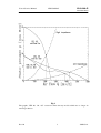
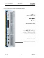
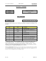
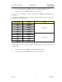
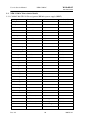
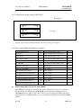
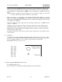
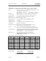
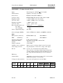
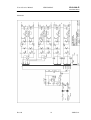
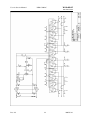
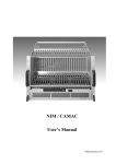
NIM / CAMAC
Crates
User & Service Manual
*00585.A1
User & Service Manual
NIM CAMAC
W-Ie-Ne-R
Plein & Baus GmbH
General Remarks
The only purpose of this manual is a description of the product. It must not be
interpreted as a declaration of conformity for this product including the product and
software.
W-Ie-Ne-R revises this product and manual without notice. Differences of the
description in manual and product are possible.
W-Ie-Ne-R excludes completely any liability for loss of profits, loss of business,
loss of use or data, interrupt of business, or for indirect, special incidental, or
consequential damages of any kind, even if W-Ie-Ne-R has been advised of the
possibility of such damages arising from any defect or error in this manual or
product.
Any use of the product which may influence health of human beings requires the
express written permission of W-Ie-Ne-R.
Products mentioned in this manual are mentioned for identification purposes only.
Product names appearing in this manual may or may not be registered trademarks or
copyrights of their respective companies.
No part of this product, including hardware and software can be reproduced,
transmitted, transcribed, stored in a retrieval system, or translated into any language
in any form by any means without the express written permission of W-Ie-Ne-R.
UEN 04 equipped with UEP 15
Dec-10
I
*00585.A1
User & Service Manual
W-Ie-Ne-R
NIM CAMAC
Plein & Baus GmbH
W-Ie-Ne-R
Plein & Baus GmbH
declare under our own responsibility that the product
declarons sous notre seule responsabilité que le produit
dichiariamo sotto nostra esclusiva responsabilitá che il prodotto
erklärt in eigener Verantwortung, dass das Produkt
NIM / CAMAC – Power Supply
CEP 22M, 10M88, 10M52, 10M53, 10M66
Items: 0331.1xxx, 0331.2xxx
to which this declaration relates, is in conformity with the following standards or
nominative documents:
auquel cette déclaration se refait, est conforme aux normes ou aux autres
documents normatifs:
al quale si riferisce la dichiarazone, è conforme alle seguenti norminative:
auf das sich diese Erklärung bezieht, mit den folgenden Normen oder normativen
Dokumenten übereinstimmt:
1.
EN 50 081-2 (EN 50 022 Cl. B)
2.
EN 50 082- 1
3.
EN 60950
Conditions:
Use in conformity of the definitions inside a crate, which is mounted
inside a closed 19” box and equipped with fully closed slots by front
panels. Otherwise provisions have to be foreseen by the user that
NIM connectors become untouchable (110VAC secondary has been
wired to NIM connectors!)
Admitted for powering by industrial mains only.
Bedingungen: Bestimmungsgemäßer Gebrauch im Crate, bei dem alle Slots mit
Frontplatten bestückt sind und das Bin in ein geschlossenes 19”Gehäuse eingebaut ist.
Zugelassen für Anschluß an industrielle Netzversorgungen.
Name and signature of authorized person
Nome et signature du signataire autorisé
Nome e firma della Persona autorizzata
Name und Unterschrift des Befugten
Place and date
Lieu et date
Luogo e data
Ort und Datum
26. Nov. 2003
Dipl. Ing. Jürgen Baus
51399 Burscheid
Director
Muellersbaum 20
www.wiener-d.com
Dec-10
Germany
II
*00585.A1
User & Service Manual
W-Ie-Ne-R
NIM CAMAC
Plein & Baus GmbH
W-Ie-Ne-R
Plein & Baus GmbH
declare under our own responsibility that the product
declarons sous notre seule responsabilité que le produit
dichiariamo sotto nostra esclusiva responsabilitá che il prodotto
erklärt in eigener Verantwortung, dass das Produkt
NIM Compact, Slot Power Supply UEP 15
Items: 0330.2150, 0330.9007, 0330.9007B
to which this declaration relates, is in conformity with the following standards or
nominative documents:
auquel cette déclaration se refait, est conforme aux normes ou aux autres
documents normatifs:
al quale si riferisce la dichiarazone, è conforme alle seguenti norminative:
auf das sich diese Erklärung bezieht, mit den folgenden Normen oder normativen
Dokumenten übereinstimmt:
4.
EN 50 081-1 (EN 50 022 B)
5.
EN 50 082- 1
6.
EN 61 000-3-2, -3-3
7.
EN 60 950
Conditions:
Use in conformity of the definitions inside a crate, which is mounted
inside a closed 19” box and equipped with fully closed slots by front
panels. Otherwise provisions have to be foreseen by the user that
NIM connectors become untouchable (110VAC secondary has been
wired to NIM connectors!)
Bedingungen: Bestimmungsgemäßer Gebrauch im Crate, bei dem alle Slots mit
Frontplatten bestückt sind und das Bin in ein geschlossenes 19”Gehäuse eingebaut ist.
Andernfalls muß der Anwender Vorkehrungen zum
Berührungsschutz der NIM Stecker treffen (110VAC sec. ist auf NIM
Stecker geführt!)
Name and signature of authorized person
Nome et signature du signataire autorisé
Nome e firma della persona autorizzata
Name und Unterschrift des Befugten
Place and date
Lieu et date
Luogo e data
Ort und Datum
22. July 2004
Dipl. Ing. Jürgen Baus
51399 Burscheid
Director
Muellersbaum 20
www.wiener-d.com
Dec-10
Germany
III
*00585.A1
User & Service Manual
W-Ie-Ne-R
NIM CAMAC
Plein & Baus GmbH
W-Ie-Ne-R
Plein & Baus GmbH
declare under our own responsibility that the product
declarons sous notre seule responsabilité que le produit
dichiariamo sotto nostra esclusiva responsabilitá che il prodotto
erklärt in eigener Verantwortung, dass das Produkt
CAMAC – Power Supply CS 236
Items: 0341.2007
to which this declaration relates, is in conformity with the following standards or
nominative documents:
auquel cette déclaration se refait, est conforme aux normes ou aux autres
documents normatifs:
al quale si riferisce la dichiarazone, è conforme alle seguenti norminative:
auf das sich diese Erklärung bezieht, mit den folgenden Normen oder normativen
Dokumenten übereinstimmt:
8.
EN 50 081 – 1 (EN 50 022 B)
9.
EN 61 000 –3 –2, 3 –3, 4 –1… 6, 4 -11
10.
EN 50 082 – 1
Conditions:
Use in conformity of the definitions inside a crate, which is mounted
inside a closed 19” box and equipped with fully closed slots by front
panels. Admitted for powering by all mains.
Bedingungen: Bestimmungsgemäßer Gebrauch im Crate, bei dem alle Slots mit
Frontplatten bestückt sind und das Bin in ein geschlossenes 19”Gehäuse eingebaut ist.
Zugelassen für Anschluß an alle Netzversorgungen
Name and signature of authorized person
Nome et signature du signataire autorisé
Nome e firma della persona autorizzata
Name und Unterschrift des Befugten
Place and date
Lieu et date
Luogo e data
Ort und Datum
11 January 2002
Dipl. Ing. Jürgen Baus
51399 Burscheid
Director
Muellersbaum 20
www.wiener-d.com
Dec-10
Germany
IV
*00585.A1
User & Service Manual
NIM CAMAC
W-Ie-Ne-R
Plein & Baus GmbH
Table of contents:
1
General Information
1.1
NIM-CAMAC bins
NIM Bin UEN 04
1
1.1.2
NIM Bin UEN 01
1
1.1.3
NIM Bin UEN 03
1
1.1.4
CAMAC Bin UEC 01VH
2
Fan Tray UEL 03 (LX Fan tray)
1.2.1
1.3
2
UEL 03M frontpanel, operating and monitoring functions
4
UEP / CEP and PS / CS power supplies
1.3.1
5
UEP 15 NIM Power Supply
5
1.4
Power supply cooling
Operation, Function and Control
5
5
2.1
5
Fan tray operation and control
2.1.1
Function of fan tray switches and information of the LEDs
5
2.1.2
Programming of the fan tray UEL 03 (In connection with PS 236)
6
2.1.3
Programming of the fan tray UEL 03 (In connection with UEP XX(CEP))
6
2.1.4
Remote control (optional)
7
NIM-CAMAC Bin technical details
10
2.2
3
1
1.1.1
1.2
2
1
2.2.1
CAMAC Bin UEC 01 Pin assignment PG 26 to power supply (PG27)
10
2.2.2
NIM UEN 01/03 Pin assignment PG 26 to power supply (PG27)
11
2.2.3
UEN 01 / UEC 01 Pin assignment PG 32 to fan tray (PG 31)
12
Power supplies, Function and adjustments
3.1
12
Power Supply UEP 15
12
3.1.1
Changing of default settings, recalibration
13
3.1.2
UEP 15 and CANbus Remote Monitor
13
3.2
Power Supply UEP (CEP) 10Mxx –22M
13
3.2.1
Regulator boards UEP 10/22
13
3.2.2
Monitoring and alarming signals (UEP 10/21/22/52/53/55/65)
14
3.2.3
Temperature sensors
14
Dec-10
V
*00585.A1
User & Service Manual
NIM CAMAC
W-Ie-Ne-R
Plein & Baus GmbH
3.2.4
Calibration of output voltage (UEP 10, 52, 53, 66)
14
3.2.5
Calibration of output voltage (UEP 21/22)
15
3.2.6
Pin assignment PG 28 for M-power supplies
15
3.3
Power supply PS (CS) 236, 3U max. 1900W
15
3.3.1
Adjustment
16
3.3.2
Pin assignment PG 28 for PS / CS 236
16
APPENDIX A : Technical details UEP 10M88, 10M52. 10M53, 10M66
17
APPENDIX B : Technical details UEP 22 M
18
APPENDIX C : Technical details PS 236
19
APPENDIX D : Technical Details of UEP 15
20
Dec-10
VI
*00585.A1
User & Service Manual
NIM CAMAC
W-Ie-Ne-R
Plein & Baus GmbH
1
General Information
All W-Ie-Ne-R NIM and CAMAC Crates consist of a bin, a fan tray (except UEN 03 and
UEN 04) and a power supply. The NIM power supplies are (almost) always linear regulated,
while the CAMAC power supplies are either in linear- (till 600W) or switching low noise
technology.
1.1
NIM-CAMAC bins
1.1.1 NIM Bin UEN 04
The UEN 04 is a 5U NIM-bin for 10 (resp. 5 for the transportable version) NIM-modules.
The power supply UEP 15 has to be plugged frontally in the 2(1/2) slots at the right side (slot
11, 12 +). The bin is equipped with 12 high-quality long-life NIM connectors, which are
completely wired parallel (+/-6V, +/-12V, +/-24V, Ground, 115VAC, Clean Earth). The
installed connector pins are made of massive brass, gold plated. The connector foreseen for
connecting the power supply has additional voltage pins paralled for +/-6V.
Low voltage power lines are separately wired with large cross section from power supply
connector to the middle of the NIM Module connector board to keep the voltage drop as low
as possible since sense lines for voltage drop compensation are not foreseen.
Dimensions (whd): 483mm (=19″) x 310mm x 340mm
1.1.2 NIM Bin UEN 01
The UEN 01 is a 7U NIM-bin for 12 high powered NIM-modules. The power supply has to
be plugged in and locked from the rear side. For the fan tray unit a space of 2U high is
foreseen, to bear any kind of fan units which are designed according to the relevant CERN
spec. The bin is equipped with 12 high-quality long-life NIM connectors, which are
completely wired parallel. The installed connector pins are made massive brass, gold plated.
Dimensions (whd): 483mm (=19″) x 310mm x 525mm (with power supply max 570mm),
weight 11,4 kg
1.1.3 NIM Bin UEN 03
The NIM-bin UEN 03 is a 5U NIM-bin for 12 NIM-modules according to the NIM
specification. The wiring and mechanic accords to CERN spec. The frontpanel is equipped
with main switch, control LEDs and test sockets for all voltages. The UEN 03 has no space
for a fan tray. The power supply, UEP (CEP) 10/21/22 will be mounted on its rearside. The
installed connector pins are made massive brass, gold plated.
Dimensions (whd): 483mm (=19″) x 222mm x 525mm (with power supply max. 570mm),
weight: 9,2 kg
All bins have additional free pins paralled to ±12V for 26A current capability
Dec-10
1
*00585.A1
User & Service Manual
NIM CAMAC
W-Ie-Ne-R
Plein & Baus GmbH
Switches:
POWER ON/OFF
main switch for power supply
Indicators:
AC POWER
STATUS
main switch integrated
green LED lights if all voltages are within the limits*
OVERHEAT
yellow LED lights if an overheat in the power supply occur
OVERLOAD
red LED lights if an over-current is detected
1.1.4 CAMAC Bin UEC 01VH
The CAMAC-bin UEC 01 VH is a 7U CAMAC-crate for 25 CAMAC-modules according to
CERN-CAMAC-NOTE 46-04 and with the additional Y1/Y2 (current) lines parallel to
±6V for 80 A capability and with the additional free pins paralled to ±12V for 26A max.
The module connectors have been centered by metal-guides, before touching the dataway
plugs. Power supply plugged in and locked from rear side, fan tray from front side.
Dimensions (whd): 483mm (=19″) x 310mm x 525mm (with power supply 570mm)
1.2
Fan Tray UEL 03 (LX Fan tray)
Except the UEN 03and UEN 04 bins, all NIM and CAMAC Crates are equipped with
UEL03 fan tray, which conforms the CERN specification entirely and adds some interesting
features, like variable fan speed, alphanumerical display etc.
The W-Ie-Ne-R UEL 03 can be used in all NIM or CAMAC crates which are strongly in
conformity with the CERN standards. Three built-in DC-fans with variable fan speed
produce a sufficient air flow to dissipate the heat produced by the plugged in NIM or
CAMAC modules. The micro-processor based fan tray unit is equipped with an
alphanumeric display to inform about voltages, currents, temperatures, power and fan speed.
In case of malfunctions this display can be used as a diagnostic system for trouble shooting.
If used together with the PS 236 W-Ie-Ne-R high power CAMAC power supply, software
controlled current limits can be defined by the help of the front panel display and switches.
Additionally the unit can be equipped with an interface for crate remote control (IEC, HSCAENET, or CANbus).
The fan-tray can be operated in two different air inlet modes.
In the standard mode the air is taken from the front and then pushed upwards to the modules.
A bottom side air inlet for full cooling efficiency can be reached by removing the bottom
plate of the fan-tray and mounting an optional front cover. The maximal air flow reached in
this mode is greater then 540 m3/h and shows a good homogeneity. Thus, up to 1650 W may
be dissipated by this air flow. As depicted in fig. 1 the maximum air flow as well as the static
pressure depends on the air resistance given by the plugged in modules.
Dec-10
2
*00585.A1
User & Service Manual
NIM CAMAC
W-Ie-Ne-R
Plein & Baus GmbH
Fig. 1
The graphs “UEL 01, 02, 05” concerns former fan tray models which are no longer in
current production.
Dec-10
3
*00585.A1
User & Service Manual
W-Ie-Ne-R
NIM CAMAC
Plein & Baus GmbH
1.2.1 UEL 03M frontpanel, operating and monitoring functions
CANbus Interface Connector
Dec-10
4
*00585.A1
User & Service Manual
NIM CAMAC
W-Ie-Ne-R
Plein & Baus GmbH
1.3
UEP / CEP and PS / CS power supplies
The difference between an UEP XX and an CEP XX power supply is, that the UEPs fulfill
the CERN-Standard, while the CEP’s fulfill the CE standard,what concerns the AC-mains
interconnection of power supply and fan tray. Both types are linear regulated and unless
nothing else is mentioned all statements made for an UEP XX are also valid for a CEP XX.
CEP power supplies are compatible to CEL fan trays only!
The PS 236 XXX and the CS 236 XXX power supplies are designed in low noise switching
technology. The PS 236 XXX fulfills the CERN standard and the
CS 236 XXX the CE standard. Unless nothing else is mentioned, all statements made for a
PS 236 XXX are also valid for a CS 236 XXX.
1.3.1 UEP 15 NIM Power Supply
The UEP 15 is a 2 1/2 NIM size plug-in power supply for use in NIM compact /portable bins
UEN 04 with all 6-DC voltages and 115VAC 0,2A with a maximum of 150W continuous
power output.
UEP 15 is fully CE compliant. Monitoring and control is simpler designed and is equipped
with a cut-off protection for overload and overtemperature as well as over- and undervoltage.
The front panel is equipped with the mains switch and control LEDs for status and failure.
The power distribution is done within the NIM bin UEN 04 by parallel wiring of the NIM
connectors. UEP 15 is also able to work in any NIM bin at any slot to power the other
paralled NIM connectors.
Do not use this slot power supply in a NIM bin, when any other power supply is connected
to that concerned NIM bin!
1.4
Power supply cooling
UEP/CEP 10Mxx, UEP 15 and PS/CS 236 are equipped with sufficient long life DC blower
to provide perfect cooling of the unit to avoid overheating under all specified conditions.
UEP/CEP 22M is designed for convection cooling. With the help of forced cooling air (by
extern situated blower) the output performance of UEP 22M can be boosted up to 400W.
2
Operation, Function and Control
2.1
Fan tray operation and control
2.1.1 Function of fan tray switches and information of the LEDs
Switches:
POWER ON/OFF
main switch for ventilation
MODE SELECT
selection switch to choose items and values
for fan tray and power supply and control
FAN SPEED
push button for stepwise in-or decrease fan
speed
FAN AUTO OFF
If this switch is used, the crate will still be
powered, even if there is a fan failure.
LED indicators:
Dec-10
5
*00585.A1
User & Service Manual
NIM CAMAC
W-Ie-Ne-R
Plein & Baus GmbH
green large LED lights , if POWER is on
AC POWER
STATUS
green LED lights if all voltages are within
the limits
FAN FAIL
yellow LED lights if a fan failure is
recognized
OVERHEAT
yellow LED lights if an overheat in the
power supply occurs
FAN SPEED
red control LED for reduced fan speed
(below 3000 rpm)
FAN AUTO OFF
red control LED for “only warning after fan
failure” mode (DC off after failure disabled)
2.1.2 Programming of the fan tray UEL 03 (In connection with PS 236)
Following steps are necessary to change the factory settings (Umax, Umin, Imax)
• Crate must be switched on
• Choose the channel with the lever-switch ‘MODE SELECT’
• Hold simultaneously the lever-switch ‘MODE SELECT’ and ‘POWER’ in top position
and wait about 10 seconds.
• Choose with ‘MODE SELECT’ what you want to change: Umax, Umin, Imax
• Bring lever ‘POWER ON’ in top position for about 10 seconds.
• Change the value through ‘MODE SELECT’
• Push lever ‘POWER OFF’ down to confirm the new value
• Push lever ‘POWER OFF’ down to come back to the normal working status.
If you want to change the ‘AUTO POWER ON/OFF’ function following steps are necessary:
Crate must be switched on
Use lever-switch ‘MODE SELECT’ until ‘POWER’ is displayed.
•
Hold simultaneously the lever ‘MODE SELECT’ and ‘POWER’ in top position and
wait about 10 seconds.
Change setting by ‘MODE SELECT’
Confirm setting by pushing ‘POWER OFF’
2.1.3 Programming of the fan tray UEL 03 (In connection with UEP XX(CEP))
By following the steps shown at point 2.1.2 you have to change the sensitivity of the
displayed currents on the channels ±12V and ±24V (while 6V channels have 10mV/A):
UEP 10M88:
25mV/A
UEP 10M66:
10mV/A
UEP 22M:
50mV/A
Dec-10
(10M52: 5mV/A at +6V/65A, 10M53: 5mV/A at -6V/65A)
6
*00585.A1
User & Service Manual
NIM CAMAC
W-Ie-Ne-R
Plein & Baus GmbH
2.1.4 Remote control (optional)
W-Ie-Ne-R Fan trays are optionally equipped with a CANbus, IEC (IEEE) or H.S.CAENET interface connector as well as the correspondent interface . For further details see
separate manual 00183.A0.
2.1.4.1
CAN-bus interface operation:
If equipped with the optional CAN-bus interface the front panel offers additional elements
for network operation:
Dec-10
7
*00585.A1
User & Service Manual
W-Ie-Ne-R
NIM CAMAC
Plein & Baus GmbH
UEL (CEL) 03
SWITCHES
ADDR
CAN-bus crate address
LOCAL
not used
LED – INDICATORS
LOCAL
green large LED lights when net is OK
The 9-pin Sub-D connector for CAN-bus interfacing is prepared according to CiA
DS 102-1:
Pin
Line
Comment
1
-
2
CAN_L
3
GND
4
-
reserved by CiA
5
-
reserved by CiA
6
-
7
CAN_H
8
-
9
-
reserved by CiA
CAN_L bus line (dominant low)
Ground
CAN_H bus line (dominant high)
reserved by CiA (failure signal)
To change the CAN-bus address the ADDR switch has to be pressed. The address can be
selected within the range 1 ... 127. The chosen net address is displayed on the fan tray
display. If the display has been showing another parameter (voltage, fan speed, ...) before
changing the net address it will return to the previous display. To close the crate for remote
control the position „CANBUS DISABLED“ has to be chosen.
Within the W-Ie-Ne-R CAN-bus protocol a broadcast call to all connected crates is possible
(see CAN-BUS Interface report) . The address for this general call is factory prepared to 127
however it can be changed by the following procedure:
Dec-10
8
*00585.A1
User & Service Manual
W-Ie-Ne-R
NIM CAMAC
Plein & Baus GmbH
1.
Select display channel „GENERAL CALL“ with MODE SELECT switch.
2.
Switch up or down the ADDR switch to change the value.
If the crate has to be disabled for general call the position „GENERAL CALL OFF“ has to
be selected.
According to the CAN bus specification the data transfer speed depends on the net length as
given within the following table:
Max. Distance
Bit Rate
10 m
1.6 Mbit/s
40 m
1.0 Mbit/s
130 m
500 kbit/s
270 m
250 kit/s
530 m
125 kbit/s
620 m
100 kbit/s
1300 m
50 kbit/s
3300 m
20 kbit/s
6700 m
10 kbit/s
10.000 m
5kbit/s
Type
high- speed
low-speed
To adjust the net speed for a given net length select the bit rate according to this table and
set on the crates:
1.
Select display channel „SPEED“ with MODE SELECT switch.
2.
Switch up or down the ADDR switch to select the required rate.
Dec-10
9
*00585.A1
User & Service Manual
W-Ie-Ne-R
NIM CAMAC
Plein & Baus GmbH
2.2
NIM-CAMAC Bin technical details
2.2.1 CAMAC Bin UEC 01 Pin assignment PG 26 to power supply (PG27)
chassis ground
65
+6V return
43-44-45-46-70
220V phase switch
74
-6V
47-48-49-50-67
220V phase mains
75 (not CE versions)
-6V return
51-52-53-54-71
220V neutral switch
76
+12V
55
220V neutral mains
77 (not CE versions)
+12V return
56
117VAC neutral
78
-12V
57
117VAC phase
79
-12V return
58
+12V*
80 (+200V)
+24V
59
+200V return
82
+24V return
60
power failure
1
-24V
62
overload warning
2
-24V return
63
overheat warning
3
0V monitor
5
buzzer warning
4
Y1 current
7 (N.C.)
Y2 sensing
28 (N.C.)
Y1 current return
8 (N.C.)
Y2 sensing return
27 (N.C.)
Y2 current
10 (N.C.)
+6V sensing
29
Y2 current ret
11 (N.C.)
+6V sensing return
26
clean earth
64
-6V sensing
30
+6V current
12
-6V sensing return
27
+6V current return
13
+12V sensing
31
-6V current
14
+12V sensing return
26
-6V current return
15
-12V sensing
32
+12V current
16
-12V sensing return
27
+12V current return
17
+24V sensing
33
-12V current
18
+24V sensing return
26
-12V current return
20
-24V sensing
34
+24V current
21
-24V sensing return
27
+24V current return
22
+6V*
35 (Y1)
-24V current
23
+6V*
36 (Y1 return)
-24V current return
24
-6V*
37 (Y2)
Y1 sensing
25 (N.C.)
-6V
38 (Y2 return)
Y1 sensing return
26 (N.C.)
+6V*
39-40-41-42-66
status warning
72
-12V*
73
Dec-10
10
*00585.A1
User & Service Manual
W-Ie-Ne-R
NIM CAMAC
Plein & Baus GmbH
2.2.2 NIM UEN 01/03 Pin assignment PG 26 to power supply (PG27)
Function
PG 26
chassis ground
65
+6V sensing
29
220V phase switch
74
+6V sensing return
26
220V phase mains
75 (not CE versions)
-6V sensing
30
220V neutral switch 76
-6V sensing return
27
220V neutral mains
77 (not CE versions)
+12V sensing
31
117 V a.c. neutral
78
+12V sensing return
26
117 V a.c. phase
79
-12V sensing
32
+12V *
80 (+200V)
-12V sensing return
27
+200V return
82
+24V sensing
33
power failure
1
+24V sensing return
26
overload warning
2
-24V sensing
34
overheat warning
3
-24V sensing return
27
buzzer warning
4
+6V
39-40-41-42-66
0V monitor
5
+6V return
43-44-45-46-70
clean earth
64
-6V
47-48-49-50-67
+6V current
12
-6V return
51-52-53-54-71
+6V current return
13
+12V
55
-6V current
14
+12V return
56
-6V current return
15
-12V
57
+12V current
16
-12V return
58
+12V current return
17
+24V
59
-12V current
18
+24V return
60
-12V current return
20
-24V
62
+24V current
21
-24V return
63
+24V current return
22
status warning
72
-24V current
23
0V signal
5
-24V current return
24
-12V *
73
* special pin out as an extension to Cern spec. version.
Dec-10
11
*00585.A1
User & Service Manual
W-Ie-Ne-R
NIM CAMAC
Plein & Baus GmbH
2.2.3 UEN 01 / UEC 01 Pin assignment PG 32 to fan tray (PG 31)
3
Chassis ground
h
+12V current return
R
220V phase switch
AA
-12V current
S
220V phase mains
BB (not CE versions)
-12V current return
T
220V neutral switch
CC
+24V current
U
220V neutral mains
DD (not CE versions) +24V current return
V
117V a.c. neutral
EE
-24V current
W
117V a.c. phase
FF
-24V current return
X
+200V
HH
+6V
a
overload warning
B
-6V
b
overheat warning
C
+12V
c
buzzer warning
D
-12V
d
+6V current
K
+24V
e
+6V current return
L
-24V
f
-6V current
M
0V voltage monitor.
k
-6V current return
N
0V voltage warning
j
+12V current
P
status warning
A
Power supplies, Function and adjustments
All Power Supplies will be shipped with proper adjusted DC output voltages as company
settings. Readjustments for linear regulated power supplies can be done via corresponding
voltage trimmer. Since all power supplies have been equipped with window comparators
with min. and max. threshold for the “Status Good” signal. Threshold exceeding activates
trip off. While the status window for 22M and 10Mxx types are fix (+/-3% window), it is
adjustable with UEP 15 and PS/CS236. All types except UEP 15 are outfitted with crowbar
over voltage protection, also with adjustable response threshold as well as with sense lines
for each DC output.
3.1
Power Supply UEP 15
When all six DC voltages are in their limits, the green “Power On” LED is active. If one ore
more DC outputs exceed the status window thresholds a cut off relay will disconnect the
transformer from AC mains. The relay locks and the red failure LED starts to light.
The red failure LED is recessed mounted to prevent any mechanical damage of it’s
body since it is operated at mains potential !
Release of the locking circuit after fault clearance by switch off or disconnect from mains for
approximately 10 seconds.
Dec-10
12
*00585.A1
User & Service Manual
W-Ie-Ne-R
NIM CAMAC
Plein & Baus GmbH
3.1.1 Changing of default settings, recalibration
UEP 15 allows to adjust the six DC output voltages and the Limits of the status window.
Current limits are given by the used voltage regulators.
The trim points are accessible after removing
+24V
-24V
+12V –12V
+6V -6V
Status Window Comparator
Lower-Level-Upper
3.1.2 UEP 15 and CANbus Remote Monitor
On request UEP 15 can be outfitted with a CANbus interface. The functions are limited to
On/Off and monitoring of DC voltages only.
3.2
Power Supply UEP (CEP) 10Mxx –22M
3.2.1 Regulator boards UEP 10/22
The six control circuits for the ±6V, ±12V, ±24V are of the similar design.
All outputs are short circuit protected by means of an electric circuit providing a fold back
characteristic. Due to the additional status control the unit will trip off normally in case of
overload. The foldback behavior becomes active only when:
1. The status window circuit is faulty
2. The status window circuit is readjusted
3. The control circuit is disabled (PG 28 M- monitoring, pin 28)
Dual tracking:
For some applications of the power supply it is important that during turn on or turn
off transients opposite voltages have the same absolute value. This feature is
Dec-10
13
*00585.A1
User & Service Manual
W-Ie-Ne-R
NIM CAMAC
Plein & Baus GmbH
achieved by a small additional circuit which clamps the deviation to nearly ±0.3V.
Any higher nonsymmetrical output voltage shifts this bias of the regulator to
nonsymmetrical levels and the voltage control circuit will regulate both outputs
nearly symmetrical to the ground.
The total regulator circuit comprises 3 integrating control loops for:
output voltage
fold back characteristic
dual tracking
3.2.2 Monitoring and alarming signals (UEP 10/21/22/52/53/55/65)
In case of over temperature at fan tray or bin controller a yellow LED lights, in case of
overload a red LED lights. In both cases a buzzer warns the user; Inside the power supply the
power transformer will be disconnected from mains by a locking relay. The unit can be
restarted after fault clearance by switch off or disconnect from mains for a couple of seconds
or by feeding 5V to the rearming input at PG 28 connector.
Temperature warning is a special option which operates the over temperature LED before
the max. temp. level is reached.
3.2.3 Temperature sensors
All linear regulated power supplies of 10M and 22M series are controlled with 4 independent
temperature sensors. Two are placed at the top of the heat sink, one is placed on the control
board and one sensor is inside the transformer. If one of this four sensors exceeds the
maximum temperature-level, the temp. off function will interrupt the AC mains circuit.
3.2.4 Calibration of output voltage (UEP 10, 52, 53, 66)
⇓
front side
+24V +12V +6V
-24V
-12V
-6V
(top view)
⇑
back side
Voltages can be set by using the trim-pots on the top of the power supply
Dec-10
14
*00585.A1
User & Service Manual
W-Ie-Ne-R
NIM CAMAC
Plein & Baus GmbH
3.2.5 Calibration of output voltage (UEP 21/22)
⇓
+6V
-6V
+12V
-12V
+24V
-24V
front side
(top view)
⇑
back side
Voltages can be set by using the trim-pots on the top of the power supply
3.2.6 Pin assignment PG 28 for M-power supplies
3.3
Power failure monitor
12
-12V current monitor (N.C.)
32
0V signal
8
-12V current return monitor (N.C.)
33
Status monitor
11
+24V current monitor (N.C.)
13
Status return monitor
23
+24V current return monitor (N.C.)
14
0V = Inhibit
26
-24V current monitor (N.C.)
19
0V = Disable
28
-24V current return monitor (N.C.)
20
Rearming +5V input
35
+6V monitor
3
Rearming +5V return
34
-6V monitor
4
+6V current monitor (N.C.)
15
+12V monitor
2
+6V current return monitor (N.C.)
16
-12V monitor
5
-6V current monitor (N.C.)
17
+24V monitor
1
-6V current return monitor (N.C.)
18
-24V monitor
6
+12V current monitor (N.C.)
30
0V monitor
9
+12V current return monitor (N.C.)
31
(DC-off)
Power supply PS (CS) 236, 3U max. 1900W
The CAMAC power supply of the new 236 series is entirely micro-processor controlled
designed in the very high density W-Ie-Ne-R- cavity technology, which provides an
extremely low noise output voltage. Due to these low noise figures the PS/CS 236 can be
used trouble free for NIM application, too, in combination with the special outfitted UEN01
VH bin.
Dec-10
15
*00585.A1
User & Service Manual
W-Ie-Ne-R
NIM CAMAC
Plein & Baus GmbH
The PS 236 considers CERN Specification, while the CS 236 is designed according to the
CE rules. The predominant detail is the wiring of the mains between power supply and fan
tray, which has to be outfitted either as CERN – version (=PS types) or as CE- version (=CS
types).
CE types feature a separate powercord, plugged on top of the power supply box and to the
rear side of the fan tray, where it is fixed by a cable gland.
EMC compatibility is accomplished by meeting the EN 50 022, EN 61000-6-3 for generic
emissions as well as the EN 61000-6-2 for immunity. The insulation performs the EN 60
950, ISO 380, VDE 0805 (SELV)! Furthermore are considered UL 1950, UL 1012, UL 478,
C 22.2.950, C 22.2.220/234.
The power packs are readily replaceable. The maximum output power is 1900W if mains
voltage is >150VAC.
Turning on the power supply all voltages reach the nominal values nearly simultaneously
within 50ms ±2.5ms whereby the voltages versus time curve shows a monotonic behavior.
During any trip off the outputs will be discharged by the crowbars to a value of 10% of the
nominal voltages within 2,5ms.
By the help of the remote sense lines an output voltage compensation of at least 0.5V at full
load is possible.
3.3.1 Adjustment
All output voltages can be adjusted manually using the rotary switches on the power supply
top. It has to be considered that the programmed “Status-Window” with Umin and Umax must
be set accordingly. Otherwise over- or under-voltage will lead to DC trip off.
Programming features see above 2.12
U2= +24V
U6= –24V
U1= +12V
U5= –12V
U4= - 6V
U0= +6V
U7= NC
U8= NC
Channel selection
(0:U0...7:U7)
Adjustment
3.3.2 Pin assignment PG 28 for PS / CS 236
See diagram below 2.4.6
PS / CS 236 units are standardized with fully M-type monitoring facilities.
Dec-10
16
*00585.A1
User & Service Manual
W-Ie-Ne-R
NIM CAMAC
Plein & Baus GmbH
APPENDIX A: Technical details UEP 10M88, 10M52. 10M53, 10M66
Input:
230VACnom +10-15%, 48-63 Hz, inrush current limited to <15A,
with mains filter and fuse protection
Type 10M88B
115VACnom,
Type 10M88J
100VACnom,
Derating:
600W output up to 42°C, with a derating of 2%/K up to 60°C
Noise and ripple:
full load < 0.6mV eff, <3mVpp, 1mV at 80% rated power
Regulation load:
10 to 100% Uout < 0.05%, line ±10%Uout < 0.02%
Recovery time: load change 10% to 100% < 0.15 ms
Output impedance:
static < 0.2mOhm, dynamic at 100kHz < 0.3 Ohm
Temperature error:
< 5*10-5/K
Thermal protection:
overheating protection by thermal sensors (4 fold),
Current limit:
adjusted to rated current
Characteristics: short circuit protected by fold back characteristic, short circuit
current < 3A resp. 1A, reverse bias diodes.
DC off:
<5ms if >+/-3% deviation from nominal values (status window),
after overload, overvoltage, undervoltage, fan fail and overheat.
DC Outp.Voltages:
calibration range >±5% rated voltage, dual tracking for all ±DC
outputs overvoltage protection (crow bar), ±6V, ±12V, ±24V
default calibration
±7.3V, ±14.5V, ±28.5V
M-monitoring:
with status-signal and status-relay, rearming and
inhibit input, power-fail-signal, remote monitoring acc. to
CERN-CAMAC-note 46-04
Output voltages, currents and total power:
Outputs
+6V
-6V
+12V
-12V +24V
UEP 10M88
45A
45A 8A
8A 8A
CEP 10M88
45A
45A 8A
UEP 10M52
65A
CEP 10M52
-24V
115 VAC
Max Power
8A
0.5A
600W
8A 8A
8A
0,5A
600W
32A
---------------- 6A
6A
0.5A
650W
65A
32A
---------------- 6A
6A
0,5A
650W
UEP 10M53
32A
65A
---------------- 8A
8A
0.5A
650W
CEP 10M53
32A
65A
---------------
8A
8A
0,5A
650W
UEP 10M66
20A
20A 15A
15A 4A
4A
0.5A
600W
CEP 10M66
20A
20A 15A
15A 4A
4A
0,5A
600W
Note: The total Power consumption of the same polarity (+ or -) should not exceed 400W.
Example 10M88 :
Dec-10
+6V/45A=270W
+12V/8A= 96W
+24V/8A=192W
not allowed: Σ=558W
+6V/40A=240W
+12V/4A= 48W
+24V/4A= 96W
allowed: Σ=384W
17
*00585.A1
User & Service Manual
W-Ie-Ne-R
NIM CAMAC
Plein & Baus GmbH
APPENDIX B: Technical details UEP 22 M
Input:
230V (or 115V) +10%-15%, 48-63Hz,
inrush current limited to < 15/30A
Type 22M B
115VACnom,
Type 22M J
100VACnom,
Derating:
300W full power up to 50°C, derating 2%/K up to 60°C
Noise and ripple:
full load < 0.6mV eff, < 3mVpp, 1mV at 80% rated power
Regulation:
10 to 100% Uout < 0.05%, line ±10%Uout < 0.02%
Recovery time:
load change 10% to 100% < 0.15 ms
Output impedance:
static < 0.2mOhm, dynamic at 100kHz < 0.3 Ohm
Temperature error:
<5*10-5/K
Thermal protection:
overheating protection by thermal sensors (4 fold),
Current limit:
adjusted to 115% of rated current, adjusting range ±20%
Characteristics:
short circuit protected by fold back characteristic, short circuit
current < 3A, reverse bias diodes.
DC off:
<5ms if >+/-3% deviation from nominal values (status window),
after overload, overvoltage, undervoltage, fan fail and
overheat.
DC Outp.Voltages:
calibration range >±5% rated voltage, dual tracking for all ±DC
outputs overvoltage protection (crow bar), ±6V, ±12V, ±24V
default calibration
±7.3V, ±14.5V, ±28.5V
M-monitoring
status-signal and status-relay, rearming and inhibit input,
power-fail-signal, remote monitoring acc. to
CERN-CAMAC-note 46-04
Output voltages, currents and total power
Outputs
+6V
-6V
UEP 22M
17A
17A
3.4A
CEP 22M
17A
17A
3.4A
Dec-10
+12V
-12V
+24V
-24V
115 VAC
Max. Power
3.4A 3.4A
3.4A
0.5A
300W
3.4A 3.4A
3.4A
0,5A
300W
18
*00585.A1
User & Service Manual
W-Ie-Ne-R
NIM CAMAC
Plein & Baus GmbH
APPENDIX C: Technical details PS 236
Input:
World range 92...265VAC/<16A, 47-63Hz
Inrush current:
limited by soft start to max 16A
Power factor:
CE 0,99 nominal EN 61 000-3,-2
Isolation, safety:
CE EN 60950, ISO 380, UL 1950, CSA 22.2950
Regulation static:
(6V, 12V, 24V):
< 15mV (±100% load, ±15% mains)
< 0.05% (±100% load, ± 15% mains)
Regulation dynamic:
(6V, 12V, 24V):
< 100mV (±25% load)
< 0.7% (±25% load)
Recovery time ±25% load:
6V / 80A:
12V, 24V/10A:
within ±1%
0.2ms
1.0ms
Sense compensating range:
min. 0.5V
Noise and ripple (PARD):
inside a UEC01 bin: <10mVpp (0-20MHz) <3mVrms
within 0.1%
0.5ms
EMI
RFI-rejection (emission):
CE EN 50022-1 (B)
EN 61000-6-3
EMC
CE
EN 61000-6-2
(immunity):
Operation temperature:
Temperature limits:
Storage:
Temp.-coefficient:
0...50° without derating
heat sinks cut off 110°C, ambient 70°C
-30°C up to 85°C
< 0.2%/10K
Stability (const. conditions):
10mV or 0.1% / 24 hours, 25mV or 0,3% / 6 month
Overvoltage crow bar:
trip off adjusted to 125% nom. voltage, each output
DC off:
<5ms if >+3% -5% deviation from nominal values,
after overload, overvoltage, undervoltage, fan fail and
overheat. Output capacitors will be discharged by crow
bars. Trip off points adjustable, processor controlled.
Efficiency:
80%
Current limits:
adjustable to any lower level, max. 115% of nom values
(UEL 03 front panel or via network)
Voltage rise characteristics:
monotonic and synchronic, rise time 50ms
Output
PS/CS
236
Dec-10
-6V 12V
-12V
24V
-24V
at 230VAC
max.
115VAC
max.
100VAC
max.
80A 80A 20A
20A
10A
10A
1900W
1500W
1300W
6V
19
*00585.A1
User & Service Manual
W-Ie-Ne-R
NIM CAMAC
Plein & Baus GmbH
APPENDIX D: Technical Details of UEP 15
Dimensions:
width 2 1/2 NIM, height 183 mm, depth 249 mm
Weight:
7.5 kg
Mains Input:
CE 100/115 / 210/240 VAC (+-10%), 48 - 63 Hz, intern, taps , EN61 000 –3-2
soft start circuit, mains filter, fuse protection
Isolation:
CE input-output EN60950, ISO 380, VDE 0805, UL1950, C22.2.950
Derating:
Regulation:
Recovery time :
Output impedance:
Noise and ripple:
continuous full power at 40°C, derating 2 %/K up to 60°C
load 10 to 100%
< 0.2% for 6V, <0.1% for 12V / 24V
line +/-10%
∆Uout < 0.02%
load change 10 % to 100%: < 0.15ms
static
< 1.5 mOhm
dynamic
< 0.5 Ohm
+/-6V: 3mVpp, +/-12V: 5mVpp, +/-24V: 10mVpp
Temperature error: < 2 ×10⁻⁴ /K
DC off:
if >+/-3% deviation from nominal values (status window) due to overload,
overvoltage and undervoltage, overheat
.
Thermal protection: overheating protection by thermal switches for each regulator and for
transformer
Current
characteristics:
current limits fixed
constant current in over current mode
reverse bias diodes.
Voltage
characteristics:
calibration range +/- 5 % rated voltage,
adjustment points behind left side panel
over and undervoltage protection for all outputs (+/- 0.3%)
Output voltages, currents and total power
Outputs
+6V
-6V
+12V
-12V
+24V
-24V 115 VAC
Max Power
UEP 15
5A
5A
3A
3A
1,5A
1,5A
0.2A
150W
UEP 15 as
5A
5A
3A
3A
3A
0,5A
0,2A
150W
Dec-10
20
*00585.A1
User & Service Manual
NIM CAMAC
W-Ie-Ne-R
Plein & Baus GmbH
Schematic
Dec-10
21
*00585.A1
User & Service Manual
NIM CAMAC
W-Ie-Ne-R
Plein & Baus GmbH
Dec-10
22
*00585.A1