1
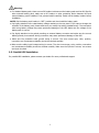
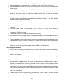
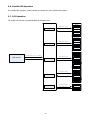
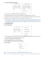
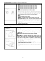
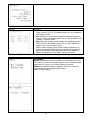
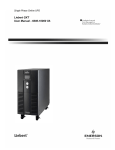
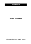
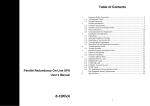
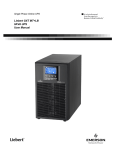
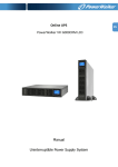
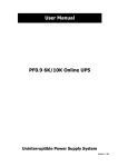
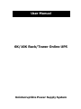
User Manual 6K/10K Rack/Tower Online UPS Uninterruptible Power Supply System Please comply with all warnings and operating instructions in this manual strictly. Save this manual properly and read carefully the following instructions before installing the unit. Do not operate this unit before reading through all safety information and operating instructions carefully. Table of Contents 1. SAFETY AND EMC INSTRUCTIONS ................................................................................................. 1 1-1. TRANSPORTATION AND STORAGE ...............................................................................................................1 1-2. PREPARATION.......................................................................................................................................1 1-3. INSTALLATION ......................................................................................................................................1 1-4. OPERATION .........................................................................................................................................2 1-5. STANDARDS .........................................................................................................................................2 2. INSTALLATION ............................................................................................................................... 3 2-1. UNPACKING AND INSPECTION ...................................................................................................................3 2-2. REAR PANEL VIEW.................................................................................................................................3 2-3. RACK/TOWER INSTALLATION ....................................................................................................................5 2-4. SINGLE UPS INSTALLATION .....................................................................................................................6 2-5. PARALLEL UPS INSTALLATION ..................................................................................................................7 3. OPERATIONS .................................................................................................................................. 8 3-1. OPERATING MODE/STATUS DESCRIPTION ....................................................................................................8 3-2. BUTTON OPERATION ..............................................................................................................................8 3-3. LED INDICATORS ..................................................................................................................................9 3-4. AUDIBLE ALARM ....................................................................................................................................9 3-5. SINGLE UPS OPERATION ........................................................................................................................9 3-6. PARALLEL UPS OPERATION.................................................................................................................... 12 3-7. LCD OPERATION ................................................................................................................................. 12 3-7-1. MAIN INTERFACE (HOME PAGE) ............................................................................................................ 13 3-7-2. OPERATION MENU ............................................................................................................................ 13 4. TROUBLE SHOOTING ................................................................................................................... 21 4-1. WARNING STATUS ............................................................................................................................... 21 4-2. FAULT MODE ...................................................................................................................................... 21 4-3. TROUBLE SHOOTING TABLE .................................................................................................................... 21 5. STORAGE AND MAINTENANCE ..................................................................................................... 24 5-1. STORAGE .......................................................................................................................................... 24 5-2. MAINTENANCE.................................................................................................................................... 24 6. SPECIFICATIONS ......................................................................................................................... 25 1. Safety and EMC instructions Please read carefully the following user manual and the safety instructions before installing the unit or using the unit! 1-1. Transportation and Storage Please transport the UPS system only in the original package to protect against shock and impact. The UPS must be stored in the room where it is ventilated and dry. 1-2. Preparation Condensation may occur if the UPS system is moved directly from cold to warm environment. The UPS system must be absolutely dry before being installed. Please allow at least two hours for the UPS system to acclimate the environment. Do not install the UPS system near water or in moist environments. Do not install the UPS system where it would be exposed to direct sunlight or nearby heater. Do not block ventilation holes in the UPS housing. 1-3. Installation Do not connect appliances or devices which would overload the UPS (e.g. big motor-type equipment)). Place cables in such a way that no one can step on or trip over them. Do not block air vents in the housing of UPS. The UPS must be installed in a location with good ventilation. Ensure enough space on each side for ventilation. UPS has provided earthed terminal, in the final installed system configuration, equipotential earth bonding to the external UPS battery cabinets. The UPS can be installed only by qualified maintenance personnel. An appropriate disconnect device as short-circuit backup protection should be provided in the building wiring installation. An integral single emergency switching device which prevents further supply to the load by the UPS in any mode of operation should be provided in the building wiring installation. Connect the earth before connecting to the building wiring terminal. Installation and Wiring must be performed in accordance with the local electrical laws and regulations. 1 1-4. Operation Do not disconnect the earth conductor cable on the UPS or the building wiring terminals in any time since this would cancel the protective earth of the UPS system and of all connected loads. If the external battery cabinet is connected, the UPS output Anderson connector may be electrically live even if the UPS system is not connected to the building wiring outlet. In order to fully disconnect the UPS system, first press the “OFF” button and then disconnect the mains. Ensure that no liquid or other foreign objects can enter into the UPS system. The UPS can be operated by any individuals with no previous experience. 1-5. Standards * Safety IEC/EN 62040-1 * EMI Conducted Emission...............................:IEC/EN 62040-2 Category C3 Radiated Emission..................................:IEC/EN 62040-2 Category C3 *EMS ESD.........................................................:IEC/EN 61000-4-2 Level 4 RS........................................................ ...:IEC/EN 61000-4-3 Level 3 EFT......................................................... :IEC/EN 61000-4-4 Level 4 SURGE................................................... :IEC/EN 61000-4-5 Level 4 CS........................................................... :IEC/EN 61000-4-6 Level 3 Power-frequency Magnetic field.............. :IEC/EN 61000-4-8 Level 4 Low Frequency Signals............................:IEC/EN 61000-2-2 Warning: This is a product for commercial and industrial application in the second environment-installation restrictions or additional measures may be needed to prevent disturbances. 2 2. Installation There are two types: standard and long-run models. Please refer to the following model table. Model Type Model Type 6KRT Standard model 6KRTL Long-run model 10KRT Standard model 10KRTL Long-run model 2-1. Unpacking and Inspection Unpack the package and check the package contents. The shipping package contains: ● One UPS ● One user manual ● One monitoring software CD ● One RS-232 cable (option) ● One USB cable ● One parallel cable and one share current cable (option) ● One battery cable (option) ● Two sets of tower stands including feet and extensions ● Mounting ears NOTE: Before installation, please inspect the unit. Be sure that nothing inside the package is damaged during transportation. Do not turn on the unit and notify the carrier and dealer immediately if there is any damage or lacking of some parts. Please keep the original package in a safe place for future use. 2-2. Rear Panel View Diagram 1: 6KRT(L)/10KRT(L) Rear Panel Diagram 2: 6KRT(L)/10KRT(L) Input/Output Terminal 3 Diagram 3: Battery Pack Rear Panel 1. RS-232 communication port 2. USB communication port 3. EPO (Emergency Power Off) connector 4. Share current port (for parallel function) 5. Parallel port (for parallel function) 6. Intelligent slot 7. EMBS (External Maintain Bypass Switch) port 8. Cooling fan 9. External battery connector 10. Input circuit breaker 11. Input/Output terminal 12. Input terminal 13. Ground 14. Output terminal 15. Battery pack output circuit breaker 4 2-3. Rack/Tower Installation 2-3-1 Tower Installation The UPS system is shipped with two sets of feet and 6 extensions (2 short extensions plus 4 long extensions) that can be used to tower install the UPS module in 3U or UPS module with one battery bank in 6U. Install UPS module in 3U Step 1 Step 2 Assemble two feet and one short extension as one tower stand shown in step 1. Align the two stands approximately 35cm apart in step 2. Then, put UPS module in the stands as shown in step 3. Step 3 Install UPS module and one battery bank in Step 1 Step 2 6U Assemble two feet and two long extensions as one tower stand shown in step 1. Align the two stands approximately 35cm apart in step 2. Then, put UPS module and battery bank in the stands as shown in step 3. Step 3 5 2-3-2 Rack Installation Please follow below steps to mount UPS into 19” rack or rack enclosure. Step 1: Attach mounting ears to the side Chart 1 mounting holes of UPS using the screws provided and the ears should face forward. Please refer to chart 1. Step 2: Lift the UPS module and slide it into rack Chart 2 enclosure. Attach the UPS module to the rack with screws, nuts and washers (user-provided) through its mounting ears and into the rack rails. Please refer to chart 2. 2-4. Single UPS Installation Installation and wiring must be performed in accordance with the local electric laws/regulations and execute the following instructions by professional personnel. 1) Make sure the mains wire and breakers in the building are enough for the rated capacity of UPS to avoid the hazards of electric shock or fire. NOTE: Do not use the wall receptacle as the input power source for the UPS, as its rated current is less than the UPS’s maximum input current. Otherwise the receptacle may be burned and destroyed. 2) Switch off the mains switch in the building before installation. 3) Turn off all the connected devices before connecting to the UPS. 4) Prepare wires based on the following table: Model 6KRT(L) 10KRT(L) Input 10 8 Wiring spec (AWG) Output Battery 10 10 8 8 Ground 10 8 NOTE 1: The cable for 6KRT(L) should be able to withstand over 40A current. It is recommended to use 10AWG or thicker wire for safety and efficiency. NOTE 2: The cable for 10KRT(L) should be able to withstand over 63A current. It is recommended to use 8AWG or thicker wire for safety and efficiency. NOTE 3: The selections for color of wires should be followed by the local electrical laws and regulations. 6 Warning: ● For standard battery pack, there are one DC breaker to disconnect the battery pack and the UPS. But for other external battery pack, make sure a DC breaker or other protection device between UPS and external battery pack is installed. If not, please install it carefully. Switch off the battery breaker before installation. NOTE: Set the battery pack breaker in “OFF” position and then install the battery pack. ● Pay highly attention to the rated battery voltage marked on the rear panel. If you want to change the numbers of the battery pack, please make sure you modify the setting simultaneously. The connection with wrong battery voltage may cause permanent damage of the UPS. Make sure the voltage of the battery pack is correct. ● Pay highly attention to the polarity marking on external battery connector and make sure the correct battery polarity is connected. Wrong connection may cause permanent damage of the UPS. ● Make sure the protective earth ground wiring is correct. The wire current spec, color, position, connection and conductance reliability should be checked carefully. ● Make sure the utility input & output wiring is correct. The wire current spec, color, position, connection and conductance reliability should be checked carefully. Make sure the L/N site is correct, not reverse and short-circuited. 2-5. Parallel UPS Installation For parallel UPS installation, please contact your dealer for more professional support. 7 3. Operations 3-1. Operating Mode/Status Description Mode/Status UPS Power On Description When UPS is powered on, it will enter into this mode for a few seconds for initializing the CPU and system. AC Mode When the input voltage is within acceptable range, and the UPS is turned on (the inverter is running), the UPS will provide pure and stable sine wave AC voltage. The UPS will also charge the battery in AC mode. When the input voltage is within voltage regulation range and ECO mode is enabled, the UPS will bypass voltage to output for energy saving. If the input voltage is out of the regulation range but it is still within acceptable range of AC mode, the UPS will transfer to inverter supplying the power to load (similar as AC mode). When input frequency is within 46 to 64Hz, the UPS can be set with a constant output frequency (50 Hz or 60 Hz) through the inverter. The UPS will still charge battery at this mode. There is no bypass at this mode. When the input voltage is out of the acceptable range or power failure, and the UPS is turned on (the inverter is running), the UPS will backup power from battery. ECO Mode Converter Mode Battery Mode Bypass Mode Battery Test Mode Warning Status Fault Mode When input voltage is within acceptable range and bypass is enabled, and the UPS (inverter) is not turned on or the inverter can’t support the load, the UPS will supply power to the load through bypass. When the UPS is in AC mode or Converter mode, and the battery test command is enabled through LCD or monitoring software, the UPS will start Battery Test. This operation is used to check the battery status. If some errors occur in the UPS (but it is still running normally), buzzer will alarm and warning code will appear in the LCD for trouble shooting. When fatal error occurs in the UPS, it will beep continuously and go to fault mode. It will display fault codes in LCD. 3-2. Button Operation There are 4 buttons on front panel. Button ON/ENTER OFF/ESC Function Press this button to turn on the UPS. Or press it to confirm the selection in the menu. Press this button to turn off the UPS. Or press it to return to last menu. 8 UP DOWN UP + DOWN Press this button to select the previous item in the menu. Or press this button to jump to previous page in the screen. Or press this button to increase the number in the setting. Press this button to select the next item in the menu. Or press this button to jump to next page in the screen. Or press this button to decrease the number in the setting. To allow LCD display to rotate 90ºautomatically, press these two buttons at the same time. This operation is used to configure the UPS in rack or tower display. 3-3. LED Indicators There are 4 LEDs on front panel to show the UPS working status: Mode LED Bypass Line Battery Fault UPS Power On Bypass mode ● ○ ○ ○ ○ ● ○ ● ○ ○ ● ● ○ ○ ● ○ ● ○ ○ ○ ○ ● ○ ○ AC mode / Converter mode Battery mode Fault mode Battery test mode ECO mode Note: ● means LED is lit; ○ means LED is faded; means LED is flashing. 3-4. Audible alarm UPS status Bypass mode Battery / Battery-test mode (normal battery voltage) Battery / Battery-test mode (low battery voltage) Fault Warnings (except overload) Overload Buzzer status Beeping once every 2 minutes Beeping once every 4 seconds Beeping once every second Beeping continuously Beeping once every second Beeping twice every second Muted Yes Yes Yes Yes No No 3-5. Single UPS Operation 3-5-1. Turn on the UPS with utility power supply (to Line mode) 1) Make sure mains input and battery are connected well, and the battery pack breaker is at “ON” position; Set the external mains input breaker to “ON” position, then the fan will be running and the UPS supplies power to the loads via bypass; (The UPS is operating in Bypass mode.) NOTE: When UPS is in Bypass mode, the output voltage comes directly from utility, so the load is not protected by UPS. To protect the precious load, the UPS should be turned on to Line mode. 2) When LCD is on home page, press the “ON/ENTER” button, LCD will show a prompt page of “Turn On”; Move the arrow to “Yes” by up or down button, then press “ON/ENTER”, the UPS will be starting up with beeping once. You could also enter the “control menu” to select the instruction “Turn On” to startup the UPS. Please refer to the section of “LCD operation”. 3) A few seconds later, the UPS will enter into Line mode; “Line mode” will be displayed on LCD. (In line mode, if the utility power is abnormal, the UPS will transfer to Battery mode without interruption.) 9 3-5-2. Turn on the UPS without utility power supply (to Battery mode) 1) Make sure the battery is connected well and the battery pack breaker is at “ON” position; 2) Press the “ON/ENTER” button to start up the internal power, the UPS will enter into bypass mode without output; 3) When LCD is on home page, press the “ON/ENTER” button, LCD will show a prompt page of “Turn On”; Move the arrow to “Yes” by up or down button, then press “ON/ENTER”, the UPS will be starting up with beeping once. You could also enter the “control menu” to select the instruction “Turn On” to startup the UPS. Please refer to the section of “LCD operation”. 4) A few seconds later, the UPS will enter into Battery mode; “Battery mode” will be displayed on LCD (In Battery mode, it will shutdown automatically when battery is depleted. If the utility power is restored, it will auto restart to Line mode.) 3-5-3. Connect devices to UPS After the UPS is turned on, you can connect devices (load) to the UPS. 1) Turn on the UPS first and then switch on the devices one by one, the LCD panel will display total load level; 2) If inductive loads needed to be connected, such as a printer, the in-rush current should be calculated carefully to see if capacity of the UPS can cover due to the huge starting power consumption of this kind of load; 3) If the UPS is overload, the buzzer will beep twice every second; 4) When the UPS is overload, please remove some loads immediately. It is recommended to have the total loads connected to the UPS less than 80% of its nominal power capacity for system safety; 5) If the overload time is over duration listed in spec at Line mode, the UPS will automatically transfer to Bypass mode. After the overload is removed, it will return to Line mode. If the overload time is over duration listed in spec at Battery mode, the UPS will become fault status. At this time, if bypass is enabled, the UPS will power to the load via bypass. If bypass function is disabled or the input power is not within bypass acceptable range, it will cut off output directly. 3-5-4. Charge the batteries 1) After the UPS is connected to the utility power, the charger will charge the batteries automatically except in Battery mode or during battery test; 2) Suggest to charge batteries at least 10 hours before use. Otherwise, the backup time may be shorter than expected; 3) Make sure the battery numbers setting on the control board (Please refer to the section of changing battery quantity) is consistent with actual connection. 3-5-5. Battery mode operation 1) When the UPS is in Battery mode, the buzzer will beep according to different battery capacity. Normally, the buzzer will beep once every 4 seconds in battery mode, but when the battery voltage drops to the alarm level, the buzzer will beep once per second and the UPS will shut down automatically soon. Users could switch off some non-critical loads to disable the shutdown alarm and prolong the backup time. If there is no more load to be taken off at that time, you have to shut down all loads as soon as possible to protect the devices or save data. Otherwise, there is a risk of data loss or load failure; 2) In Battery mode, if buzzer sounds annoying, you could enter ”Control->Mute” on LCD to silence it. Please refer to the section of “LCD operation”; 3) The backup time of the long-run model depends on the external battery capacity; 10 4) The backup time may change under different environment temperature and load type; 5) The maximum backup time is limited by default 16.5 hours (After discharging 16.5 hours, UPS will shut down automatically to protect the battery). The time could be modified through LCD panel or communication port. 3-5-6. Test the batteries 1) If you need to check the battery status or performance when the UPS is running in Line / Converter / ECO mode, you could enter ”Control->Batt Test” to instruct the UPS to do battery test. Please refer to the section of “LCD operation”; 2) Users also can set battery test through monitoring software; 3) If the UPS is in battery testing, “Battery test mode” will be displayed on LCD, the buzzer indication will be the same as Battery mode, but both line LED and battery LED will be lit. 3-5-7. Turn off the UPS with utility power supply in Line mode 1) When LCD is on home page, press the “OFF/ESC” button, LCD will show a prompt page of “Turn Off”; Move the arrow to “Yes” by up or down button, then press “ON/ENTER”, the UPS will be turning off to bypass mode with beeping once. You could also enter the “control menu” to select the instruction “Turn Off” to turn off the UPS. Please refer to the section of “LCD operation”; NOTE: Here, “Turn Off” means that UPS is not working on line / converter / ECO / battery / battery test mode. So even though the UPS is turned off, if input or bypass voltage is normal, the internal power supply will be still working; and if bypass status has been set to “enable”, the output voltage of the UPS will be still exist; 2) If you need to fully cut off the output, please switch off the external input breaker. A few seconds later, there is no display shown on the panel and UPS is completely off. 3-5-8. Turn off the UPS without utility power supply in Battery mode 1) When LCD is on home page, press the “OFF/ESC” button, LCD will show a prompt page of “Turn Off”; Move the arrow to “Yes” by up or down button, then press “ON/ENTER”, the UPS will be turning off to bypass mode with beeping once. You could also enter the “control menu” to select the instruction “Turn Off” to turn off the UPS. Please refer to the section of “LCD operation”; 2) If there is no bypass input voltage, the UPS will cut off all power supply and there is no display shown on the panel. 3-5-9. Changing battery quantity (number) The default battery (12V) quantity of this UPS system is 20 (for one series), but 18, 19 could also be applied in this system. However, before changing the battery quantity, the UPS should be fully shutdown and the cabinet cover should be removed, and the jumpers on the control board should be re-set as below table: JP1 on control board Battery Number (one series) 18 pin1 & pin2 X pin3 & pin4 X Pin5 & pin6 0 pin7 & pin8 0 19 20 X X X X 1 1 0 1 Note:1 = insert with jumper; 0 = no jumper; x = these pins are for other functions. NOTE: This operation should be done by professional technicians, please contact the dealer for support. 11 3-6. Parallel UPS Operation For parallel UPS operation, please contact your dealer for more professional support. 3-7. LCD Operation The entire LCD structure is demonstrated as diagram below: Turn On Press button“Enter” Control Press button“Esc” Batt Test Mute Para Unlock Page 1: Input Page 2: Output Press button“Enter” Measurement Page 3: Battery Press button“Esc” Page 4: Bypass Page 5: Charger Page 1: Bypass Page 2: ECO Press either button“UP”or “DOWN” Main Interface Press button“Enter” Press button“ESC” Information Page 3: Output Press button“Esc” Page 4:Battery Page 5: UPS Info Page 6: Others Bypass ECO Press button“Enter” Output Setting Press button“Esc” Battery Calibration Others Alarm Press button“Enter” Fault Info Press button“Esc” Warning Info 12 3-7-1. Main interface (home page) 1) In the first line, it will display the UPS running status mode; 2) When alarms happen, the warning or fault information will display below the “load” line; 3) When the front panel is not operated for 10 minutes, the display page will return back to home page; 4) Press the “UP” or “DOWN” button to enter the operation menu (see 3-7-2-1); 5) When it displays home page in LCD, if UPS is in bypass, you could press the “ON/ENTER” button to turn on the UPS to AC / converter / ECO / battery mode according to the setting and input status; in reverse, you could press the “OFF/ESC” button to allow UPS to bypass mode or shut down. (Refer to section of “Single UPS Operation”). 3-7-2. Operation menu 3-7-2-1. Main menu → 1) After pressing the “UP” or “DOWN” button at the home page, it will display five items in operation menu: Control / Measurement / Information / Setting / Alarm. 2) Press “UP” or “DOWN” button to select item; 3) Press “ON/ENTER” button to confirm the selection; 4) Press “OFF/ESC” button to return back to home page; 3-7-2-2. Control NOTE 1: “Para Unlock” appears only when parallel communication failure happens. NOTE 2: “Turn On” will be displayed if UPS is not turned on. “Turn Off” will be displayed if UPS is turned on. 13 Generally speaking, these two messages will not be displayed at the same time or in all operation modes. 1) Turn On/Turn Off This item is for turning on/off the UPS; a) On Bypass mode, it will display “Turn On” in control menu. If it is selected and confirmed, the UPS will transfer to AC mode or converter mode or ECO mode or battery mode according to the setting and input status. → → NOTE: You may simply turn on UPS by pressing “ON/ENTER” button in home page. It’s not necessary to enter control menu to turn on the UPS. b) On AC mode or converter mode or ECO mode or battery mode, it will display “Turn Off” in control menu. If it is selected and confirmed, the UPS will transfer to bypass mode or shut down. → → NOTE: You may simply turn off UPS by pressing “OFF/ESC” button in home page. It’s not necessary to enter control menu to turn off the UPS. 2) Battery Test It is to check if the UPS could work well in battery mode and test the battery performance. This selection will be displayed under all UPS modes. However, it couldn’t execute this test in Battery/Fault/Eco mode and reminder will pop up in the screen. When battery test is selected, the screen will return back to home page with “Battery Test Mode” displayed on top. If the test is completed, the displayed status will change back to UPS current mode. → → 14 3) Mute It is to mute the buzzer only when UPS is in battery/bypass/fault mode. After the selection is confirmed, it will return back to home page and mute icon will be displayed. Although this selection will display in other modes, it can’t be mute alarm and reminder will pop up at the same time. → → 4) Para Unlock It’s to allow UPS startup with parallel function. It only appears when the LCD shows the warning of “3F: Para Protect”. It means the parallel system is in protection and could not startup because of parallel communication failure. Before restart the parallel system, please confirm this selection first. NOTE: Before executing this action, you must check if the system cables and connections are connected correctly and safely. Please read the related contents in the section of trouble shooting. → → 3-7-2-3. Measurement Measurement displays the measurement value of the parameters such as voltage / current / frequency / power / capacity / time etc. Press “UP” or “DOWN” to explore the pages. 15 3-7-2-4. Information Information displays all parameter setting value and status. Press “UP” or “DOWN” to explore the pages. 3-7-2-5. Setting This menu is used to configure the parameter settings or do the calibrations. NOTE: Some settings will be only available in some operation modes. If the setting is not available in current mode, the LCD will show prompt message with “Item can not be set in this mode”. Press any button or just wait for several seconds until this message fades. 16 1) Bypass setting Interface Description 1. Status (only available in bypass / AC mode) 1.1 Open/Forbid: Open: Bypass allowed. When selected, UPS will run at Bypass mode depending on bypass enabled/disabled setting. Forbid: Bypass not allowed. When selected, it’s not allowed for running in Bypass mode under any situations. 1.2 Enable/Disable This option appears only when Bypass status is set to “Open”. Enable: Bypass enabled. When selected, Bypass mode is activated. Disable: Bypass disabled. When selected, automatic bypass is acceptable, but “manual bypass” is not available. “Manual bypass” means users manually operate UPS to Bypass mode (for example, in AC mode turning off the UPS to Bypass mode). Then, the UPS will go to bypass mode but without output if it is turned off in AC mode. NOTE: The following items are only available in bypass mode: 2. HighLoss V: Set the acceptable high voltage for bypass. Setting range is from (Rated Output Volt +11V) to 276V and the default value is 264V. 3. LowLoss V: Set the acceptable low voltage for bypass. Setting range is from 110V to (Rated Output Volt - 11V) and the default value is 110V. 4. HighLoss F: Set the acceptable high frequency for bypass. 50 Hz: Setting range is from 51Hz to 54 Hz. 60 Hz: Setting range is from 61Hz to 64Hz. The default value is 54.0Hz/64.0Hz. 5. LowLoss F: Set the acceptable high frequency for bypass. 50 Hz system: Setting range is from 46.0Hz to 49.0Hz. 60 Hz system: Setting range is from 56.0Hz to 59.0Hz. The default value is 46Hz/56Hz. 2) ECO setting (only available or effective on bypass mode) Interface Description 1. Status Enable: Enable ECO Function Disable: Disable ECO Function If ECO function is disabled, voltage range and frequency range for ECO mode still can be set, but it is meaningless unless the ECO function is enabled. 2. HighLoss V: High voltage point in ECO mode. The setting range is from +5% to +10% of the nominal voltage. 3. LowLoss V: Low voltage point in ECO mode. The setting range is from -5% to -10% of the nominal voltage. 4. HighLoss F: Set low frequency point for ECO mode. 50 Hz system: Setting range is from 46Hz to 48Hz. 60 Hz system: Setting range is from 56Hz to 58Hz. The default value is 48Hz/58Hz. 5. LowLoss F: Set high frequency point for ECO mode. 50 Hz: Setting range is from 52.0Hz to 54.0 Hz. 60 Hz: Setting range is from 62.0Hz to 64.0Hz. The default value is 52.0Hz/62.0Hz. 17 3) Output setting (only available or effective on bypass mode) Interface Description 1. Volt: 208: Presenting the rated output voltage with 208Vac 220: Presenting the rated output voltage with 220Vac 230: Presenting the rated output voltage with 230Vac 240: Presenting the rated output voltage with 240Vac 2. Freq: 50Hz: The output frequency is setting for 50Hz. 60Hz: The output frequency is setting for 60Hz. ATO: If selected, output frequency will be decided according to the latest normal utility frequency. If it is from 46Hz to 54Hz, the output frequency will be 50.0Hz. If it is from 56Hz to 64Hz, the output frequency will be 60.0Hz. ATO is default setting. 3. CVCF: Enable or disable converter mode. Enable: The output frequency will be fixed at 50Hz or 60Hz according to setting of “Freq”. The input frequency could be from 46Hz to 64Hz. Disable: The output frequency will synchronize with the input frequency within 46~54 Hz for 50Hz system or within 56~64 Hz for 60Hz system. NOTE: CVCF means Constant Voltage and Constant Frequency, it represents converter mode. 4) Battery setting (available on all operation modes) Interface Description 1. Dischg Protect: 1.1 Enable: Battery discharge protection function is enabled. When UPS have been continuously working in “battery/battery test mode”, the UPS will automatically shut down when the running time set by option 1.2 below is up; Disable: Battery discharge protection function is disabled. 1.2 0000~1500: The maximum discharge time ranging from 0 to 1500mins. UPS will shut down to protect battery after backup time arrives when the “Dischg Protect” is enabled. If “Dischg protect” is disabled, then this setting does not make sense whatever the setting is; The default value for this setting is 990mins. 2. Batt Test Type: 2.1 Short Time: Battery test will last for 10 seconds. 2.2 Long Time: Battery test could last for longer time, which is able to be adjusted within 01~99 minutes. 2.3 Till Batt Low: Battery test will not stop until battery voltage is low. 18 5) Calibration Interface Description 1. Batt: Calibrate the battery voltage measurement. Calibration range is from 0V to 5.7V. The default value is 0V. It is available on all operation modes. 2. Inv: Adjust the inverter output voltage; the adjustable range is from 0V to 6.4V, the default value is 0V. It is only available in line / battery / converter mode; 3. Chg: Adjust the Charger output voltage; the adjustable value is from 0V to 6.9V, the default value is 0V. It is only available in bypass / line / ECO /converter mode. (NOTE: Before making charger output voltage adjustment, be sure to disconnect all batteries first to get the accurate charger voltage; Be careful that the adjustment should be suitable to battery specifications, or the battery maybe destroyed.) 6) Other settings (available on all operation modes) Interface Description Hot standby: Enable: Hot standby function is enabled. It means that the current UPS is set to be host of hot standby system, and it will automatically restart after AC recovery even without battery connected. Disable: Hot standby function is disabled. The UPS is running at normal mode and can’t restart without battery. Disable is default setting. 19 Backup Time Parameters Setting: Batt Groups: Set the number of battery group ranging from 1 to 6. The default value is 1 group; Batt Cap: Set the battery capacity such as 7AH, 9AH, 10AH, 12AH, 17AH, 26AH, 40AH, 65AH, 100AH and so on. The default value is 9AH. Factor: Calibrate the displayed backup time by adjusting this multiplier factor. The formulation is listed below: Displayed backup time=Original calculated backup time×Multiplier factor The value of default factor is 1.0, and it ranges from 0.5 to 2. These parameters are for the battery backup time calculation 3-7-2-6. Alarm page This page records and displays the faults or warning events happened in history. 20 4. Trouble Shooting 4-1. Warning status When Fault LED flashes and the buzzer beeps once every second, it means that there are some problems with UPS. Users can see the warning code from LCD panel and refer to the trouble shooting table to check what problem probably happen. 4-2. Fault mode 1) When Fault LED illuminates and the buzzer beeps continuously, it means that there is a fatal error about UPS. Users can get the fault code from LCD panel. Please refer to the trouble shooting table to check what problems probably happen. 2) Don’t try to turn on the UPS again before the problem is clear. If the problems can’t be fixed, please contact the distributor or service people immediately. 3) For emergency case, please cut off the connection from utility, external battery, and output immediately to avoid more risk or danger. 4-3. Trouble shooting table If the UPS system does not operate correctly, please solve the problem by Alarm type LCD display Possible cause Warning 01: Batt Open 1) The battery is not connected well; 2) The battery protection device is open. Warning 07: Over Charge 1) Battery numbers and setting are not matching. 2) Charger voltage is too high or charger failure. Warning 08: Batt Low 1) Battery is discharged deeply to low level. 2) Battery number is not correct. 3) Battery is in the end of life. The load is too heavy. Warning 09: Over load Warning 0A: Fan Error 1) Fan is blocked. 2) Fan is in the end of life. 3) Fan detection circuit failed. Warning 0B: EPO Enable EPO plug (jumper) is removed or the external EPO switch is off. Warning 0D: Over Temp Warning 0E: Charger Fail The internal temperature is too high and reach the warning level: 1) Maybe the environment is hot; 2) Maybe the fan is blocked or failed; 3) Maybe ventilation is blocked by the wall or other goods. 4) Load is too heavy. Charger failed. 21 referring to the table below: Remedy 1) Connect the battery well. 2) Replace or restore the protection device. 1) Correct the battery number or its setting. 2) Disconnect the battery and check the charger output voltage. Then, contact the dealer to repair. 1) Recharge the battery. 2) Correct the battery number. 3) Replace the battery. Remove excess loads from UPS output. 1) Make sure fan is not blocked. 2) Contact the dealer to replace the fan. 3) Contact the dealer to repair. Connect the EPO plug (jumper) well or switch on the external EPO switch. 1) Make sure ambient temperature not over 40ºC. 2) Make sure the fan is OK. 3) Make sure ventilation is well. 4) Remove some loads if possible. Contact the dealer for repair. Warning 10: IP Fuse Open Warning 33: Overload 3Times Warning 3A: Maintain Open Warning 3F: Para Protect Fault 01: Bus Start Fail Fault 02: Bus Over Fault 03: Bus Under Fault 04: Bus Unbalance Fault 11: Inv Start Fail Fault 12: Inv Volt High Fault 13: Inv Volt Low Input fuse on the power stage board is burnt. Locked in bypass after overload 3 times in 30 minutes. EMBS port is open or the maintain switch sensor (connected to EMBS port) is trigged. (The UPS is transferred to bypass). Parallel cable is still not connected well when restart after the parallel system is fault because of parallel communication failure. (When this warning appeared, the UPS could not start up because it is system protection for parallel system) The internal converter failed, so the DC bus voltage could not be boosted correctly. 1) DC bus voltage is too high because of mains input or load transient current. 2) The internal converter failed. The internal converter failed, so the DC bus voltage is too low. 1) The load is special or abnormal, so the internal positive and negative DC bus voltages are unbalanced. 2) The internal converter failed. The internal inverter failed, so the inverter voltage could not start up correctly. The internal inverter failed, so the inverter voltage is too high. The internal inverter failed, so the inverter voltage is too low. 22 Check and replace the input fuse. Remove excess loads from UPS output first. Then, shut down the UPS and restart it. If the EMBS port is short-circuited, the warning will disappear. 1) If the system is still needed to be operated in parallel mode, please connect the parallel cable well. And, choose “Para Unlock” in control menu to remove the warning. Then, the UPS could start up. 2) If the UPSs in the system are separated to single UPS, please disconnect the output to other UPSs and choose “Para Unlock” in control menu to remove the warning. Then, the UPS could start up. NOTE: Be careful to check the UPS operation mode (parallel or single) and the connections. If the parallel cable is not connected in the parallel mode, the UPS may be damaged. Contact the dealer to repair. 1) Shut down and restart the system to see if it happens again. 2) Contact the dealer to repair. Contact the dealer to repair. Contact the dealer. Contact the dealer to repair. Contact the dealer to repair. Contact the dealer to repair. Fault 14: Output Short Fault 1A: NegPower Fault 21: Batt SCR Short Fault 24: Inv Rly Short Fault 35: Para Comm Fail Fault 36: OP.I Unbalance Fault 41: Over Temp Fault 42: CPU Comm Fail Fault 43: Over load Short circuit occurs on the UPS output. UPS output power is negative. It means there is energy feedback into the internal of UPS from output. It may be caused by regenerative load or current control failure in the parallel system. The internal battery SCR is failed and short. The internal inverter relay is stick to short or the SCR of STS (Static Transfer Switch) is short. Parallel cable for communication is not connected well in the parallel system. The output current is extremely unbalanced between the paralleled UPSs or there is an error in the parallel system. The internal temperature is too high and reach the fault level (shutdown): 1) Maybe the environment is hot. 2) Maybe the fan is blocked or failed. 3) Maybe ventilation is blocked by the wall or other goods. 4) Load is too heavy. Internal communication failure between CPUs. Overload time is out of the specification and the UPS shuts down automatically. 23 Remove short circuit. Contact the dealer. Contact the dealer to repair. Contact the dealer to repair. Connect the parallel cable well. Contact the dealer to repair. 1) Make sure the ambient temperature not over 40ºC. 2) Make sure the fan is OK. 3) Make sure ventilation is well. 4) Remove some loads if possible. Contact the dealer to repair. Remove excess loads from UPS output and restart it. 5. Storage and Maintenance 5-1. Storage Before storing, charge the UPS at least 7 hours. Store the UPS covered and upright in a cool, dry location. During storage, recharge the battery in accordance with the following table: Storage Temperature Recharge Frequency Charging Duration -25°C - 40°C Every 3 months 1-2 hours 40°C - 45°C Every 2 months 1-2 hours 5-2. Maintenance The UPS system operates with hazardous voltages. Repairs may be carried out only by qualified maintenance personnel. Even after the unit is disconnected from the mains, components inside the UPS system are still connected to the battery packs which are potentially dangerous. Before carrying out any kind of service and/or maintenance, disconnect the batteries and verify that no current is present and no hazardous voltage exists in the terminals of high capability capacitor such as BUS-capacitors. Only persons are adequately familiar with batteries and with the required precautionary measures may replace batteries and supervise operations. Unauthorized persons must be kept well away from the batteries. Verify that no voltage between the battery terminals and the ground is present before maintenance or repair. In this product, the battery circuit is not isolated from the input voltage. Hazardous voltages may occur between the battery terminals and the ground. Batteries may cause electric shock and have a high short-circuit current. Please remove all wristwatches, rings and other metal personal objects before maintenance or repair, and only use tools with insulated grips and handles for maintaining or repairing. When replace the batteries, install the same number and same type of batteries. Do not attempt to dispose of batteries by burning them. This could cause battery explosion. The batteries must be rightly deposed according to local regulation. Do not open or destroy batteries. Escaping electrolyte can cause injury to the skin and eyes. It may be toxic. Please replace the fuse only with the same type and amperage in order to avoid fire hazards. Do not disassemble the UPS system. 24 6. Specifications MODEL CAPACITY* INPUT 6KRT(L) 6000 VA / 5400 W 110 VAC ± 3 % at 50% Load; 176 VAC ± 3 % at 100% Load Low Line Loss Voltage + 10V 300 VAC ± 3 % High Line Loss Voltage - 10V 46Hz ~ 54 Hz @ 50Hz system 56Hz ~ 64 Hz @ 60Hz system Single phase with ground ≧ 0.99 at 100% Load Low Line Loss Voltage Range 10KRT(L) 10000 VA / 9000 W Low Line Comeback High Line Loss High Line Comeback Frequency Range Phase Power Factor OUTPUT Output voltage 200V/208/220/230/240VAC AC Voltage Regulation ± 1% Frequency Range (Synchronized Range) Frequency Range (Battery Mode) 46Hz ~ 54 Hz @ 50Hz system 56Hz ~ 64 Hz @ 60Hz system 50 Hz ± 0.1 Hz or 60Hz ± 0.1 Hz 100%~110%: 10min; 110%~130%: 1min; >130% : 1sec 100%~110%: 30sec; 110%~130%: 10sec; >130% : 1sec 3:1 max ≦ 2 % @ 100% Linear Load; ≦ 4 % @ 100% Non-linear Load 0 ms 0 ms <10 ms Line mode Overload Battery mode Current Crest Ratio Harmonic Distortion Line Battery Inverter Bypass Inverter ECO EFFICIENCY Line mode Battery Mode BATTERY Type & Numbers Transfer Time Standard Model Long Run Model Recharge Time > 90% > 88% 12 V / 7 Ah x 20 12 V / 9 Ah x 20 7 hours recover to 90% capacity 9 hours recover to 90% capacity Charging Current Charging Voltage Type Numbers** Charging Current Charging Voltage 1 A ± 10% (max.) 13.65 V ± 1% Depending on applications 18 – 20 4 A ± 10% (max.) 13.65 V ± 1% PHYSICAL Dimension,DXWXH(mm) Net Weight (kgs) ENVIRONMENT Operation Temperature Operation Humidity Operation Altitude*** Acoustic Noise Level MANAGEMENT Smart RS-232 or USB Optional SNMP UPS unit: 580X438 X133 Battery pack: 580X438 X133 UPS unit: 20 Battery pack: 57 UPS unit: 668X438 X133 Battery pack: 580X438 X133 UPS unit: 23.5 Battery pack: 63 0 ~ 40°C (the battery life will down when > 25°C) <95 % and non-condensing <1000m Less than 58dB @ 1 Meter Less than 60dB @ 1 Meter Supports Windows® 2000/2003/XP/Vista/2008, Windows® 7, Linux, Unix, and MAC Power management from SNMP manager and web browser * If the UPS is in converter mode, the power capacity will be derated to 60% of full capacity; **If the battery number is 18, the power capacity will be derated to 90%; if it is 19, the power capacity will be derated to 95%; ***If the UPS is installed or used in a place where the altitude is above than 1000m, the output power must be derated one percent per 100m. ■Product specifications are subject to change without further notice. 25