1
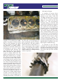
SPRING 2013 • ISSUE 79
Stag Engine Rebuild - Part 1
TOP END RECONDITIONING
by Tony Fox
Quite often, the reason for a Stag
engine rebuild is overheating and blown
head gaskets more than simply wear out
and old age. Triumph Stags as well as
TR 7s when subjected to an overheated
cooling system often suffer blown head
gaskets. They are not alone as many
engines with aluminum heads suffer
the same result when overheated due to
differential expansion of the aluminum
head and iron blocks. The overheating
and blown gasket quite often causes
warping of the cylinder heads and
subsequently necessitates some serious
repairs. These engines may be more
vulnerable than most as the water pump
sits high in the system and, a small loss
of coolant can leave it running dry,
but probably by that time it’s too late
anyway.
HEAD REMOVAL
First off, obviously you need to
remove the heads. “Easy you say, done
that many times”. Stag and TR7 heads
(as in old Jaguars) are notorious for
seizing on the studs. This is a major
problem if indeed they are stuck (and
most are) because the force required to
remove them is considerable. The heads
are retained by a row of bolts (relatively
short) which invariably come out easily.
In addition to these, there is a row of
longer studs which are angled to the
block face. They were designed on an
angle to allow simpler maintenance; you
could tighten the nuts without removing
the valve cover. The studs and head
fuse together due to corrosion inside the
drilled holes in the heads and are often
well and truly stuck. Usually, in this
instance, trying to remove the studs by
the normal extractor method ends up
shearing off the end of the stud. So now
10
you have a seized stud and the end of it
is now sheared off flush with the head. I
had one that I tried every known trick to
remove, soaked the studs in penetrating
oil and diesel oil for a year. Even
swinging at it in a very unprofessional
manner with a sledgehammer, it still
would not budge. A local experienced
engine shop suggested shocking the
studs with an electric welder. Sitting on
the tailgate of my truck all that did was
start a fire around the tailgate but the
head would not budge I’ve tried welding
nuts to the end of the stud and then using
an impact gun, you can shear the ends
off before any movement. Some users
have had success with the ‘rope trick’
which is to stuff rope into the cylinder
and then crank the engine compressing
the rope and pushing up on the head,
this has limited success and does not
work in most cases. When the heads are
eventually off you will find it necessary
to press out the studs, that’s how tight
they are stuck.
Talking to the man with the most
experience on Stag engines in the UK,
Tony Hart (always helps to speak with
those who know) he recommended
forcing one head off against the other,
said this is the only way and it will work.
I had previously thought of pushing on
the heads with a counteracting force on
the crankshaft but was concerned about
damage to the crankshaft and bearing
caps. His advice was to loosen one head
as far as possible and then push against
the other which was still bolted down.
This worked a treat, off came the head
in no time at all, after all the struggling
it was solved. When the first one is loose,
you reverse the procedure and refit it and
loosen the second head.
HEAD CONDITION, IS IT SAVABLE?
If the joint faces of the heads look
OK and there is no apparent warping,
remove the cam follower buckets and
tighten the heads down. Install the
camshafts and see if they are free to
turn, you should be able to turn them
comfortably by hand which indicates
and confirms if there is any warping.
In addition, when you get the heads on
the bench. run a straight edge across
them and see if there is any visible
distortion. Remember, if you machine a
warped head then the camshaft bores are
probably out of line too so will need line
boring or alternatively, have the head
straightened before machining.
Often heads have been machined on
previous occasions, so where is the limit
you ask? There is a dimension provided
by British Leyland but that barely gets
you past the first skim. The general
rule of thumb that has been adopted is
that when you skim the head, does the
cutter touch the inlet valve? If it does
not, you can happily rebuild the engine
using standard head gaskets. If you
consider machining isn’t needed as the
faces are simply too good, you can do
a check of the head thickness by laying
a straight edge across the face. If the
inlet valves are at or below the straight
edge then you can use a standard gasket
for the rebuild. If the inlet valve edge
stands above the face you must use a
thicker gasket. What you have to know
is that heads being machined down
causes the valves to get very close to
the pistons and contact can be made
particularly on the high compression
engines of European specification. The
North American specification engines
had a low compression piston with a
bowl in the piston crown so had a little
SPRING 2013 • ISSUE 79
more clearance. In addition, removing
material from the heads brings them
closer to the crankshaft, which retards
the valve timing slightly. As the
combustion chamber slopes up to the
head face, where the slope reaches the
machined head face you will find a small
step, on a new head this step is about
0.060ins high.
When you consider the head ready
for assembly, examine the head to
block face and make sure the area that
will be the gasket ‘fire ring’ seal area
is absolutely free of scratches or faults.
You can suffer abnormalities on other
areas but not in this critical region, it
could lead to a blown gasket. Remember,
these heads are aluminum and can get
damaged on this face quite easily so
handle with care.
Now, if the valve head outer lip is
proud of the head face, a solution has
been developed, again by Tony Hart in
the UK. Many years ago he developed a
gasket with an extra 0.20 ins thickness
added. If that fails to satisfy your needs,
you can also get a ‘head saver steel shim’
which picks up a further 0.020 ins.
So, having saved the head by
machining the face, where do we go
next? There are a few other important
considerations: the camshaft bearings in
the heads often get scored, particularly
the rearmost ones. This may require the
bearings to be line bored to clean up
the surface or better still have a bearing
insert added. Unfortunately, these are
not available as repair kits. However,
Stag Parts USA can have these repaired
for you. Also, it is quite common to find
some of the threads in the aluminum
in poor condition if not completely
stripped. It is far better to bite the bullet
and rethread ALL the threads in the
soft aluminum with a Helicoil insert or
similar, they do a good job of restoring
poor threads. This even extends to the
spark plug thread as I’ve known one
blow out of the head, so don’t take a
chance, restore the threads. It is not a
satisfying feeling to put the heads and
inlet manifold all back together and have
the last bolt go soft on you as the thread
strips, so make sure they are good before
you get that far. It is quite difficult to
add Helicoil inserts (some impossible)
with the heads in place in the engine
bay. So, do it before assembly into the
car. Remember, some of these heads are
40 years old by now and have seen a lot
of service and repairs in that time. Not
all mechanics over the years have been
sympathetic to these engines.
you have a manifold which doesn’t fit
good heads if you should have to change
them down the road. Another factor is,
the raised manifold causes some of the
coolant passages to be out of line, not
desirable. So, it is important to get the
heads around the original height with
the correct gaskets and shims or replace
the heads with better ones. In addition,
higher compressions will have you
looking for and paying for high-octane
gas.
While the heads are off why not
install harder valves that are suitable for
unleaded fuel. I’ve never heard of a valve
problem with these heads but as you are
fitting new valves anyway get the harder
ones which are readily available. Besides
which, the old valves and seats have, we
are told, a ‘lead memory’ from years of
use with leaded gas. The new ones you
just installed of course do not have this
characteristic.
Make sure the valve springs have
the steel collar under them where they
sit on the head, without these rapid wear
of the aluminum will occur (it has been
known).
The camshafts are usually OK,
maybe a slight scoring on the bearing
journals but are probably OK.
I like to balance the combustion
chambers, all eight of them. This makes
for a much smoother running engine.
Get the chambers within a 1.0 cc spread
for best results. If you have to use a
thick gasket one side and not the other
you need to compensate for this when
balancing the chambers, probably easier
to get both heads the same dimension to
avoid this.
If the head has had significant
machining to the joint face bringing
it lower to the engine block, this has
the effect of retarding the valve timing
and raising the compression ratio, both
of which are unwanted. Raising the
compression ratio can cause pinging
and extra stress on the head gasket
accompanied by potential overheating.
The retarded valve timing will cost
you a small amount of power, again
unwanted. The inlet manifold may
need facing off to compensate or the
holes to the head won’t line up. Then
When you come to reassemble the
heads on the engine, use some ‘Never
Seize’ compound on the head studs,
Copper Slip or other such product, you
will never have a stuck head again. Of
course, that is academic, as after your
rebuild the heads will never need to
come off again.
It is a good idea to use new studs
and nuts too as you don’t know if the
old ones have been stretched and are
probably corroded. Use the correct
hardened washers under the nuts too.
Check the cam followers for wear on
the cam lobe follower contact face, look
for breakdown of the hardened surface
and pitting of the followers which if
present means the case hardened surface
has been compromised. Examine
carefully the bores for the followers in
the head, it is common to have wear
ridges at the bottom of the bores at
the limit of the followers travel. With
different adjustment of the valve
settings these ridges will often cause a
ticking noise that sounds like the valve
clearances are incorrect but in fact
it is the cam follower bucket hitting
this ridge. Incidentally, oversize cam
follower buckets are available should
your bores be in worn condition.
Continued next issue...
11
SUMMER 2013 • ISSUE 80
Stag Engine Rebuild - Part 2
TOP END RECONDITIONING
by Tony Fox
Continued from last issue...
Tightening the heads on these
engines is an u nconventional
pattern so read the official British
Leyland service manual for the
correct procedure. You tighten
the top row first starting from
the middle and working evenly
outwards followed by the bottom
row. This is most critical. Retorquing must be done with a
cold engine, so r un it up after
the f i rst i nst allation and get
hot but leave overnight to cool
down before attempting the retorque. Keep re-torquing until no
further movement is found. Later
attempts to re-torque should be
made by backing off each nut in
turn a fraction before applying the
torque wrench; this eliminates any
stiction of the threads.
Millennium heads
If you are absolutely desperate
for heads, Mike Fisher of the Stag
Owners Club Tooling Fund in the
UK has engineered new heads,
quite a project. These are brand
new heads named Millennium
Heads. They are quite expensive
but make a nice job for the engine.
They are not changed from the
original design and material but
an exact reproduction made by
reverse engineering the drawings.
Should you get into replacing
a head(s) be aware that MK 1
and MK 2 heads differ from each
other. You should not mix the
heads on a given block and piston
configuration. MK 2 heads can be
used on a MK 1 engine but with
the result of a lower compression,
not desirable. You should however
never use MK 1 heads on MK 2
engines and there is insufficient
valve to piston clearance if the
engine has the high compression
domed pistons. The heads can be
easily identified by a number cast
into the surface just below the
spark plug holes, MK 1 numbers
are identified as 3142 RH, 3143 LH
and MK 2 as 3242 RH and 3243
LH.
Water pump overhaul
Now you h ave t h e i n le t
manifold off you have exposed
the water pump so might just as
well overhaul this. The pump is
only accessible with the manifold
removed (another brilliant design).
Worn pump gears could be the
initial cause of the overheating so
it is important to do this. There
are some things to be cautious
about though. For one thing, I
recommend NOT fitting a new
pu mp but rebuildi ng t he old
one. I say this as there are some
dodgy pumps out there that have
both very poor case hardening
a nd mach i ned a ngles on t he
gear that are sometimes out of
specification. Either one of these
conditions will cause premature
wear of the jackshaft gear to a
point where it fails. Once this
gear fails the coolant circulation
stops and overheating begins,
sound familiar? Now you have an
even more serious problem as not
only has the engine overheated
again but also it has distributed
a ha ndf ul of met al shav i ngs
evenly around the engine and
crankshaft bearings. On a good
note, most likely the old gear will
be OK unless it has been changed
recently. The original gears from
the factory last for many thousands
of miles, in fact I’ve not seen a
seriously worn gear on an original
pump. Usually you will find just
a nice meshing patter n with a
narrow line of contact which is
what you want to see. (See my
article on water pumps in issue
April 2007)
To remove the pump, f irst
remove the single bolt which holds
the impellor in place. Be aware,
this bolt is left hand thread. I have
made up a special bolt to replace
this, which allows me to attach an
impact puller to jerk the pump out
of the block. Quite often the pump
innards will come out leaving the
brass cage in the block, this must
be removed too. Rebuild kits can
be purchased to overhaul the pump
consisting of a new bearing and
all the seals you need. Replace the
lower bearing in the block where
the end of the pump shaft locates.
Test fit the new seal pack in the
brass cage before proceeding, they
have been known to be slightly
oversize.
Make sure the bore in the block
will accept the pump brass cage
smoothly before you start as you
do not want to be hammering the
thing back in place. When you are
ready to put the pump back in you
can wind the pump back in place
against the helical drive gear using
the left hand thread bolt on the
5
SUMMER 2013 • ISSUE 80
Alternative designs
impellor. You could tap in VERY
gently if you have to but too hard
and you will damage the gland
of the ceramic seal pack under
the impellor, it is quite brittle.
Follow the workshop manual for
shimming the top cover which
is straightforward. Measure the
gap between the cover and the
block and add the shim gaskets
to give a further 0.020 ins. The
gaskets provided come in several
different thicknesses to permit
this. There are two pumps around,
6 vane and 12 vane. They can be
interchanged on the engine so long
as you change the top outlet cover
too. These are quite different and
getting the wrong one on there will
cause a problem. The 12 vane is
preferred by some builders but then
others like the 6 vane, so ‘you pays
your penny and takes your choice’.
From the performance curves I’ve
seen, for everyday driving the 12
vane gives a slight improvement
in f low. I know that Tony Hart
prefers the 6 vane for high speed
running and racing. LD Parts in
6
the UK sell a revised design seal
pack commonly used by Perkins
diesel engines, LD part number
148322. It can be used either as a
direct replacement of the original
seal or, by machining the impeller
slightly, a ceramic mating surface
can be added, no rusting rotating
surfaces any more.
A nu mber of ow ners have
turned to an electric water pump
desig n to get away f rom the
Triumph designed gear driven
type. Davies, Craig of Australia
makes a ver y nice kit for this
( EW P 115). T he me cha n ical
Triumph pump is removed and
replaced by a solid plug to separate
the coolant from the oil gallery,
you could leave the old pump in
but then you have the restriction
of the impellor to contend with.
The electric pump will constantly
pulse coolant until it senses a pre
set temperature at which point the
f low will increase until full f low
is required. Users report a more
steady temperature control. You
do need a supplemental pump to
feed the heater though as in a cold
ambient there is going to be very
little engine coolant flowing.
A company in the UK has
available an externally mounted
mechanical pump that requires the
alternator to be relocated, a simple
conversion that provides reliable
service.