1
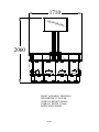
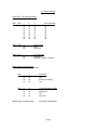
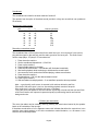
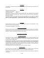
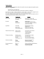
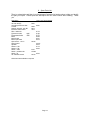
OPERATING and
SERVICE GUIDE
Produced by ;
Harry Levy Amusement Contractor Ltd
Unit 6 Patricia Way
Pysons Road Industrial Estate
Broadstairs
Kent
CT10 2LF
Tel (+44) 01843 866 464
Fax (+44) 01843 860 144
Overall Weight
Kg
lbs
370
816
Issued 18th December 2001
CONTENTS
Section 1 – Contents
1.1 Cabinet Drawing
Section 2 - General Information
Section 3 - Commissioning
3.1 Maintenance
3.2 Receiving your machine
3.3 Self test
3.4 Tilt
3.5 Preparing the machine
3.6 Normal play
Section 4 - Special Features
4.1 Tilt & diverter system
4.2 Motor Control Board
4.4 Counters
Section 5 - Access
5.1 General
5.2 Playfield
5.3 Lower cabinet
5.4 cashbox compartments
5.5 Top sign
Section 6 - Electrical system
6.1 Fuses
6.2 Switch settings
6.3 Motor Jam reset switch
6.4 Speaker
6.5 Lighting
6.6 Counters
6.7 Logic & control boards
Section 7 - Mechanical systems
7.1 Pusher motor drive
7.2 Pushers
7.3 Coin entry chutes
7.4 Diverter
Section 8 - Fault finding
Section 9 - Spare parts List
Page 2
1710
HIPP
ODR
OM
E
2060
FRONT ASSEMBLY DRAWING
HIPPODROME 12 PLAYER
OVERALL HEIGHT 2060mm
OVERALL WIDTH 1710mm
DODECAGON SHAPE
Page 3
2. GENERAL INFORMATION
This Manual is intended as a guide to servicing, fault finding and repairs on your Hippodrome
pusher.
All details and specifications shown in this manual were correct at the time of print. The right to
modify equipment, change specifications and instructions at any time, without notice is reserved as
part of Harry Levy Amusement Contractor Ltd. policy of continuous development and improvement.
Only qualified, professional personnel should gain entry to the machine, and no liability is accepted
by Harry Levy Amusement Contractor Ltd. or their staff for any damage or injury arising from the
use of this service manual.
3. Commissioning.
3.1 Maintenance
To keep your machine in optimum condition for maximum profit, maintain all visible internal and
external surfaces in a clean 'as new' condition.
·
·
1 Laminated cabinet body - Clean with an all purpose cleaner.
2 Glass and chrome parts - Clean with a quality window cleaning solution.
Always use cleaning products according to the manufacturers own instructions.
3.2 When you receive your machine.
Remove any transit packing materials from the machine then site your pusher on a smooth level
floor. Please handle your machine with care using appropriate lifting equipment, do not drop or
subject it to shocks, or a damp environment. Connect to the mains using the lead supplied.
Important - This machine must be grounded (earthed).
3.3 Switch On and Self Test.
Switch the machine ON. All the fluorescent lamps will light and the pusher boxes will start moving.
The alarm will not sound. The diverter solenoids will not operate.
At intervals the attract sounds will operate. Adjust the volume level to suit the surroundings.
The volume control is situated on the sound card on the left hand wall inside section 2, to the right
of section 1, where the mains lead enters.
3.4 Tilt.
There are tilt sensors on each paycup door and within the topsign. Bumping the machine will
sound the alarm bell, switch off the playfield lights and divert all coins that fall from the playfields
into the internal cash-boxes. This state will continue for approximately 5 seconds, then the
machine reverts to its normal play mode.
3.5 Preparing the Machine.
After checking the machine functions correctly each playfield will require approximately 300 coins
to float or prime it ready for play. The first 90% of the coins may be hand placed in small batches
onto the moving pusher box, allowing the machine to spread them onto the main playfield. The
final 10% of coins (and winnings) should be played into the machine through the coin entries.
Page 4
3.6 Normal Play.
When a player inserts a coin it passes a sensor that switches that section on, enabling the playfield
winnings system to make legitimate awards. The section remains enabled for approximately 30
seconds. A coin counter records each coin inserted.
If tilted or bumped whilst being played the tilt system takes over the entire machine. Coins falling
from the playfield are routed to the cashbox.
When a section is not being played, any coins falling from the playfield are routed to the cashbox.
4. Special features
4.1
Tilt & diverter system
There are two tilt & diverter boards, each controlling six sections, located in the lower cabinet.
These monitor the coin entries and control the diverter solenoids individually. They also constantly
monitor the tilt alarms, which over-ride the normal game functions. There is a bank of dip-switches
on each board. See switch settings.
4.2
Motor controller board.
The pusher box motor is controlled and driven by a control board. This is located in the power
supply box inside section 5. If the motor should jam for any reason, the motor will stop and the
alarm will sound. Clear the jam and push the reset button to restart. The reset button is recessed in
the underside of the top sign. There is a bank of dip-switches to vary the sensitivity of the system
and an override facility (See switch settings).
4.3
Counters.
There is a single counter per section to count coins-in, located inside the paycup door.
5. ACCESS.
5.1 General
With the exception of external cleaning always disconnect the machine from the mains supply by
removing it's plug from the supply socket.
5.2 Playfield.
Release the locks on the glass window and lift it carefully out of the machine. Place the glass
somewhere safe for temporary storage.
5.3 Lower Cabinet.
Each player section has an access door below the playfield which can be fully removed by
releasing the locks at the top of the door.
This gives access to the following:lose coin chutes
win coin chute
diverter solenoid
paycup
pusher motor and drive system
power supply units including reset fuses.
Sound Board
Page 5
5.4 Cash box compartments.
Each player section has an access door below the pay-cup which can be fully removed by
releasing the lock at the top, and lifting the door out. This gives access to a lockable cashbox.
5.5 Topsign.
To gain entry to the topsign, disconnect the machine from the mains supply.
There is an access panel on the topsign roof held by 4 screws. If possible, pereform all
maintenance through here as removal of the artwork can be difficult to put back together.
If necessary, the artwork can be removed by releasing the 3 bolts on the topsign roof. The roof
panel then lifts and the artwork can be sprung out. Do not lose the join overlap pieces.
Inside the topsign are the fluorescent lights and associated gear trays and relay board. Other
equipment includes:Top feed mains entry point
Alarm sounder
Pendulum tilt
Speakers
Central column lamp flasher board.
6. ELECTRICAL SYSTEMS.
The mains inlet plug is recessed in the base of the machine. There is also a top feed facility on the
top of the machine. Both are fitted with a 5 Amp filter.
The mains switch is located in section 1, directly above the mains inlet plug.
The mains wiring is all double insulated in the cabinet base. The motor is shrouded in an earthed
metal box. The topsign wiring is only singly insulated. Disconnect the machine from the mains
supply before attempting to gain entry to the topsign.
6.1 Fuses
The mains switch housing incorporates a 5 Amp reset type fuse.
The power supply boxes also incorporate reset type fuses of various values to protect the various
low voltage wiring and systems from excess current. See wiring diagrams for details.
The mains fuse for the drive motor is fitted on the motor drive board in the power supply box inside
section 5:
Mains Motor fuse - 2 Amp(T) (Time delay)
Each diverter solenoid has a reset fuse fitted as part of its assembly:
24V Diverter Solenoid supply - 1.5 Amp reset - 1 per section
Page 6
6.2 Switch Settings
Game time:- Tilt & diverter board
Program
TDIV11 V1.0
SW1
Pole
1
off
on
off
on
off
on
off
on
2
off
off
on
on
off
off
on
on
3
off
off
off
off
on
on
on
on
time (seconds)
3
20
30
40
50
60
75
90
SW1
Pole
4
off
on
Power up tilt
none
20 sec tilt
SW1
Pole
7
off
on
Coin Counters
individual
common (section 1 counter)
Motor speed controller board.
This board has a bank of 4 switches.
pole
1
off
on
off
on
2
off
off
on
on
sensitivity
very high
high
normal run setting
low
pole
3
off
on
off
on
4
off
off
on
on
motor resistance to stall
normal
slightly low
low
very low
Special case override setting:-
All 4 poles switched ON.
Page 7
Soundboard
The soundboard is located in the lower cabinet of section 2.
The operator has the option of the attract sound provided, or they can record their own (maximum
55 seconds).
Attract music timer interval:pole
1
off
on
off
on
off
on
off
on
2
off
off
on
on
off
off
on
on
3
off
off
off
off
on
on
on
on
interval / seconds
music off
30
60
90
120
150
180
210
Recording a new attract sound
The soundboard has a 3.5mm jack socket for an audio line input – this requires a 2 pole (mono)
plug with the signal on the end pole, and the audio ground on the inner pole. The audio source
can be a tape player, CD player, PC soundcard etc.
1. Power down the machine
2. Set the soundboard dipswitches 1,2,3 all ON
3. Power up the machine
4. Prepare audio source for playback
5. Press the RECORD button – red indicator will illuminate immediately
6. Start audio playback whilst continuing to hold down the record button
7. As soon as the audio section has finished playing, release record button
8. Power down the machine
9. Set dipswitches 1,2 & 3 for the desired attract interval
10. Power up the machine
11. Wait until attract sound plays back – if not satisfied, repeat the above procedure.
Note – a good quality audio source is essential, with minimum distortion and hiss.
If the level of the audio input is too low, the resulting playback sound will be quiet.
If the audio level is too high, distortion will occur on playback
Timing the press and release of the record button to precisely coincide with the start and finish
of the sound section will improve the perceived quality by eliminating lead-in and lead-out
background noise.
6.3 Motor jam reset switch.
The motor jam alarm can be manually reset by pressing the reset button located by the speaker
bezel on the underside of the top-sign.
If the alarm sounds often or for no apparent reason this indicates that either the motor driver is too
sensitive (see switch settings), or the drive mechanism needs lubrication, or a tilt sensor is too
sensitive and needs adjustment.
Page 8
6.4 Speaker.
If the speaker is suspected faulty it should be replaced with one of the same type and rating, use 8
Ohm 25 Watt.
6.5 Lighting.
Fluorescent tubes are situated :a) Between every playfield. - 13W x 12
b) Inside the top sign.
- 18W x 3
Replacement is carried out with the machine switched OFF, then releasing the end caps and
removing the tube from the spring clips. Insert a new tube of the correct type and rating and reconnect the end caps.
The lighting starters on the light boards are also consumable items and should be checked
whenever a lamp appears defective. Starters have different rating to suit the lamp, and different
types to suit the wiring configuration. Always replace a starter with an exact equivalent type.
6.6 Counters
Electro-mechanical counters are included to enable you to monitor the performance of your
pusher, and check the cash accounting.
Counters are incorporated for coins-in only.
6.7 Logic & control boards
These are custom made to perform the functions necessary for correct operation of the machine.
In general they are not user serviceable and should a fault arise they should be sent back to your
distributor or Harry Levy Amusement Contractor Ltd for repair.
7. MECHANICAL SYSTEMS.
7.1 Pusher motor drive.
The main drive motor is situated beneath the playfield. There are mechanical linkages to the
moving boxes. As long as the slide bearings are kept clean and lightly greased the system will
give many years of reliable service.
A fail-safe cut-out is included on the motor to protect it from stall conditions. The motor shaft speed
is monitored by a rotation opto sensor. If the system suffers a mechanical jam the reduced speed
will be detected and the supply to the motor will be turned off. The alarm will sound. Switch the
machine off, remove the cause of the jam and switch the machine on again. If the jam self cleared,
pressing the reset button will re-start the motor.
The sensitivity of the monitoring system can be varied. See Switch Settings.
7.2 Pusher boxes.
The pusher boxes are mounted on two Accuride slide bearings. An annual check to remove any
build up of dust, and a light coat of grease will ensure many years of reliable service.
Ensure that the coin scraper system is fully intact and working smoothly and freely, replace any
suspect parts.
Page 9
7.3 Coin entry Chutes.
Each player section has two coin entry chutes. The chutes are fitted with flag opto sensors to
detect coins. Other than keeping the chutes clear and clean no maintenance is required.
7.4 Diverters.
Each player section has a coin diverter located between the playfield and the paycup & cashbox.
The default state is to route all coins to the cashbox, this occurs when ;·
·
·
The machine is switched off.
The machine is on but that section is not being played.
The machine is in Tilt mode.
The only time the diverter allows coins into the paycup is when a legitimate game has won coins
from the playfield.
Note - Each player section works independently of the other sections.
If a fault is suspected first check for mechanical jams (a coin stuck), and smooth operation of the
diverter flap, then check the fuses and power to the solenoid. Rectify as appropriate.
8. Fault finding
It is of mutual interest that your pusher is kept in excellent working condition, therefore when
required please order original replacement parts from your distributor or Harry Levy Amusement
Contractor Ltd.
If a fault occurs with any electrical system: SWITCH THE MACHINE OFF. Check that :a) There is a suitable mains supply.
b) All reset fuses are intact (they pop out if overloaded, push to reset).
c) All plugs and sockets are correctly mated.
d) No wires are trapped, damaged or broken.
e) All wires are properly secured to their terminals and pins.
Wiring check.
A visual inspection will reveal the general condition of the wiring. A more thorough test using a
continuity tester will be needed to check apparently intact wires, however once a machine has
been playing successfully for some time wiring is not usually at fault.
Device testing.
Disconnect the machine from the mains supply then check the physical condition and operation of
the suspect device (remove from the machine if necessary). Bench test if possible using a suitable
power supply.
In general PCB's are not user serviceable. Should a problem develop indicating a board fault it is
recommended that the board is returned for repair by your distributor.
Fault diagnosis and repair may be performed by skilled service personnel, but this may invalidate
the warranty.
Page 10
Systems checking.
When a fault occurs that affects the whole of the machine, the power supply and regulation system
should be investigated first.
Check the input, and output fuses.
Refer to schematics and drawings to check power connections, voltages etc.
If the fault is not visual, or easily measurable it is often helpful to disconnect the outputs from the
PSU, check that the PSU is functioning then connect the loads one at a time.
It is easy to identify the faulty system, then use a similar technique within that system (such as
disconnecting all solenoids) to identify the faulty component.
Symptom
Possible Fault
Remedy
Will not start
Mains switch OFF
Fuse blown
Check mains switch is ON
Check plug fuse then internal fuses.
No sound
Volume
Speaker
Sound board
Adjust volume
Check wiring. Replace if faulty
Check power supply & connectors,
replace board if faulty.
Light failed
Tube failed
Check end caps & wiring
Replace tube.
Replace with same type.
Replace with same rating.
Starter failed
Choke (ballast) failed
Pusher boxes not moving
Power to motor
Mechanical jam
Check power & connections.
Check for coins or
swag causing jam.
Clear & reset.
Tilt alarm not working
Pendulum stuck
Door bump sensor
Sounder
Tilt & diverter P.C.B
Check pendulum & adjust.
Check & adjust.
Test connections & power
Check connections & power.
Counter not working
Wiring
Counter
Opto sensor
Check connectors & loom
Bench test / replace.
Check every opto sensor.
Diverter solenoid not
working.
Burnt out.
Power.
Jammed.
Measure resistance(100-500 Ohms).
Check 24V DC supply.
Check for obstruction.
Page 11
9. Spare Parts List
There is a description and Harry Levy Amusement Contractor Ltd stock number to help you identify
the part you require. Please quote the description and our stock number when ordering. Thank
you.
Description
201 lock & keys
301 lock & keys
Accuride pusher box slide
Counter
Diverter solenoid - 24V DC
Electronic alarm board
Filter - Mains 5A
Fluorescent tube
18W
Fluorescent tube
Motor
Motor board
Motor opto board
Opto sensor - coin in
Sound board
Speaker
Starter - FSU
Starter - FS2
Switch - reset
Switch - pendulum tilt
Switch - tilt
Tilt & Diverter board
Harry Levy Stock Number
6278
6087
6081
6029
8912
7819
8179
6126
15W
6151
8309
8321
8318
22129
22167
6979
6119
6042
6127
CC004
6534
22143
Other items are available on request.
Page 12