1
Installation and maintenance instructions
For the competent person
Installation and maintenance instructions
ecoTEC plus
VUI
GB, IE
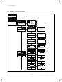
Table of Contents
i
BEFORE PROCEEDING - ENSURE BOILER IS
CORRECT FOR GAS GROUP SUPPLIED!
Table of Contents
1
1.1
1.2
1.3
1.4
1.5
1.6
1.7
Notes on the documentation .....................................5
Storing documents ..........................................................5
Symbols used ....................................................................5
Applicability of the instructions ...................................5
Identification plate...........................................................5
CE label...............................................................................5
Benchmark.........................................................................6
Type overview ...................................................................6
2
2.1
2.1.1
2.1.2
2.2
2.3
2.4
2.5
2.5.1
2.5.2
2.5.3
2.5.4
2.5.5
2.5.6
2.5.7
2.5.8
2.5.9
2.5.10
Safety ................................................................................. 7
Safety and warning information .................................. 7
Classification of warnings .............................................. 7
Structure of warnings ..................................................... 7
Intended use...................................................................... 7
Basic safety instructions ................................................ 7
Important information regarding
propane-fired boilers.......................................................8
General requirements .....................................................9
Related documents ..........................................................9
Installation site .................................................................9
Gas supply ....................................................................... 10
Air supply ......................................................................... 10
Compartment ventilation ............................................. 10
Electrical supply ............................................................. 10
Water supply Combination boilers............................. 10
Water circulation system.............................................. 10
Pressure relief valve........................................................11
Venting ...............................................................................11
3
Description of the unit ................................................12
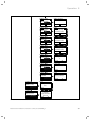
4
4.1
4.1.1
4.1.2
4.2
4.2.1
4.2.2
4.2.3
4.2.4
4.3
4.4
4.4.1
Installation ......................................................................13
Accessories .......................................................................13
Controller ..........................................................................13
Installation and operation.............................................13
Scope of delivery ............................................................13
Unpack the layered storage tank ................................13
Unpacking the boiler ......................................................13
Checking the scope of delivery....................................13
Disposing of the packaging ..........................................14
Transporting the appliance ..........................................14
Requirements for the installation site .......................17
Required minimum clearances/
installation clearances ...................................................17
Using installation templates .........................................17
Dimension drawing and connection dimensions .... 18
Wall-mounting the layered storage tank ................ 20
Wall-mounting the boiler............................................. 20
Removing/fitting the front casing ..............................21
Removing/fitting the side panel ..................................21
4.4.2
4.5
4.6
4.7
4.8
4.9
2
5
5.1
5.2
Gas installation .............................................................22
Preparing for installation .............................................22
Connecting the gas line................................................22
6
6.1
6.2
6.3
Hydraulic installation .................................................23
Preparing for installation .............................................23
Connecting the hot and cold water ..........................24
Connecting pipe connections between the
layered storage tank and the boiler ..........................24
Connecting the heating flow and heating return...24
Low loss header .............................................................24
Connecting the condensate discharge pipework ...25
Connecting the discharge pipe to the expansion
relief valve on the boiler ..............................................26
Connecting the discharge hose to the expansion
relief valve on the layered storage tank ..................26
6.4
6.5
6.6
6.7
6.8
7
7.1
7.2
Flue gas installation ...................................................27
Air/flue gas duct.............................................................27
Flue termination .............................................................28
8
8.1
8.2
8.3
8.8
Electrical installation ................................................ 30
Preparing for installation ............................................ 30
Opening/closing the electronics box ........................ 30
Connecting the layered storage tank to the
power supply ....................................................................31
Establishing the mains connection ............................32
Connecting the controller ............................................33
Fitting the controller .....................................................33
Connecting controllers to the electronic system ...33
Connecting additional components ........................ 34
Connecting an auxiliary relay (grey plug on
the PCB) .......................................................................... 34
Connecting a VR 40 – "2 from 7" multi-functional
module ............................................................................. 34
Actuating the circulation pump
demand-controlled........................................................ 34
Connection diagrams ....................................................35
9
9.1
9.2
Operation ........................................................................37
Calling up the installer level ........................................37
Overview of the menu structure ............................... 38
10
10.1
10.2
10.2.1
10.2.2
10.2.3
10.2.4
10.2.5
10.2.6
10.2.7
10.2.8
10.2.9
10.2.10
10.2.11
10.3
10.4
Commissioning ............................................................. 40
Switching on the boiler................................................ 40
Installation assistant .................................................... 40
Language ........................................................................ 40
Filling mode .................................................................... 40
Purging ............................................................................ 40
Target feed temperature ...............................................41
Hot water temperature ..................................................41
Comfort mode ..................................................................41
Heating partial load........................................................41
Auxiliary relay and multi-functional module............41
Competent person telephone number.......................41
Terminating the installation assistant .......................41
Restarting the installation assistant ..........................41
Appliance configuration and diagnostics menu ......41
Using test programs .......................................................41
8.4
8.5
8.5.1
8.5.2
8.6
8.6.1
8.6.2
8.7
Installation and maintenance instructions ecoTEC plus 0020134833_01
Table of Contents
10.5
10.6
10.7
10.7.1
10.7.2
10.7.3
10.8
10.9
10.10
10.11
10.12
10.12.1
10.12.2
10.12.3
10.12.4
10.13
10.13.1
10.13.2
10.13.3
10.14
11
11.1
11.1.1
11.1.2
11.1.3
11.1.4
11.1.5
11.1.6
11.1.7
11.1.8
11.2
12
12.1
12.1.1
12.1.2
12.1.3
12.1.4
12.1.5
12.2
12.2.1
12.2.2
12.2.3
12.3
12.3.1
12.4
12.4.1
12.4.2
12.4.3
12.4.4
12.4.5
12.4.6
Preparing the heating water ...................................... 42
Reading off the filling pressure ................................. 42
Filling and purging the heating installation ........... 42
Filling the heating installation ................................... 43
Purging the heating installation................................ 43
Flushing the system for the first time ("cold") ..... 44
Avoiding low water pressure ...................................... 44
Topping up the VUI boiler using a filling device .. 44
Fill and purge the hot water system ........................ 44
Filling the condensate siphon .................................... 45
Checking the gas ratio setting................................... 45
Factory setting ............................................................... 45
Checking for tightness of the flue gas
installation and flue gas recirculation ..................... 46
Checking the gas flow rate ......................................47
Checking the gas inlet working pressure .................47
Carrying out a full function test................................ 48
Checking the heating mode ....................................... 49
Checking the hot water generation.......................... 49
Checking the cylinder charging................................. 49
Final flush of the heating system ("hot") ............... 50
Adapting the boiler to the heating installation 50
Diagnostics codes – Overview .................................... 50
Setting the heating partial load ................................ 54
Setting pump overrun time and pump
operating mode ............................................................. 54
Setting the maximum flow temperature ................. 55
Setting the return flow temperature control ......... 55
Burner anti-cycling time.............................................. 55
Setting the maintenance interval ............................. 56
Setting the pump output............................................. 56
Setting the bypass valve ............................................. 56
Handing over the boiler to the operator..................57
Inspection and maintenance ................................... 58
Inspection and maintenance intervals ..................... 58
General inspection and maintenance
instructions..................................................................... 59
Safety instructions ....................................................... 59
Checking the CO/CO2 ratio and the CO2
concentration ................................................................. 59
Adjusting the CO2 concentration
(or the air ratio) ............................................................. 60
Performing the gas family check ................................61
Inspection and maintenance work steps..................62
Filling the boiler and the heating installation .........63
Draining the boiler .........................................................63
Draining the entire heating installation ...................63
Using the function menu .............................................63
Carrying out electronics self-tests ............................63
Carrying out maintenance work.................................63
Removing the compact thermal module..................63
Cleaning the heat exchanger ..................................... 65
Checking the burner .................................................... 65
Cleaning the condensate siphon ............................... 66
Cleaning the filter in the cold water inlet ............... 66
Installing the compact thermal module ...................67
Installation and maintenance instructions ecoTEC plus 0020134833_01
12.4.7
12.4.8
12.5
12.5.1
13
13.1
13.2
13.2.1
13.2.2
13.2.3
13.2.4
13.2.5
13.2.6
13.2.7
13.2.8
13.3
13.4
13.5
14
14.1
14.1.1
14.1.2
14.2
14.3
14.4
14.5
Checking the pressure of the expansion vessel
on the boiler ................................................................... 68
Check the pressure of the expansion vessel
on the layered storage tank ....................................... 68
Checking the gas flow pressure ................................ 68
Checking the CO2 content........................................... 68
Troubleshooting ........................................................... 69
Contact Vaillant Service Solutions
(0870 6060 777) .......................................................... 69
Performing diagnostics ............................................... 69
Calling up Live Monitor (status codes) .................... 69
Status codes – Overview ............................................. 69
Service messages ..........................................................70
Calling up diagnostics levels .......................................70
Reading off the fault codes .........................................70
Querying the fault memory .........................................70
Resetting the fault memory ........................................70
Overview of fault codes.................................................71
Using the function menu .............................................73
Running test programs .................................................73
Resetting parameters to factory settings ................73
14.11.3
Replacing components ............................................... 74
Preparing for and completing replacement work .. 74
Preparing for replacement work ................................ 74
Completing replacement work.................................... 74
Replacing the burner .................................................... 74
Replacing the fan ...........................................................75
Replacing the gas valve................................................76
Replacing the Venturi including the mass flow
sensor ...............................................................................77
Replacing the expansion vessel..................................78
Replacing the heat exchanger ....................................78
Replacing the expansion vessel of the layered
storage tank ................................................................... 80
Replacing the cylinder charging pump on the
layered storage tank .................................................... 80
Replacing the impeller sensor on the layered
storage tank .................................................................... 81
Replacing the PCB and/or the display ...................... 81
Replacing either the display or the PCB on the
boiler ................................................................................ 82
Replacing the PCB and the display on the
boiler at the same time ............................................... 82
Replacing the PCB on the layered storage tank ... 83
15
15.1
15.2
15.3
Decommissioning ........................................................ 83
Temporarily shutting down the boiler ..................... 83
Taking the boiler permanently out of service ....... 83
Disposing of the boiler ................................................ 84
16
16.1
16.2
Guarantee and customer service........................... 84
Factory guarantee......................................................... 84
Vaillant Service .............................................................. 84
14.6
14.7
14.8
14.9
14.10
14.11
14.11.1
14.11.2
3
Table of Contents
17
Technical data .............................................................. 85
18
Glossary ..........................................................................87
19
Appendix ........................................................................ 88
20
Benchmark Log Book ................................................. 89
21
EC declaration of conformity ................................... 91
Index
............................................................................................92
4
Installation and maintenance instructions ecoTEC plus 0020134833_01
Notes on the documentation 1
1
Notes on the documentation
1.4
The following information is intended to help you throughout the entire documentation. Further documents apply in
combination with these installation and maintenance
instructions.
We accept no liability for any damage caused by failure to
observe these instructions.
Other applicable documents
> When installing the ecoTEC plus, follow all installation
instructions for the various parts and components of the
system without exception.
These installation instructions are enclosed with the various
system parts and supplementary components.
> Furthermore, observe all operating instructions enclosed
with components of the system.
1.1
Identification plate
The identification plate of the Vaillant ecoTEC plus is
attached to the underside of the boiler in the factory.
The article number of the gas-fired wall-hung boiler can be
found in the serial number. The seventh to sixteenth numbers constitute the article number.
The serial number can also be found on the lift out badge
located behind the front flap at the bottom of the boiler.
The serial number can also be shown on the display of the
boiler (Operating instructions).
1.5
CE label
The CE label shows that the boilers comply
with the basic requirements of the applicable
directives as stated on the identification plate.
Storing documents
> Pass these installation instructions and all other applicable documents and, if necessary, any required tools to
the system operator.
The system operator should retain these instructions and
tools so that they are available when required.
1.2
Symbols used
The symbols used in the text are explained below:
i
>
1.3
Symbol that denotes useful tips and information
Symbol for a required action
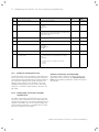
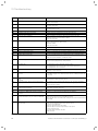
Applicability of the instructions
These installation instructions are only valid for boilers with
the following article numbers:
Boiler
Type designation
Article
number
Gas
Council
Number
ecoTEC plus
937 (VUI GB 376/5-5)
0010011689
47-044-43
– Directive 2009/142/EEC of the Commission with amendments "Directive for Harmonisation of Legal Regulations
of the Member States for Gas Consumption Appliances"
(Gas equipment directive)
– Directive 92/42/EEC of the Commission with amendments "Directive Concerning the Efficiency of New Hot
Water Heating Boilers Fired by Liquid or Gaseous Fuels"
(Efficiency directive)
– Directive 2006/95/EC of the Council with amendments
"Directive Concerning Electrical Equipment for Use
Within Specific Voltage Limits" (Low voltage directive)
– Directive 2004/108/EC of the Council with amendments
"Directive Concerning Electromagnetic Compatibility"
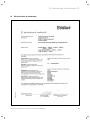
The boilers comply with the type sample described in the
EC Type testing certificate.
PIN no. CE-0085CM320
The boilers comply with the following standards:
– EN 483
– EN 625
– EN 677
– EN 55014
– EN 60335-1
– EN 60335-2-102
– EN 61000-3-2
– EN 61000-3-3
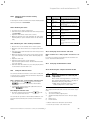
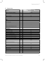
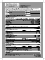
1.1 Unit types, article numbers and Gas Council Number
The article number of the boiler can be found on the identification plate.
Installation and maintenance instructions ecoTEC plus 0020134833_01
5
1 Notes on the documentation
1.6
Benchmark
Vaillant Ltd. supports the Benchmark Initiative.
You will find the Benchmark Logbook on the last pages of
this instruction manual. It is very important that this document be filled out properly when installing, commissioning,
and fully explained at hand over to the operator of the
installation. Installers should point out also the service
record section for completion following service calls to this
appliance.
Vaillant Ltd. is a licensed member of the Benchmark
Scheme which aims to improve the standards of installation
and commissioning of domestic heating and hot water systems in the UK and to encourage regular servicing to optimize safety, efficiency and performance. Benchmark is
managed and promoted by the Heating and Hot water
Industry Council.
> For more information visit www. centralheating .co .uk
i
6
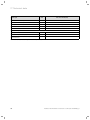
1.7
Type overview
Unit type
ecoTEC plus
Designated country
(designation in
Approval cateaccordance with ISO gory
3166)
937 (VUI GB 376/5-5)
GB (Great Britain)
IE (Ireland)
II2H3P
1.2 Type overview
Vaillant supply a special self adhesive sticker on
top of the boiler for use in entering the serial
number details straight onto the commissioning
checklist found in the last pages of this document.
Installation and maintenance instructions ecoTEC plus 0020134833_01
a
Safety 2
2
Safety
2.1
2.2
Safety and warning information
> When installing the ecoTEC plus, you must observe the
basic safety instructions and the warning notes that
appear before all of the actions.
2.1.1
Classification of warnings
The warnings are classified in accordance with the severity
of the possible danger using the following warning signs
and signal words:
Warning
symbol
Signal
word
a
e
a
b
Danger!
Explanation
Imminent danger to life or
risk of severe personal
injury
Danger!
Risk of death from electric
shock
Warning.
Risk of minor personal injury
Caution.
Risk of material or environmental damage
Intended use
The Vaillant ecoTEC plus boilers are constructed using
state-of-the-art technology in accordance with the recognised safety rules and regulations. Nevertheless, there is
still a risk of injury or death to the operator or others or of
damage to the boiler and other property in the event of
improper use or use for which it is not intended.
This boiler is not intended for use by persons (including
children) having limited physical, sensory or mental capacities or who have inadequate experience and/or knowledge,
unless supervised by a person responsible for their safety
or they have been instructed by him/her about how to use
the boiler.
Children must be supervised to ensure that they do not
play with the boiler.
The boiler is intended as a heater for closed central heating
installations and for hot water generation.
The use of the ecoTEC plus in vehicles, such as mobile
homes and caravans, is not classed as intended use. Units
that are not classed as vehicles are those that are installed
in a fixed and permanent location and that do not have any
wheels (fixed installation).
Any other use, or use beyond that specified, shall be considered improper use. Any direct commercial or industrial
use is also deemed to be improper.
The manufacturer or supplier is not liable for any damage
resulting from such use. The user alone bears the risk.
Intended use includes the following:
– observing the accompanying operating, installation and
maintenance instructions for the Vaillant product and
any other parts and components of the system
– installing and fitting the boiler in accordance with the
boiler and system approval
– compliance with all inspection and maintenance conditions listed in the instructions.
2.1 Classification of warnings
Caution.
Any improper use is prohibited.
2.1.2
Structure of warnings
2.3
Warning signs are identified by an upper and lower separating line and are laid out according to the following basic
principle:
a
Basic safety instructions
> The following safety information must be observed at all
times.
Signal word!
European installation directive
Type and source of danger!
Explanation of the type and source of danger
> Measures for averting the danger
Installation and maintenance of the appliance should only
be undertaken by a competent person (referred to in these
instructions as "competent person" or "heating specialist
company", thus making these terms gender-neutral)
approved at the time by the Health and Safety executive
and in accordance with the gas safety (installation and use)
regulations 1998. The existing regulations, rules and guidelines must be observed when doing so. The competent person is also responsible for inspection, maintenance and
repairs to the unit, as well as alterations to the gas volume
setting.
Installation and maintenance instructions ecoTEC plus 0020134833_01
7
a
a
a
2 Safety
Only IE: The installation must comply with the current Version of I.S.813 "Domestic Gas Installations" and the current
Building Regulations.
The current ETCI Regulations for installing electrical equipment must also be observed.
Installation and settings
In the following cases, the boiler must be operated only
with the front casing fitted and closed and with a completely installed air/flue gas duct:
– for commissioning,
– for test purposes,
– for continuous operation.
Otherwise, under unfavourable operating conditions, injury,
death or material damage may occur.
For test purposes only, such as gas flow pressure testing,
the boiler may be operated with the front casing removed
for short durations ONLY but must have a completely
installed air/flue gas duct.
Material damage caused by corrosion
To prevent corrosion on the boiler and also on the air/flue
gas duct, note the following:
> Do not use sprays, solvents, chlorinated cleaning agents,
paint, adhesives or similar substances in the vicinity of
the boiler.
Under unfavourable circumstances, these substances may
cause corrosion.
Material damage due to improper use and/or
unsuitable tools
The use of unsuitable tools or improper use thereof may
cause damage, such as gas or water leaks.
> When tightening or loosening threaded connections,
always use suitable open-end spanners, but do not use
pipe wrenches, extensions, etc.
2.4
Important information regarding
propane-fired boilers
What to do if you smell gas
Installation errors, damage, tampering with the unit, unauthorised installation sites or the like can cause gas to
escape and result in a risk of poisoning and explosion. If
there is a smell of gas in the building, proceed as follows:
> Avoid rooms that smell of gas.
> If possible, open doors and windows fully and ensure air
is circulating.
> Avoid the use of naked flames (e.g. lighters, matches).
> Do not smoke.
> Do not use any electrical switches, plugs, doorbells, telephones or other communication systems in the building.
> Close the gas meter isolator device or the main isolator
device.
> If possible, close the gas stop cock on the unit.
> Warn the occupants in the building by knocking or calling.
> Leave the building.
> If you can actually hear gas leaking, leave the building
immediately and ensure that no third parties enter the
building.
> Alert the police and fire brigade when you are outside
the building.
> Use a telephone outside the building to inform the gas
supply company or National Grid Transco 0800 111999.
Bleeding the liquid gas tank when installing the system:
> Before installing the boiler, make sure that the gas tank
has been bled.
The liquid gas supplier is responsible for proper ventilation
of the tank. Ignition problems can result if the tank is not
bled properly.
> In such cases, first contact the person in charge of filling
the tank.
> Also observe the information on conversion to liquid gas
in (¬ section 10.12) of this manual.
Using the correct gas group
Using the wrong gas group may cause a fault shutdown on
the boiler. Furthermore, ignition and combustion noise may
occur in the boiler.
> Only use propane gas G31.
Affixing the tank sticker
Affix the enclosed tank sticker (propane quality) to the tank
where it will be clearly visible, or on the cylinder cabinet
near the filler nozzle if possible.
What to do if you smell exhaust fumes
Installation errors, damage, tampering with the unit, unauthorised installation sites or similar can cause flue gas to
escape and result in a risk of poisoning. If there is a smell of
exhaust fumes in the building, proceed as follows:
> If possible, open doors and windows fully and ensure
adequate ventilation.
> Switch the boiler off.
> Check the flue gas route in the boiler and the flue gas
pipes.
8
Installation and maintenance instructions ecoTEC plus 0020134833_01
a
Safety 2
2.5
General requirements
2.5.1
Related documents
To ensure the safe installation and continued satisfactory
operation of your appliance, all works shall be carried out
by a competent installer fully conversant with the required
current and up to date, acts standards, laws and regulations
relevant for this range of equipment at the time of installation. In addition any special requirements of Local Authorities, gas undertakings or insurers must be complied with.
Installers shall carryout a full site risk assessment and put
into place all necessary steps and procedures to comply
with Health and safety at work act and ensure safety of
themselves and others with regard to manual handling and
working at height requirements.
Attention shall be paid to (but not restricted to) the following:
– Gas Safety (Installation and Use) regulations.
– All Building Regulations 2000 for England and Wales,(as
amended).
– (Includes Approved Codes of Practice and Approved Documents for building regulations e.g. L1, L1A, L1B, L8.)
– The Building Standards, Scotland, and any requirements
determined by the local authorities within.
– The current Version of I.S.813 „Domestic Gas Installations“ and the current Building Regulations for IE.
– The current ETCI Regulations for installing electrical
equipment for IE.
– BS 7671 Requirements for electrical installations. IEE
Wiring Regulations
– The Electricity at Work Regulations.
– The Water supply (water fittings) regulations 1999.
– BS 5854 Code of practice for flues and flue structures
in buildings.
– BS EN 12828 Design of water-based heating systems.
– BS EN 806 parts 1 - 5
– BS 8558
– BS 6880 Code of practice for low temperature heating
systems with outputs greater than 45 kW.
Part 1 Fundamental and design considerations.
Part 2 Selection of equipment.
Part 3 Installation, commissioning and maintenance.
– BS 6981 Installation of low pressure gas pipework of up
to 35 mm in domestic premises.
– BS 4814 Specification for: Expansion vessels using an
internal diaphragm, for sealed hot water and heating systems.
– BS 7074 Application, selection and installation of expansion vessels and ancillary equipment for sealed water
systems.
Part 1 Code of practice for domestic heating and hot
water.
Part 2 Code of practice for low and medium temperature
hot water systems.
– BS 7593 Code of practice for treatment of water in
domestic hot water central heating systems
Installation and maintenance instructions ecoTEC plus 0020134833_01
– BS EN 13831 Closed expansion vessels with built in diaphragm
– BS EN 14336 Heating systems in buildings. Installation
and commissioning of water based heating systems.
– BS 5440 – 1 Installation of flues and ventilation for gas
appliances of rated input not exceeding 70 kW*
– BS 5440 – 2 Flueing and ventilation for gas appliances
of rated input not exceeding 70 kW*
* 1st 2nd and 3rd family gases.
– BS EN 6798 Installation & maintenance of gas fired hot
water boilers of rated input not exceeding 70 kW net
Institute of Gas Engineers Publications:
– IGE/UP/1B (Edition 2) Tightness testing and direct purging of small natural gas installations.
– IGE/UP/ 7 (Edition 2) Gas in timber and light steel
framed buildings.
– I.S. 813 - Domestic Gas Installations - 2nd edition (Ireland)
– BS 5482 - Part 1 Domestic butane and propane gas
burning installations
2.5.2
Installation site
The location chosen for the boiler must permit the provision of a satisfactory flue termination. The location must
also provide adequate space for servicing and air circulation around the boiler.
Before commencement of any works the installer should
carry out a full risk assessment in accordance with Health
and Safety executive regulations.
The boiler may be installed in any room, although particular
attention is drawn to the requirements of BS 7671 (IEE Regulations), the electrical provisions of the Building Regulations (Scotland) and in IE the current edition of IS 813 and
the current ETCI rules, in respect of the installation of a
boiler in a room containing a bath or shower.
In case of installation of the boiler in an unusual location,
special procedures may be necessary and BS 5546 and
BS 6798 give detailed guidance on this aspect. The boiler
must be mounted on a flat, vertical wall, which must be sufficiently robust to take the weight of the boiler.
The boiler may be installed on a combustible wall, subject
to the requirements of the Local Authorities and Building
Regulations. A compartment used to enclose the boiler
must be designed and constructed specifically for this purpose. (An existing cupboard or compartment may be used
provided that it is modified for the purpose). Details of
essential features of cupboard/compartment design including airing cupboard installations are given in BS 6891. In IE
the current edition of IS 813.
i
If the boiler is to be installed in an airing
cupboard it is not required to separate the
boiler with a non-combustible partition. However
installation and servicing clearances must be
maintained, and the boiler kept clear of any
clothing.
9
a
a
a
2 Safety
b
Caution.
Risk of damage caused by aggressive
vapours and dust.
Aggressive vapours and dust in the installation room may cause corrosion damage to
the boiler and to the flue gas installation.
> Ensure that the boiler is room-sealed if
the air in the installation room contains
aggressive vapours or dust.
> Observe the following when choosing the installation site
and operating the boiler,
– Do not install the boiler in rooms prone to frost.
– Do not install the boiler in rooms in which the combustion air contains chemical substances, e.g. fluoride,
chlorine, sulphur, dust, etc. (e.g. sprays, solvents,
cleaning agents, paint, adhesives).
> Please ensure that the boiler is room-sealed or in a separate installation room if
– the combustion air supply contains the aforementioned substances,
– you install the boiler in hairdresser salons, painter's or
joiner's workshops, cleaning businesses or similar.
> Do not route the combustion air through an old oil furnace chimney, as this can also cause corrosion.
2.5.3 Gas supply
An existing gas meter should be checked to ensure that it is
capable of passing the rate of gas supply required.
Installation pipes should be fitted in accordance with
BS 6891, in IE in accordance with the current issue of
IS 813. Pipework from the meter to the boiler must be of an
adequate size.
Do not use pipes of a smaller size than the boiler gas connection. The complete installation must be tested and
purged in accordance with:
– IGE/UP /1B for systems up to 0.035 m3 capacity
– for larger systems IGE/UP/1A and
– for LPG installations refer to BS 5482 - 1 or
– IGE/UP1 Edition 2 for larger volume installations.
2.5.4 Air supply
Detailed recommendations for air supply are given in
BS 5440: Part 2. It is not necessary to have an air vent in
the room or internal space in which the boiler is installed.
2.5.6 Electrical supply
a
Danger!
Risk of death from electric shock.
If the appliance is not earthed, it may hold
voltage if a defect occurs.
> Earth the appliance.
A 230 V, ~ 50 Hz single phase electricity supply fused to 3
Amp. must be provided in accordance with the latest edition
of BS 7671 (IEE Wiring Regulations) and any other local regulations that may apply. In IE reference should be made to
the current edition of the ETCI rules. The method of connection to the mains electricity supply must provide a
means of completely isolating the boiler and its ancillary
controllers. Isolation is preferably by the use of a fused
three pin plug and unswitched shuttered socket outlet, both
complying with the requirements of BS 1363. Alternatively,
a 3 Amp. fused doublepole switch with a 3 mm contact
opening on both poles may be used.
2.5.7 Water supply Combination boilers
Designers and installers must ensure that all pipe work and
fittings connected to the ecoTEC complies with the necessary water fittings regulations. See related documents
above (ref BS 6700 and new BSEN 806 parts 1 - 5 plus BS
8558) For combination boilers the incoming water supply
should be checked to ensure that sufficient pressure and
flow rate are available to suite the intended use, see the
technical data at the back of this manual.
All mains water heated by the ecoTEC combination boiler
will be classed as Category 2 fluid and small expansion volumes created during warm up must be allowed to flow back
into the supply pipe. No back flow prevention is necessary
with this appliance as the very small expansion volume is
unlikely to heat the incoming service pipe above 25 Deg C.
Note that where back flow prevention devices are fitted
(this may include water meters) these can prevent the permitted expansion into the cold supply. This along with the
effects of pumping and / or water hammer can result in a
pressure build-up that may cause damage to the boiler (and
other household devices such as showers). Vaillant cannot
accept responsibility for damage caused to the boiler or its
surroundings where an appliance has been fitted to supplies with mechanical back flow prevention. In these cases
the requirement would be that a competent installer correctly installs a suitable shock arrestor / mini-expansion
vessel adjacent to the boiler in the cold water supply pipe.
2.5.5 Compartment ventilation
The boilers are very high efficiency appliances. As a consequence the heat loss from the appliance casing during
operation is very low. Compartment ventilation is required
if the flue used is not concentric and air is supplied from
the room or compartment the boiler is installed in.
10
2.5.8 Water circulation system
Detailed recommendations concerning the water circuit system can be taken from BS 6798 and BS 5449, Part 1 (for
"Small Bore" and "Micro Bore" central heating installa-
Installation and maintenance instructions ecoTEC plus 0020134833_01
a
Safety 2
tions). Lines which do not form part of the usable heating
surface should be insulated to prevent heat losses and possible freezing up, especially where the lines run under
rooves and ventilated cellar rooms. The drain connections
must be easily-accessible, so that the entire system including the boiler and hot water system can be drained. The
drain connections should be at least 1/2 " (BSP nominal
size) and must be in accordance with BS 2879.
The boiler is suitable for Minibore and Microbore systems.
Water lines are to be copper pipes in accordance with
BS 2871, Part 1. These must be thoroughly cleaned, especially when connecting a new boiler to an existing system.
Risk of damage if the heating water is treated with
unsuitable frost or corrosion protection agents.
Frost and corrosion protection agents may cause changes
in the seals, noises during heating and may lead to
further damage.
> Do not use any unsuitable frost or corrosion protection
agents.
Mixing additives with the heating water may result in material damage. However, no incompatibility with Vaillant boilers has so far been found if the following products are used
properly.
> When using additives, follow the manufacturer's instructions without exception.
Vaillant accepts no liability for the compatibility of any additive or its effectiveness in the rest of the heating installation.
Additives for cleaning measures
(subsequent flushing required)
– Fernox F3
– Sentinel X 300
– Sentinel X 400
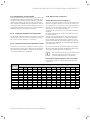
Provided the national regulations and technical standards
do not stipulate more stringent requirements, the following
applies:
> You must treat the heating water in the following cases:
– If the entire filling and supplementary water quantity
during the operating life of the system exceeds three
times the nominal volume of the heating installation
or
– If the limit values shown in the tables are not
observed.
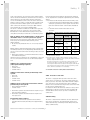
Overall hardness at smallest boiler heating
surface2)
> 20 l/kW <
20 l/kW
> 50 l/kW
50 l/kW
3
3
mol/m
mol/m3
mol/m
kW
(mg/l CaCO3) (mg/l CaCO3) (mg/l CaCO3)
No requirement or
2
0.02
< 50
(200)
(2.0)
< 31)
< (300)1)
2
1.5
0.02
> 50 to £ 200
(200)
(150)
(2.0)
1.5
0.02
0.02
> 200 to £ 600
(150)
(2.0)
(2.0)
0.02
0.02
0.02
> 600
(2.0)
(2.0)
(2.0)
Total heating
output
1) on systems with circulation water heaters and for systems with
electric heating elements
2) from the specific system volume (nominal capacity in litres/
heating output; for multiple boiler systems, the lowest individual
heating output should be used).
This data only applies up to 3 times the system volume for filling and top-up water. If 3 times the system volume figure is
exceeded, the water must be treated in exactly the same way as
if the limits quoted in tab. 2.2 were exceeded (softening, desalination, hardness stabilisation or desludging).
2.2 Guideline values for heating water: water hardness
Additives intended to remain permanently in the
system
–
–
–
–
Fernox F1
Fernox F2
Sentinel X 100
Sentinel X 200
Additives for frost protection intended to remain
permanently in the system
– Fernox Antifreeze Alphi 11
– Sentinel X 500
> Inform the operator about the measures required if you
have used these additives.
> Inform the operator about the measures required for
frost protection.
2.5.9 Pressure relief valve
The boiler is equipped with a pressure relief valve. This
safety device is required for all sealed central heating systems, is preset to 3 bar and is fitted with a 15 mm compression connection for the discharge pipe, whose diameter
must not be less than 15 mm. The pressure relief valve must
not be used for draining purposes.
For situations where the discharge cannot be easily routed
Vaillant have a remote pressure relief valve mounting kit
available which can be used to provide a suitable way to
achieve this.
2.5.10 Venting
Permissible water hardness
> Observe all valid national regulations and technical
standards when treating the filling and supplementary
water.
Installation and maintenance instructions ecoTEC plus 0020134833_01
The boiler is fitted with an automatic air vent. Other measures need to be taken to allow the heating system to be
either automatically or manually vented during filling and
during commissioning.
11
a
3 Description of the unit
3
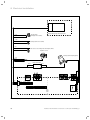
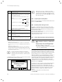
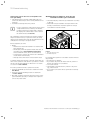
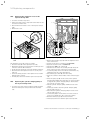
Description of the unit
5
6
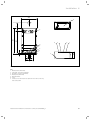
Design
The ecoTEC plus 937 consists of
– a 15 litre layered storage tank and
– a modified VUW boiler
Cold water that is heated by the VUW boiler is fed into the
insulated layered storage tank by a modulating cylinder
charging pump.
The VUW boiler supplies the layered storage tank with electrical energy for the cylinder charging pump.
7
4
9
3
10
11
2
1
8
1
12
13
14
15
19
18
17
16
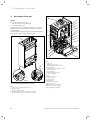
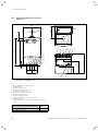
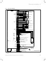
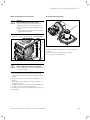
3.2 Boiler functional elements
2
3
4
5
3.1 Layered storage tank functional elements
Key
1 Layered storage tank expansion vessel
2 Impeller sensor
3 Cylinder charging pump
4 NTC temperature sensor for domestic hot water
5 Pressure relief valve for the layered storage tank
12
Key
1 Gas valve
2 Water pressure sensor
3 Venturi with mass flow sensor
4 Heat exchanger
5 Connection for the air/flue gas duct
6 Expansion vessel
7 Air intake pipe
8 Compact thermal module
9 Ignition electrode
10 Fan
11 Automatic air vent
12 Pressure gauge
13 Internal pump
14 Bypass valve
15 Expansion relief valve
16 Electronics box
17 Diverter valve with bypass
18 Impeller sensor (hot water)
19 Secondary heat exchanger
Installation and maintenance instructions ecoTEC plus 0020134833_01
Installation 4
4
Installation
i
BEFORE PROCEEDING - ENSURE BOILER IS
CORRECT FOR GAS GROUP SUPPLIED!
4.1.2
Installation and operation
Optional accessories are available for use in conjunction
with the installation and operation of the ecoTEC.
The current price list shows the complete range of hydraulic
accessories for the ecoTEC plus series.
The work described in this section must only be carried out
by a competent person.
4.2
4.1
Accessories
The layered storage tank and boiler are delivered preassembled in a packaging unit.
4.1.1
Controller
4.2.1
To control the ecoTEC, Vaillant offers various controller versions for connecting to the switching rail or for plugging
into the operator control screen.
Scope of delivery
Unpack the layered storage tank
> Remove the layered storage tank from its box.
> Remove the protective film from all parts of the layered
storage tank.
Room Thermostats
4.2.2 Unpacking the boiler
VRT 30 – Room Thermostat (230 V)
VRT 50 – Room Thermostat eBUS
> Remove the boiler from its box.
> Remove the protective film from all parts of the boiler.
Timers / Programmers
timeSWITCH 150 – mechanical clock
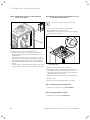
timeSWITCH 160 – 7 day programmer
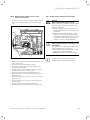
4.2.3 Checking the scope of delivery.
Digital Room Temperature Controls
> Check that the scope of delivery is complete and that all
parts are intact (¬ fig. 4.1 and ¬ tab. 4.2).
VRT 350 – Programmable Room Control
VRT 392f – RF Programmable Room Control *
VRT 350f – RF Programmable Room Control
Weather Compensating Controls
VRC 470 – Weather Compensator
VRC 470f – RF Weather Compensator
Communication
vrnetDIALOG
comDIALOG
Accessories
VR 65 – Control Centre
VR 66 – Control Centre
VR 61/2 – Two Zone Wiring Centre
VR 81/2 – Remote Control Unit
VR 68/2 – Solar Module
4.1 Controller accessories
* Note 392f RF transmitter wired external to boiler
Installation and maintenance instructions ecoTEC plus 0020134833_01
13
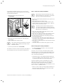
4 Installation
Item
12
1
11
10
2
3
9
4
QuanDescription
tity
1
2
3
4
1
1
1
4
5
6
6
4
7
3
8
9
10
11
12
1
1
1
1
1
Boiler
Lower cover of the boiler
Installation template
Service valves
Supply pipes (gas, heating, water, expansion relief
valve)
Adapter set, consisting of: connection pipes between
the layered storage tank and VUW boiler for heating
flow and return and water flow and return
Bags with parts incl. electrical plug and cable
clamps
Condensate discharge hose 1 m
Enclosure documentation
Lower cover of layered storage tank
Layered storage tank
Wall bracket
4.2 Scope of delivery for the ecoTEC plus boiler and layered
storage tank
8
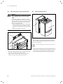
4.2.4 Disposing of the packaging
7
6
5
> Dispose of the cardboard packaging used on the ecoTEC
plus at a cardboard recycling site.
> Dispose of the plastic film and plastic filling at an appropriate plastic recycling site.
> Observe valid national regulations.
4.3
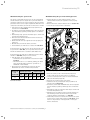
Transporting the appliance
Important:
With regards to the Manual Handling Operations, 1992 Regulations, the following lift operation exceeds the recommended weight for a one man lift.
General recommendations when handling
4.1 Scope of delivery for the ecoTEC plus boiler and layered
storage tank
14
> Clear the route before attempting the lift.
> Ensure safe lifting techniques are used – keep back
straight – bend using legs.
> Keep load as close to body as possible. Do not
twist – reposition feet instead.
> If 2 persons performing lift, ensure co-ordinated movements during lift.
> Avoid upper body/top heavy bending - do not lean
forward/sideways.
> Recommend wear suitable cut resistant gloves with good
grip to protect against sharp edges and ensure good
grip.
> Always use assistance if required.
Installation and maintenance instructions ecoTEC plus 0020134833_01
Installation 4
Removal of carton from delivery van
Recommend 2 person lift or 1 person with use of sack truck.
> If 1 person is performing lift, straddle the load, tilt and
place carton into position on truck.
> Recommend secure appliance onto truck with suitable
straps.
> Ensure safe lifting techniques are used – keep back
straight – bend using legs.
> Keep load as close to body as possible.
> If 2 persons performing lift, ensure co-ordinated movements during lift.
> Always use assistance if required.
Carriage of carton from point of delivery to point
of installation – ground floor.
Recommend 2 person lift or 1 person with use of sack truck.
> If 1 person is performing lift, straddle the load, tilt and
place carton into position on truck.
> Recommend secure appliance onto truck with suitable
straps.
> Ensure safe lifting techniques are used – keep back
straight – bend using legs.
> Keep load as close to body as possible.
> If 2 persons performing lift, ensure co-ordinated movements during lift.
> Clear the route before attempting the lift.
> If removing boiler from truck straddle the load and tilt
forwards to facilitate secure grip.
> Ensure safe lifting techniques are used – keep back
straight – bend using legs.
> Do not twist – reposition feet instead.
> Take care to avoid trip hazards, slippery or wet
surfaces and climbing steps and stairs.
> Always use assistance if required.
Carriage of carton from point of delivery to point
of installation – first or higher floor, cellar.
Recommend 2-person lift or 1 person with use of sack truck.
> If 1 person is performing lift, straddle the load, tilt and
place carton into position on truck.
> Recommend secure appliance onto truck with suitable
straps.
> Ensure safe lifting techniques are used – keep back
straight – bend using legs.
> Keep load as close to body as possible.
> If 2 persons performing lift, ensure co-ordinated movements during lift.
> Avoid upper body/top heavy bending - do not lean
forward/sideways.
> Clear the route before attempting the lift.
> If removing boiler from truck straddle the load and tilt
forwards to facilitate secure grip.
> Ensure safe lifting techniques are used – keep back
straight – bend using legs.
> Do not twist – reposition feet instead.
> Take care to avoid trip hazards, slippery or wet
surfaces and climbing steps and stairs.
> Always use assistance if required.
Installation and maintenance instructions ecoTEC plus 0020134833_01
Carriage of carton from point of delivery to point
of installation – roofspace.
> Recommend 2-person lift.
> Ensure co-ordinated movements during lift.
> Avoid upper body/top heavy bending - do not lean
forward/sideways.
> Clear the route before attempting the lift.
> Take care to avoid trip hazards, slippery or wet
surfaces and climbing steps and stairs.
> When transferring appliance into roofspace,
recommend 1 person to be in roofspace to receive the
appliance and other person to be below to pass up and
support appliance.
> Ensure safe lifting techniques are used – keep back
straight – bend using legs.
> Keep load as close to body as possible.
> Always use assistance if required.
> It is assumed safe access, flooring and adequate
lighting are provided in the roof space.
> It is recommended a risk assessment of the roof space
area be carried out before moving the appliance into the
area to take into account access, stability of flooring,
lighting and other factors, and appropriate measures
taken.
Unpacking of appliance from carton.
> Recommend 2 persons unpack appliance from carton.
> Always keep working area clear.
> Recommend straps and open carton flaps, then remove
items from the top including the polystyrene packing and
remove carton by sliding up over the boiler.
> Ensure safe lifting techniques are used – keep back
straight – bend using legs.
> Keep load as close to body as possible.
> Always use assistance if required.
> Dispose of packaging in a responsible manner.
> Recommend wear suitable cut resistant gloves with good
grip to protect against sharp edges and ensure good grip
when handling appliance outside packaging.
Positioning of Appliance for Final Installation –
no obstructions.
> If appliance weight is over 25 kg always use 2 persons to
move where practical.
> Fit bracket securely onto wall before lifting appliance
into position.
> Obtain firm grip on front and sides of appliance, lift
upwards, ensure stable balance achieved and lift
upwards to position in place on bracket.
> Ensure safe lifting techniques are used – keep back
straight – bend using legs - when lifting load from floor
level.
> Do not twist – reposition feet instead.
> Keep boiler as close as possible to body throughout lift
to minimise strain on back.
> Ensure co-ordinated movements to ensure equal spread
of weight of load.
> Always use assistance if required.
15
4 Installation
> Recommend wear suitable cut resistant gloves with good
grip to protect against sharp edges and ensure good grip
when handling appliance.
Positioning of Appliance for Final Installation –
above worktop, foreseeable obstructions etc.
> If appliance weight is over 25 kg always use 2 persons to
move where practical.
> Fit bracket securely onto wall before lifting appliance
into position.
> Obtain firm grip on front and sides of appliance, lift
upwards, onto worktop if practicable.
> Ensure stable balance achieved and lift upwards to
position in place on bracket.
> If 2 persons positioning onto bracket obtain firm grip at
front and sides/base of boiler.
> Ensure coordinated movements during 2 person lifts to
ensure equal spread of weight of load.
> Ensure safe lifting techniques are used – keep back
straight – bend using legs - when lifting load from floor
level.
> Do not twist – reposition feet instead.
> Keep boiler as close as possible to body throughout lift
to minimise strain on back.
> Avoid upper body/top heavy bending - do not lean
forward/sideways.
> Always use assistance if required.
> Recommend wear suitable cut resistant gloves with good
grip to protect against sharp edges and ensure good grip
when handling appliance.
Positioning of Appliance for Final Installation – in
roof space restricting installation.
> If appliance weight is over 25 kg always use 2 persons to
move where practical.
> Obtain firm grip on front and sides of appliance, lift
upwards, ensure stable balance achieved and lift
upwards to drop into place onto bracket.
> If 2 persons positioning onto bracket obtain firm grip at
front and sides/base of boiler.
> Ensure co-ordinated movements during 2 person lifts to
ensure equal spread of weight of load.
> If 1 person positioning onto bracket recommend obtain
firm grip supporting base of boiler.
> Ensure safe lifting techniques are used - keep back
straight – bend using legs - when lifting load from floor
level.
> Do not twist – reposition feet instead.
> Keep boiler as close as possible to body throughout lift
to minimise strain on back.
> Always use assistance if required.
> Recommend wear suitable cut resistant gloves with good
grip to protect against sharp edges and ensure good grip
when handling appliance.
> It is recommended a risk assessment of the roof
space area be carried out before moving the appliance
into the area to take into account access, stability of
flooring, lighting and other factors, and appropriate
measures taken.
Positioning of Appliance for Final Installation –
within compartment etc. restricting installation.
> If appliance weight is over 25 kg always use 2 persons to
move where practical.
> Fit bracket securely onto wall before lifting appliance
into position.
> Obtain firm grip on front and sides of appliance, lift
upwards, onto worktop if practicable.
> Ensure stable balance achieved and lift upwards to drop
into place onto bracket.
> If 2 persons positioning onto bracket obtain firm grip at
front and sides/base of boiler.
> Ensure coordinated movements during 2 person lifts to
ensure equal spread of weight of load.
> If 1 person positioning onto bracket recommend obtain
firm grip supporting base of boiler.
> Ensure safe lifting techniques are used – keep back
straight – bend using legs - when lifting load from floor
level.
> Do not twist – reposition feet instead.
> Keep boiler as close as possible to body throughout lift
to minimise strain on back.
> Always use assistance if required.
> Recommend wear suitable cut resistant gloves with good
grip to protect against sharp edges and ensure good grip
when handling appliance.
16
Installation and maintenance instructions ecoTEC plus 0020134833_01
Installation 4
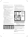
4.4
Requirements for the installation site
4.4.1
Required minimum clearances/
installation clearances
A
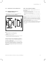
> When using accessories, observe the minimum clearances/installation clearances (¬fig.4.2).
C
D
An installation template is supplied with the boiler to aid
wall mounting.
The template shows the following:
– The position of the fixing holes for the hanging bracket.
– The position of the connections.
– The position of the wall breakthrough of the air/flue gas
duct.
Position the installation template vertically over the installation site.
> Attach the template to the wall, using tacks for example.
> Mark the drill holes for the hanging bracket on the wall.
> If necessary, mark the position for the wall breakthrough
for the air/flue gas duct.
> Remove the installation template from the wall.
> Drill 2 holes Æ 10 mm for the hanging bracket in the wall.
> If necessary, cut the wall breakthrough for the air/flue
gas duct.
B
C
4.4.2 Using installation templates
4.2 Recommended minimum clearances/installation clearances
Key
A 165 mm (air/flue gas duct Æ 60/100 mm)
246 mm (air/flue gas duct Æ 80/125 mm)
B 180 mm
C 5 mm; optimum approx. 50 mm
D 500 mm in front of the boiler to enable easy access for maintenance work (may be provided by an opening door).
Clearance at the side is not required, but the side panels
can also be removed if there is adequate side clearance (at
least approx. 50 mm) in order to facilitate maintenance or
repair work (¬ section. 4.9).
It is not necessary to ensure sufficient clearance between
the boiler and combustible materials or components as the
temperature of the boiler will always be less than the maximum permissible temperature of 85 °C due to its nominal
heat output.
Installation and maintenance instructions ecoTEC plus 0020134833_01
17
4 Installation
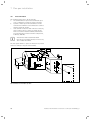
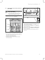
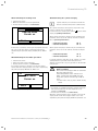
4.5
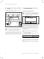
Dimension drawing and connection
dimensions
440
8
A
323
1
2
5
4
6
7
11
624
720
3
20
323
601
3
4
5
6
7
100
35
180
35
100
10
9
4.3 Connection dimensions for
ecoTEC plus VUI GB 376/5-5 in mm
Key
1 Wall breakthrough for air/flue gas duct
2 Hanging bracket
3 Heating flow (Æ 22 x 1.5)
4 Hot water connection (Æ 15 x 1.5)
5 Gas connection (Æ 22 x 1.5)
6 Cold water connection (Æ 15 x 1.5)
7 Heating return (Æ 22 x 1.5)
8 Air/flue gas duct connection
9 Condensate discharge connection Æ 19 mm
10 Condensate siphon
11 Heating expansion relief valve discharge pipe connection, Æ
15 mm
Minimum dimension from wall bracket to centre line of air/flue gas duct wall breakthrough
Dimension A
[mm]
60/100 with elbow 87°, PP
80/125 with elbow 87°, PP
175
223
4.3 Dimension A for air/flue gas duct wall breakthrough
18
Installation and maintenance instructions ecoTEC plus 0020134833_01
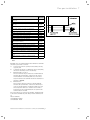
Installation 4
440
A
6
642
720
5
4
3
2
1
4
3
35
100
198
20
7
180
2
1
35
100
4.4 Layered storage tank connection dimensions in mm
Key
1 Heating return (Æ 22 mm)
2 Cold water connection (Æ 15 mm)
3 Hot water connection (Æ 15 mm)
4 Heating flow (Æ 22 mm)
5 Hanging bracket
6 Cover
7 Connection for discharge hose expansion relief valve on the layered storage tank
Installation and maintenance instructions ecoTEC plus 0020134833_01
19
4 Installation
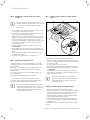
4.6
Wall-mounting the layered storage tank
a
Danger!
Risk of death if the load-bearing capacity
of the fixing elements used is insufficient!
If the fixing elements or wall do not have
sufficient load-bearing capacity, the layered
storage tank may come loose and fall down.
This may also cause leaks in the gas line,
which is potentially fatal.
> When installing the layered storage tank,
ensure that the fixing elements and the
wall have a sufficient load-bearing capacity.
> Check the quality of the wall.
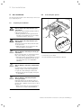
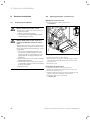
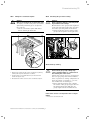
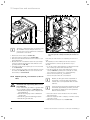
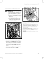
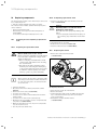
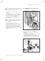
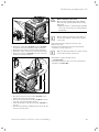
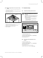
4.7
Wall-mounting the boiler
1
2
1
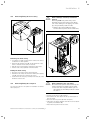
4.6 Wall-mounting the boiler
> Lift the VUW boiler (2) onto the layered storage tank so
that it is slightly above the hanging bracket on the layered storage tank (1).
2
3
4.5 Wall-mounting the layered storage tank
> Mount the hanging bracket (1) on the wall using the rawl
plugs and screws (2) provided with the unit.
> Hang the layered storage tank (3) on the suspension
bracket from above using the hanging bracket.
20
i
Raise the VUW boiler on both sides of the floor.
> Slowly lower the VUW boiler onto the hanging bracket on
the layered storage tank so that the suspension bracket
on the rear side of the VUW boiler completely engages
into the hanging bracket on the layered storage tank.
Installation and maintenance instructions ecoTEC plus 0020134833_01
Installation 4
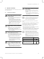
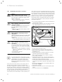
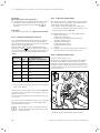
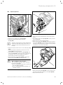
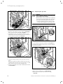
4.8
Removing/fitting the front casing
b
2
Caution.
Risk of damage caused by mechanical
tension.
Removing both side panels may cause
mechanical distortion in the boiler, which
can cause damage to the piping, for example, and potentially result in leaks.
> Always only remove one side panel,
never both side panels at the same time.
1
2.
4.7 Removing the front casing
3.
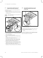
Removing the front casing
> Loosen the screw (1) on the bottom of the boiler using a
screwdriver or small spanner.
> Push in both retaining clips (2) on the underside of the
boiler so that the front casing is released.
> Pull the front casing forwards using the bottom edge.
> Lift the front casing upwards from the bracket.
1.
Fitting the front casing
> Place the front casing on the upper brackets.
> Push the front casing onto the boiler until both retaining
clips (2) snap into place at the front casing.
> Secure the front casing by screwing in the bolt (1) on the
underside of the boiler.
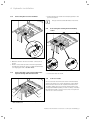
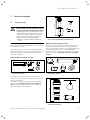
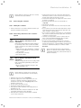
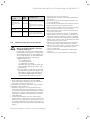
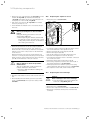
4.9
Removing/fitting the side panel
You can also remove a side panel for installation or maintenance purposes.
4.
4.8 Removing/fitting the side panel
b
Caution
Risk of damage to the side panel.
Unscrewed side panels that are merely suspended from the back wall can fall down.
> Hold onto the side panel when you are
unscrewing it, and always remove it from
the boiler.
> Fold the electronics box (1) forwards.
> Unscrew the two bolts (2.) from the top and bottom of
the side panel.
> Hold onto the side panel (3.) when doing this.
> Swivel the side panel outwards and remove it from below
by pulling it downwards (4.).
> Install the side panel in reverse order.
Installation and maintenance instructions ecoTEC plus 0020134833_01
21
5 Gas installation
5
Gas installation
5.2
Connecting the gas line
The work described in this section must only be carried out
by a competent person.
5.1
Preparing for installation
a
a
Danger!
Risk of death caused by improper gas
installation!
An incorrect gas installation may result in
leaks and an explosion.
> During installation, the legal directives
and the local regulations for gas supply
companies must be observed.
1
2
Danger!
Risk of death caused by improper gas
installation!
Tension in the gas line may result in leaks
or an explosion.
> Make sure there are no stresses in the
gas lines when it is installed.
3
4
5
7
6
8
b
Caution.
Risk of damage caused by incorrect gas
installation.
Excess test pressure or operating pressure
may cause damage to the gas valve.
> When the entire gas installation is tested
for leaks, the maximum pressure at the
gas valve must not exceed 0.75 kPa
(75 mbar).
b
Caution.
Risk of damage caused by contaminated
lines.
Foreign bodies such as welding remnants,
sealing residue or dirt in the supply lines
for gas can cause damage to the boiler.
> Blow the gas line thoroughly clean prior
to installation.
b
Caution.
Risk of damage caused by using the
wrong gas group.
Using the wrong gas group may cause a
fault shutdown on the boiler. Furthermore,
ignition and combustion noise may occur in
the boiler.
> Only use propane gas for propane-fired
boilers in accordance with DIN 51622.
22
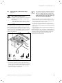
5.1 Fitting the gas connection
> Connect the gas as shown.
> Use the extended gas pipe (2) that is supplied.
Installation and maintenance instructions ecoTEC plus 0020134833_01
Hydraulic installation 6
6
Hydraulic installation
The work described in this section must only be carried out
by a competent person.
6.1
b
Caution.
Risk of damage caused by heat transfer
when soldering.
Heat that is transferred during soldering
may cause damage to the seals in the service valves.
> Do not solder the connection pieces if
the connection pieces are screwed to the
service valves.
i
Seals made of rubber-like materials may be subject to plastic deformation, which can lead to
pressure losses. We recommend using seals
made of a paste-like fibre material.
Preparing for installation
a
Danger!
Risk of death caused by an incorrectly
installed system!
Heating water that leaks from the discharge
pipe of the expansion relief valve may
cause severe burns.
> Install the expansion relief valve and its
discharge pipe opening ensuring that
there is no danger to persons in or about
the building. This may be outside or to a
suitable open drain in the installation
room.
> Make sure that the drain is visible.
b
Caution.
Risk of damage caused by contaminated
lines.
Foreign bodies such as welding remnants,
sealing residue or dirt in the water pipes
may cause damage to the boiler.
> Flush the heating installation thoroughly
prior to installation.
b
Caution.
Risk of damage from corrosion.
If non-diffusion-tight plastic pipes are used
in the heating installation, this may cause
air to enter the heating water and corrosion
of the heat generation circuit and the
boiler.
> If using non-diffusion-tight plastic pipes
in the heating installation, separate the
system by installing an external heat
exchanger between the boiler and the
heating installation.
a
Danger!
Risk of scalding and/or damage due to
incorrect installation leading to leaking
water.
Stresses in the supply line may cause leaks.
> Make sure there are no stresses in the
supply lines when they are installed.
Installation and maintenance instructions ecoTEC plus 0020134833_01
The layered storage tank is fitted with a 1 litre expansion
vessel.
The Vaillant ecoTEC boiler is equipped with a 10 l expansion
vessel with a gas-side filling pressure of 0.075 MPa
(0.75 bar), which is suitable for a closed heating system
with a maximum water volume of 100 litres.
> Before installing the boiler, check whether the volume of
the installed expansion vessel is sufficient.
> If the volume of the expansion vessel is insufficient, then
install an additional expansion vessel connected as close
to the boiler as possible into the heating return pipe.
i
When using an external expansion vessel
together with a VUI boiler, it is advisable to
install a non-return valve in the outlet (heating
flow) or take the internal expansion vessel out of
service.
Otherwise, the warm start function may be more
frequently activated because of backflow, which
causes unnecessary energy loss.
Vessel volume
(in l)
Initial system pressure (in bar)
Expansion relief valve setting (in MPa
(bar))
With system volumes greater than 100 l,
multiply the volume by the adjacent factor.
1.0
1.5
0.3 (3.0)
0.109
0.156
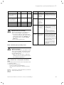
6.1 Size of an additional expansion vessel
23
6 Hydraulic installation
6.2
> Fit the supplied pipe elbows and straight pipelines in the
specified sequence.
Connecting the hot and cold water
i
6.4
The pipe elbows (1) and (2) must be fitted first.
Connecting the heating flow and heating
return
7
6
13
1
2
3
4
5
6.1 Fitting the hot and cold water connection
11
1
12
10
> Make the domestic hot and cold water connections as
shown.
> Ensure correct water pressure and flow requirements
and that any expansion can be accommodated with the
cold supply pipe work (¬ section 2.5.7).
2
6
8
7
9
4
3
5
6.3 Fitting the heating flow and heating return
6.3
Connecting pipe connections between the
layered storage tank and the boiler
> Connect the water as shown.
6.5
Low loss header
A low loss header disconnects the boiler from the heating
system. The system is no longer dependent on the remaining feed head of the boiler. In conjunction with the boiler
circulation pump, the low loss header ensures that a sufficiently high minimum quantity of water is always circulating
through the boiler. No electrical accessories are required in
order to use a low loss header.
1
2
3
4
6.2 Fitting the pipe connections between the layered storage
tank and the boiler
24
Installation and maintenance instructions ecoTEC plus 0020134833_01
Hydraulic installation 6
6.6
i
Connecting the condensate discharge
pipework
Danger!
Risk of death from flue gases!
An empty or insufficiently filled condensate
siphon may allow flue gas to escape into
the room air.
> Make sure that the condensate siphon is
filled with water when switching on the
boiler.
a
The ecoTEC plus boilers are equipped with a condensate
siphon. (The filling height is 145 mm). The siphon collects
the condensate that has formed in a vessel with a capacity
of approx. 200 ml, and intermittently deposits the contents
to the discharge pipe. This minimises the risk of the discharge pipe freezing up.
The condensate discharge pipework must have a
continuous fall (45 mm per metre) and should
whenever possible terminate at a suitable discharge point within the heated envelope of the
building that will remain frost free under long
periods of low external temperatures.
> During installation remove all burs from inside of cut
pipe work and avoid excessive adhesive which may trap
small pockets of water close to the pipe wall which can
freeze and build into a larger ice plug.
> As with other pipe work insulate the condensate discharge pipe to minimise any risk of freezing and beware
when crossing cavities that the fall is maintained and the
pipe sleeved.
> The condensate discharge pipework must terminate in a
suitable location.
Further information can be obtained from "BS 6798 Specification for installation of gas–fired boilers of rated input not
exceeding 70 kW net". Before starting up the boiler, the
condensate siphon (2) must be filled with water, as
described in the relevant section.
1
2
3
4
a
d
c
b
6
3
Internal
stackpipe
3
5
Internal
discharge system
7
Gulley
Soakaway
6.4 Condensate discharge pipework
> Connect the condensate discharge (1) of the boiler to a
condensate discharge pipework (3) which has a minimum
internal diameter of 19 mm (22 mm outside diameter for
all external pipes) and is made from an acid-resistant
material (e.g. plastic overflow pipe).
Installation and maintenance instructions ecoTEC plus 0020134833_01
25
6 Hydraulic installation
6.7
Connecting the discharge pipe to the
expansion relief valve on the boiler
6.8
Connecting the discharge hose to the
expansion relief valve on the layered
storage tank
The expansion relief valve for the heating installation is
integrated in the boiler.
> Install the discharge pipe for the expansion relief valve
so that it does not interfere with the removal and fitting
of the siphon trap.
i
We recommend that you do not shorten the discharge pipe supplied.
2
1
min.
180
1
2
3
6.5 Fit the discharge pipe on the expansion relief valve
> Leave an installation space of at least 180 mm beneath
the condensate siphon.
> Insert a seal (1) in the cap nut (2).
> Screw the discharge pipe (3) onto the expansion relief
valve.
> Make the drain line routing as short as possible and in a
downward gradient away from the boiler.
> Allow the line to terminate in such a way that nobody
can be injured and no cable or other electrical components can be damaged if water or steam is ejected.
> Note that the end of the line must be visible.
> If the pipe cannot fall to a safe discharge point then the
Vaillant remote pressure relief valve mounting kit can be
used to provide a suitable way to achieve this.
> Ensure the discharge pipe work is installed, routed and
terminated correctly to minimise the risk of freezing up.
26
6.6 Fitting the discharge hose to the expansion relief valve on
the layered storage tank
The expansion relief valve for the hot water system is integrated into the layered storage tank.
> Insert the discharge hose (1) into the expansion relief
valve (2).
The end of the discharge hose can be guided via an open
connection to a tundish and can be connected in a similar
way to the discharge line for the boiler.
Installation and maintenance instructions ecoTEC plus 0020134833_01
Flue gas installation 7
542
Air/flue gas duct
48
a
Danger!
Risk of death and risk of damage caused
by using non-approved air/flue gas ducts!
Vaillant boilers are system-certified only in
combination with genuine Vaillant air/flue
gas ducts. The use of other accessories
may cause personal injury and material
damage as well as operating faults.
> Only use genuine Vaillant air/flue gas
ducts.
901
7.1
Flue gas installation
1456
7
7.2 Scope of delivery for the vertical air/flue gas duct
Article number 0020060570 and 0020065937
Optional 125 mm air/flue gas duct
The CE mark is valid only if the appliance is operated with
Vaillant air/flue gas ducts.
All ecoTEC plus boilers feature a Æ 60/100 mm diameter
air/flue gas connection as standard. Selecting the most suitable system depends on the individual installation and
application conditions.
A concentric air/flue gas ducting with an outer diameter of
125 mm is available and it can be extended depending on
the boiler output range. The flues gas spigot Ø 80/125 (with
2 measuring apertures) Art. No.: 0020147469 will be
required. You can also get a vertical system. For more information refer to the ¬ installation manual for the air/flue
gas duct.
Standard 100 mm air/flue gas duct
87
65
48
74
15
667
1020
30
70
70
7.1 Scope of delivery for the horizontal air/flue gas duct
Article number 303933
7.3 Scope of delivery for the horizontal air/flue gas duct
Article number 303209
70
1430
A concentric air/flue gas duct with an outer diameter of
100 mm that can be extended depending on the boiler output range is available.
You can also get a vertical system. For more information
refer to the ¬ installation manual for the air/flue gas
duct. 87° elbows and 45° elbows are also available for
greater flexibility during installation.
7.4 Scope of delivery for the vertical air/flue gas duct
Article number 303200
Installation and maintenance instructions ecoTEC plus 0020134833_01
27
7 Flue gas installation
7.2
Flue termination
The following details refer to all flue systems.
a.
The terminal must be positioned such that the products of combustion can disperse freely at all times.
b.
A plume of water vapour will sometimes be visible
from the flue terminal. Positions where this could be a
nuisance should be avoided.
c.
If the terminal is fitted less than 2 m above a balcony,
above ground or above a flat roof to which people
have access then a suitable terminal guard must be
provided and fitted (contact Tower Flue Components,
Tonbridge, TN9 1TB).
i
Vertical flues must not terminate within
600 mm of an openable window, air vent or any
other ventilation terminal.
The flue system shall be so placed or shielded as to prevent
ignition or damage to any part of the building.
P
Q
I
Q
Q
T
Q
S
Q
R
F
D, E
G
A
I
N
O
C
M
B
L
N
H
H
M
J
K
7.5 Termination of the air/flue gas duct
28
Installation and maintenance instructions ecoTEC plus 0020134833_01
Flue gas installation 7
Location
A
Minimum
dimensions
Directly below an opening, air brick, opening win300 mm
dows, etc.
B Above an opening, air brick, opening window, etc. 300 mm
C
Horizontally to an opening, air brick, opening win300 mm
dow, etc.
D
Below temperature-sensitive building components
75 mm
e.g. plastic gutters, soil pipes or drain pipes
E
F
G
H
I
J
K
Below eaves
Below balconies or car port roof
From a vertical drain pipe or soil pipe
From an internal or external corner
Above ground, roof or balcony level
From a surface facing the terminal
From a terminal facing the terminal
200 mm
200 mm
150 mm
200 mm
300 mm
600 mm
1200 mm
L
From an opening in the car port (e.g. door, window) into the dwelling
1200 mm
M
N
O
P
Q
Vertically from a terminal on the same wall
Horizontally from a terminal on the same wall
From the wall on which the terminal is mounted
From a vertical structure on the roof
Above intersection with roof
Horizontally to a window or opening on pitched or
R
flat roofs
Above a window or opening on pitched or flat
S
roofs
Below a window or opening on pitched or flat
T
roofs
7.6 Termination of air/flue gas duct under balcony or eaves
1500 mm
300 mm
0 mm
N/A
300 mm
600 mm
600 mm
2000 mm
7.1 Position of the termination in a fan-assisted air/flue gas
duct
BS 5440–1 It is recommended that the fanned flue terminal
should be positioned as follows:
a)
at least 2 m from an opening in the building directly
opposite, and
b)
so that the products of combustion are not straightly
directed to discharge across a boundary.
1)
Dimensions D, E, F and G:
These clearances may be reduced to 25 mm without
affecting the performance of the boiler. In order to
ensure that the condensate plume does not affect
adjacent surfaces the terminal should be extended as
shown in ¬ fig. 7.6.
2)
Dimension H:
This clearance may be reduced to 25 mm without
affecting the performance of the boiler. However, in
order to ensure that the condensate plume does not
affect adjacent surfaces a clearance of 300 mm is
preferred. For IE, recommendations are given in the
current edition of IS 813.
For 1 and 2 above you can use the Variable Termination Kit
to move the termination point away from the building fabric.
Article numbers:
0020060584 - White
0020060585 - Black
Installation and maintenance instructions ecoTEC plus 0020134833_01
29
8 Electrical installation
8
Electrical installation
8.2
Opening/closing the electronics box
Opening the electronics box
8.1
Preparing for installation
e
Danger!
Risk of death from electric shock!
Touching live connections may cause serious personal injury.
> Switch off the power supply.
> Secure the power supply against being
switched back on again.
e
Danger!
Risk of death from electric shock as a
result of an improper electrical connection!
An improper electrical connection may negatively affect the operational safety of the
boiler and result in material damage or personal injury.
> The electrical installation must be carried out by a suitably qualified competent person who is responsible for complying with the existing standards and
guidelines.
> Connect the boiler in accordance with BS
7671 (IEE Regulations).
> For IE: Please observe the latest edition
of the ETCI regulations (Electro-Technical
Council for Ireland).
> Earth the boiler.
> Remove the front casing from the boiler
(¬ section 4.8).
3
1
4
2
8.1 Opening the back wall of the electronics box
> Fold the electronics box (1) forwards.
> Undo the 4 clips of the rear cover (2) of the electronics
box from the brackets (3) at the rear and sides of the
electronics box.
> Fold up the cover.
Closing the electronics box
>
>
>
>
Close the rear panel on the electronics box.
Push in the panel until it clicks into place in the clips.
Fold up the electronics box.
Push the right and left clips of the box against the side
panels on the boiler until they click into place.
> Attach the front casing of the boiler
(¬ section 4.8).
30
Installation and maintenance instructions ecoTEC plus 0020134833_01
Electrical installation 8
Connecting the layered storage tank to the
power supply
2
X12
b
Caution.
Risk of cable damage.
Cables may become damaged if they come
into contact with hot parts of the unit.
> Observe the routing of the cable.
1
X31
8.3
> Open the electronics box (¬ section 8.2).
8.3 Cable routing in the electronics box
1
2
3
> Guide the pump cable (2) with the plug X12 along the
outside of the electronics box.
> Plug the pump cable's plug X12 into the slot X12 (righthand side of the PCB).
> Guide the sensor cable (1) with the plug X31 to the PCB.
> Plug the sensor cable's plug X31 into the slot X31 (lefthand side of the PCB).
> Secure the cable over the cable terminals in the electronics box.
8.2 Cable routing on the underside of the unit
> Guide the layered storage tank's cable harness (2) with
the grommets (3) through the attached cable ducts on
the layered storage tank and boiler.
On the boiler, use the cable duct (1).
> Secure the grommets on the cable ducts using the
enclosed spring clips.
Installation and maintenance instructions ecoTEC plus 0020134833_01
31
8 Electrical installation
e
Danger!
Risk of death from electric shock!
Mains connection terminals L and N remain
live even if the continuous voltage on/off
switch is turned off.
> Before establishing a mains connection,
switch off the power supply.
b
Caution.
Risk of damage caused by an incorrect
connected voltage.
At mains voltages greater than 253 V and
less than 190 V, the functions may be
impaired.
> Make sure that the rated voltage of the
mains is 230 V.
b
Caution.
Risk of damage caused by incorrect
installation.
A mains voltage at the incorrect plug terminals on the ProE system may destroy the
electronics.
> Only connect the mains connection cable
to the terminals marked for the purpose.
b
Caution.
Risk of damage caused by incorrect
installation.
Connecting wires that have been stripped
too far may cause short circuits and damage the electronics if a strand accidentally
comes loose.
> Only strip the outer sheathing of flexible
cables for a maximum of 3 cm to prevent
short circuits.
> Lay the lines correctly.
> Use strain reliefs.
i
If you install the boiler in safety area 2, it can
only be operated if it is room-sealed. Installation
method B53P is not permitted in this case.
Observe the latest edition of the "IEE Wiring
Regulations – BS7671, Requirements for Electrical Installation".
In IE, reference should be made to the current edition of
the ETCI (Electro-Technical Council for Ireland) rules.
The boiler is supplied for connection to 230 V, ~ 50Hz supply fused at 3 A rating. Connection to the mains supply
shall be made via a fused 3 pin plug to an unswitched shuttered socket, both complying with the requirements of
BS 1363. (Alternatively, connection may be made via a 3 A
fused double pole isolator having a contact opening of at
32
least 3 mm in all poles and supplying the boiler and controllers only). The point of connection to the mains supply must
allow complete electrical isolation of the boiler and its ancillary controllers. It should be readily accessible and adjacent
to the boiler. A 3 core flexible cord according to BS 6500
tables 6, 8 or 16 (3 x 0.75 to 3 x 1.5 mm2) should be used.
The nominal voltage of the mains must be 230 V; at mains
voltages greater than 253 V and less than 190 V the functions may be impaired.
> Use a normal commercial mains connection cable that is
compliant with standards.
> Route the mains connection cable through the left cable
duct (¬ fig. 8.1, pos. 4) on the base of the unit.
1
X12
Establishing the mains connection
X31
8.4
2
8.4 Cable routing of the mains connection cable
> Use the strain reliefs (1) provided.
> Shorten the mains connection cable as necessary.
> Only strip the outer sheathing of the supply lines to a
maximum of 3 cm.
> Ensure that the inner conductor insulation is not damaged when stripping the outer sheathing.
> Only strip inner conductors just enough to establish
good, sound connections.
> Fit the stripped ends of the conductors with crimp pin
terminals to ensure a secure connection free from loose
strands and to thus prevent short circuits.
> Connect the provided green ProE plug (2) for the mains
connection to the mains connection cable using a screwdriver.
> Insert the ProE plug into the corresponding PCB slot (L,
N and earth) (¬ fig. 8.4).
> Lay the lines correctly.
> Secure the cable in the electronics box using the strain
reliefs.
> Close the electronics box (¬ section 8.2).
Installation and maintenance instructions ecoTEC plus 0020134833_01
Electrical installation 8
i
Ensure that the connection cables are securely
fastened to the plug terminals.
8.5
Connecting the controller
8.5.1
Fitting the controller
> Fit the controllers in accordance with the relevant operating and installation instructions.
8.5.2 Connecting controllers to the electronic
system
b
Caution.
Risk of damage caused by incorrect
installation.
Connecting wires that have been stripped
too far may cause short circuits and damage the electronics if a strand accidentally
comes loose.
> Only strip the outer sheathing of flexible
cables to a maximum of 3 cm to prevent
short circuits.
> Lay the lines correctly.
> Use strain reliefs.
b
Caution.
Risk of damage caused by incorrect
installation.
A mains voltage at the incorrect plug terminals on the ProE system may destroy the
electronics.
> Do not connect a mains voltage to the
eBUS terminals (+/-).
i
Ensure that the conductors are securely fastened to the plug terminals of the ProE plug.
> Fit the stripped ends of the conductors with crimp pin
terminals to ensure a secure connection free from loose
strands and to thus prevent short circuits.
> Connect the ProE plug to the supply lines of the controller using a screwdriver.
> Insert the ProE plug into the associated PCB slot
(¬ fig. 8.5).
> Lay the lines correctly.
> Secure the cable in the electronics box using the strain
reliefs.
> If you connect a 230 V AC time and temperature control
to the boiler, then remove the bridge at input 24 V = RT
(X100 or X106) if a bridge exists.
> If you connect a weather compensator or room temperature control via eBUS, then bridge input 24 V = RT (X100
or X106) if no bridge exists.
> I If using low voltage (24 V) controls connect these in
place of the bridge marked RT 24 V (X100 or X106).
> Close the electronics box (¬ section 8.1).
> In order to achieve pump operating mode "Comfort"
(continuously running pump) for multi-circuit controllers,
change the diagnostics code D.018 Pump operating mode
from "Eco" (intermittent pump) to "Comfort" (¬ section 11.1.2).
i
Please note that the bridge at the ProE plug
(Burner off) must be removed when connecting
a maximum thermostat (contact thermostat) for
underfloor heating.
> Open the electronics box (¬ section 8.2).
> Route the supply lines of the components to be connected (e.g. external controllers, external sensors)
through the left cable duct (¬ fig. 8.1, pos. 4) on the
underside of the boiler.
> Use the strain reliefs (1) provided.
> Shorten the supply lines as necessary.
> Only strip the outer sheathing of the supply lines to a
maximum of 3 cm.
> Ensure that the inner conductor insulation is not damaged when stripping the outer sheathing.
> Only strip inner conductors just enough to establish
good, sound connections.
Installation and maintenance instructions ecoTEC plus 0020134833_01
33
8 Electrical installation
8.6
Connecting additional components
b
Caution.
Risk of damage caused by incorrect
installation.
Connecting wires that have been stripped
too far may cause short circuits and damage the electronics if a strand accidentally
comes loose.
> Only strip the outer sheathing of flexible
cables to a maximum of 3 cm to prevent
short circuits.
> Lay the lines correctly.
> Use strain reliefs.
You can actuate an additional component with the aid of
the auxiliary relay that is installed in the ecoTEC plus VUI
GB 937 and you can actuate two other components using
the multi-functional module.
You can actuate the following components:
– Circulation pump
– External pump
– Cylinder charging pump
– Extractor hood
– External solenoid valve
– External fault signal
– Solar pump (not active)
– eBUS remote control (not active)
– Legionella protection pump (not active)
– Solar valve (not active)
8.6.1
Connecting an auxiliary relay (grey plug on
the PCB)
i
You can connect the additional component to
the integrated auxiliary relay using the grey plug
on the PCB.
> Perform the wiring in the same way as in ¬ section 8.5.
> To start up the connected components, select the components using diagnostics code "D.026" in the installer
level (¬ section 11.1).
8.6.2 Connecting a VR 40 – "2 from 7" multifunctional module
> In the installer level, select diagnostics code "D.028" to
actuate relay 2 on the multi-functional module (¬ section 11.1).
8.7
Actuating the circulation pump
demand-controlled
You can actuate the circulation pump for a domestic hot
water cylinder demand-controlled using the ecoTEC plus.
b
Caution.
Risk of damage caused by incorrect
installation.
Connecting wires that have been stripped
too far may cause short circuits and damage the electronics if a strand accidentally
comes loose.
> Only strip the outer sheathing of flexible
cables to a maximum of 3 cm to prevent
short circuits.
> Lay the lines correctly.
> Use strain reliefs.
> Perform the wiring in the same way as in ¬ section 8.5.
> Connect the supply line of the external button with terminals X41/1 (0) and X41/6 (FB) on the PCB (¬fig. 8.5).
i
i
The edge connector required for this is included
with your controller.
i
Using a circulation pump negatively affects hot
water comfort, as it causes turbulence and disrupts the stratification in the cylinder.
To operate a circulation pump, we recommend
using the accessory set with article number
0020057235.
> Limit the flow rate of the circulation pump in order to
prevent the hot water handling from being negatively
affected.
i
Using a circulation pump increases energy consumption.
You can connect additional components to the ecoTEC plus
using the Vaillant multi-functional module 2 in 7 (accessories).
> Fit the components in accordance with the relevant operating and installation instructions.
> In the installer level, select diagnostics code "D.027" to
actuate relay 1 on the multi-functional module (¬ section 11.1).
34
Installation and maintenance instructions ecoTEC plus 0020134833_01
Electrical installation 8
Connection diagrams
X22
X25
white
Pump PWM signal
8
7
2
1
5
3
11
10
+
+
1
2
3
4
5
6
DCF
Bus
X16
L
N
X11
L
N
grey
blue
X18
Impeller
sensor
orange
Warm start sensor
violet
Hot water sensor
red
Flow sensor
blue
Return sensor
Coding resistor, gas group
6FB
AF
RF
+
pink
Water pressure
sensor
Coding resistor, output range
white
24 V
230 V~
Diverter
valve
Safety fuse
Burner RT
off
24
X100
Mass flow
sensor
M
1
3
4
1
2
3
1
blue
Stepper motor
+
9
6
12
8
17
7
18
14
13
X2 113
blue
2
6
4
12
5
1
5
7
8
7
12
X20 13
pink
2
15
16
4
3
17
3
X24
white
17
X41
Holding magnet
1
2
3
4
5
6
4
Edge
connector
Gas valve
L
N
0
0
Circulation pump remote control
External sensor
External temperature sensor
DCF connection
Earth
Earth
Contact thermostat/burner off
24 V DC room thermostat
Bus connection
(Controller/room th. digital)
Auxiliary relay *
(Selection by D.026)
1 2
4 5
PWM
Earth
X51
Display
Connection
+ 24 V
Hall signal
8.8
Fan
N L
Internal pump *
green
Ignition
unit
X1
turquoise
RT
L
N
No function *
230 V AC room thermostat *
Ignition
electrode
Mains connection
Appliance earth
* ... variant-dependent
8.5 Connection diagram for the electronics box on the ecoTEC
plus 937
Installation and maintenance instructions ecoTEC plus 0020134833_01
35
8 Electrical installation
violet
Shift load storage tank electronics
Storage tank
charging sensor (NTC)
black
orange
Storage tank sensor (NTC)
black
blue
Inlet sensor secondary heat exchanger (NTC)
black
Impeller sensor
Storage tank charging pump
green
black
red
X41
X11
N
L
X1
X12
X18
RT
Bus
X100
L
N
N
L
Burner RT
off
24
+
1
0
0
black
X31
X20
X24
X25
X2
24 V
230 V~
black
red
grey
brown
black
DCF
6FB
AF
RF
Plug connection
brown
8.6 Connection diagram for the layered storage tank
36
Installation and maintenance instructions ecoTEC plus 0020134833_01
Operation 9
9
Operation
The Vaillant ecoTEC plus boiler is fitted with a digital information and analysis system (DIA). If additional settings are
required, which have not yet been configured using the
installation assistant, you can view and modify further
parameters using the DIA.
The operating concept and operation of the boiler is
described in the ¬ operating instructions of the boiler. The
read-off and setting facilities of the operator level are also
described in the ¬ operating instructions.
The following overview shows the read-off and setting facilities of the installer level.
9.1
Calling up the installer level
b
Caution.
Risk of damage caused by incorrect handling.
Incorrect settings at installer level can
cause damage to the heating installation.
> You should only access the installer level
if you are an approved competent person.
The installer level is secured against unauthorised access
with a password because incorrect parameter settings at
this level may cause functional faults and damage to the
heating installation.
and right
selection
> Press the left
buttons ("i") simultaneously
The following menu appears on the display.
or the plus but> Scroll using the minus button
until the menu point "Installer level"
ton
appears.
to
> Press the right-hand selection button
select the menu point.
"Enter code" and the value "00" appear in the display.
> Select the value 17 (code) using the minus button
or the plus button
.
to con> Press the right-hand selection button
firm the entered code.
The installer level appears with a selection of menu points.
i
In the following, a path specification at the
beginning of an action instruction specifies how
to access this function in the installer level, e.g.
Menu ¬ Installer level ¬ Test programs ¬ Test
programs.
i
If you exit the installer level and then access it
again within 15 minutes, you do not have to
enter the code again.
Installation and maintenance instructions ecoTEC plus 0020134833_01
37
9 Operation
9.2
Overview of the menu structure
Menu
Information
Reset burner off time
Installer level
Back
Select
Installer level
Fault list
Test programmes
Appliance config.
Enter code
17
Back
Ok
Back
Select
Installer level
Fault list
Test programmes
Appliance config.
Back
Select
F.00
F.75
Interruption
Flow Fehler
sensor
Pumpe/Wassermangel
Test programmes
Gas type check
Test programmes
Function menu
Back
Select
Test programmes
Gas type check
Test programmes
Function menu
Back
Select
Test programmes
Gas type check
Function menu
Self test Electronics
Back
Select
Test programmes
Gas type check
Function menu
Self test Electronics
Back
Installer level
Test programmes
Appliance config.
Diagnosis menu
Back
Select
Select
Appliance config.
Language
Target flow temp.
DHW temperature
Back
Select
Appliance config.
Language
Target flow temp.
DHW temperature
Back
Select
Appliance config.
Language
Target flow temp.
DHW temperature
Back
Select
Gas type check
Select
gas type
LPG
Back
Select
P.00 Exhaust
P.00 Pump
Entlüftung
run
Pumpe
Clockedwird
taktend
angesteuert
Back
Select
Back
Select
T.01
T.01
internal pump
interne Pumpe
Back
Back
Select
Select
Self test
Self diagnosis
of the electronics
Back
Select
Language
02 English
Cancel
Ok
Target flow temp.
41
Cancel
Ok
DHW temperature
35
Cancel
Ok
9.1 Overview of the menu structure for installer level part 1
38
Installation and maintenance instructions ecoTEC plus 0020134833_01
Operation 9
Appliance config.
Target flow temp.
DHW temperature
Comfort mode
Back
Select
Appliance config.
DHW temperature
Comfort mode
Auxiliary relay
Back
Select
Appliance config.
Comfort mode
Auxiliary relay
Accessory relay 1
Back
Select
Appliance config.
Auxiliary relay
Accessory relay 1
Accessory relay 2
Back
Select
Appliance config.
Accessory relay 1
Accessory relay 2
Heating partial load
Back
Select
Appliance config.
Accessory relay 2
Heating partial load
Contact data
Back
Select
Appliance config.
Heating partial load
Contact data
Factory setting
Back
Installer level
Testprogramme
Appliance config.
Diagnosis menu
Back
Select
Installer level
Appliance config.
Diagnosis menu
Start inst. assistant
Back
Select
Select
Comfort operation
Comfort on
Cancel
Ok
D.026
D.026
Auxiliary relay
Zusatzrelais
Circulation pump
externe Pumpe
Back
Cancel
Ok
D.027
D.027
Accessory relay 1
Zubehörrelais 1
Circulation pump
externe Pumpe
Back
Cancel
Ok
D.028
D.028
Accessory relay 2
Zubehörrelais 2
Circulation pump
externe Pumpe
Back
Cancel
Ok
D.000
Heating partial load
0
Cancel
Ok
Contact data
Phone number
Back
D.096
Reset to
factory settings?
Cancel
Ok
D.000
D.001 partial load
Heating
Pumpennachlauf
Heizung
auto
0
Back
Back
To start the
Competent Installer
press OK
Cancel
Ok
9.2 Overview of the menu structure for installer level part 2
Installation and maintenance instructions ecoTEC plus 0020134833_01
39
10 Commissioning
10
Commissioning
At the time of commissioning, complete all relevant sections of the benchmark checklist found within the back
pages of this document.
Ensure that the filling and purging programs P.06 and P.00
have been allowed to run fully before the boiler is ignited
for the first time.
a
i
Danger!
Risk of poisoning and burns caused by
escaping hot flue gas!
Hot flue gas can escape and cause poisoning and burns if the boiler is operated with
an incompletely fitted or open air/flue gas
duct or if the boiler is operated with internal leaks with the front casing open.
> Operate the boiler
- for commissioning
- for testing purposes
- in continuous operation
only when the front casing is fitted and
closed and the air/flue gas duct is completely fitted.
> For test purposes only, such as gas flow
pressure testing, the boiler may be operated with the front casing removed for
short durations ONLY but must have a
completely installed air/flue gas duct.
The automatic air vent cap must be released
before filling the heating circuit or recharging
circuit and during operation.
Purge the heating circuit or the recharging circuit using the purge program P.00 (¬ section 10.4).
each time the unit is switched on until all steps have been
completed successfully.
You must confirm the start of the installation assistant.
Once confirmed, all of the heating and hot water requirements from the boiler are blocked. This status remains until
the installation assistant is completed or cancelled.
If you do not confirm the start of the installation assistant,
it will be closed 10 seconds after being switched on and the
basic display will appear. The next time the boiler is
switched on using the on/off button, the installation assistant will be started again.
10.2.1 Language
> Select the required language using the minus or plus
button.
> Press the right-hand selection button to confirm the
selected language.
The language change must be confirmed a second time in
order to avoid an unintentional change.
i
If you unintentionally select a language that you
cannot understand, you can change it again as
described below.
> Press the right-hand selection button and the plus button simultaneously and hold them down.
> Press the fault clearance key for a short time.
> Press and hold the right-hand selection button and the
plus button until the option for changing the language
appears on the display.
> Select the language of your choice using the minus button or the plus button.
> Confirm the change by pressing the right-hand selection
button ("OK").
Auxiliary service equipment:
10.2.2 Filling mode
The following test and measuring equipment is required for
commissioning:
– CO2 measuring instrument
– Digital or U-tube manometer
Filling mode (test program P.06) is activated automatically
in the installation assistant for as long as it appears on the
display. (¬ section 10.4).
10.1
10.2.3 Purging
Switching on the boiler
> Press the on/off button (¬ Operating instructions).
The basic display appears on the display.
10.2
Installation assistant
The installation assistant is launched when the boiler is
switched on for the first time. It provides easy access to the
most important test programs and configuration settings
for installing the boiler. The installation assistant appears
40
> Start test programme P.00 to purge the system (¬ section 10.4).
Unlike the way in which it is started in the test programs
menu, the purge program P.00 is started in the installation assistant by pressing the minus button or the plus
button.
In order to change the circuit that is being purged, you
can press the right-hand selection button.
Installation and maintenance instructions ecoTEC plus 0020134833_01
Commissioning 10
10.2.4 Target feed temperature
10.2.10 Terminating the installation assistant
Use the minus button and the plus button to set the target
feed temperature. Confirm your setting with OK.
If you have successfully run through and confirmed the
installation assistant, it will not start up automatically next
time the unit is switched on.
10.2.5 Hot water temperature
10.2.11 Restarting the installation assistant
Use the minus button and the plus button to set the hot
water temperature. Confirm your setting with OK.
You can restart the installation assistant any time by calling
it up manually in the menu.
Menu ¬ Installer level ¬ Installation assistant
10.2.6 Comfort mode
Use the minus button and the plus button to enable or disable comfort mode. Confirm your setting with OK.
10.2.7 Heating partial load
The heating partial load of the Vaillant ecoTEC plus boiler is
factory set to "auto". This means that the boiler independently determines the optimum heating output depending on
the current heat demand of the system. A setting is normally no longer required.
The setting can also be changed later using diagnostics
code D.000.
10.3
If you have already filled and purged the heating installation and have terminated the installation assistant but wish
to set the most important system parameters again, you
can also call up the "Appliance configuration" menu point.
Menu ¬ Installer level ¬ Appliance configuration
All of the setting options for more complex systems can be
found in the diagnostics menu (¬ section 11).
Menu ¬ Installer level ¬ Diagnostics menu
10.4
i
If you have activated the return flow temperature control under D.017, the automatic heating
output determination function is not active. If
you set D.000 to "auto" anyway, the boiler operates with the maximum possible heating partial
load.
10.2.8 Auxiliary relay and multi-functional module
Additional components that are attached to the boiler can
be adjusted directly here.
This setting can be changed using diagnostics codes D.026,
D.027 and D.028.
Appliance configuration and diagnostics
menu
Using test programs
As well as the installation assistants, you can also
call up the test programs for commissioning.
Menu ¬ Installer level ¬ Test programs
As well as the function menu (¬ section 12.3), an electronics self test facility (¬ section 12.3.1) and the gas family
check (¬ section 12.1.5), you will also find the test programs
here.
Menu ¬ Installer level ¬ Test programs -> Test programs
If you activate different test programs, you can
trigger special functions on the boiler.
The following four test programs are available:
10.2.9 Competent person telephone number
You can store telephone numbers in the menu.
The operator can display these in the information menu.
The telephone numbers can be up to 16 digits long and
must not contain any spaces. If the telephone number is
shorter, end the entry after the last digit by pressing the
right-hand selection button.
All of the digits to the right will be deleted.
Installation and maintenance instructions ecoTEC plus 0020134833_01
41
10 Commissioning
Display
Meaning
P.00 1)
Purging test program
The heating circuit and the hot water circuit are purged
using the automatic air vent (the cap of the automatic
air vent must be released).
1 x right-hand selection button: Start heating circuit
purging
2 x right-hand selection button (" ->
"): Start purging hot
water circuit
3 x right-hand selection button ("
-> "): Restart
heating circuit purging
1 x left-hand selection button ("Cancel"): Exit purging
program
P.01
The internal pump is cyclically actuated.
Note: The purge program runs 7.5 min per circuit.
Maximum load test program:
The boiler is operated at maximum heat input after successful ignition.
P.02
Minimum load test program:
The boiler is operated at minimum heat input after successful ignition.
P.06
Filling mode test program:
The diverter valve (VUV) is moved to the mid-position.
The burner and pump are switched off (to fill or drain
the boiler).
10.1 Overview of the test programs
1)
Purging the heating circuit:
Diverter valve in heating position, actuation of internal pump
for 9 cycles: 30 sec. on, 20 sec. off. Display: "Active heating circuit".
Purging the hot water circuit:
After the above-mentioned cycles have run or the right-hand
selection button has been pressed again: Diverter valve in the
hot water position, actuation of the internal pump as above. Display: "Active hot water circuit".
i
If you do not press a button for more than
15 minutes. the test programs are stopped automatically. The boiler switches to normal operating mode.
To terminate the test programs, you can press the left-hand
selection button ("Cancel") at any time.
P.00 Exhaust
Heating circuit
1,0 bar
Cancel
10.1 Boiler in error condition
42
i
10.5
If the boiler is in error condition, you cannot
start any test programs. You can detect an error
condition by the fault symbol shown in the left
bottom corner of the display (fig. 10.1). You must
first clear the faults.
Preparing the heating water
Observe the specifications concerning heating water preparation in (¬ section 2.5.8).
10.6
Reading off the filling pressure
The boiler is equipped with an analogue pressure gauge
(fig. 3.2) and also has a symbolic bar display for the filling
pressure of the heating installation and a digital pressure
and temperature display.
You can see the pressure gauge once you have removed
the front casing of the boiler.
Press the right-hand selection button twice to read off the
digital filling pressure value.
10.7
Filling and purging the heating installation
b
Caution.
Risk of damage caused by contaminated
lines.
Foreign bodies such as welding remnants,
sealing residue or dirt in the water pipes
may cause damage to the boiler.
> Flush the heating installation thoroughly
prior to commissioning.
The system is filled via an filling connection that is installed
on-site and that must be attached in a suitable position in
the heating circuit. This connection must be removed again
after the filling process is complete. If the local Water
Authority regulations do not allow temporary connection a
sealed system filler pump with break tank must be used.
The heating system will not be filled automatically from the
domestic hot water side. (Alternative methods of filling
sealed systems are given in BS 5449) The ecoTEC plus
combination boilers can be filled via the built in filling loop
under the boiler (¬ fig. 10.3).
To ensure the correct operation of the heating installation,
the indicator on the pressure gauge must point to the
upper half of the grey area or in the middle of the bar
graph display (marked by the dashed limit value) when the
heating installation is cold. This corresponds to a filling
pressure of between 0.1 MPa and 0.2 MPa (1.0 bar and
2.0 bar).
You can also display the exact filling pressure
(¬ section 10.6).
Installation and maintenance instructions ecoTEC plus 0020134833_01
Commissioning 10
If the heating installation extends over several storeys,
higher filling pressures may be required to avoid air entering the heating installation.
10.7.1
Filling the heating installation
i
> Remove the front casing from the boiler
(¬ section 4.8).
1
> In order to fill the heating installation, first open the cold
water valve.
> Open all thermostatic radiator valves.
> Check that both service valves on the boiler are open.
> Slowly open the stop valve on the filling line so that the
water flows into the heating system.
i
10.2 Automatic air vent
> Release the cap of the automatic air vent (1) by up to
two rotations.
> Open all thermostatic radiator valves.
i
The ecoTEC plus purges the heating circuit independently during continuous operation via the
automatic air vent.
Ensure that the filling and drainage tap on the
heating installation is connected to a cold water
valve in accordance with the standard.
If the water pressure in the heating system is
too low, the display switches between fault message F.22 and the display of the current pressure
when the boiler is switched on.
> Purge the lowest radiator until water flows out of the
purging valve without bubbles.
> Purge all other radiators until the entire heating system
has been filled with water. Close all purging valves.
> Use the display to monitor the rising filling pressure in
the heating installation.
> Top up with water until the pressure gauge display is in
the middle of the grey area and the required filling pressure appears on the display.
> After filling, close the stop valve at the filling line and the
cold water valve.
> Check all connections and the entire system for leaks.
10.7.2 Purging the heating installation
> Select test program P.06 (¬ section 10.4).
The diverter valve moves to the mid-position, the pumps do
not run and the boiler does not switch to heating mode.
> To purge the heating installation, select test program
P.00 (¬ section 10.4).
The boiler does not start up, the internal pump operates
intermittently and, as an option, purges the heating circuit
or the hot water circuit. The display shows the filling pressure of the heating installation.
> The filling pressure of the heating installation must not
fall below 0.08 MPa (0.8 bar) when purging is in progress
as, otherwise, this will not be carried out properly.
The test program P.00 runs for 7.5 minutes per circuit.
At the end of the filling procedure, the filling pressure of
the heating installation should be at least 0.02 MPa
(0.2 bar) above the counterpressure of the expansion vessel
(PInstallation ³ PExp + 0.02 MPa (0.2 bar).
> If there is still too much air in the heating installation at
the end of test program P.00, repeat the test program.
> Check all connections for leaks.
Installation and maintenance instructions ecoTEC plus 0020134833_01
43
10 Commissioning
10.7.3 Flushing the system for the first time
("cold")
i
Avoiding low water pressure
To prevent damage to the heating installation caused by
low water pressure, the ecoTEC plus is fitted with a water
pressure sensor.
If the water pressure falls below 0.08 MPa (0.8 bar), the
boiler indicates low pressure by displaying a flashing
pressure value.
If the water pressure falls below 0.05 MPa (0.5 bar), the
boiler switches off.
The fault message F.22 appears in the display.
> Top up the water and switch the boiler on again.
A flashing pressure value appears on the display until a
pressure of 1.1 bar or higher has been reached.
i
44
Topping up the VUI boiler using a filling
device
The entire heating system must be flushed
through completely at least twice: once cold and
once hot, in accordance with the following
instructions.
> Check whether all thermostatic radiator valves and both
service valves on the boiler are open.
> Connect a hose to the drain valve that is located at the
lowest position in the heating system.
> Open the drain cocks and all the purging valves on the
radiators so that the water flows quickly and completely
out of the heating system and the boiler, in order to
remove the contamination caused during installation out
of the heating system before the boiler is started up.
> Close the drain cocks.
> Refill the heating system with water, as described in
(¬ section 10.7).
> Check that the expansion relief valve of the heating system is functioning correctly by turning the handle on the
valve.
> Check the pressure in the heating system and top up
with water if necessary.
> Close the filling valve and the cold water valve.
10.8
10.9
If you notice frequent drops in pressure, then
determine and eliminate the cause, i.e water
leaks in the system. Failure to do so along with
frequent topping up will result in system corrosion and subsequent failures.
4
3
1
2
10.3 Filling the VUI boiler using a filling device
The VUI boilers are equipped with a filling device.
> Insert the double non-return valve (1) of the filling line
into the cold water stop valve and secure the valve with
the spring clip (2).
> To fill, first open the stop valve (3).
> Open the stop valve (4) so that the water flows into the
heating system. Fill the heating system as described in
¬ section 10.7.
> After filling, close both stop valves and disconnect the
filling device by pulling the double non-return valve from
the cold water stop valve.
i
10.10
Both stop valves must be closed during the
operation of the heating system and the filling
line must be removed from the double nonreturn valve again.
Fill and purge the hot water system
> Open all domestic hot water draw-off points.
> Open the cold water stop valve on the boiler. The water
then flows through the boiler and the layered storage
tank to the domestic hot water draw-off point.
> Fill the hot water system by opening all the hot water
draw-off points until water comes out.
> Starting with the bottom, lowest-lying draw-off point,
close all of the domestic hot water draw-off points one
after the other.
The hot water circuit has thus been completely filled and
purged.
Installation and maintenance instructions ecoTEC plus 0020134833_01
Commissioning 10
10.11
Filling the condensate siphon
a
10.12
Danger!
Risk of poisoning from escaping flue gas!
An empty or insufficiently filled condensate
siphon may allow flue gas to escape into
the room air.
> Fill the condensate siphon with water
before starting up the boiler.
Checking the gas ratio setting
b
Caution.
Risk of material damage caused by making unauthorised settings.
Modifications to the gas pressure regulator
of the gas valve may destroy the gas valve
and cause operating faults on the boiler.
> Never modify the factory setting of the
gas pressure regulator of the gas valve.
1
10.5 Gas pressure regulator
1
10.4 Filling the condensate siphon
> Remove the lower part (1) of the condensate siphon by
turning the bayonet fitting anti-clockwise.
> Fill the lower section with water up to about 10 mm
below the upper edge.
> Re-attach the lower section to the condensate siphon.
10.12.1 Factory setting
b
Caution!
An incorrect gas group setting may
cause operating faults or a reduction in
the working life of the boiler.
If the boiler version does not correspond to
the local gas group, there will be malfunctions or you have to change components of
the boiler ahead of schedule, e. g. do not
use a LPG boiler on natural gas.
> Before starting up the boiler compare
the details of the gas group specified on
the identification plate with the gas
group supplied at the installation site.
If the boiler version corresponds to the local gas
family:
> Proceed as described below.
Installation and maintenance instructions ecoTEC plus 0020134833_01
45
10 Commissioning
If the boiler version does not correspond to the
local gas family:
> Call Vaillant Service Solutions (0870 6060 777); Gas
conversions must only be carried out by Vaillant Service
Solutions.
> You must not start up the boiler yourself.
i
If a gas conversion to liquid gas has been carried
out by Vaillant Service Solutions, the smallest
possible partial load is higher than is shown in
the display. The current values can be found in
the technical data (¬ section 17).
10.12.2 Checking for tightness of the flue gas
installation and flue gas recirculation
> Check the integrity off the flue gas installation according
to TB 008.
> Should the flue gas installation be longer than 2 m we
strongly recommend to check the system for flue gas
recirculation as described below.
1
The combustion of this boiler has been checked, adjusted
and preset at the factory for operation on the gas group
defined on the identification plate. No measurement of the
combustion is necessary to set up the boiler.
Do not adjust the gas valve.
> Ensure
– that the boiler has been installed in accordance with
these instructions,
– the integrity of the flue system and the flue seals, as
described in the ¬ flue installation instructions
enclosed with this boiler, and as described below,
– a visual check is carried out on the boiler combustion
circuit and the relevant seals,
– that any defects have been corrected at this stage.
To further validate the integrity of the flue system and confirm correct operation of the boiler it is possible to conduct
flue gas and air measurements on this boiler - for details
see section ¬ section 10.12.2.
Proceed to put the boiler into operation as follows:
> Check the maximum gas flow rate as detailed in ¬ section 10.12.3.
> Check the gas inlet working pressure as detailed in
¬ section 10.12.4.
> Note that you must re-measure the gas flow rate or the
gas inlet working pressure, if changes were required to
correct any issues found.
46
2
10.6 Flue gas and air measure points
Legend:
1 Flue gas measure point
2 Air measure point
For checking the system for recirculation use the air measure point (2).
> Use the flue gas analyser.
> If you detect any CO or CO2 in the fresh air, search for
the flue gas leakage or recirculation.
> Correct the defects.
> Check again as described before, if there is any CO or
CO2 in the fresh air.
> If you cannot correct the defects you must not start up
the boiler.
Installation and maintenance instructions ecoTEC plus 0020134833_01
Commissioning 10
10.12.3 Checking the gas flow rate
10.12.4 Checking the gas inlet working pressure
The boiler is fitted with an electronic gas air system which
ensures that the precise air/gas ratio is provided under all
operating conditions. The gas flow rate has been set during
production and does not require adjustment. With the front
casing fitted check the gas flow rate of the boiler as follows:
> Start the boiler by activating the test program P.01 as
described in ¬ section 10.4.
> In addition, ensure that maximum heat can be dissipated
into the heating system by turning up the room thermostat.
> Alternatively: fully open the hot water taps to ensure full
flow rate through the boiler.
> Wait at least 5 minutes until the boiler has reached its
operating temperature.
> Ensure that all other gas appliances in the property are
turned off.
> Measure the gas flow rate at the gas meter.
> Check that the gas flow rate is as stated in ¬ tab. 10.2.
> Ensure that the gas inlet working pressure can be
obtained with all other gas appliances in the property
working.
> Remove the front casing from the boiler (¬ section 4.8).
> Close the gas isolation valve of the boiler.
1
If the measured gas flow rate lies outside the tolerance limits specified in ¬ tab. 10.2, do not operate the boiler and
inform the Vaillant Service Solutions (0870 6060 777).
If the measured gas flow rate is within the tolerance limits
shown in ¬ tab. 10.2, then proceed as follows:
> Take the boiler out of operation by
– terminating test program P.01 as described in ¬ section 10.4.
– Allow the boiler to cool down by turning off water
taps and allow pump overrun to operate for a
minimum of two minutes.
2
> Record the boiler maximum gas flow rate onto the
Benchmark gas boiler commissioning checklist.
Nominal net
heat
output in kW
37
Gas flow rate (as per BS EN 437)
Propane in kg/h
Natural gas in m3/h
nominal
4.15
+ 5 % - 10 %
4.36
3.74
nominal
3.05
+ 5 % - 10 %
3.20
2.75
10.2 Gas flow rates
Installation and maintenance instructions ecoTEC plus 0020134833_01
10.7 Measuring the gas inlet working pressure
> Undo the sealing screw of the measuring nipple (1)
(lower screw) at the gas valve using a screwdriver.
> Connect a digital pressure gauge or U-tube manometer
(2) to the measuring nipple (1).
> Open the gas isolation valve of the boiler.
> Start the boiler by activating the test program P.01 as
described in ¬ section 13.4.
> In addition, ensure that maximum heat can be dissipated
into the heating system by turning up the room thermostat.
> Alternatively: fully open the hot water taps to ensure full
flow rate through the boiler.
> With the boiler operating at full load check that the gas
inlet working pressure at the reference test point (1)
complies with the requirements of ¬ tab. 10.3.
> Should the pressure recorded at the reference test point
in the boiler be lower than indicated (¬ tab. 10.3) check
if there is any blockage in the pipework or if the pipework is undersized.
47
10 Commissioning
If the supply pressure is out of tolerance contact your
Emergency Service Provider.
If the gas inlet working pressure at the reference test point
(1) is not within the permissible range and you cannot correct the failure, notify the gas supply company or the
Vaillant Service Solutions (0870 6060 777) and proceed as
follows:
> Take the boiler out of operation by
– terminating test program P.01 as described in ¬ section 10.4.
– Allow the boiler to cool down by turning off water
taps and allow pump overrun to operate for a
minimum of two minutes.
> Close the gas isolation valve of the boiler.
> Remove the pressure gauge and retighten the sealing
screw (1) for the measuring nipple.
> Turn on gas at the gas isolation valve.
> Make sure that there is no leakage at the sealing screw.
> Turn off gas at the gas isolation valve.
> Put the front casing back on.
> Turn off electrical supply to the boiler.
> You must not start up the boiler.
If the gas inlet working pressure is within the permissible
range, proceed as follows:
> Take the boiler out of operation by
– terminating test program P.01 as described in ¬ section 10.4.
– Allow the boiler to cool down by turning off water
taps and allow pump overrun to operate for a
minimum of two minutes.
> Close the gas isolation valve of the boiler.
> Remove the pressure gauge and retighten the sealing
screw (1) for the measuring nipple.
> Open the gas isolation valve of the boiler.
> Make sure that there is no leakage at the sealing screw.
> Put the front casing back on.
> Reset boiler controls for normal operation.
> Record the boiler gas inlet working pressure (kPa resp.
mbar) in the Benchmark gas boiler commissioning checklist.
Natural gas (G20)
Boiler
937
2.3 (23)
Carrying out a full function test
> After completing the installation and the gas ratio setting, perform a complete function check of the boiler
before starting up the boiler and handing it over to the
operator.
> Start up the boiler in accordance with the relevant operating instructions.
If you have still not successfully completed the installation
assistant and subsequently confirmed this, it will be
restarted when you switch on the boiler. Before continuing,
complete the installation assistant (¬ section 10.2).
10.8 Checking for leaks
b
Caution!
Malfunction or shortened life expectancy!
The leak detection spray can damage the
heating device.
> Do not spray the leak detection spray on
the cover cap on the filter of the Venturis (3, ¬ fig. 3.2).
LPG (G31)
Minimum
Maximum
Minimum
Maximum
pressure at pressure at pressure at pressure at
reference
reference
reference
reference
test point in test point in test point in test point in
kPa (mbar) kPa (mbar) kPa (mbar) kPa (mbar)
1.5 (15)
10.13
2.3 (23)
4.3 (43)
10.3 Gas inlet working pressure at the reference test point
> Check the gas supply line, the flue gas installation, the
heating installation and the hot water pipes for leaks.
> Check the air/flue gas duct for correct installation.
> Make absolutely sure that the front casing is properly fitted.
> Check the heating mode (¬ section 10.13.1)
> Check the operation of the hot water generation (¬ section 10.13.2)
You can display the current operating condition of the
boiler in the "Live monitor" on the boiler display (¬ section 13.2.1).
Menu ¬ Live monitor
48
Installation and maintenance instructions ecoTEC plus 0020134833_01
Commissioning 10
10.13.1 Checking the heating mode
> Switch on the boiler.
> Make sure that there is a heat requirement.
> Activate the Live monitor (¬ section 13.2.1).
S.04
Heating mode
Burner on
Back
10.9 Live monitor – display during heating mode
If the boiler is operating correctly, the display will show status code "S.04". The status code displayed will also be
explained by the plain text display "Heating mode: Burner
on".
10.13.3 Checking the cylinder charging
i
Cylinder charging is deactivated ex-works and
must be activated during initial commissioning.
The cylinder charging of the layered storage tank is only
active if Comfort mode is switched on.
If Comfort mode is activated, the symbol " " appears in the
display (¬ operating instructions).
When cylinder charging is switched on, the following temperatures can be set for the domestic hot water temperature (¬ operating instructions):
– minimum temperature
– maximum temperature
50 °C
65 °C
When cylinder charging is switched off, the following temperatures can be set for the domestic hot water temperature:
– minimum temperature
– maximum temperature
35 °C
65 °C
10.13.2 Checking the hot water generation
> Switch on the boiler.
> Open a hot water valve all the way.
> Activate the Live monitor (¬ section 13.2.1).
If hot water generation is working correctly, the display
shows "S.14". The displayed status code is also explained by
the plain text display "DHW mode: Burner on".
S.14
DHW mode
Burner on
Back
10.10 Display for hot water generation
Installation and maintenance instructions ecoTEC plus 0020134833_01
If cylinder charging is switched off, the cylinder is not held
at temperature. If you draw off the water, the boiler
switches on and, in this case, only operates on the throughflow principle.
a
Danger!
Risk of scalding!
The boilers are equipped with an automatic
Anti-legionella function:
If the temperature in the domestic hot
water cylinder falls below 50 °C for 24
hours, the cylinder is heated up to 70 °C
once.
> If this is the case, try not to draw off any
water.
> If required, in consultation with the operator, switch the
Anti-legionella function off using diagnostics code
"D.074" (¬ section 11.1).
> Activate the Live monitor (¬ section 13.2.1).
When the cylinder charging mode is working correctly, the
display shows "S.24". The displayed status code is also
explained by the plain text display "DHW mode: Burner on".
49
11 Adapting the boiler to the heating installation
11
S.24
DHW mode
Burner on
Back
10.11 Display for cylinder charging mode
10.14
Final flush of the heating system ("hot")
> Operate the appliance until the boiler and the heating
system are up to temperature.
> Check the heating system for leaks.
> Connect a hose to the drain valve located at the lowest
position of the heating system.
> Shut off the boiler, open the drain valve and all bleed
valves on the radiators and allow the water to flow out of
the heating system and the boiler quickly and fully.
> Close the drain valve.
> Fill the heating system again with water as described in
¬ section 10.7.3.
> Re-fill the system until the system design pressure of
0,1 MPa (1,0 bar) is attained. (The actual reading on the
digital pressure gauge should ideally be 0,05 MPa
(0,5 bar) plus an additional pressure corresponding to
the highest point of the system above the base of the
boiler – 10 m head equals an additional 1 bar reading on
the pressure gauge. The minimum pressure should not
be less than 0,1 MPa (1 bar) in any installation.) If the system is to be treated with an inhibitor it should be applied
at this stage in accordance with the manufacturer’s
instructions. Further information can be obtained from
Sentinel, Betz Dearborn Ltd., Tel: 0151 420 9595, or Fernox, Alpha–Fry technologies. Tel: 0870 8700362.
> Refit the boiler casing (¬ section 4.8).
> Attach the bottom cover to the boiler by sliding the front
edge of the cover into the lip at the bottom front edge of
the appliance chassis.
> Carefully push the rear of the bottom cover upwards
until the spring retaining clips engage at the side of the
appliance. It may be necessary to adapt the bottom
cover by removing the easy break sections.
50
Adapting the boiler to the heating
installation
The installation assistant is started when the boiler is
switched on for the first time (¬ section 10.2).
If you have already filled the heating installation and terminated the installation assistant, but wish to set the most
important system parameters again, you can also call up
the "Appliance configuration" menu point.
Menu ¬ Installer level ¬ Appliance configuration
All of the settings for more complex systems can be found
in the diagnostics menu.
Menu ¬ Installer level ¬ Diagnostics menu
11.1
Diagnostics codes – Overview
Menu ¬ Installer level ¬ Diagnostics menu
With the use of the parameters that are marked as adjustable in ¬ tab. 11.1, you can adapt the boiler to the heating
installation and the needs of the customer:
i
You can enter your settings in the last column
after setting the system-specific parameters.
or the plus button
> Press the minus button
to switch between the displayed diagnostics
codes.
With modifiable parameters:
("Selec> Press the right-hand selection button
tion") to select the parameter to make a change.
or the plus button
> Press the minus button
to change the current setting.
("Ok")
> Press the right-hand selection button
to confirm the change.
The change is saved.
Installation and maintenance instructions ecoTEC plus 0020134833_01
Adapting the boiler to the heating installation 11
Factory set- Your own
ting
setting
Auto
Code
Parameters
Adjustable values
D.000
Heating partial load
Adjustable heating partial load in kW
Auto: Boiler automatically adjusts max. partial load to current system demand
D.001
Overrun time of internal heating pump 1 - 60 min
for heating mode
5 min
D.002
Max. burner anti-cycling time heating
at 20 °C flow temperature
2 - 60 min
20 min
D.003
Outlet temp. actual value
In °C
Not adjustable
D.004
Measured value of hot water sensor
In °C
Not adjustable
D.005
Flow temperature target value (or
return target value)
In °C, max. of the value set in d.071, limited by an eBUS
controller if connected
Not adjustable
D.006
Hot water temperature target value
35 to 65 °C
Not adjustable
D.007
Warm start temperature target value
40 to 65 °C
Not adjustable
D.008
Room thermostat at terminal RT
Room thermostat open (no heat requirement)
Room thermostat closed (heat requirement)
Not adjustable
D.009
Target value from external eBus controller
In °C
Not adjustable
D.010
Status of internal heating pump
On, Off
Not adjustable
D.011
Status of external heating pump
On, Off
Not adjustable
D.012
Status of cylinder charge pump
On, Off
Not adjustable
D.013
Status of hot water circulation pump
On, Off
Not adjustable
D.014
Target pump speed (high-efficiency
pump)
Not relevant
Not adjustable
D.015
Actual pump speed (high-efficiency
pump)
Not relevant
Not adjustable
D.016
Room thermostat 24 V DC open/
closed
Heating mode Off/On
Not adjustable
D.017
Heating flow/return regulation
changeover
Control type: flow, return
Flow
D.018
Pump operating mode setting
Comfort (continuously operating pump)
Eco (intermittently operating pump)
Eco
D.019
Operating mode of 2-stage pump
Setting for operating mode of 2-stage pump:
0 = Burner operation = stage 2, Flow/overrun = stage 1;
1 = Heating + Overrun = stage 1, Hot water = stage 2,
2 = Like 1, but rotational speed during heating mode
depending on heating partial load,
3 =Always stage 2
4 = Rotational speed during heating mode depending on
heating partial load, otherwise always stage 1
2
D.020
D.022
Max. setting for cylinder target value
Hot water requirement via C1/C2,
impeller or APC
Setting range: 50 °C - 65 °C
On, Off
65 °C
D.023
Summer/winter operating mode (heat- Heating on, heating off (summer mode)
ing on/off)
Not adjustable
D.025
Hot water generation enabled by
eBUS controller
Not adjustable
On, Off
Not adjustable
11.1 Diagnostics codes
Installation and maintenance instructions ecoTEC plus 0020134833_01
51
11 Adapting the boiler to the heating installation
Factory setting
External
pump
Your own
setting
Code
Parameters
Adjustable values
D.026
Auxiliary relay control
Circulation pump
External pump
Cylinder charging pump
Extractor hood
External solenoid valve
External fault message
Solar pump (not active)
eBUS remote control (not active)
Legionella protection pump (not active)
Solar valve (not active)
D.027
Switching of relay 1 on the
"2 in 7" multi-functional module VR 40
Circulation pump
External pump
Cylinder charging pump
Extractor hood
External solenoid valve
External fault message
Solar pump (not active)
eBUS remote control (not active)
Legionella protection pump (not active)
Solar valve (not active)
External
pump
D.028
Switching of relay 2 on the
"2 in 7" multi-functional module VR 40
External
pump
D.033
Fan speed target value
Circulation pump
External pump
Cylinder charging pump
Extractor hood
External solenoid valve
External fault message
Solar pump (not active)
eBUS remote control (not active)
Legionella protection pump (not active)
Solar valve (not active)
In rpm
D.034
Fan speed actual value
In rpm
Not adjustable
D.035
Position of the diverter valve
Heating mode
Parallel operation
DHW mode
Not adjustable
D.036
Hot water flow quantity (fan sensor)
In l/min
Not adjustable
D.039
Solar feed temperature
Actual value in °C
Not adjustable
D.040
Flow temperature
Actual value in °C
Not adjustable
D.041
Return temperature
Actual value in °C
Not adjustable
D.044
Digitised ionisation value
Display range 0 to 1020,
> 800 no flame
< 400 good flame
Not adjustable
D.046
Pump type
Relay with disable facility
PWM with disable facility
D.047
Outside temperature (with weather-con- Actual value in °C
trolled Vaillant controller)
D.050
Offset for minimum speed
In rpm, setting range: 0 to 3000
Nominal value
set in factory
D.051
Offset for maximum speed
In rpm, setting range: -990 to 0
Nominal value
set in factory
Not adjustable
Relay with
disable facility
Not adjustable
11.1 Diagnostics codes (continued)
52
Installation and maintenance instructions ecoTEC plus 0020134833_01
Adapting the boiler to the heating installation 11
Parameters
D.058
Activation of solar post-heating for VUW Solar post-heating mode deactivated
boilers;
Hot water activation target value minimum 60 °C
Switch hot water mode
D.060
Number of temperature limiter shutdowns
Number of shutdowns
Not adjustable
D.061
Number of ignition device cutoffs
Number of unsuccessful ignitions in the last attempt
Not adjustable
D.064
Average ignition time
In seconds
Not adjustable
D.065
Maximum ignition time
In seconds
Not adjustable
D.067
Remaining burner anti-cycling time
In minutes
Not adjustable
D.068
Unsuccessful ignitions at 1st attempt
Number of unsuccessful ignitions
Not adjustable
D.069
Unsuccessful ignitions at 2nd attempt
Number of unsuccessful ignitions
Not adjustable
D.070
Set diverter valve position
Normal operating mode
Mid-position (parallel operation)
Continuous heating adjustment
D.071
Target value maximum heating flow tem- 40 to 80 °C
perature
75 °C
D.072
Internal pump overrun after cylinder
charging
Adjustable from 0 - 10 minutes in increments of 1
minute
2 mins
D.073
Warm start target offset
Adjustable from -15 K to 5 K
0
D.074
actoSTOR Anti-legionella function
OFF, ON
ON
D.075
Max. charging time for domestic hot
20 - 90 min
water cylinder without independent control system
Device specific number
17 = VUI 937
D.076
Adjustable values
Factory set- Your own
ting
setting
Solar postheating mode
deactivated
Code
Normal operating mode
45 mins
Not adjustable
D.077
Limit on cylinder charging output
in kW
Limit on cylinder charging output
in kW
D.078
Limit on cylinder charging temperature
in °C
55 °C - 80 °C
Note: The chosen value must be at least 15 K or 15 °C
above the set cylinder target value.
D.080
Operating hours, heating
In hours (h)
Not adjustable
D.081
Operating hours, hot water generation
In hours (h)
Not adjustable
D.082
Number of burner start-ups in heating
mode
Number of start-ups
Not adjustable
D.083
Number of burner start-ups in hot water Number of start-ups
mode
Not adjustable
D.084
Maintenance indicator: Number of hours Setting range: 0 to 3000 hrs and "---" for deactivated
until the next maintenance
"---"
D.088
Start delay for hot water draw-off detec- 1.5 l/min and no delay,
tion via impeller
3.7 l/min and 2 s delay
1.5 l/min and
no delay
75 °C
11.1 Diagnostics codes (continued)
Installation and maintenance instructions ecoTEC plus 0020134833_01
53
11 Adapting the boiler to the heating installation
Factory setting
Code
Parameters
Adjustable values
D.090
Status of digital controller
recognised, not recognised
D.091
Status DCF with external sensor connected
No reception
Reception
Synchronised
Valid
D.092
actoSTOR module recognition
- Not connected
- Connection error: No communication via PeBus, actoSTOR module detected previously
- Connection active
D.093
Setting of device specific number (DSN)
Setting range: 0 to 99
D.094
Delete fault history
Delete fault list
D.095
Software version of PeBUS components
PCB (BMU)
Display(AI)
actoSTOR(APC)
HBI/VR34
D.096
Factory setting
Reset all adjustable parameters to default setting
D.098
Value of coding resistors for gas group
and output range
Display xx.yy
xx = Coding resistor 1 in cable harness for output
range:
11 = VUI 937
Your own
setting
Not adjustable
Not adjustable
Not adjustable
Not adjustable
yy = Coding resistor 2 on PCB for gas group:
02 = P-Gas
03 = H Gas
11.1 Diagnostics codes (continued)
11.1.1
Setting the heating partial load
Comfort (continuously operating pump)
The heating partial load of the Vaillant ecoTEC plus boiler is
factory set to "auto". This means that the boiler automatically determines the optimum heating output depending on
the current heat demand of the system. A setting is normally no longer required. If you still want to set a fixed
maximum heating partial load, you can set a value under
diagnostics code "D.000" which equates to the boiler output in kW.
11.1.2
The internal pump is switched on when the heating flow
temperature is not at "Heating off"(¬ Operating instructions) and the heating requirement is enabled via an external controller.
Setting pump overrun time and pump
operating mode
The pump overrun time for the heating mode is set at the
factory to a value of 5 minutes. You can set the pump overrun time under diagnostics code "D.001" within the range of
1 minute to 60 minutes. You can set a different pump operating mode under diagnostics code "D.018". Here you have
the choice between Eco and Comfort.
54
Installation and maintenance instructions ecoTEC plus 0020134833_01
Adapting the boiler to the heating installation 11
Eco (intermittently operating pump)
11.1.5
Pump operating mode Eco is the factory setting. This pump
operating mode is useful for removing residual heat after
hot water generation when the heat demand is extremely
low and large temperature spreads exist between the hot
water generation and heating mode target values. This prevents living rooms from being under-supplied. If there is a
heat demand, the pump is switched on every 25 minutes for
5 minutes once the overrun time has elapsed.
11.1.3
Setting the maximum flow temperature
The maximum flow temperature for the heating is set at the
factory to 75 °C. This can be set to a value in the range of
40 °C to 80 °C under diagnostics code "D.071".
11.1.4
Setting the return flow temperature control
If the boiler is connected to an underfloor heating system,
the temperature control can be changed from flow temperature control (default setting) to return flow temperature
control under diagnostics code "D.017".
Burner anti-cycling time
Setting the burner anti-cycling time
To prevent frequent switching on and off of the burner and
therefore to prevent energy loss, an electronic restart lockout is activated for a specific period each time the burner is
switched off. You can adjust the burner anti-cycling time to
the conditions of the heating installation.
The burner anti-cycling time is only activated for the heating mode.
Hot water handling during a burner anti-cycling time does
not affect the timer.
You can set the maximum burner anti-cycling time in the
installer level under diagnostics code "D.002" within the
range 2 minutes to 60 minutes (factory setting: 20 min).
The effective burner anti-cycling time depends on the current target flow temperature and the maximum burner anticycling time that is set.
The effective burner anti-cycling times with respect to the
target flow temperature and the maximum set burner anticycling time can be found in the following tab..
i
The remaining burner anti-cycling time following
a regular shutdown in heating mode can be
called up under diagnostics code "D.067".
Resetting the remaining burner anti-cycling time
You have two options to reset the remaining burner anticycling time:
Set maximum burner anti-cycling time [min]
TFeed (target)
[°C]
1
5
10
15
20
25
30
35
40
20
2.0
5.0
10.0
15.0
20.0
25.0
30.0
35.0
40.0
45.0
25
2.0
4.5
9.2
14.0
18.5
23.0
27.5
32.0
36.5
41.0
30
2.0
4.0
8.5
12.5
16.5
20.5
25.0
29.0
33.0
37.0
35
2.0
4.0
7.5
11.0
15.0
18.5
22.0
25.5
29.5
40
2.0
3.5
6.5
10.0
13.0
16.5
19.5
22.5
45
2.0
3.0
6.0
8.5
11.5
14.0
17.0
19.5
50
2.0
3.0
5.0
7.5
9.5
12.0
14.0
16.5
18.5
21.0
23.5
25.5
28.0
55
2.0
2.5
4.5
6.0
8.0
10.0
11.5
13.5
15.0
17.0
19.0
20.5
22.5
60
2.0
2.0
3.5
5.0
6.0
7.5
9.0
10.5
11.5
13.0
14.5
15.5
17.0
65
2.0
1.5
2.5
3.5
4.5
5.5
6.5
7.0
8.0
9.0
10.0
11.0
11.5
70
2.0
1.5
2.0
2.5
2.5
3.0
3.5
4.0
4.5
5.0
5.5
6.0
6.5
75
2.0
1.0
1.0
1.0
1.0
1.0
1.0
1.0
1.0
1.0
1.0
1.0
1.0
45
50
55
60
50.0
55.0
60.0
45.0
50.0
54.5
41.0
45.0
49.5
33.0
36.5
40.5
44.0
26.0
29.0
32.0
35.5
38.5
22.5
25.0
27.5
30.5
33.0
11.2 Effective burner anti-cycling times
Installation and maintenance instructions ecoTEC plus 0020134833_01
55
11 Adapting the boiler to the heating installation
1st option
11.1.7
Menu ¬ Reset burner anti-cycling time
The current burner anti-cycling time appears in the display.
> Confirm the reset of the burner anti-cycling time by
pressing the right-hand selection button
("Select").
2nd option
Setting the pump output
The ecoTEC plus boiler is equipped with a two-stage pump.
The output of the two-stage pump can be adjusted to the
requirements of the heating installation.
> If necessary, change the setting of the pump speed
according to the operating mode under diagnostics code
"D.019" (Setting options ¬ tab. 11.1).
> Press the fault clearance key (¬ Operating instructions).
11.1.6
Setting the maintenance interval
You can define maintenance intervals for the ecoTEC plus.
Using this function, the message that the boiler must be
serviced appears in the display after a defined, configurable
number of burner operating hours.
After the expiry of the set burner operating hours, the
(open-end spanner) appears next to
maintenance symbol
the current flow temperature. The display on the eBUS controller (accessory) shows the information "Maintenance"
"MAIN".
D.019 Pump operating mode of 2-stage pump, settings:
0
Burner mode stage 2,
pump flow/overrun stage 1
1
Heating mode and pump flow/overrun stage 1,
Hot water handling stage 2
2
Automatic heating mode,
pump flow/overrun stage 1,
Hot water handling, stage 2
3
Stage 2
4
Rotational speed during heating mode depending on
heating partial load, otherwise always stage 1
11.1.8
Burner operating hours until the
Number of
Heat demand
next inspection/service
persons
(depending on the system type)
5.0 kW
1-2
2-3
1,050 h
1,150 h
10.0 kW
1-2
2-3
1,500 h
1,600 h
15.0 kW
2-3
3-4
1,800 h
1,900 h
20.0 kW
3-4
4-5
2,600 h
2,700 h
25.0 kW
3-4
4-6
2,800 h
2,900 h
> 27.0 kW
3-4
4-6
3,000 h
3,000 h
Setting the bypass valve
The boilers have a bypass valve.
The pressure is adjustable in the range between 17.0 MPa
(170 mbar) and 35.0 MPa (350 mbar). Approx. 25.0 MPa
(250 mbar) is pre-set (mid-position). The pressure changes
by approx. 1.0 MPa (10 mbar) each time the adjusting screw
is rotated. By turning right, the pressure increases and turning left decreases it.
1
11.3 Guideline values for operating hours
> Set the operating hours until the next service using diagnostics code "D.084".
Guideline values for the setting can be found in ¬ tab. 11.3.
The values stated correspond to an average boiler operating time of one year.
You can set the operating hours in increments of ten from
0 to 3,000 h.
If you do not enter a figure under diagnostics code "D.084"
but instead enter the symbol "–", then the "Maintenance
display" function is not active.
i
56
On completion of the set operating hours, you
must set the maintenance interval again in the
diagnostics mode.
11.1 Setting the bypass valve
> Regulate the pressure using the setting screw (1).
Installation and maintenance instructions ecoTEC plus 0020134833_01
Adapting the boiler to the heating installation 11
Position of the setting screw
Pressure
in MPa
(mbar)
Right-hand stop
(turned all the way
down)
If the radiators do not get
properly hot in the default setting.
35.0 (350)
Note: In this case, you must
set the pump to the maximum
stage.
Mid-position (5 turns
to the left)
25.0 (250) Factory setting
5 further turns to the
left from the mid-position
17.0 (170)
Notes/application
If noises in the radiators or
radiator valves are produced
11.4 Setting value for the bypass valve (feed head)
11.2
Handing over the boiler to the operator
a
Danger!
Risk of poisoning and burns caused by
escaping hot flue gas!
Hot flue gas can escape and cause poisoning and burns if the boiler is operated with
an incompletely fitted or open air/flue gas
duct or if the boiler is operated with internal leaks with the front casing open.
> Operate the boiler
- for commissioning
- for testing purposes
- in continuous operation
only when the front casing is fitted and
closed and the air/flue gas duct is completely fitted.
> For test purposes only, such as gas flow
pressure testing, the boiler may be operated with the front casing removed for
short durations ONLY but must have a
completely installed air/flue gas duct.
> Hand the boiler over to the operator.
> Explain the basic operation of the heating installation to
the operator.
> Provide the operator with all relevant instructions and
boiler documentation.
> Go through the operating instructions with the operator
> Answer any questions the operator may have.
> Make the operator aware of the need to keep the instructions near the boiler, but not in or on the boiler.
> Draw special attention to the safety information which
the operator must follow.
> Instruct the operator that no changes or adjustments
must be made to the flue gas guiding or combustion air
supply. These must both terminate outside of the building and be constructed only from approved components.
> Explain to the operator how he should monitor the water
level/filling pressure of the system.
> Explain to the operator which measures are required to
top up and purge the heating installation if required.
> Explain to the operator how to correctly set the temperatures, the controllers and the thermostatic radiator
valves (economically).
> Complete and sign off the Benchmark commissioning
check list.
> Complete and sign off the guarantee documentation.
> After completing the installation, stick the 835593
sticker in the user's language to the front of the boiler.
The sticker is delivered with the boiler.
You must brief the operator of the boiler on the handling
and function of the ecoTEC pro.
> Explain the importance of regular maintenance by a
competent heating specialist company to the operator.
It is strongly recommended that a maintenance contract
be taken out to ensure regular maintenance. Important
information is available from Vaillant Service Solutions
(0870 6060 777).
> Complete the Benchmark gas boiler commissioning
checklist which is found at the end of these instructions.
If this boiler is not installed and commissioned in accordance with the manufacturer's instructions, this may void
the guarantee (Note: Your legal rights remain unaffected
by this.)
Installation and maintenance instructions ecoTEC plus 0020134833_01
57
12 Inspection and maintenance
12
Inspection and maintenance
After servicing, complete the relevant Service Record section of the Benchmark Checklist located on the inside back
pages of this document.
12.1
Inspection and maintenance intervals
a
a
Danger!
Risk of injury and risk of damage to property due to neglected inspection and
maintenance!
Neglected inspection and maintenance
works or not observing the stated inspection and maintenance intervals can interfere with the operational safety of the
boiler and can result in damage to property
and to persons.
> Point out to the operator that he must
observe the demanded inspection and
maintenance intervals as a minimum.
> Carry out proper regular inspections
once a year.
> Carry out regular maintenance as dictated by findings during the inspection
process.
Danger!
Danger of life and limb due to improper
inspection/maintenance!
Inspections/Maintenance work carried out
improperly can result in leakages and explosion.
> The boiler may only be inspected/maintained by a competent person.
All service work must be carried out by a competent person
in accordance with the Gas safety, installation and use regulations. In the UK this is considered to be a person approved
at the time by the Health and Safety Executive.
In addition BS 6798: 2009 "Specification for installation
and maintenance of gas-fired boilers of rated input not
exceeding 70 kW net" advises that:
– The person carrying out a combustion measurement
must be assessed as competent in the use of a flue gas
analyser and the interpretation of the results.
– The flue gas analyser used must be one meeting the
requirements of BS 7927 or BS-EN50379-3 and be calibrated in accordance with the analyser manufacturers’
requirements.
– Competence can be demonstrated by satisfactory completion of the relevant ACS standard assessment, which
covers the use of electronic portable flue gas analysers’
in accordance with BS 7967, parts 1 to 4.
– The flue gas analyser is set to the correct fuel setting.
58
We recommend the conclusion of an inspection and maintenance contract with an approved company or installer.
The inspection serves to determine the actual condition of
the respective boiler and compare it with the specified condition. This is done by measuring, checking and observing.
Maintenance is required in order to eliminate any deviations
of the actual condition from the specified condition.
This normally is done by cleaning, adjustment and, if necessary, replacing individual components that are subject to
wear.
In any case, regular servicing in line with column 2 in
¬ table 12.3 must be carried out to ensure continued efficient
and reliable operation of the boiler.
You must carry out an annual inspection of the Vaillant ecoTEC.
The annual inspection can be effectively performed without
removing components by requesting data from the DIA system, carrying out the simple visual checks indicated in
¬ tab. 12.3 and performing a flue gas measurement.
The maintenance intervals and their scope are determined
by the heating engineer based on the condition of the
boiler found during the inspection.
All inspection and maintenance work should be performed in the
order specified in ¬ tab. 12.3.
a
Danger!
Risk of poisoning and burning caused by
escaping hot flue gas!
Hot flue gas can escape and cause poisoning and burning if the boiler is operated
with an incompletely mounted or open air/
flue gas duct or if the boiler is operated
with internal leaks with the front casing
open.
> Operate the boiler
- for commissioning
- for testing purposes
- in continuous operation
only when the front casing is fitted and
closed and the air/flue gas duct is completely mounted.
> Exclusively for test purposes such as gas
working pressure testing the boiler may
be operated with the front casing
removed for short durations ONLY but
must have a completely mounted air/flue
gas duct.
Installation and maintenance instructions ecoTEC plus 0020134833_01
Inspection and maintenance 12
12.1.1
General inspection and maintenance
instructions
To ensure the faultless operation, long term availability of
all functions and long working life of your Vaillant boiler
and to prevent modifications to the approved series status
only genuine Vaillant spare parts must be used when carrying out inspection, maintenance and repair work.
For an overview of the available original Vaillant spare
parts, contact the Vaillant sales office on 0870 6060 777.
During any inspection and maintenance or after change of
parts of the combustion circuit, the following must be
checked:
– The boiler has been installed in accordance with the relevant installation instructions.
– The integrity of the flue gas installation and flue seals is
in accordance with the relevant flue installation instructions enclosed.
– Visual, the integrity of the boiler combustion circuit and
relevant seals (paying particular attention to the burner
door seal).
– The gas inlet working pressure at maximum rate as
described in ¬ section 10.12.4.
– The gas flow rates as described in ¬ section 10.12.3.
– Correctness of electrical, water and gas connections.
– Correctness of the water pressure.
– The condition of the whole system, in particular the condition of radiator valves, evidence of leakage from the
heating system and dripping taps.
> Correct any faults before proceeding.
12.1.2 Safety instructions
a
i
Danger!
Danger of life and limb by electric shock!
The supply terminals of the boiler are
under mains voltage even if the boiler main
switch is off.
> Don’t touch the supply terminals.
> Protect the electronic box from any
water or spray.
> Before working on the boiler, turn off the
power and secure against restart.
>
>
>
>
>
– de-energising the boiler via an isolating device with a
contact opening of at least 3 mm (e. g. fuses or power
switches).
Further check for electrical isolation of the appliance by
use of a test meter.
Close the gas isolation valve.
Close the service valves in the heating flow and return.
Remove the front casing from the boiler.
When removing any water carrying components ensure
that water is kept away from all electrical components.
Always perform the following steps after performing any
inspection or maintenance work:
> Always use new seals and O-rings when parts are
replaced.
> Open the service valves in the heating flow and return.
> Open the cold water stop valve if necessary.
> Reconnect the boiler to the power mains.
> Switch on the boiler using the on/off switch.
> Fill the heating circuit of the boiler to a pressure of
between 0,1 and 0,2 MPa (1,0 and 2,0 bar) if required.
> If you have topped up with water, purge the heating
installation using test program P.00 (¬ section 10.7.2).
> Open the gas isolation valve.
> Check the boiler for gas and water leaks.
> Replace the front casing to the boiler (¬ section 4.8).
> If you have worked on the gas route, carry out a gas
family check (¬ Section 12.1.5).
> Carry out a functional check of the boiler (¬ section 10.13).
> Always check earth continuity, polarity and resistance to
earth with a multimeter after any service work and after
replacing any electrical component.
> If necessary, refill and re-bleed the heating installation.
> Complete the benchmark gas boiler commissioning service record on the back pages of these instructions.
12.1.3 Checking the CO/CO2 ratio and the CO2
concentration
a
Danger!
Danger of explosion, fire or poisoning
caused by incorrect flue gas value
adjustment.
Safe combustion can only be verified by
measuring CO/CO2 ratio.
> Make sure that the CO/CO2 ratio does
not exceed the value shown in ¬ tab.
12.1.
i
Checking/adjustment of the CO2 concentration is
required in the following instances:
- replacement of gas valve,
- conversion to or from Natural Gas/LPG
- or if an incorrect combustion is suspected.
If it is necessary to keep the electricity to the
boiler switched on for certain inspection and
maintenance, this is indicated in the description
of the maintenance task.
Always perform the following steps prior to inspection or
maintenance work:
> Switch off the main switch.
> Disconnect the boiler from the power mains by
– disconnecting the mains plug or
Installation and maintenance instructions ecoTEC plus 0020134833_01
59
12 Inspection and maintenance
1
1
2
12.1 Measuring the CO2 concentration
i
The boiler is fitted with a flue gas analysis point
(1). A suitable flue gas analyser can be connected to this point to establish the combustion
performance of the boiler.
> Remove the front casing (¬ section 4.8).
> Start the testing program P.01 (¬ section 10.4).
> Wait at least 5 minutes until the boiler reaches its operating temperature.
> Measure the CO2 concentration at the flue gas analysis
point (1). Compare the measured value with the corresponding value in ¬ tab. 12.1.
> If all these points are as required, proceed as described
in ¬ section 12.2.
> If one of the flue gas values is greater than the acceptable values in ¬ tab. 12.1, then proceed as described in
the following ¬ section 12.1.4.
12.1.4 Adjusting the CO2 concentration (or the air
ratio)
a
60
Danger!
Increased risk of poisoning due to incorrect settings!
If one of the flue gas values is greater than
the acceptable values in ¬ tab. 12.1 then:
> Check the integrity of the complete flue
gas installation.
> Check the integrity of the combustion
circuit seals.
> Check the gas inlet working pressure.
> Check the gas flow rate.
12.2 Removing the covering cap for the air ratio setting adjusting screw (gas ratio setting) and making the air ratio setting
If the flue gas value needs to be adjusted, proceed as follows.
The adjusting screw for making the air ratio setting is
located beneath a covering cap (1), which is easy to
unscrew.
> To do this, push a small flate-blade screwdriver through
the covering cap at the mark and unscrew it.
> Set the relevant CO2 value (value with removed front
casing ¬ tab. 12.1) by turning the screw (2). To do this,
use a flat blade screwdriver or a 2.5 mm Allen key.
– Turn to the left: higher CO2 concentration,
– Turn to the right: lower CO2 concentration.
i
Natural gas: Only perform the adjustment in
increments of 1 turn and wait approximately
1 minute after each adjustment until the value
stabilises.
i
Liquid gas: Only perform the adjustment in small
increments (approximately 1/2 turns), and wait
approximately 1 minute after each adjustment
until the value stabilises.
> Press the "Cancel" selection button once the settings
have been made.
> When the adjusting work is complete, screw the covering
cap back in again.
> Put the front casing back on (¬ section 4.8).
Installation and maintenance instructions ecoTEC plus 0020134833_01
Inspection and maintenance 12
Unit
Settings
Natural gas (H)
Propane
CO2 after 5 minutes full
load mode with
boiler front casing fitted
Vol.–%
7.8 - 10.2
9.7 - 10.7
CO2 after 5 minutes full
load mode with boiler
front casing removed
Vol.–%
7.6 - 10.0
9.5 - 10.5
Set for Wobbe index Ws
kWh/m3
15
22.5
CO value with full load
ppm
< 250
< 250
< 0.0031
< 0.0026
CO/CO2
12.1 Factory gas setting
a
Danger!
Risk to life due to poisoning!
CO is an extremely toxic gas. Risk to life
due to excessive CO concentrations.
> If you are not able to adjust the boiler
correctly and the flue gas values remain
higher than allowed in ¬ tab. 12.1, call
the Vaillant Service Solutions (0870
6060 777).
> Do not start up the boiler!
12.1.5 Performing the gas family check
a
Result
Meaning
F.92 Coding The coding
resistor fault resistor on the
PCB does not
match the
entered gas
family
"successful" Combustion
quality is good.
Appliance configuration
matches the
specified gas
family.
"Warning"
Combustion
quality insufficient. CO2 value
and CO/CO2
ratio are incorrect.
F.93 Gas
group fault
Combustion
quality outside
the permitted
range
Response
> Check the coding resistor,
repeat the gas family check
and enter the correct gas family.
None
> Start test program P.01 and
adjust the CO2 value with the
adjusting screw in the Venturi –
¬ section 12.1.4.
> If the correct CO2 value cannot
be set:
Check the gas restrictor for
correctness (yellow: H gas,
grey: liquid gas) and damage.
> Repeat the gas family check.
> Damaged or incorrect gas
restrictor (yellow: H gas, grey:
liquid gas), wrong gas group,
internal pressure measuring
point in Venturi blocked (do not
use lubricants on O-ring in Venturi.), recirculation, faulty seal.
> Resetting the boiler.
> Set correct CO2 value using
test program P.01 (adjusting
screw in the Venturi) ¬ section 12.1.4.
> Repeat the gas family check.
12.2 Results and measures after gas family check
Danger!
Risk of poisoning!
CO is an extremely toxic gas. Risk of death
due to excessive CO concentrations. Fault
codes F.92 or F.93 may occur as result of
the gas family check.
> Make sure that the fault is completely
eliminated before starting up the boiler
for continuous operation.
Menu ¬ Installer level ¬ Test programs ¬Gas family
check
The gas family check checks the boiler setting with regard
to combustion quality.
> Perform the gas family check:
– as part of regular boiler maintenance
– after replacing components or working on the gas
route.
i
No CO/CO2 or CO2 measurement is possible during the gas family check.
Installation and maintenance instructions ecoTEC plus 0020134833_01
61
12 Inspection and maintenance
12.2
Inspection and maintenance work steps
No. Activity
1
2
3
4
5
6
7
8
9
10
11
12
13
14
15
16
17
18
19
20
21
22
23
24
25
26
Check the air flue gas installation for leaks and for proper fixation and ensure it is not blocked
or damaged and is fitted correctly, complying with the relevant installation instructions.
Carry out a general inspection of the boiler for dirt and dust and clean as necessary.
Visually inspect the complete heat engine for its general condition and for signs of corrosion,
sooting or other forms of damage (paying particular attention to the burner door seal). If damage is evident proceed to column 2.
Measure the gas flow rate during operation with maximum load (¬ section 10.12.3). If the gas
flow rate complies to the ¬ tab. 10.2 continue with column 1, if not proceed to column 2.
Check the gas inlet working pressure (¬ section 10.12.4) operation with maximum load. If the
gas inlet working pressure complies to the ¬ tab. 10.3 continue with column 1, if not proceed
to column 2.
Check combustion by measuring CO, CO2 and CO/CO2. If the values are outside the
tolerances of ¬ tab. 12 proceed to maintenance column 2. You must not proceed with the
maintenance if a new burner door seal kit is not available.
Isolate the boiler from the power mains. Check whether the electrical plug connections and the
other electrical connections are fitted tightly and correct them if necessary.
Close the gas isolation valve and the service valves.
Drain the pressure in the boiler on the water side (observe pressure gauge) and check the
charge pressure of the expansion vessel. Top up if necessary.
Check the charge pressure in the expansion vessel of the layered storage tank. Correct the
pressure if necessary.
Remove the compact thermal module.
Check the integrity of all combustion circuit seals, especially the burner door seal. Ensure any
damage found is repaired before proceeding.
Clean the heat exchanger (¬ section 12.4.2).
Check whether the burner is dirty and clean it if necessary.
Check the condensate siphon in the boiler, clean and fill. Flush through all discharge pipe work
(ensure route and termination are correct and it is unlikely to freeze up in severe weather).
Install the compact thermal module. Caution: Use new seals and nuts!
Replace the hot water heat exchanger if the volume of water is insufficient or the outlet temperature is not reached
Remove the impeller sensor, clean the filter in the cold water inlet of the sensor and refit the
sensor.
Open the gas isolation valve, reconnect the boiler with the power mains and switch on the
boiler.
Open the service valves and fill up the boiler/appliance to approximately 0,1 - 0,2 MPa (1,0 2,0 bar) (depending on the static height of the system). Start the bleeding program P.00.
Perform a test operation of the boiler and heating installation, including hot water generation
and bleed again if necessary.
Perform the gas family check (¬ section 12.1.5).
Check visually the ignition and burner performance.
Check the boiler for leaks of any kind (gas, flue gas, water, condensate) and rectify as necessary.
If you had problems with the CO, CO2, CO/CO2-values in Step 6 before the maintenance, check
them again now ( ¬ tab. 12.1). If they are outside of the tolerances of ¬ tab. 12.1 make an
adjustment, see ¬ section 12.1.4.
Complete the Benchmark gas boiler commission service record on the back pages of this
manual.
Column 1
Inspection
must be carried out each
year
Column 2
Maintenance
must be carried out at regular intervals
x
x
x
x
x
x
x
x
x
x
x
x
x
x
x
x
x
x
x
x
x
x
x
x
x
x
x
x
x
x
x
x
x
x
x
x
x
x
x
12.3 Inspection and maintenance steps
62
Installation and maintenance instructions ecoTEC plus 0020134833_01
Inspection and maintenance 12
12.2.1 Filling the boiler and the heating
installation
A description of how to fill the boiler and the heating installation is provided in ¬ section 10.7.
Display
Test programs
Action
T.01
Check internal
pump
You can switch the internal pump on
and off.
T.02
Check 3-way
valve
T.03
Check fan
T.04
Check cylinder
charge pump
You can move the diverter valve to
the heating position or to the hot
water position.
You can switch the fan on and off.
The fan runs at maximum rotational
speed.
You can switch the cylinder charging
pump on and off.
T.05
Check circulation You can switch the circulation pump
pump
on and off.
T.06
Check external
pump
You can switch the external pump on
and off.
T.08
Check burner
The boiler starts, carries out the necessary self-test and switches to minimum load.
The flow temperature is shown in the
display.
12.2.2 Draining the boiler
> Close the service valves of the boiler.
> Start the test program P.06 (diverter valve mid-position)
(¬ section 10.7).
> Open the drain valves on the service valves.
> Make sure that the cap of the automatic air vent on the
internal pump is open so that the boiler can be drained
fully.
12.2.3 Draining the entire heating installation
12.4 Self tests in the function menu
> Attach a hose to the draining device on the system.
> Bring the open end of the hose to an appropriate drain
point.
> Start the test program P.06 (diverter valve mid-position)
(¬ section 10.7).
> Make sure that the service valves on the boiler and the
cap of the automatic air vent on the internal pump are
open.
> Open the drain cock.
> Open the purging valves on the radiators.
Start from the highest radiator and then work from the
top to the bottom.
> Once the water has drained off, close the purging valves
of the radiators and the drain cock.
12.3.1 Carrying out electronics self-tests
Menu ¬ Installer level ¬ Test programs ¬ Electronics selftest
If a service is required, you should use the electronic selftest to check the PCB in advance.
12.4
Carrying out maintenance work
12.4.1 Removing the compact thermal module
12.3
Using the function menu
You can use the function menu to service the ecoTEC plus
as it allows you to actuate and test individual components
of the heating installation.
Menu ¬ Installer level ¬ Test programs ¬ Function menu
or the plus button
> Use the minus button
to go to the components of the heating
installation.
> Confirm your selection using the right-hand selection
("Select").
button
Cancelling the function test
> Press the left-hand selection button
cel") to stop the function test.
("Can-
You can test the operation of the heating installation components listed below using the self tests in the function
menu.
a
Danger!
Risk of being burned or scalded by hot
components!
There is risk of being burned or scalded by
the compact thermal module or by any of
the water-carrying components.
> Only carry out work on these components if they have cooled down.
The compact thermal module consists of five main components:
1.
Speed-regulated fan
2.
Gas valve including support plate
3.
Venturi including mass flow sensor and gas supply
pipe
4.
Burner door
5.
Premix burner
> Switch off the boiler using the on/off switch.
> Close the gas isolator cock on the boiler.
Installation and maintenance instructions ecoTEC plus 0020134833_01
63
12 Inspection and maintenance
> Close the service valves on the boiler.
> Remove the front casing from the boiler (¬ section 4.8).
> Fold the electronics box forwards (¬ section 8.2).
8
1
2
1
7
2
3
6
3
4
4
5
12.4 Removing the compact thermal module
12.3 Remove the air intake pipe
> Unscrew the retaining screw (2, ¬ fig. 12.3) and detach
the air intake pipe (1, ¬ fig. 12.3) from the intake stub.
b
Caution.
Risk of damage to the gas pipe.
The corrugated gas pipe may become damaged.
> Do not suspend the compact thermal
module on the flexible corrugated gas
pipe.
> Do not suspend any loads from the corrugated gas pipe.
> Either unscrew the cap nut (3, ¬ fig. 12.3) from the gas
valve or the cap nut (4, ¬ fig. 12.3) between the corrugated gas pipe and the fixed gas pipe.
64
i
The plugs on the fan motor and the Venturi have
latching lugs with which they engage in the slot.
You have to push in the latching lug to pull off
the plug.
> Remove the plug of the ignition line (7, ¬ fig. 12.4) and
the ground connection (6, ¬ fig. 12.4) from the ignition
electrode.
> Remove the plug (4, ¬ fig. 12.4) from the fan motor.
> Remove the three plugs from the gas valve (5,
¬ fig. 12.4).
> Remove the plug from the Venturi (3, ¬ fig. 12.4).
> Release the cable harness from the clip on the gas valve
retainer.
> Unscrew the four nuts (8, ¬ fig. 12.4).
> Remove the entire compact thermal module (2,
¬ fig. 12.4) from the heat exchanger (1, ¬ fig. 12.4).
> Once removed, check the burner and the heat exchanger
for damage and dirt.
> If necessary, clean the components according to the following sections.
> Check the burner door insulation on the module. If signs
of damage, other than small cracks, are apparent, you
must replace it (article number 193 595).
Installation and maintenance instructions ecoTEC plus 0020134833_01
Inspection and maintenance 12
12.4.2 Cleaning the heat exchanger
b
12.4.3 Checking the burner
Caution.
Risk of damage from water spray.
If you fail to protect the electronics box
adequately, water can penetrate the box
during cleaning and may damage the electronics.
> Protect the folded down electronics box
against sprayed water.
1
> Remove the compact thermal module (¬ section 12.4.1).
2
3
12.6 Checking the burner
As the burner (1) is maintenance-free, it does not require
cleaning.
> Check the surface of the burner for damage.
> If necessary, replace the burner.
1
4
12.5 Cleaning the heat exchanger
b
Caution.
Risk of damage to the heat exchanger.
> You must neither loosen nor tighten the
four screws (1).
> Clean the heating coil (3) of the heat exchanger (4)
using water or, if required, commercially-available white
vinegar.
> Allow the vinegar to act on the heat exchanger for 20
minutes.
> Rinse away any loose dirt with a sharp jet of water or
use a plastic brush.
> Do not point the water jet directly at the insulating surface (2) on the back of the heat exchanger.
The water flows out of the heat exchanger through the condensate siphon.
Installation and maintenance instructions ecoTEC plus 0020134833_01
65
12 Inspection and maintenance
12.4.4 Cleaning the condensate siphon
a
12.4.5 Cleaning the filter in the cold water inlet
Danger!
Risk of death caused by improper maintenance.
If you operate the boiler with an empty
condensate siphon, flue gas may escape
into the room air.
> Top up the condensate siphon after each
cleaning session.
There is a filter in the cold water inlet of the boiler which
must be cleaned during maintenance work.
2
1
5
3
4
12.8 Removing the filter from the cold water inlet
1
>
>
>
>
>
>
12.7 Cleaning the condensate siphon
>
> Remove the lower part (1) of the condensate siphon by
turning the bayonet fitting anti-clockwise.
> Clean the bottom of the siphon by flushing it out with
water.
> Fill the lower section of the siphon with water up to
about 10 mm below the upper edge.
> Re-fit the lower part of the condensate siphon.
> Flush through all discharge pipe work (ensure route and
termination are correct and it is unlikely to freeze up in
severe weather).
>
>
66
>
Close the cold water stop valve.
Drain the layered storage tank (3).
Unscrew the nut (1, ¬ fig. 12.8) from the cold water pipe.
Undo the screwed connection (2) on the connector (5).
Unscrew the cap nut (4).
Remove the connectors including the connection pipe
(5) from the casing.
Rinse the connector out under flowing water in the
opposite direction to the normal flow.
Refit the connector with the cleaned filter.
Refit the connection pipe from the layered storage tank
and the cold water pipe.
Always use new seals.
Installation and maintenance instructions ecoTEC plus 0020134833_01
Inspection and maintenance 12
12.4.6 Installing the compact thermal module
a
Danger!
Risk of death and risk of damage caused
by hot flue gas!
If you do not renew the seal and the selflocking nuts on the burner door, hot flue
gases may escape and cause personal
injury and material damage.
> Replace the seal each time you open the
burner door.
> Replace the self-securing nuts each time
you open the burner door.
> If the burner flange insulation on the
module shows signs of damage other
than small cracks it must be replaced
(article number 193 595).
12.10 Tightening the cap nuts on the gas valve
1
9
2
8
3
7
4
5
> Connect the gas supply (6, ¬ Fig. 12.9) to the gas valve
with a new seal.
When the cap nuts are being screwed to the gas valve,
counterhold the opposite side of the gas valve or screw
both cap nuts to the gas valve simultaneously.
> Open the gas isolator cock on the boiler and ensure
there are no leaks.
> Check that the sealing ring in the air intake pipe is positioned correctly in the seal seat.
> Insert the air intake pipe (1, ¬ fig. 12.3) back into the
intake stub.
> Attach the air intake pipe using the retaining screw (2,
¬ fig. 12.3).
6
12.9 Installing the compact thermal module
> Attach the compact thermal module (2, ¬ fig. 12.9) to
the heat exchanger (1, ¬ fig. 12.9).
> Tighten the four nuts (9, ¬ fig. 12.9) crosswise until the
burner door fits closely and uniformly onto the mating
surfaces (If a torque spanner is available, set at 6 Nm).
> Attach the plug of the ignition line (7, ¬ fig. 12.9) and
the ground connection (8, ¬ fig. 12.9) to the ignition
electrode.
> Attach the plug (4, ¬ fig. 12.9) to the fan motor.
> Attach the three plugs to the gas valve (5, ¬ fig. 12.9).
> Attach the cable to the Venturi (3, ¬ fig. 12.9).
Installation and maintenance instructions ecoTEC plus 0020134833_01
67
12 Inspection and maintenance
12.4.7 Checking the pressure of the expansion
vessel on the boiler
12.4.8 Check the pressure of the expansion vessel
on the layered storage tank
i
One check every three years is sufficient.
> Close the stop valve on the hot water system.
> Release the pressure from the boiler.
> Unscrew the bolt from the cover of the layered storage
tank and remove the cover.
1
1
12.11 Check the pressure of the expansion vessel on the boiler
The service valves of the boiler must be closed.
> Measure the pressure of the expansion vessel at the
measuring stub pipe (1) of the vessel while the boiler is
depressurised.
> Top up the expansion vessel at a pressure of less than
0.75 bar in accordance with the static height of the heating installation, ideally with nitrogen, otherwise with air.
Ensure that the drain valve on boiler is open when topping up.
> If water escapes from the measuring stub pipes (1) of the
expansion vessel, you must replace the expansion vessel.
2
12.12 Check the pressure of the expansion vessel on the layered storage tank
The expansion vessel (1) is freely accessible.
> Unscrew the sealing cap (2) from the expansion vessel.
> Check that the pressure of the expansion vessel is
approx. 4 bar. At a lower pressure, the vessel must be
repressurised using an air pump.
> Screw the sealing cap (2) back onto the expansion vessel.
> Refit the cover.
> Repressurise the boiler and the hot water system.
12.5
Checking the gas flow pressure
> Check the gas flow pressure (¬ section 10.12.4).
12.5.1 Checking the CO2 content
> Check the CO2 content (¬ section 12.1.3).
68
Installation and maintenance instructions ecoTEC plus 0020134833_01
Troubleshooting 13
13
Troubleshooting
13.2.2 Status codes – Overview
Display Meaning
13.1
Contact Vaillant Service Solutions (0870
6060 777)
> If you contact Vaillant Service Solutions (0870 6060
777) or your Vaillant service partner, if possible, please
mention
– the fault code that is displayed (F.xx),
– the boiler status that is displayed (S.xx) in the "Live
Monitor" (¬ section 13.2.1).
13.2
Performing diagnostics
You can use the function menu to control and test individual components of the boiler in the fault diagnostics.
Menu ¬ Installer level ¬ Test programs ¬ Function menu
> Use the function menu for fault diagnostics (¬ section 12.3).
13.2.1 Calling up Live Monitor (status codes)
Menu ¬ Live monitor
You can call up the boiler status codes in the display which
provide information on the current operating status of the
boiler.
S.04
Heating mode
Burner on
Back
Heating mode
S.00
Heating, no heat demand
S.01
Heating mode fan start-up
S.02
Heating mode pump flow
S.03
Heating mode, ignition
S.04
Heating mode, burner on
S.05
Heating mode, pump/fan overrun
S.06
Heating mode, fan overrun
S.07
Heating mode, pump overrun
S.08
Heating mode, burner anti-cycling time
DHW mode
S.10
Hot water requirement via flow sensor
S.11
DHW mode, fan start-up
S.13
DHW mode, ignition
S.14
DHW mode, burner on
S.15
DHW mode, pump/fan overrun
S.16
DHW mode, fan overrun
S.17
DHW mode, pump overrun
DHW mode (VUI Comfort mode warm start))
S.20
DHW demand
S.21
DHW mode, fan start-up
S.22
DHW mode, pump running
S.23
DHW mode, ignition
S.24
DHW mode, burner on
S.25
DHW mode, pump/fan slow-down
S.26
DHW mode, fan slow-down
S.27
DHW mode, pump overrun
S.28
Hot water burner anti-cycling time
Special cases
S.30
Room thermostat (RT) is blocking heating mode
S.31
Summer mode active or no heat requirement from eBUS
controller
S.32
S.34
S.39
Waiting period because of fan speed deviation
Frost protection mode active
"Burner off contact" has triggered (e.g. contact thermostat or condensate pump)
S.40
Comfort safety mode is active: Boiler running with limited heating comfort (¬ section 13.2.3)
S.41
S.42
Water pressure > 2.8 bar
Flue non-return flap return signal blocks burner operation (only in connection with VR40 accessory) or condensate pump faulty, heat requirement is blocked
S.46
S.53
Comfort safety mode, flame loss at minimum load
Boiler is in waiting period of modulation block/operation
block function due to water shortage (flow-return spread
too large)
Boiler is in waiting period of operation blocking function
as a result of water shortage (temperature gradient)
13.1 Status code display view
S.54
S.57
S.58
S.61
Waiting period, comfort safety mode
Modulation limitation due to noise/wind
Gas family check unsuccessful: The coding resistor on
the PCB does not match the entered gas family (see also
F.92).
13.1 Status codes
Installation and maintenance instructions ecoTEC plus 0020134833_01
69
13 Troubleshooting
Display Meaning
S.62
Gas family check unsuccessful: CO/CO2 values at limit.
Check combustion.
S.63
Gas family check unsuccessful: Combustion quality outside permissible range (see also F.93).
S.76
S.96
System pressure too low; top up water
Return temperature sensor test running, heating
demands are blocked
S.97
Water pressure sensor test running, heating demands
are blocked
S.98
Flow/return temperature sensor test running, heating
demands are blocked
13.1 Status codes (continuation)
13.2.3 Service messages
If the
"open-end spanner" maintenance symbol appears
on the display, a service message is present. The maintenance symbol appears if you have set a maintenance interval, for example, (¬ section 11.1.6) and it has elapsed. The
boiler is not in fault mode but continues to operate.
To obtain more information about the service message:
> Call up the "Live Monitor" (¬ section 13.2.1).
13.2.5 Reading off the fault codes
If a fault develops in the boiler, the display shows a fault
code F.xx.
A plain text display explains the displayed fault code.
Example F.10: "Flow NTC short circuit".
Fault codes have priority over all other displays. If a fault
occurs, the display no longer shows the current heating
flow temperature of the heating installation.
If multiple faults occur at the same time, the display shows
the corresponding fault codes for two seconds each in
sequence.
> Remedy the fault.
> To restart the boiler, press the fault clearance key
(¬Operating instructions).
> If you are unable to remedy the fault and the fault reoccurs despite having carried out several fault clearance
attempts, contact Vaillant Service Solutions (0870 6060
777).
13.2.6 Querying the fault memory
Menu ¬ Installer level ¬ Fault list
If status code S.40 is displayed as well as the maintenance
symbol, the boiler is in comfort protection mode. This
means that the boiler continues to operate with restricted
comfort after it has detected a fault (e.g. because of a
severe storm).
> In this case, read out the fault memory in order to determine whether a boiler component is defective (¬ section 13.2.5).
If no fault message is present, the boiler will automatically
switch back to normal operation after a certain time. Comfort safety mode may then have been triggered by a severe
storm, for example.
The boiler has a fault memory.
You can use this to query the last ten faults that occurred
in chronological order.
The display shows:
– the number of faults that have occurred
– the fault currently selected with fault number F.xx.
– a plain text display explaining the fault
> You can display the last 10 faults that occurred using the
or the plus button
.
minus button
13.2.4 Calling up diagnostics levels
13.2.7 Resetting the fault memory
Menu ¬ Installer level ¬ Diagnostics menu
You can use the diagnostics menu to inspect parameters
and modify certain parameters. An overview of the diagnostics codes can be found in ¬ tab. 11.1.
You can delete the entire fault list.
> Press the right-hand selection button
("Delete").
> Confirm the deletion of the fault memory by pressing the
("OK").
right-hand selection button again
70
Installation and maintenance instructions ecoTEC plus 0020134833_01
Troubleshooting 13
13.2.8 Overview of fault codes
Code
Meaning
Cause
F.00
Flow temperature sensor interruption
NTC plug not plugged in or has come loose, multiple plug on the PCB
not plugged in correctly, interruption in cable harness, NTC defective
F.01
Return temperature sensor interruption
NTC plug not plugged in or has come loose, multiple plug on the PCB
not plugged in correctly, interruption in cable harness, NTC defective
F.02
Interruption cylinder charging sensor actoSTOR
(NTC) only in combination with F.91
NTC defective, NTC cable defective, defective plug connection on NTC,
defective plug connection on actoSTOR electronics
F.03
Interruption cylinder sensor actoSTOR (NTC)
only in combination with F.91
NTC defective, NTC cable defective, defective plug connection on NTC,
defective plug connection on actoSTOR electronics
F.10
Flow NTC short circuit
NTC defective, short circuit in cable harness, cable/casing
F.11
Return NTC short circuit
NTC defective, short circuit in cable harness, cable/casing
F.12
Short circuit at cylinder charging sensor (NTC)
only in combination with F.91
NTC defective, short circuit in cable harness, cable/casing
F.13
Short circuit cylinder sensor (NTC) only in combina- NTC defective, short circuit in cable harness, cable/casing
tion with F.91
F.20
Safety switch-off: Temperature limiter
Incorrect earth connection between cable harness and boiler, flow or
return NTC defective (loose connection), black discharge via ignition
cable, ignition plug or ignition electrode
F.22
Safety switch-off: Low water pressure
No water pressure, or water pressure is too low in the boiler, water pressure sensor defective, cable to pump or water pressure sensor loose/not
connected/defective
F.23
Safety switch-off: Temperature difference too great
Pump blocked, insufficient pump output, air in boiler, flow and return
NTC interchanged
F.24
Safety switch-off: Temperature rise too fast
Pump blocked, poor pump performance, air in boiler, system pressure
too low, non-return valve blocks/incorrectly installed
F.25
Safety switch-off: Flue gas temperature too high
Break in plug connection for optional flue gas safety temperature limiter
(STB), break in cable harness
F.26
Fault: Gas valve without function
Gas valve stepper motor not connected, multiple plug on the PCB not
plugged in correctly, interruption in cable harness, gas valve stepper
motor defective, electronics defective
F.27
Safety switch-off: Flame simulation
Moisture on the electronics, electronics (flame monitor) defective, gas
solenoid valve leaking
F.28
Failure during start-up: Ignition unsuccessful
Gas meter defective or gas pressure monitor has triggered, air in gas,
gas flow pressure too low, thermal isolator device (TAE) has triggered,
condensate duct blocked, incorrect gas restrictor, incorrect spare part
gas valve, fault on the gas valve, multiple plug on PCB incorrectly
plugged in, break in cable harness, ignition system (ignition transformer,
ignition cable, ignition plug, ignition electrode) defective, ionisation current interrupted (cable, electrode), incorrect earthing of boiler, electronics defective
F.29
Failure during operation: Re-ignition unsuccessful
Gas supply temporarily stopped, flue gas recirculation, condensate duct
blocked, faulty earthing of boiler, ignition transformer has spark failure
F.32
Fan fault
Plug on fan not correctly plugged in, multiple plug on PCB not correctly
plugged in, break in cable harness, fan blocked, Hall sensor defective,
electronics defective
F.35
Air/flue gas duct fault
Air/flue gas duct blocked
F.42
Coding resistor fault (possible in combination with
F.70)
Short circuit/interruption in coding resistor output range (in cable harness at heat exchanger) or gas group resistor (on PCB)
13.2 Fault codes
Installation and maintenance instructions ecoTEC plus 0020134833_01
71
13 Troubleshooting
Code
Meaning
Cause
F.49
eBUS fault
Short circuit on eBUS, eBUS overload or two power supplies with different
polarities on the eBUS
F.52
Mass flow sensor connection fault
Mass flow sensor not connected/disconnected, plug not connected or
incorrectly connected
F.53
Mass flow sensor fault
Mass flow sensor faulty, filter below Venturi filter cap wet or blocked,
gas flow pressure too low
F.54
F.56
F.57
F.61
Gas pressure fault (in combination with F.28/F.29)
Fault: Mass flow sensor regulation
Fault during comfort safety mode
Fault: Gas valve regulation
No or too little gas supply pressure, gas valve closed
Gas valve defective, cable harness to gas valve defective
Ignition electrode highly corroded
- Short circuit/short to earth in cable harness for the gas valve
- Gas valve defective (coils shorted to earth)
- Electronics defective
F.62
Fault: Gas valve switch-off delay
- Delayed shutdown of gas valve
- Delayed extinguishing of flame signal
- Gas valve leaking
- Electronics defective
F.63
F.64
F.65
F.67
F.68
EEPROM error
Electronics/NTC fault
Electronic temperature fault
Electronics/flame fault
Unstable flame signal fault
Electronics defective
Flow or return NTC short circuited, electronics defective
Electronics overheating due to external influences, electronics defective
Implausible flame signal, electronics defective
Air in gas, gas flow pressure too low, wrong air ratio, condensate route
blocked, wrong gas restrictor, ionisation flow interruption (cables, electrodes), flue gas recirculation, condensate route
F.70
Invalid device specific number (DSN)
Spare part case: Display and PCB replaced at same time and DSN not set,
wrong or missing output range coding resistor
F.71
Flow NTC fault
Flow temperature sensor signalling constant value:
- Flow temperature sensor incorrectly positioned at supply pipe.
- Flow temperature sensor defective.
F.72
Flow/return NTC fault
Flow/return NTC temperature difference too great -> flow and/or return
temperature sensor defective
F.73
Water pressure sensor signal in the wrong range
(too low)
Interruption/short circuit of water pressure sensor, interruption/short circuit to GND in supply line to water pressure sensor or water pressure sensor defective
F.74
Water pressure sensor signal outside correct
range
(too high)
Fault, no pressure change detection when starting pump
Cable to water pressure sensor has short-circuited at 5 V/24 V
or internal fault in water pressure sensor
F.76
Overheating protection on primary heat
exchanger has responded
Cable or cable connections for safety fuse in primary heat exchanger or
primary heat exchanger defective
F.77
F.78
Flue non-return flap/condensate pump fault
Interruption to DHW outlet sensor at external
controller
No response from flue non-return flap or condensate pump defective
UK link box is connected, but hot water NTC not bridged
F.80
Interruption or short circuit of inlet sofa secondary heat exchanger; only in connection with F.91
NTC defective, NTC cable defective, defective plug connection on NTC,
defective plug connection on actoSTOR electronics
Sensor plug has short to earth to the casing, short circuit in cable harness,
sensor faulty
F.81
actoSTOR load pump defective; only in combination with F.91
Cylinder is not fully charged after specified time.
- Check cylinder charging sensor and cylinder sensor
- Air in the actoSTOR pump
- Check the cable harness to the pump
- Check the impeller sensor and/or limiter in the boiler
- Diverter valve defective
- Secondary heat exchanger blocked
- Pump defective
F.75
Water pressure sensor and/or pump defective, air in heating installation,
too low water pressure in boiler; check adjustable bypass, connect external
expansion vessel to return
13.2 Fault codes (continued)
72
Installation and maintenance instructions ecoTEC plus 0020134833_01
Troubleshooting 13
Code
Meaning
Cause
F.83
Flow and/or return temperature sensor temperature change fault
When the burner starts, the temperature change registered at the flow
and/or return temperature sensor is non-existent or too small.
- Not enough water in the boiler
- Flow and/return temperature sensor not in correct position at pipe.
F.84
Fault: Flow/return temperature sensor temperature Flow and return temperature sensors returning implausible values.
difference implausible
- Flow and return temperature sensors have been inverted.
- Flow and return temperature sensors have not been correctly fitted.
F.85
Fault: Flow and return temperature sensors incorrectly fitted
F.90
Communication with actoSTOR module interrupted Check cable harness from boiler to actoSTOR module (PEBus).
If the boiler is to be operated without an actoSTOR module, set D.092 =
0.
LED acto- Status of actoSTOR electronics
STOR
module
Flow and/or return temperature sensors
have been fitted to the same pipe/wrong pipe.
LED on: Communication OK
LED flashing: Communication not OK
LED off: No power supply
F.91
Sensor/actuator fault on actoSTOR module
F.92
Coding resistor fault
The coding resistor on the PCB does not match the entered gas family:
Check the coding resistor, repeat the gas family check and enter the correct gas family.
F.93
Gas group fault
Communication
fault
No communication with the PCB
Combustion quality outside the permitted range: Wrong gas restrictor,
recirculation, wrong gas group, internal pressure measuring point in Venturi blocked (do not use lubricant on the O-ring in Venturi), Gas family
check prematurely terminated.
Communication fault between display and PCB in the electronics box
13.2 Fault codes (continued)
13.3
Using the function menu
13.5
Resetting parameters to factory settings
In order to remedy boiler problems, you can use the function menu, which allows you to actuate and test individual
components of the heating installation (¬ section 12.3).
As well as the option to manually reset individual parameters to the factory settings specified in ¬ tab. 11.1, you can
also reset all parameters at once.
13.4
> Set the value of the diagnostics code parameter D.096 to
"1" (¬ section 11.1).
You have now reset all parameters to factory settings.
Running test programs
By activating various test programs, you can trigger special
functions on the boiler (¬ tab. 10.1). The display shows
which test program you have chosen.
> Read how to start the test programs in ¬ section 10.4.
Installation and maintenance instructions ecoTEC plus 0020134833_01
73
14 Replacing components
14
Replacing components
The work described in this section must only be carried out
by a competent person.
> Only use genuine Vaillant spare parts for repairs.
An overview of the available genuine Vaillant spare parts
can be obtained:
– From your parts wholesaler
– Alternatively contact Spares Technical Enquiries on
01773 596615
or via email: [email protected]
14.1
14.1.2 Completing replacement work
> Perform a gas family check after working on the gas
route (¬ section 12.1.5).
b
Caution.
Operating fault or a reduction in the
working life of the boiler.
The leak detection spray may damage the
boiler.
> Do not spray the leak detection spray on
the covering cap on the filter of the Venturi.
Preparing for and completing replacement
work
> Check the boiler for gas leaks.
> Reattach the front casing (¬ section 4.8).
> Perform a function check (¬ section 10.13).
14.1.1
Preparing for replacement work
14.2
e
i
Danger!
Risk of death from electric shock!
Mains connection terminals L and N remain
live even if the continuous voltage on/off
switch is turned off.
> Before carrying out maintenance work
on the boiler, switch the boiler off using
the on/off button.
> Disconnect the boiler from the power
mains by disconnecting the mains plug
or by de-energising the boiler via a partition with a contact opening of at least
3 mm (e. g. fuses or power switches).
> Remove the compact thermal module
(¬ section 12.4.1).
1
When carrying out any repair to the boiler, make
sure that you observe the following instructions
for your own safety and to avoid material damage to the boiler.
> Switch off the boiler.
> Disconnect the boiler from the power mains (¬ section 11.3).
> Remove the front casing (¬ section 4.8).
> Close the gas isolator cock.
> Close the service valves in the heating flow and in the
heating return.
> Close the service valve in the cold water pipe.
> Drain the boiler if you want to replace components that
carry water (¬ section 11.3.2).
> Make sure that water does not drip on live components
(e.g. the electronics box).
> Use only new seals and O-rings.
74
Replacing the burner
14.1 Replacing the burner
> Undo the four screws (1) on the burner.
> Remove the burner.
> Fit the new burner with a new seal. Make sure that the
nose on the burner window grips the seal inside the
recess in the burner.
> Reinstall the compact thermal module.
(¬ section 12.4.6).
Installation and maintenance instructions ecoTEC plus 0020134833_01
Replacing components 14
14.3
Replacing the fan
1
1
2
7
3
3
2
4
5
6
14.3 Removing the gas valve and Venturi from fan
14.2 Removing the fan
> Remove the air intake pipe (¬ section 12.4.1).
> Remove the three plugs from the gas valve
(5, ¬ fig. 14.2).
i
The plugs on the fan motor and the Venturi have
latching lugs with which they engage in the slot.
You have to push in the latching lug to pull off
the plug.
> Remove the entire fan/Venturi/gas valve unit from the
boiler.
> Unscrew the fixing screw (2, ¬ fig. 14.3) of the gas valve
out of the bracket.
> Remove the gas valve from the bracket.
> Remove the Venturi (3, ¬ fig. 14.3) with the gas connecting pipe (1, ¬ fig. 14.3) out of the fan by turning the bayonet fitting of the Venturi anti-clockwise as far as it will go
and pulling it out of the fan (straight).
> Remove the plug from the sensor of the venturi (3, ¬ fig.
14.2).
> Remove the plug(s) (depending on the boiler version)
(4, ¬ fig. 14.2) from the fan motor.
> Unscrew the two cap nuts at the top (7, ¬ fig. 14.2) and
bottom (6, ¬ fig. 14.2) from the gas valve. Counterhold at
the opposite side of gas valve when unscrewing, or
unscrew both cap nuts at the same time.
> Unscrew the three screws (2, ¬ fig. 14.2) between the
mixture pipe (1, ¬ fig. 14.2) and the fan flange.
b
Caution.
Risk of damage to the gas pipe.
The corrugated gas pipe can be damaged
by incorrect handling.
> Do not suspend the gas valve on the flexible corrugated gas pipe.
> Do not suspend any loads from the corrugated gas pipe.
2
1
14.4 Removing the bracket of the gas valve
> Remove the bracket (1, ¬ fig. 14.4) of the gas valve from
the fan by unscrewing the three screws (2, ¬ fig. 14.4).
> Replace the defective fan.
Installation and maintenance instructions ecoTEC plus 0020134833_01
75
14 Replacing components
14.4
Replacing the gas valve
2
1
5
b
3
4
Caution.
Risk of material damage caused by making unauthorised settings.
Modifications to the gas pressure regulator
of the gas valve may destroy the gas valve
and cause operating faults on the boiler.
> Never modify the factory setting of the
gas pressure regulator of the gas valve.
1
14.5 Installing the gas valve
> Refit the components in reverse order. It is imperative
that you use new seals (4 and 5, ¬ fig. 14.5).
> Pay attention to the order in which the three screws
between the fan and the mixture pipe are screwed in, as
per the numbering 1, 2 and 3 (¬ fig. 14.5).
14.7 Gas pressure regulator
Gas valves with gas pressure regulators (1, ¬ fig. 14.7) are
not installed in all boilers. There are also versions without
gas pressure regulators.
1
5
2
14.6 Tightening the cap nuts on the gas valve
> Screw the flexible gas pipe to the gas valve. Use new
seals.
When the cap nuts are being screwed to the gas valve,
counterhold the opposite side of the gas valve or screw
both cap nuts to the gas valve simultaneously.
> Perform a gas family check after installing the new fan
(¬ section 12.1.5).
4
3
14.8 Replacing the gas valve
> Remove the air intake pipe (¬ section 12.4.1).
> Remove the three plugs from the gas valve (2,
¬ fig. 14.8).
76
Installation and maintenance instructions ecoTEC plus 0020134833_01
Replacing components 14
i
The plug on the Venturi has latching lugs with
which it engages in the slot. You have to release
the latching lug by pushing it in to pull off the
plug.
14.5
Replacing the Venturi including the mass
flow sensor
> Remove the plug from the Sensor of the venturi (1,
¬ fig. 14.8).
> Unscrew the two cap nuts at the top (5, ¬ fig. 14.8) and
bottom (4, ¬ fig. 14.8) of the gas valve. Counterhold at
the opposite side of gas valve when unscrewing, or
unscrew both cap nuts at the same time.
> Unscrew the fixing screw (3, ¬ fig. 14.8) of the gas valve
out of the bracket.
i
1
Since the fixing screw is difficult to access
beneath the retaining plate, alternatively, you
can remove the entire fan assembly (¬ section 14.3 ).
2
> Remove the gas valve from the bracket.
> Refit the new gas valve in reverse order. Use new seals.
> When the cap nuts are being screwed to the gas valve,
counterhold at the opposite side of the gas valve or
tighten both cap nuts simultaneously (¬ fig. 14.6).
> After installing the new gas valve, perform a gas family
check (¬ section 12.1.5) and a gas ratio setting (¬ section 10.12).
3
14.9 Replacing the Venturi including the mass flow sensor
> Remove the air intake pipe (¬ section 12.4.1).
> Remove the plug from the Sensor of the venturi (1,
¬ fig. 14.9).
> Unscrew the cap nut (3 ¬ fig. 14.9) of the gas connecting
pipe (2 ¬ fig. 14.9) from the gas valve.
> Remove the Venturi including the gas supply pipe from
the fan by turning the bayonet fitting on the Venturi
anti-clockwise as far as it goes and removing it from the
fan.
6
5
1
4
3
2
14.10 Removing the gas connecting pipe
Installation and maintenance instructions ecoTEC plus 0020134833_01
77
14 Replacing components
> Remove the gas connecting pipe (1, ¬ fig. 14.10) from the
Venturi (2 ¬ fig. 14.10) by detaching the clamp (3,
¬ fig. 14.10) and pulling out the gas connecting pipe vertically. Dispose of the seal (6, ¬ fig. 14.10).
> Pull off the gas restrictor (5, ¬ fig. 14.10) in a straight
direction, and dispose of it.
> Check whether the Venturi is free of residue at the gas
inlet side.
a
14.6
Replacing the expansion vessel
> Drain the boiler (¬ section 12.2.2).
1
Danger!
Risk of poisoning due to increased CO
levels!
Using the wrong gas restrictor size can
cause higher CO levels.
> When replacing the Venturi, ensure that
you use the correct gas restrictor (colour
coding and position of pins on the underside of the gas restrictor).
2
3
4
14.11 Replacing the expansion vessel
> Insert the gas restrictor for the gas group in question
into the new Venturi(yellow: H gas, grey: liquid gas).
Ensure that the colour of the gas restrictor corresponds
with the colour of the coding resistor on the PCB in the
electronics box.
When inserting the gas restrictor, ensure that the gas
restrictor is correctly aligned using the specified position
marks on the top of the Venturi and also the positioning
pins (4) on the underside of the gas restrictor.
b
Caution.
Risk of damage to boiler and possible
malfunctions.
The use of lubricant can block functionrelated channels in the Venturi.
> Never use lubricant when installing the
gas restrictor.
> Loosen the screwed connection (4) at the water connection on the underside of the expansion vessel.
> Remove both bolts (1) on the support plate (2).
> Remove the support plate (2).
> Pull out the expansion vessel (3) towards the front.
> Insert the new expansion vessel into the boiler.
> Screw the new expansion vessel to the water connection.
Use a new seal for this.
> Attach the support plate using both screws (1).
> If necessary, adjust the pressure to the static height of
the heating installation (¬ section 12.4.7).
> Fill and purge the boiler and the system, if necessary,
after installing the new expansion vessel (¬ section 10.7).
> On completion of the work, check for water leaks.
14.7
> Refit the components in reverse order. Use new seals for
this.
> After installing the new Venturi, perform a gas family
check (¬ section 12.1.5) and a gas ratio setting (¬ section 10.12).
Replacing the heat exchanger
b
Caution.
Risk of damage to the heat exchanger.
> You can neither loosen nor tighten the
four bolts (¬ fig. 14.13, pos. 1).
> Drain the boiler (¬ section 12.2.2).
> Remove the compact thermal module (¬ section 12.4.1).
> Detach the condensate discharge hose from the heat
exchanger.
78
Installation and maintenance instructions ecoTEC plus 0020134833_01
Replacing components 14
1
b
Caution.
Risk of damage to the boiler.
Mineral oil-based lubricants may damage
the seals. The seals must therefore not be
lubricated.
> Only use water or commercially available
soft soap, if necessary, to assist with the
installation.
i
With the new heat exchanger, ensure that you
use the cable with the coding resistor and the
correct plug.
2
3
14.12 Replacing the heat exchanger
> Detach the clamps (2, ¬ fig. 14.12) and (3, ¬ fig. 14.12)
from the flow connection and the return connection.
> Detach the flow connection from the heat exchanger.
> Detach the return connection from the heat exchanger.
> Remove two bolts (1, ¬ fig. 14.12) from each of the two
brackets of the heat exchanger.
1
2
> Install the new heat exchanger in reverse order.
> Replace the seals.
> Insert the flow and return connections into the heat
exchanger as far as they will go.
i
Make sure that the brackets are seated correctly
on the flow and return connections.
> Reinstall the compact thermal module.
(¬ section 12.4.6).
> Fill and purge the boiler and, if necessary, the heating
installation (¬ section 10.7).
3
4
14.13 Heat exchanger brackets
> Disconnect the plug connection (2, ¬ fig. 14.13) of the
thermal fuse in the heat exchanger.
> Remove the bottom three bolts (3, ¬ fig. 14.13) from the
rear part of the heat exchanger bracket.
> Swivel the bracket around the top bolt (1, ¬ fig. 14.13) to
one side.
> Pull the heat exchanger downwards and to the right, and
remove it from the boiler.
Installation and maintenance instructions ecoTEC plus 0020134833_01
79
14 Replacing components
14.8
Replacing the expansion vessel of the
layered storage tank
> Close the cold water stop valve.
> Open a hot water valve to depressurise the water circuit.
Close the hot water valve.
> Unscrew the bolt from the cover of the layered storage
tank.
> Remove the cover.
1
6
2
5
4
1
2
3
14.15 Replacing the cylinder charging pump
14.14 Replacing the expansion vessel of the layered storage
tank
The expansion vessel (1) is freely accessible.
> Undo the nuts (2) on the expansion vessel (1).
> Detach the expansion vessel from the screwed pipe and
remove it from the EPS insulation.
> Insert the new expansion vessel into the EPS insulation.
> Reconnect the new expansion vessel. To do this, use a
new seal.
> Check the filling pressure of the expansion vessel (minimum pressure is 4 bar).
> Fill and purge the boiler and the layered storage tank.
14.9
Replacing the cylinder charging pump on
the layered storage tank
> Close the stop valve on the hot water system and drain
the boiler and layered storage tank on the hot water
side.
80
> Remove the discharge pipe (1) from the expansion relief
valve on the boiler.
> Fold the electronics box forwards (¬ section 8.2).
> Open the electronics box (¬ section 8.2).
> Pull the plug (X12 ) out of the PCB.
> Pull the free end of the line carefully through the grommets on the boiler and on the layered storage tank.
> Loosen the pump sensor line from the cable harness by
pulling the plug out of the cable harness.
> Unscrew the pipe elbow (6) from the casing.
> Undo the screwed connection (2) on the connection pipe
(3).
> Undo the spring clip (5) on the casing of the cylinder
charging pump (4). At the same time, use your free hand
to support the cylinder charging pump to ensure that it
does not fall out of the casing.
> Pull the cylinder charging pump downwards out of the
casing.
> Fit the pipe elbow to the new cylinder charging pump
and use new seals for it.
> Install the new cylinder charging pump in reverse order
and use new seals for it.
> Connect the pump's electrical lines in reverse order. In
doing so, pay attention to the correct pipe routing.
> Refit the discharge pipe (1) and use new seals.
> Fill and purge the boiler and the layered storage tank.
Installation and maintenance instructions ecoTEC plus 0020134833_01
Replacing components 14
14.10
Replacing the impeller sensor on the
layered storage tank
> Close the stop valve on the hot water system and drain
the boiler and layered storage tank on the hot water
side.
14.11
Replacing the PCB and/or the display
e
Danger!
Risk of death from electric shock!
Mains connection terminals L and N remain
live even if the continuous voltage on/off
switch is turned off.
> Before carrying out repair work on the
boiler, switch the boiler off using the on/
off button.
> Disconnect the boiler from the power
mains by disconnecting the mains plug
or by de-energising the boiler via a partition with a contact opening of at least
3 mm (e. g. fuses or power switches).
b
Caution.
Risk of material damage caused by incorrect repairs.
Using an incorrect spare part display can
cause damage to the electronics.
> Before replacing, check that the correct
spare part display is available.
> Only fit the correct spare part display.
i
Comply with the assembly and installation
instructions provided with the spare parts.
1
5
4
3
2
14.16 Replacing the impeller sensor
> Remove the discharge pipe (1) from the expansion relief
valve on the boiler.
> Remove the plug from the impeller sensor.
> Loosen the screwed connections (2) and (3) on the
angle pieces (4) and (5).
> Turn the impeller sensor slightly to the side and pull it
downwards to remove it from the casing.
> Remove the pipe elbow from the impeller sensor.
> Fit the pipe elbow to the new impeller sensor and use
new seals for it.
> Install the new impeller sensor in reverse order and use
new seals for it.
> Insert the plug for the connection cable into the new
impeller sensor.
> Refit the discharge pipe (1) and use new seals.
> Fill and purge the boiler and the layered storage tank.
Installation and maintenance instructions ecoTEC plus 0020134833_01
81
14 Replacing components
14.11.1 Replacing either the display or the PCB on
the boiler
14.11.2 Replacing the PCB and the display on the
boiler at the same time
> Replace the PCB or display according to the assembly
and installation instructions supplied.
Setting the language and unit type
X12
X31
i
If you are replacing both components, you must
detach the coding resistor (¬ fig. 14.17, pos. 1)
(plug X24) at the front left from the old PCB and
plug it into the new PCB.
Language
02 English
Cancel
Ok
14.18 Setting the language
1
14.17 Coding resistor
i
If you replace the PCB, you must remove the
front left coding resistor (1) (plug X24) on the
old PCB and insert it into the new PCB.
If you are replacing only one of the two components (PCB
or display), the parametrisation functions automatically. By
switching on the boiler, the new component takes over the
previously set parameters from the unreplaced component.
If you are replacing both components at the same time (if a
spare part is required), the boiler switches directly to the
menu for selecting the language after switching on. The
default language setting is English. You can select the language that you require using the minus and plus buttons
and confirm with OK.
You are then automatically taken to the unit type setting
D.093.
> Select the correct value for the relevant unit type in
accordance with ¬ tab. 14.1.
After confirmation, the display restarts itself automatically
and then starts the installation assistant.
ecoTEC plus
937 (VUI GB 376/5-5)
Device specific
number (DSN)
17
14.1 Device specific number for the unit type
The electronics are now set to the unit type and the parameters of all adjustable diagnostics codes are set to default
settings.
> Implement the system-specific settings (¬ section 11).
82
Installation and maintenance instructions ecoTEC plus 0020134833_01
Decommissioning 15
14.11.3 Replacing the PCB on the layered storage
tank
> Comply with the assembly and installation manuals provided with the spare parts.
> Unscrew the bolt from the cover of the layered storage
tank and remove the cover.
1
15
Decommissioning
15.1
Temporarily shutting down the boiler
b
Caution.
Risk of frost damage due to incorrect
shutdown.
If you switch off the boiler using the on/off
switch or disconnect it from the power
mains, this can cause frost damage to the
heating installation.
> Only shut down the boiler fully if the
heating installation is otherwise protected from frost.
> Drain the heating installation fully.
14.19 Replacing the PCB on the layered storage tank
2
> Remove the electronics box with the layered storage
tank PCB (1) from the appliance slot.
> Open the electronics box and remove the plug.
> Install the new PCB in reverse order.
> Start up the unit.
50
1
15.1 Switching off the boiler
> Close the gas isolator cock.
> Close the cold water stop valve.
> Drain the heating installation fully (¬ section 12.2.2).
> Press the on/off switch (1).
The display (2) goes off.
15.2
Taking the boiler permanently out of
service
> Close the gas isolator cock.
> Close the cold water stop valve.
> Drain the heating installation fully (¬ section 12.2.2).
> Press the on/off switch (1).
The display (2) goes off.
> Isolate the boiler from the power mains.
> Dispose of the boiler correctly (¬ section 15.3).
Installation and maintenance instructions ecoTEC plus 0020134833_01
83
16 Guarantee and customer service
15.3
Disposing of the boiler
The Vaillant ecoTEC plus VUI 937 with layered storage tank
onsists primarily of materials that can be recycled.
The boiler and its accessories must not be disposed of with
household waste.
> Make sure that the boiler and any existing accessories
are disposed of properly.
16
16.1
Guarantee and customer service
Factory guarantee
Two year guarantee for ecoTEC plus appliances
Vaillant provides this appliance with a parts and labour
guarantee against defects that may occur within twentyfour months of the installation date.
For the 2nd year of the guarantee to be valid an annual
service must be carried out by a competent person
approved at the time by the Health and Safety Executive
one year after installation.
The cost of this annual service is not included in the guarantee.
Registering with us
Registration is simple. Just complete the Guarantee Registration Card and return to Vaillant within 30 days of installation. Your details will then be automatically registered
within the Vaillant scheme.
Immediate help
If your Vaillant boiler develops a fault your first action
should be to contact your installer, as his professional
assessment is needed under the terms of our Guarantee. If
you are unable to contact your installer, phone Vaillant
Service Solutions: 0870 6060 777
16.2
Vaillant Service
To ensure regular servicing, it is strongly recommended
that arrangements are made for a Maintenance Agreement.
Please contact Vaillant Service Solutions
(0870 6060 777) for further details.
84
Installation and maintenance instructions ecoTEC plus 0020134833_01
Technical data 17
17
Technical data
ecoTEC plus
Unit
937 (VUI GB 376/5-5)
Nominal heat output range P at 50/30 °C
kW
7.1 - 30.1
Nominal heat output range P at 80/60 °C
kW
6.4 - 28.6
Maximum heat output for hot water generation
kW
38.7
Maximum heat input for hot water generation
kW
39.2
Maximum heat input at the heating side
kW
28.9
Minimum heat input G20
kW
6.8
Minimum heat input G31
kW
9.0
Minimum heat output for G31
kW
8.5
Heating output setting range
Heating
kW
6 - 28
Max. flow temperature
°C
85
Max. flow temperature setting range
(factory setting: 75 °C)
°C
30 - 80
Min. pressure for full operation
MPa/bar
0.8
Permissible total overpressure
MPa/bar
0.3/3
Expansion vessel capacity
l
l/h
Circulation water quantity (with reference to DT = 20 K)
Condensate rate approx. (pH value 3.5 °–4.0)
l/h
in heating mode 50 °C flow/30 °C return
Remaining feed head of pump (at nominal circulation
MPa/bar
water volume)
Hot water handling
Lowest water volume
l/min
l/min
Water volume (at DT = 42 K)
l/min
Water volume (at DT = 35 K)
l/min
Water volume (at DT = 30 K)
Permitted overpressure
MPa/bar
Required connection pressure
MPa/bar
Hot water output temperature range
°C
General
Boiler-side gas connection
mm
Flow/return heating connections, boiler side
mm
Connecting the hot and cold water, boiler side
Inches
Connector expansion relief valve (minimum)
mm
Condensate discharge pipework (minimum)
mm
Flue gas spigot
mm
Gas connection pressure (gas flow pressure) natural
kPa/mbar
gas, G20
Gas connection pressure (gas flow pressure) propane,
kPa/mbar
G31
Gas flow rate at 15 °C and 1013 mbar
(based on hot water generation if applicable)
G20
m3/h
kg/h
G31
Flue gas mass rate min./max.
g/s
Flue gas temperature min./max.
°C
Approved flue gas connections
NOx class
NOx
mg/kWh
SEDBUK (2005)
SEDBUK (2009) (G20)
Boiler dimensions (H x W x D)
mm
Mounting weight approx.
kg
Electrical connection
V/Hz
Built-in fuse
10
1204
2.9
0.020/0.20
1.5
13.2
15.8
18.5
1.0/10
0.035/0.35
35 - 65
22
22
G 3/4
15
19
60/100 (concentric), optional 80/125 (concentric)
0.20/20
0.37/37
4.1
3.05
3.0/17.6
40/70
C13, C33, C43, C53, C83, C93, B53P
5
27.4
A
89.4
720 x 440 x 601
41
230/50
2 A, slow-blow
17.1 Technical data for ecoTEC plus VUI boiler
Installation and maintenance instructions ecoTEC plus 0020134833_01
85
17 Technical data
ecoTEC plus
Unit
937 (VUI GB 376/5-5)
Electrical power consumption min./max.
W
100/130
Electrical power consumption at 30% partial load
W
50
Standby electrical consumption
W
Level of protection
< 3,3
IP X4 D
Certification number
CE-0085CM0320
Layered storage tank
Capacity of the layered storage tank
l
15
Weight of the layered storage tank
kg
17
Operating weight of the boiler and layered storage tank
(filled with water)
kg
83
17.1
86
Technical data for ecoTEC plus VUI boiler (continued)
Installation and maintenance instructions ecoTEC plus 0020134833_01
Glossary 18
18
Glossary
Air/flue gas duct
Digital information and analysis system (DIA)
An air/flue gas duct is a line system with two separate flow
channels. The flue gas is routed into separate chambers at
the same time as the required combustion air is pumped to
the boiler. The air/flue gas duct can be designed as a concentric or adjacent double flue gas pipe (the flue gas channel is sealed from the air channel). Floor-standing boilers
and gas-fired wall-hung boilers can be operated as roomsealed through the air/flue gas duct. As a result, boilers can
be installed in new buildings that do not offer sufficient
combustion air for open-flued heaters due to their airtight
construction.
The Vaillant ecoTEC plus boiler is fitted with a digital information and analysis system (DIA). If additional settings are
required, which have not been configured using the installation assistant, you can view and modify further parameters
using the DIA.
Burner anti-cycling time
The burner is electronically locked for a specific time after
each time it is switched off ("restart interlock") to avoid frequent switching on and off of the burner (energy losses)
and to extend the working life of the boiler.
The burner anti-cycling time is only activated for the heating mode.
Hot water handling is not affected if burner anti-cycling
time is running.
eBUS
eBUS is an abbreviation for energyBUS. The eBUS is a special bus used in heating technology, which assists the communication between intelligent components in the heating
technology. In a Vaillant system, up to eight different heaters can be connected via the eBUS.
The eBUS communications protocol simplifies the controlrelated linking of different system components within a
heating installation. It provides particular flexibility for retrofitting and expanding the system. This simplifies the
installation of boiler cascades or the subsequent addition of
components such as solar hot water generation.
The eBUS provides extended facilities for connecting controllers.
Multi-functional module
Calorific value
Unlike the heating value, the calorific value of a fuel
describes the total useable heat during combustion, based
on the quantity of fuel used, including the condensation
heat in the steam.
The energy contained in steam can also be used if the
steam liquefies on cooling.
The multi-functional module is an accessory that controls
additional functions or components in combination with
Vaillant boilers with eBUS electronics. It also allows you to
select and control 2 in 7 functions, e.g. circulation pump,
external heating pump, external solenoid valve or response
from the flue non-return flap.
Compact thermal module
The compact thermal module is an assembly of Vaillant
condensing units that consists of the following five main
components in the ecoTEC plus: speed-regulated fan, gas
valve including support plate, Venturi including gas supply
pipe, burner door and premix burner.
Condensing technology
Technology which maximises the use of the calorific value
of the fuel. The flue gas is cooled until the water vapour
that it contains condenses. The condensation heat that this
releases can also be used.
In particular, the flue gas losses are greatly reduced. The
losses from conduction of heat and radiation are also
reduced by the lower system temperatures. The entire heating installation should therefore be designed for low system
temperatures (flow/return temperature) for the effective
use of the calorific value. The level of efficiency attainable
for boilers is always given based on the heating value of the
gas. Due to the additional condensation heat used, the calculated values can exceed 100%.
Installation and maintenance instructions ecoTEC plus 0020134833_01
87
19 Appendix
19
Appendix
Installation,
Commissioning and
Service Record
88
Installation and maintenance instructions ecoTEC plus 0020134833_01
Please affix the label from the
rear cover of the control box
over this area.
Benchmark Log Book20
20 Benchmark Log Book
Installation and maintenance instructions ecoTEC plus 0020134833_01
89
INTERVAL RECORD
Benchmark Log SERVICE
Book
0020008345-06
It is recommended that your heating system is serviced regularly
and that you complete the appropriate Service Interval Record Below .
Service Provider. Before completing the appropriate Service Interval Record below, please ensure you have carried out the service
as described in the boiler manufacturer’s instructions. Always use the manufacturer ‘s specified spare part when replacing all controls.
SERVICE 1
SERVICE 2
Date
Energy Efficiency Checklist completed?
Yes
No
Date
Energy Efficiency Checklist completed?
Engineer Name
Engineer Name
Company Name
Company Name
Telephone Number
Telephone Number
Engineer ID Number
Engineer ID Number
Comments
Comments
Signature
Signature
SERVICE 3
SERVICE 4
Date
Energy Efficiency Checklist completed?
Yes
No
Engineer Name
Company Name
Company Name
Telephone Number
Telephone Number
Engineer ID Number
Engineer ID Number
Comments
Comments
Signature
Signature
SERVICE 6
Date
Energy Efficiency Checklist completed?
Yes
No
Engineer Name
Company Name
Company Name
Telephone Number
Telephone Number
Engineer ID Number
Engineer ID Number
Comments
Comments
Signature
Signature
SERVICE 8
Date
Energy Efficiency Checklist completed?
Yes
No
Energy Efficiency Checklist completed?
Engineer Name
Company Name
Company Name
Telephone Number
Telephone Number
Engineer ID Number
Engineer ID Number
Comments
Comments
Signature
Signature
Yes
No
Energy Efficiency Checklist completed?
Engineer Name
Engineer Name
Company Name
Company Name
Telephone Number
Telephone Number
Engineer ID Number
Engineer ID Number
Comments
Comments
90
Signature
Yes
No
Yes
No
Yes
No
SERVICE 10 Date
Date
Energy Efficiency Checklist completed?
No
Date
Engineer Name
SERVICE 9
Yes
Date
Energy Efficiency Checklist completed?
Engineer Name
SERVICE 7
No
Date
Energy Efficiency Checklist completed?
Engineer Name
SERVICE 5
Yes
Installation and maintenance instructions ecoTEC plus 0020134833_01
Signature
EC declaration of conformity 21
21
EC declaration of conformity
Installation and maintenance instructions ecoTEC plus 0020134833_01
91
Index
Index
A
D
Accessories.................................................................................... 13
Air/flue gas duct ................................................................... 27, 87
Air/flue gas system..................................................................... 27
Article numbers ............................................................................. 5
Auxiliary relay................................................................. 34, 41, 52
Diagnostics codes ................................................... 50, 51, 52, 53
DIA system.................................................................................... 87
Disposal
Boiler ........................................................................................ 84
Packaging ................................................................................. 14
Domestic hot water cylinder .................................................... 53
Draining
Boiler ........................................................................................ 63
Heating installation ............................................................... 63
B
Burner..................................................................................... 63, 65
Burner anti-cycling time ............................................. 55, 69, 87
E
C
Calorific value .............................................................................. 87
Checking
Burner ...................................................................................... 65
Connection pressure............................................................. 47
Cylinder charging .................................................................. 49
Function of boiler .................................................................. 48
Gas flow rate........................................................................... 47
Heating mode ......................................................................... 49
Leaks ........................................................................................ 48
Pressure of the expansion vessel on the boiler ............. 68
Pressure of the expansion vessel on the layered
storage tank ............................................................................ 68
Scope of delivery .................................................................... 13
Circulation pump..................................................... 34, 51, 52, 63
Comfort mode .............................................................................. 41
Commissioning ............................................................................ 40
Compact thermal module .................................................. 63, 87
Condensate discharge pipework ............................................. 25
Condensate siphon .............................................................. 45, 66
Condensing technology............................................................. 87
Connecting
Additional components ........................................................ 34
Auxiliary relay ........................................................................ 34
Cold and hot water ................................................................ 24
Condensate discharge pipework ........................................ 25
Controller................................................................................. 33
Discharge pipe for expansion relief valve on boiler ..... 26
Discharge pipe for expansion relief valve on layered
storage tank ............................................................................ 26
Flow and return...................................................................... 24
Gas line .................................................................................... 22
Layered storage tank, electric ........................................... 24
Layered storage tank, hydraulic ........................................ 24
Multi-functional module ....................................................... 34
Connection diagram ................................................................... 35
Connection dimensions .............................................................. 18
Customer service ........................................................................ 84
Cylinder charging........................................................................ 49
92
eBUS .............................................................................................. 87
Expansion vessel
Boiler ........................................................................................ 78
Layered storage tank ........................................................... 80
F
Fan .................................................................................................. 63
Fault codes .............................................................................. 70, 71
Fault memory............................................................................... 70
Filling
Boiler with filling device ...................................................... 44
Condensate siphon................................................................ 45
Heating installation ........................................................ 42, 43
Hot water system .................................................................. 44
Filling device ................................................................................ 44
Filling pressure ............................................................................ 42
Fitting
Boiler ........................................................................................ 20
Controllers............................................................................... 33
Front casing ............................................................................. 21
Layered storage tank ........................................................... 20
Side panel ................................................................................. 21
Flue gas system........................................................................... 27
Frost protection...................................................................... 11, 69
Function menu ............................................................................. 63
G
Gas Council Number ..................................................................... 5
Gas family check .......................................................................... 61
Gas flow pressure ....................................................................... 47
Gas flow rate ................................................................................ 47
Gas ratio setting.......................................................................... 45
Installation and maintenance instructions ecoTEC plus 0020134833_01
Index
H
R
Heating mode .............................................................................. 49
Heating partial load .................................................................... 41
Heating water
Preparation .............................................................................. 10
Removing
Boiler display ........................................................................... 81
Boiler PCB ................................................................................ 81
Burner ....................................................................................... 74
Compact thermal module .................................................... 63
Expansion vessel on the boiler .......................................... 78
Fan ....................................................................................... 75, 76
Front casing ............................................................................. 21
Gas valve .................................................................................. 76
Heat exchanger ...................................................................... 78
Impeller sensor on layered storage tank .......................... 81
Layered storage tank cylinder charging pump .............. 80
Layered storage tank expansion vessel ........................... 80
PCB on the layered storage tank....................................... 83
Side panel ................................................................................. 21
Venturi...................................................................................... 77
Repair ............................................................................................. 74
Reset .............................................................................................. 70
I
Installation assistant .................................................................. 40
Installation clearance.................................................................. 17
Installation site ......................................................................... 9, 17
Installation template ................................................................... 17
Installer level................................................................................. 37
L
Language ...................................................................................... 40
Low loss header .......................................................................... 24
S
M
Overview
Inspection and maintenance work .................................... 62
Menu structure....................................................................... 38
Parameters ................................................................. 51, 52, 53
Status codes ........................................................................... 69
Setting
Burner anti-cycling time ......................................................
Bypass valve ...........................................................................
Heating partial load ..............................................................
Language .................................................................................
Maintenance interval ............................................................
Maximum flow temperature................................................
Pump operating mode..........................................................
Pump output ...........................................................................
Pump overrun.........................................................................
Return flow temperature control.......................................
Unit type ..................................................................................
Spare parts ....................................................................................
Status codes.................................................................................
P
T
Preparing
Electrical installation ............................................................ 30
Gas installation ...................................................................... 22
Hydraulic installation ............................................................ 23
Pump operating mode ......................................................... 51, 54
Pump overrun .............................................................................. 54
Purge
Heating installation ............................................................... 43
Test programs ........................................................................ 41, 73
Type overview ................................................................................ 6
Mains connection ........................................................................ 32
Manufacturer's guarantee ........................................................ 84
Minimum clearance ..................................................................... 17
Multi-functional module ...................................................... 41, 87
O
Installation and maintenance instructions ecoTEC plus 0020134833_01
55
56
54
40
56
55
54
56
54
55
82
74
69
W
Water pressure ..................................................................... 44, 69
Water pressure sensor ................................................. 44, 70, 71
93
Supplier
Manufacturer
0020134833_01 GBIE 072012 – Subject to change
0020134833