1
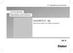
Operating instructions
For the operator
Operating instructions
ecoTEC plus
Gas-fired wall hung high efficiency boiler
GB, IE
Inhaltsverzeichnis
Inhaltsverzeichnis
1
1.1
1.2
1.3
1.4
1.5
Notes on the documentation ..................................... 3
Storing documents .......................................................... 3
Symbols used .................................................................... 3
Applicability of the instructions ................................... 3
Identification plate........................................................... 3
CE label............................................................................... 3
2
2.1
2.1.1
2.1.2
2.2
2.3
Safety .................................................................................5
Safety and warning information ..................................5
Classification of warnings ..............................................5
Structure of warnings .....................................................5
Intended use......................................................................5
Basic safety instructions ................................................6
3
3.1
3.2
3.2.1
3.2.2
Description of devices and functions ......................8
Design .................................................................................8
Function ..............................................................................8
Heating mode....................................................................8
Hot water production with domestic hot water
cylinder (VU boiler) .........................................................8
Hot water production with VUW boiler ......................8
Hot water production with VUI boiler/VUW boiler
with actoSTOR ..................................................................9
3.2.3
3.2.4
4
4.1
4.2
4.3
4.4
4.5
Operation ........................................................................ 10
Overview of the control elements ............................. 10
Digital Information and Analysis System (DIA) ...... 10
Operating concept ...........................................................11
Basic display.....................................................................12
Operating levels ..............................................................12
5
5.1
5.1.1
5.1.2
5.1.3
5.1.4
5.2
5.2.1
Operation .........................................................................13
Putting the boiler into service. ....................................13
Opening/closing the isolator devices .........................13
Switching on the boiler..................................................13
Checking the fill level of the heating system ...........14
Filling the heating system ...........................................14
Setting the heating flow temperature .......................15
Setting the heating flow temperature without a
controller connected ......................................................15
Using a controller to set the heating flow
temperature .....................................................................15
Hot water production with VUW boilers ...................15
Setting the hot water temperature ............................16
Activating/deactivating Comfort mode .....................16
Setting the cylinder charging mode
(VUI 937 only) ..................................................................16
Hot water production with VU boilers .......................17
Setting a room thermostat or weather
compensator ................................................................... 18
Switching off the functions of the boiler ................. 18
Switching off hot water production (VU boiler) ..... 18
Switching off Heating mode (summer mode) ......... 18
Temporarily shutting down the boiler .......................19
5.2.2
5.3
5.3.1
5.3.2
5.3.3
5.4
5.5
5.6
5.6.1
5.6.2
5.7
2
5.8
5.8.1
5.8.2
Protecting the heating system against frost ...........19
Activating the frost protection function ...................19
Draining the heating system ........................................19
6
Energy saving tips ...................................................... 20
7
7.1
7.2
7.3
7.4
7.5
Troubleshooting ............................................................22
Reading fault messages ...............................................22
Detecting and rectifying malfunctions .....................23
Rectifying a water shortage ........................................23
Resolving ignition faults ...............................................24
Maintenance message ..................................................24
8
8.1
8.1.1
8.1.2
8.2
Additional functions....................................................25
Operation in the menu..................................................25
Structure of the menu ..................................................25
Overview of menu structure .......................................26
Displaying Live monitor (current status of the
boiler) ................................................................................27
Setting the display contrast ........................................27
Setting the language.....................................................27
Displaying contact data for the competent
person ...............................................................................28
Displaying the serial number and article number .28
Reset burner off time (resetting burner
anti-cycling time) ...........................................................28
8.3
8.4
8.5
8.6
8.7
9
9.1
9.2
Service .............................................................................29
Servicing the boiler .......................................................29
Caring for your boiler ...................................................29
10
10.1
10.2
Decommissioning ........................................................ 30
Disposing of the boiler ................................................ 30
Disposing of the packaging ........................................ 30
11
11.1
11.2
Manufacturer's guarantee and works customer
services ............................................................................31
Factory guarantee...........................................................31
Vaillant Service ................................................................31
12
Glossary ..........................................................................32
Index
33
Brief operating instructions ....................................................35
Operating instructions ecoTEC plus 0020116701_00
Notes on the documentation
1
Notes on the documentation
The following instructions are intended to guide you
throughout the entire documentation. Other documents
apply in addition to these operating instructions.
We accept no liability for any damage caused by failure to
observe these manuals.
1.3
Applicability of the instructions
These operating instructions apply exclusively to appliances
with the following article numbers:
Boiler
Type designation
Article number
ecoTEC plus
VU GB 612/5-5
0010011677
ecoTEC plus
VU GB 615/5-5
0010011678
ecoTEC plus
VU GB 618/5-5
0010011679
ecoTEC plus
VU GB 618/5-5 (LPG)
0010011680
Further instructions for all accessories and controllers used
also apply.
The benchmark check list for starting up gas-fired boilers
(contained in the installation instructions) must be completed by the competent person present during the commissioning and must be passed on to the system operator.
After reading through these instructions, if you have any
questions regarding the operation of the boiler, please contact your recognised approved heating specialist company
or Vaillant's technical department.
ecoTEC plus
VU GB 624/5-5
0010011681
ecoTEC plus
VU GB 630/5-5
0010011682
ecoTEC plus
VU GB 630/5-5 (LPG)
0010011683
ecoTEC plus
VU GB 637/5-5
0010011684
ecoTEC plus
VUW GB 824/5-5
0010011685
ecoTEC plus
VUW GB 831/5-5
0010011686
ecoTEC plus
VUW GB 831/5-5 (LPG)
0010011687
In these instructions, the heating specialist company and
competent person approved by the Health and Safety Executive will be abbreviated as the heating specialist company
and competent person.
ecoTEC plus
VUW GB 837/5-5
0010011688
ecoTEC plus
VUI GB 937/5-5
0010011691
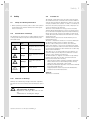
1.1 Type overview
1.1
To find out the article number of your boiler, refer to the
identification plate.
Other applicable documents
When operating the ecoTEC plus, you must observe all
operating instructions that are included with other components of your system.
Storing documents
> Store these operating instructions and all other applicable documents in such a way that they are available
whenever required.
> If you move out or sell the house, pass on the documents
to the next occupant as well.
1.2
Symbols used
The symbols used in the text are explained below: Symbols
for identifying dangers are also used in these operating
instructions (¬ Section 2.1.1).
i
>
Symbol that denotes useful tips and information
Symbol for a required action
Operating instructions ecoTEC plus 0020116701_00
1
1.4
Identification plate
The identification plate of your Vaillant ecoTEC plus boiler
is attached at the factory to the underside of your boiler.
The seventh to sixteenth digits of the serial number on the
identification plate represent the article number.
The serial numbers are also located on a plate, which is
stuck behind the front flap on the underside of the boiler in
a plastic fish plate (¬ Fig. 3.1 Item 2). You can also view the
serial number in the display of the boiler (¬ Section 8.6 ).
1.5
CE label
The CE label shows that the boilers comply
with the basic requirements of the applicable
directives as stated on the identification plate.
3
1
Notes on the documentation
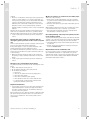
i
4
Vaillant Ltd. supports the Benchmark Initiative.
A benchmark check-list for commissioning gasfired boilers is attached to these installation
instructions. It is very important that this document be filled out properly when installing, commissioning and handing-over to the system operator.
Operating instructions ecoTEC plus 0020116701_00
a
Safety 2
2
Safety
2.1
2.2
Safety and warning information
> When operating your boiler, take account of the general
safety instructions and the warning notes that appear
before each action.
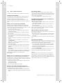
2.1.1
Classification of warnings
The warnings are classified in accordance with the severity
of the possible danger using the following warning signs
and signal words:
Warning sign
a
e
a
b
Signal
word
Danger!
Explanation
Immediate danger to life or
risk of
severe personal injury
Danger!
Risk of death from electric
shock
Warning!
Risk of minor personal
injury
Caution!
Risk of material or environmental damage
2.1 Meaning of warning signs and signal words
Intended use
The Vaillant ecoTEC plus boilers are state-of-the-art appliances which have been constructed in accordance with recognised safety regulations. Nevertheless, there is still a risk
of injury or death to the operator or others or of damage to
the boiler and other property in the event of improper use
or use for which it is not intended.
This boiler is not intended for use by persons (including
children) having limited physical, sensory or mental capacities or who have inadequate experience and/or knowledge,
unless supervised by a person responsible for their safety
or who has been given instructions from them as to how to
operate the boiler.
Children must be supervised to ensure that they do not
play with the boiler.
The boiler is intended as a heater for closed hot water/central heating systems and for hot water generation.
The use of the ecoTEC plus in vehicles, such as mobile
homes and caravans, is not classed as intended use. Units
that are not classed as vehicles are those that are installed
in a fixed and permanent location and that do not have any
wheels (fixed installation).
Any other use, or use beyond that specified, shall be considered as improper use. Any direct commercial or industrial use is also deemed to be improper.
The manufacturer or supplier is not liable for any damage
resulting from such use. The user alone bears the risk.
Intended use includes the following:
– observing the included operating, installation and maintenance instructions for the Vaillant product and any
other parts and components of the system
– installing and fitting the appliance in accordance with the
boiler and system approval
– complying with all of the inspection and maintenance
conditions listed in the instructions.
Caution!
Any misuse is forbidden.
2.1.2
Structure of warnings
Warnings are identified by an upper and lower separating
line and are laid out according to the following basic principle:
a
Signal word!
Type and source of danger!
Explanation of the type and source of danger
> Measures for averting the danger
Operating instructions ecoTEC plus 0020116701_00
5
a
a
a
2 Safety
2.3
Basic safety instructions
> Observe the following safety instructions at all times.
Installation and settings
The boiler must only be installed by a suitably qualified
competent person. The existing regulations, rules and
guidelines must be observed when doing so.
He is also responsible for inspection, maintenance and
repairs to the boiler, and alterations to the gas volume setting.
What to do if you smell gas in buildings
Installation errors, damage, handling, an unauthorised
installation site or similar can cause gas to escape and
result in a risk of poisoning and explosion. If there is a smell
of gas in the building, proceed as follows:
> Avoid rooms that smell of gas.
> If possible, open doors and windows fully and ensure
adequate ventilation.
> Avoid the use of naked flames (e.g. lighters, matches).
> Do not smoke.
> Do not use any electrical switches, mains plugs, doorbells, telephones or other intercommunication systems in
the building.
> Close the gas meter isolator device or the main isolator
device.
> If possible, close the gas isolator cock on the boiler
(¬ Section 5.1.1).
> Warn other occupants in the building by calling out or
banging on doors or walls.
> Leave the building.
> If you can actually hear gas leaking, leave the building
immediately and ensure that others do not enter the
building.
> Alert the police and fire brigade once you are outside
the building.
> Use a telephone outside the building to inform the emergency service department of the gas supply company.
National phone number for gas emergencies:
0800 111 999
What to do in an emergency if you smell flue gas
Installation errors, damage, handling, an unauthorised
installation site or similar can cause flue gas to escape and
result in a risk of poisoning. If there is a smell of flue gas in
the building, proceed as follows:
> Open all accessible doors and windows fully and ensure
adequate ventilation.
> Switch the boiler OFF.
> Inform a heating specialist company.
Preventing scalding
There is a danger of scalding at the hot water draw-off
points if the hot water temperatures are greater than 60 °C.
Young children and elderly persons are particularly at risk,
even at lower temperatures.
> Select the temperature so that nobody is at risk.
Preventing material damage due to unauthorised
changes to the appliance.
Take note of the following:
> Never interfere or tamper with the boiler or other parts
of the heating system.
> Never try to carry out maintenance work or repairs on
the boiler yourself.
> Do not damage or remove any seals on components.
Only recognised heating specialist companies are authorised to alter sealed components.
Material damage caused by corrosion
To prevent corrosion on the boiler and also on the flue system, note the following:
> Do not use sprays, solvents, chlorinated cleaning agents,
paint, adhesives or similar substances in the vicinity of
the boiler.
These substances can cause corrosion, even in the flue system.
Preventing frost damage
If there is a power cut, or if the room temperature is set too
low in individual rooms, it cannot be ruled out that sections
of the heating system might be damaged by frost.
> If you are going to be away during a cold period, make
sure the heating system remains in operation and that
the rooms are sufficiently heated.
> Always observe the information on frost protection provided in ¬ Section 5.8.
Even if rooms, or the whole dwelling, are not in use for certain periods, the heating must remain in operation.
Caution!
Frost protection and monitoring devices are only active
while the boiler is connected up to the power supply. The
boiler must be connected to the power supply. The boiler
must be switched on. You can see from symbols and/or text
in the display that the boiler is switched on.
Explosives and highly flammable substances
The risk of explosion arises from the flammable mixture of
gas and air. Take note of the following:
> Do not use or store explosive or highly flammable substances (e.g. petrol, paper, paint) in the same room as the
boiler.
6
Operating instructions ecoTEC plus 0020116701_00
a
Safety 2
Caution!
> Under no circumstances should you add frost protection
agents (or other additives, e.g. jointing compounds, corrosion protection agents, etc.) to the heating water without first consulting your qualified competent person.
Otherwise, this could result in damage to seals and diaphragms as well as noises during heating operation.
Vaillant assumes no liability for this or any consequential
damage.
Another way to protect the heating system and the boiler
from frost is to drain them. In doing so, you must ensure
that the heating system and boiler are completely drained.
> Contact your approved heating specialist company for
advice.
Keeping the boiler ready for operation with an
emergency power generator in the event of a power
cut
Your recognised heating specialist company connected your
boiler to the power mains during installation.
If the power supply is cut, it is possible that parts of the
heating system may become damaged by frost.
If you want to maintain the operation of the boiler during a
power cut using an emergency power generator, take note
of the following:
> Make sure that the technical values of this generator
(frequency, voltage, earthing) match those of the power
mains.
> Contact your approved heating specialist company for
advice.
What to do if there are leaks in the hot water pipes
Take note of the following:
> In the event of leaks, immediately close the cold water
stop valve in the hot water pipework between the boiler
and the draw-off points.
> Have the leak repaired by your approved heating specialist company.
With Vaillant ecoTEC plus boilers, the cold water stop valve
is not included in the scope of delivery of your boiler.
> Ask your approved heating specialist company where
they fitted the cold water stop valve.
Preventing damage caused by low system pressure
in the heating system
To prevent the heating system being used when the amount
of water is too low and to therefore prevent any subsequent
damage that may be caused by this, note the following:
> Check the filling pressure of the heating system at regular intervals.
> Always observe the information on filling pressure provided in ¬ Section 5.1.3.
Requirements for the installation site
It is not necessary to keep a clearance between the boiler
and combustible materials or components since, at the
nominal heat output of your boiler, the temperature on the
surface of the casing is always lower than the maximum
permissible temperature of 85 °C.
Changes to the surroundings of the boiler
You must not make any changes to the surroundings of the
boiler:
> Never shut down the safety devices.
> Do not tamper with any of the safety devices.
> Do not make any changes:
– to the boiler
– to the gas, air, water and electricity supply lines,
– to the entire flue system,
– to the entire condensate drain system,
– to the expansion relief valve or the drain line and
– to constructional conditions that could affect the
operational reliability of the boiler.
Cupboard Installation
> If you require your boiler to be fitted into a kitchen type
cupboard then please consult your approved heating
specialist company. Under no circumstances must you
enclose your boiler yourself.
Enclosing the boiler in a cupboard requires compliance with
the special design instructions. This is to ensure all necessary access is available for all necessary future service
requirements.
Operating instructions ecoTEC plus 0020116701_00
7
a
3 Description of devices and functions
3
3.1
Description of devices and functions
3.2
Function
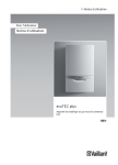
Your Vaillant ecoTEC plus is a gas-fired wall hung high efficiency boiler, which generates heat for heating and/or hot
water production.
VU boilers can be operated together with a domestic hot
water cylinder, which stores a larger volume of hot water.
VUI boilers are fitted with internal hot water production and
a domestic hot water cylinder to achieve increased hot
water convenience.
Design
3.2.1
Heating mode
In heating mode, the boiler heats the hot water and sends it
through the radiators or underfloor heating of your home
(heating circuit). The hot water pumped into the heating circuit exits the boiler at a specific heating flow temperature,
emits its heat into the rooms and flows back into the boiler
once cooled to return temperature. The heating water is
then heated again.
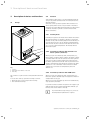
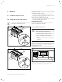
1
2
3.2.2 Hot water production with domestic hot
water cylinder (VU boiler)
3
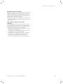
3.1 Front view of the ecoTEC plus (VU and VUW boiler)
Key
1 Controls
2 Plate with serial number on the rear
3 Front flap
The controls for your boiler are arranged behind the front
flap.
To access the controls, open the front flap as follows:
> Reach into the recessed grip in the front flap.
> Fold down the front flap.
When you open a hot water tap (sink, shower, bath, etc.),
the hot water is taken from the domestic hot water cylinder.
Cold water than flows into the domestic hot water cylinder
in its place. If the hot water temperature in the domestic
hot water cylinder falls below the value set, then the boiler
operates automatically and reheats the domestic hot water
cylinder. As soon as the water in the domestic hot water
cylinder has received the set temperature, the boiler
switches off.
3.2.3 Hot water production with VUW boiler
When you open a hot water tap (sink, shower, bath, etc.),
the boiler operates automatically and supplies hot water at
a temperature set by you.
When you close the hot water tap. the boiler automatically
stops producing hot water.
If you have activated Comfort mode, the boiler supplies you
with hot water at the requested temperature without you
having to wait for the water to heat up.
i
8
To prevent unnecessary energy loss, do not set
the temperature higher than is required.
Operating instructions ecoTEC plus 0020116701_00
Description of devices and functions 3
3.2.4 Hot water production with VUI boiler
The hot water production with additional stratified cylinder
functions in the same way as on the VUW boiler (¬ Section 3.2.3).
In addition, you can activate the heating of the stratified
cylinder by switching on Comfort mode. This uses special
charging technology to ensure that you have a similar hot
water convenience as you would get with a much bigger
conventional domestic hot water cylinder. You immediately
get hot water at the required temperature without having
to wait for the water to heat up and you have a larger hot
water volume at your disposal.
Operating instructions ecoTEC plus 0020116701_00
9
4 Operation
4
Operation
4.1
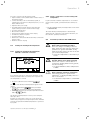
Overview of the control elements
F.01
5
8
7
50
1
2
3
6
4
4
3
2
1
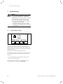
4.1 ecoTEC plus control elements
1
On/off button for switching the boiler on or off
2
Controller (accessory)
The Digital Information and Analysis System consists
of:
3
Reset button to clear certain faults
4
Operating buttons
5
Display
4.2
Digital Information and Analysis System
(DIA)
The ecoTEC plus boiler is equipped with a digital information and analysis system (DIA system). It consists of a display showing symbols and plain text, along with 5 operation
buttons. This system pro vides information on the operating status of your boiler and helps you deal with problems.
The display lights up,
– if you switch the boiler on or
– if you press a button for the DIA system when it is
switched on. At first, pressing this button does not trigger any other function.
The light automatically switches off after one minute if you
do not press any button.
10
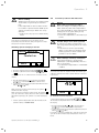
5
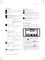
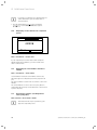
4.2 DIA system with possible symbol displays
1
Display indicating the current heating flow temperature, the filling pressure of the heating system, the
operating mode, a fault code or other additional
information in plain text
2
Display of the current configuration of the right-hand
selection button (after switching on the boiler and in
the basic display: = heating)
3
Left and right-hand selection buttons
4
Minus and plus button
5
Chimney sweep mode (for chimney sweeps only)
6
Access to the menu for additional information
7
Display of the current configuration of the left-hand
selection button (after switching on the boiler and in
= hot water production)
the basic display:
8
Display of the symbols for the active operating status
Operating instructions ecoTEC plus 0020116701_00
Operation 4
Displayed symbols
Flame:
Permanently on:
Additional symbols:
Summer mode active
Heating mode is switched off
Correct burner operation; Burner on
Display of the current burner modulation rate (bar
graph display)
Boiler anti-cycling time is active
This function is used to prevent frequent on/off
operations, and therefore contributes to prolonging
the life of your boiler.
The symbol also appears if the boiler is in a waiting
period.
Display of the current filling pressure of the heating
system (bar graph display).
The filling pressure must be in the mid range
between the two dotted lines.
Permanently on: The filling pressure is within the
permitted range.
Flashing:
F.XX
Fault in the boiler. Appears instead of the basic display (¬ Section 4.4).
A plain text display explains the displayed fault
code.
Example: F.10 Flow NTC short circuit.
The filling pressure is outside of
the permitted range (¬ Section 5.1.3).
4.3
Operating concept
Heating mode active
Permanently on: Heat demand, heating mode
Flashing:
Burner on in heating mode
You can operate the boiler using the selection buttons and
the plus/minus buttons.
Both selection buttons have a soft key function. This means
that their function can change.
DHW temperature
Hot water generation active
45
For VUI/VUW boilers:
Permanently on: In draw-off mode before the
burner is on
Flashing:
Burner on in draw-off mode
On VU boilers:
Permanently on: time slot activated for hot water
generation
Flashing:
Domestic hot water cylinder is
being heated, burner on
Only on VUI/VUW boilers:
Comfort mode active
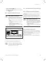
Back
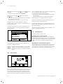
4.3 Display after pressing the left-hand selection button
If, for example, you press the left-hand selection button in
the basic display (¬ Section 4.4), the current function
" (hot water temperature) to "Back".
switches from "
:
With the left-hand selection button
– you can navigate directly to set the hot water temperature
– you can cancel the change to a set value or the activation of an operating mode
– you can go one selection level higher in the menu
Permanently on: Comfort mode is activated
Flashing:
Comfort mode is active,
burner on
Service required. In the "Live monitor", you can
read further information about the reason for the
service (¬ Section 8.2).
Operating instructions ecoTEC plus 0020116701_00
:
With the right-hand selection button
– you can navigate directly to set the heating flow temperature, to the precise value of the water pressure of the
heating system and to activate Comfort mode
– you can confirm a set value or the activation of an operating mode
– you can go one selection level lower in the menu
11
4 Operation
With both selection buttons
+
same time:
– you can navigate to the menu (¬ Section 8)
at the
or the plus button
With the minus button
:
– you can go back and forth between the individual points
of the entry list in the menu
– you can increase or decrease a selected set value
Adjustable values are always displayed as flashing.
You must always confirm a change to a value. Only then is
the new setting saved.
You always have the option to cancel the change to a setting or the reading of a value by pressing the left-hand
selection button.
Menu
Water pressure
Live Monitor
Information
Back
Select
4.4 Selecting a list entry in the menu
A highlighted object is indicated in the display inversely
(light text on dark background).
i
4.4
If you do not press any buttons for more than
15 minutes, the display returns to the basic display. Changes that are not confirmed will not be
applied.
press of the button. In this case, to trigger the button function, you must press the button again.
You can switch back to the basic display by:
– pressing the left-hand selection button and exiting the
selection levels
– not pressing any button for longer than 15 minutes.
Changes that are not confirmed will not be applied.
If there is a fault message, the basic display switches to a
plain text display of the fault message.
From the basic display, you can directly change and read
the most important settings and information by pressing
the selection buttons.
The functions that are available depend on whether a controller is connected to the boiler.
4.5
Operating levels
The boiler has two operating levels.
Operating levels for the operator
The operating level for the operator offers you the most
frequently used setting options that do not require any special prior knowledge and displays the most important information. You can access additional information using a
menu.
Operating level for the heating engineer
The operating level for the heating engineer must only be
operated with expertise and is therefore protected by a
code. This level is used by the competent person to adjust
the parameters for the boiler to the heating system.
Basic display
50
4.5 Basic display
In the normal operating status, you can see the basic display in the display. The basic display shows the current status of the boiler. If you press a selection button, the relevant activated function is displayed in the display. If the display becomes dark, the light is first switched on by the first
12
Operating instructions ecoTEC plus 0020116701_00
Operation 5
5
Operation
5.1
Putting the boiler into service.
5.1.1
Opening/closing the isolator devices
The isolator devices are open if the slot for the screwdriver
is parallel to the pipes.
> Open the gas isolator cock (3.
> Check that the heating flow (4) and heating return (1)
isolator devices are open. Open these if they are closed.
For the unit version VUW and VUI:
> Also open the cold water stop valve (2).
> In order to check this, open a hot water tap at a draw-off
point and check that water flows out.
Closing isolator devices
i
If the boiler is fitted with a bottom cover, the isolating devices are under this cover.
The isolator devices are closed if the slot for the screwdriver is at a right-angle to the pipes.
5.1.2
2
Switching on the boiler
1
b
4
3
Caution!
Risk of damage caused by frost.
Frost protection and monitoring devices are
only active while the boiler is connected up
to the power supply and your boiler is
switched on using the on/off switch.
> Do not isolate the boiler from the power
mains.
> Leave your boiler switched on at the on/
off switch.
90°
To ensure that the frost protection and monitoring devices
remain active, switch your boiler on and off using the controller (see the corresponding operating instructions for
more information on this).
¬ Section 10 describes how to fully shut down your boiler.
5.1 Opening the isolator devices on the VUW boiler
2
1
50
4
3
1
5.3 Switching on the boiler
90°
> Press the on/off switch (1) to switch on the boiler.
5.2 Opening the isolator devices on the VU boiler
Operating instructions ecoTEC plus 0020116701_00
13
5 Operation
If the boiler is switched on, the current heating flow temperature and other information will appear in the display (2)
(¬ Fig. 4.5).
You can see the filling pressure in the right-hand bar graph
display or display the exact value using the selection buttons to the right of the display.
To set your boiler to suit your needs, read ¬ Section 5.2 to
Section 5.4 which describe the setting options for hot
water production and the heating mode.
Water pressure
1,0
3
5.1.3
Checking the fill level of the heating system
b
Caution!
Low filling pressure can cause damage to
the unit.
Operating the heating system with low filling pressure can cause damage to the
boiler and the heating system. The boiler
switches off automatically when the filling
pressure falls too low.
> Fill up the heating system as soon as the
filling pressure falls below 0.08 MPa
(0.8 bar).
0,8
If the heating system extends over several storeys, a higher
filling pressure may be required for the heating system.
> Ask your approved competent person for details about
this.
If the pressure falls below 0.08 MPa (0.8 bar), the righthand bar graph display and the current pressure flash in
the display.
> Fill up the heating system (¬ Section 5.1.4).
i
Switch off the boiler if the filling pressure in the
heating system falls below 0.05 MPa (0.5 bar).
The display alternates between the fault message F.22 and the current filling pressure.
The heating system must be topped up with water before
the boiler can be put into operation again. As soon as the
system has been topped up with sufficient water, the message disappears automatically after approx. 20 seconds. If
the pressure drops frequently the reason for the loss of hot
water must be identified and eliminated
> Contact your heating engineer.
14
2
3,0
Back
5.4 Digital display of filling pressure
> Press the right-hand selection button
twice.
The current filling pressure (1) and the minimum (3) or
maximum water pressure (2) that is to be set appear in the
display.
5.1.4
To avoid operating the system with insufficient water and to
prevent possible damage associated with this, your boiler is
fitted with a pressure sensor and a digital pressure display.
To ensure that the heating system operates smoothly, the
filling pressure when the heating system is cold must be
between 0.1 MPa and 0.2 MPa (1.0 bar and 2.0 bar) or lie
between the two dotted lines in the bar graph display.
1
Filling the heating system
b
Caution!
Risk of damage caused by tap water that
is extremely calciferous or corrosive or
contaminated by chemicals.
Unsuitable tap water damages the seals
and diaphragms, blocks components in the
boiler and heating system through which
the water flows and causes noise.
> Only fill the heating system with suitable
tap water.
> In case of doubt, consult your approved
competent person regarding this.
To fill up and to refill the heating system, you can normally
use tap water. In exceptional cases, however, the water quality may not be suitable for filling the heating system
because the water is highly corrosive or calciferous.
> If this is the case, contact your approved heating engineer.
The heating system is filled via a filling cock provided by
the installer.
> Ask your approved competent person where the filling
cock is located.
> Ask your approved competent person to explain how to
fill the heating system.
You can show the exact filling pressure in the display
(¬Section 5.1.3).
Operating instructions ecoTEC plus 0020116701_00
Operation 5
Proceed as follows to fill the heating system:
> Open all radiator valves (thermostatic radiator valves) of
the heating system.
> Connect the filling cock for the heating system, as
explained by your approved competent person, to a cold
water draw-off valve.
> Open the filling cock slowly.
> Fill it with water using the draw-off valve until the
required filling pressure is reached in the display.
> Close the draw-off valve.
> Bleed all the radiators.
> Then check the filling pressure on the display.
> Fill with more water if required.
> Close the filling cock.
> Remove the connection between the filling cock and the
draw-off valve.
> Return to the basic display.
5.2
Setting the heating flow temperature
5.2.1
Setting the heating flow temperature
without a controller connected
Target flow temp.
60
Back
5.5 Setting the heating flow temperature
If no external controller is connected to the boiler, set the
heating flow temperature according to the respective outside temperature as follows:
5.2.2 Using a controller to set the heating flow
temperature
If your boiler has a weather compensator or a room thermostat control system, you must make the following settings:
> Set the maximum heating flow temperature on the boiler
(¬ Section 5.2.1).
The actual heating flow temperature is automatically
adjusted by the controller (for information about this, see
the controller operating instructions).
5.3
Hot water production with VUW boilers
a
Danger!
Risk of being scalded by hot water.
There is a danger of scalding at the hot
water draw-off points if the hot water temperatures are greater than 60°C. Young
children and the elderly can even be at danger at lower temperatures.
> Select the temperature so that nobody is
at risk.
a
Danger!
Possible danger to life from legionella!
If the boiler is used to reheat water in a
solar-based drinking water heating system,
note the following:
> Set the minimum hot water temperature
to 60°C.
b
Caution!
Risk of damage caused by calcification.
If the water hardness is greater than
3.57 mol/m3 (= 357 mg/l CaCO3), there is a
risk of calcification.
> Set the water temperature to a maximum
of 50°C.
> Press the right-hand selection button
(" ").
The value of the heating flow temperature appears in the
display.
or the plus button
> Use the minus button
to change the heating flow temperature.
> Confirm the change by pressing the right-hand selection
("OK").
button
The heating flow temperature is factory-set for temperatures up to 75°C.
If higher (or lower) values can be set on your boiler, this
means that your approved competent person has calibrated
your unit to adjust the maximum temperature to your heating system.
Operating instructions ecoTEC plus 0020116701_00
15
5 Operation
5.3.1
> Press the right-hand selection button
").
("
"Comfort mode on" or "Comfort mode off" flashes in the
display.
Setting the hot water temperature
DHW temperature
45
or the plus button
> Use the minus button
to activate or deactivate the comfort mode.
> Confirm the change by pressing the right-hand selection
("OK").
button
5.6 Setting the hot water temperature
When you have activated Comfort mode, the symbol " " is
shown in the basic display.
When you have deactivated Comfort mode, the symbol " "
goes out in the basic display.
> Press the left-hand selection button
(" ").
The hot water temperature that is set is shown flashing on
the display.
5.3.3 Setting the cylinder charging mode
(VUI 937 only)
Back
or the plus button
> Use the minus button
to change the hot water temperature.
> Confirm the change by pressing the right-hand selection
("OK").
button
If you have connected an eBUS auto controller to the boiler,
you can set the hot water target temperature on the controller.
> Ask your approved competent person whether an eBUS
auto controller is connected.
If you are using an eBUS auto controller:
> Set the hot water temperature on the boiler to the maximum possible temperature.
> Set the desired hot water temperature (hot water target
temperature) on your controller.
If an additional stratified storage tank is connected, you can
switch cylinder charging on and off using the controller on
your boiler.
"Cylinder charging mode" refers to the process for heating
up the cylinder.
i
Cylinder charging is deactivated ex-works and
must be activated during initial start-up.
The cylinder charging of the layer storage tank is only
active if Comfort mode is switched on.
If Comfort mode is activated, the symbol " " appears in the
display (¬ Section 5.3.2).
When cylinder charging is switched on, the following temperatures can be set for the hot water temperature (¬ Section 5.3.1):
– minimum temperature
– maximum temperature
5.3.2 Activating/deactivating Comfort mode
Comfort mode immediately supplies you with hot water at
the required temperature, without you having to wait for
the water to heat up. To do this, the plate-type heat
exchanger of the ecoTEC plus is kept at your selected temperature level.
Comfort operation
50 °C
65 °C
When cylinder charging is switched off, the following temperatures can be set for the hot water temperature (¬ Section 5.3.1):
– minimum temperature
– maximum temperature
35 °C
65 °C
If cylinder charging is switched off, the storage tank is not
held at temperature. If you draw off the water, the boiler
switches on and, in this case, only operates on the throughflow principle.
Comfort on
Back
5.7 Switching Comfort mode on and off
> Press the left-hand selection button
16
("
").
Operating instructions ecoTEC plus 0020116701_00
Operation 5
a
Danger!
Risk of scalding.
VUI 937 only: The boilers are equipped with
an automatic Legionella protection function:
If the temperature in the hot water domestic hot water cylinder falls below 50 °C, the
cylinder is heated up to 70 °C once every
24 hours.
> If this is the case, try not to draw off any
water.
Your approved competent person can switch off the
Legionella protection function. Ask your approved competent person for details about this.
5.4
Hot water production with VU boilers
a
Danger!
Risk of being scalded by hot water.
There is a danger of scalding at the hot
water draw-off points if the temperatures
are greater than 60 °C. Young children and
elderly persons are particularly at risk,
even at lower temperatures.
> Select the temperature so that nobody is
at risk.
a
Danger!
Possible danger to life from legionella!
In domestic hot water cylinders there is a
risk of legionella forming, which can causes
illness.
> If the boiler is used for post-heating
within a solar-supported drinking water
heating system, set the hot water temperature to at least 60 °C.
b
Caution!
Risk of damage caused by calcification.
If the water hardness is greater than
3.57 mol/m3 (= 357 mg/l CaCO3), there is a
risk of calcification.
> Set the water temperature to a maximum
of 50 °C.
Switching cylinder charging on and off
Comfort operation
Comfort on
Back
5.8 Switching cylinder charging (Comfort mode) on and off
> Press the left-hand selection button
(" ").
> Press the right-hand selection button
").
("
"Comfort mode on" or "Comfort mode off" flashes in the
display.
or the plus button
> Use the minus button
to activate or deactivate Comfort mode.
> Confirm the change by pressing the right-hand selection
("OK").
button
When you have activated Comfort mode, the symbol " " is
shown in the basic display.
When you have deactivated Comfort mode, the symbol " "
goes out in the basic display. The boiler now operates in the
through-flow principle; the cylinder is not held at temperature.
> Set the cylinder temperature using the hot water temperature setting (¬ Section 5.3.1).
To produce hot water in conjunction with the VU unit type,
a VIH-type domestic hot water cylinder must be connected
to the boiler.
DHW temperature
45
Back
5.9 Setting the hot water temperature
> Press the left-hand selection button
(" ").
The hot water temperature that is set is shown flashing on
the display.
or the plus button
> Use the minus button
to change the hot water temperature.
> Confirm the change by pressing the right-hand selection
("OK").
button
If you have connected an eBUS auto controller to the boiler,
you can set the hot water target temperature on the controller.
Operating instructions ecoTEC plus 0020116701_00
17
5 Operation
> Ask your approved competent person whether an eBUS
auto controller is connected.
If you are using an eBUS auto controller:
> Set the hot water temperature on the boiler to the maximum possible temperature.
> Set the desired hot water temperature (hot water target
temperature) on your controller.
DHW temperature
Cylinder charging off
Cancel
5.5
Setting a room thermostat or weather
compensator
Ok
5.11 Switching off cylinder charging
> Press the left-hand selection button
(" ").
The hot water temperature that is set is shown flashing on
the display.
1
to set the hot water
> Use the minus button
temperature to "Cylinder charging off"
> Confirm the change by pressing the right-hand selection
("OK").
button
Cylinder charging is switched off. Only the frost protection
function for the cylinder remains active.
2
5.10 Setting the room temperature controller/weather compensator
> Set the room thermostat, weather compensator (1) and
thermostatic radiator valves (2) as specified in the operating instructions for these accessories.
5.6
Switching off the functions of the boiler
5.6.1
Switching off hot water production (VU
boiler)
To switch the cylinder charging on again:
to set your required hot
> Use the plus button
water temperature.
> Confirm the change by pressing the right-hand selection
("OK").
button
5.6.2 Switching off Heating mode (summer mode)
Target flow temp.
Heating off
Cancel
Ok
5.12 Switching off Heating mode (summer mode)
If a domestic hot water cylinder is connected, you can
switch off the cylinder charging without switching off the
heating mode.
You can switch off the heating mode in summer without
switching off the hot water supply.
(" ").
> Press the right-hand selection button
The value of the heating flow temperature appears in the
display.
to set the hot water
> Use the minus button
flow temperature to "Cylinder charging off".
> Confirm the change by pressing the right-hand selection
("OK").
button
Heating mode is switched off. The symbol appears on the
display.
To switch the heating mode on again:
18
Operating instructions ecoTEC plus 0020116701_00
Operation 5
> Use the plus button
to set your required
heating flow temperature.
> Confirm the change by pressing the right-hand selection
("OK").
button
5.7
Temporarily shutting down the boiler
b
Caution!
Risk of damage caused by frost.
Anti-freeze and monitoring devices are only
active while the boiler is connected up to
the power mains and the on/off switch is
on.
> Do not isolate the boiler from the power
mains.
> Leave your boiler switched on at the on/
off switch.
> Only switch the boiler on and off in normal mode using the controller.
> Make sure that the boiler cannot become
damaged by frost.
5.8
Protecting the heating system against frost
5.8.1
Activating the frost protection function
Your Vaillant ecoTEC plus boiler is fitted with a frost protection function:
If the heating flow temperature falls below 5 °C when the
on/off switch is on, the boiler comes into operation and
heats the heat generation circuit to approx. 30 °C on both
the heating side and the hot water side (if available).
b
Caution!
Risk of damage caused by frost.
The frost protection function cannot guarantee flow through the entire heating system, which means that parts of the heating
system may freeze and become damaged.
> Make sure that the boiler remains on
whilst you are away.
> Make sure that the rooms are heated sufficiently.
2
5.8.2 Draining the heating system
Another way to protect the heating system and the boiler
from frost when they are switched off for a very long time
is to drain them. You must ensure that the heating system
and boiler are completely drained.
All the cold and hot water pipes in the house and in the
boiler must also be drained.
> Ask your heating engineer to drain the heating system.
50
1
5.13 Switching off the boiler
> Press the on/off switch (1) to switch the boiler off.
If the boiler is switched off, the display (2) turns off.
i
If the boiler is going to be unused for longer
periods (e.g. holiday), you should also close the
gas isolator cock and the cold water stop valve,
but only if there is no risk of frost.
Operating instructions ecoTEC plus 0020116701_00
19
6 Energy saving tips
6
Energy saving tips
Fitting a weather compensator
Weather compensators regulate the heating supply temperature according to the outside temperature. Thus it is
ensured that heat in excess of what is required at that
moment is not generated. In addition, desired heating and
set-back phases (e. g. at night) are automatically turned on
and off by using integrated time programmes.
Weather compensators combined with thermostatic radiator valves are the most economical form of heating regulation.
Operating the heating system in energy-saving
mode
> Reducing the room temperature at night and in your
absence.
The simplest and most reliable way is to be able to reduce
the room temperature using the controller with individually
selectable timer programmes.
> At such times, set the room temperature approx. 5 °C
lower than during full heating times.
If the room temperature falls by more than 5 °C, you are
not saving any additional energy because increased heating
capacity would then be required for the next full heating
period. Only for longer absences, e.g. during holidays, is it
worthwhile to further lower the temperatures.
Caution.
> In winter, make sure that adequate frost protection is
maintained (¬ Section 5.8).
Thermostatic radiator valves and weather compensators or room thermostats
Thermostatic valves on all radiators maintain the room temperature exactly once it is set. You can adjust the room
temperature to suit your individual requirements and
ensure effective operation of your heating system using
thermostatic valves in combination with a room thermostat
or a weather compensator.
This is how a thermostatic valve works: If the room temperature rises above the value set on the sensor head, the
thermostatic radiator valve shuts off automatically and
when the temperature drops below the defined value, it
opens again.
Do not obstruct the controller
> Do not obstruct your controller with furniture, curtains
or other objects.
The controller must be able to record the circulating room
air unhindered. Covered thermostatic radiator valves can be
equipped with remote sensors and thus still work.
Ventilating living rooms
> During the heating period, open windows only for ventilation and not for temperature regulation.
A brief ventilation boost is more effective and energy-saving than windows that are kept open for a long time.
Close all the thermostatic valves in the room during ventilation.
> If you have a room thermostat, set it to the minimum
temperature.
This guarantees adequate exchange of air without unnecessary loss of energy and cooling off.
Room temperature
> Set the room temperature only as high as would be
enough for your comfort level.
Each extra degree would cause an increased energy consumption of about 6 %.
> Adjust the room temperature according to the purpose
of use of the room.
For example, normally, bedrooms or rooms that are seldom
used are heated to 20 °C.
Uniform heating
> Heat all of the rooms in your dwelling to the same level
and according to their use.
If you only heat one room or individual rooms in your dwelling, the adjacent unheated rooms will also be heated
through walls, doors, windows, roofs and floors and this
heating will be unregulated. The capacity of the radiators
for the heated rooms is insufficient for this type of operation. The heated rooms are then not heated sufficiently (the
same effect is caused if doors between heated and
unheated rooms (or rooms that are heated to a limited
degree) are left open).
20
Setting the operating mode
> In warmer seasons, when the dwelling needs no heating,
turn the heating to summer mode.
The heating mode is then switched off. The boiler and system remain ready for operation for the hot water production.
Setting the hot water temperature
> Only heat the warm water up to the extent that is necessary for use.
Any further heating results in unnecessary power consumption and hot water temperatures of more than 60 °C also
lead to increased limescale reduction.
Switching on comfort mode (only VUW):
Comfort mode immediately supplies you with hot water at
the required temperature, without you having to wait for
the water to heat up. For this, the hot water heat exchanger
is kept at a preselected temperature level.
If you do not need hot water for a long period, it is recommended to turn off comfort mode to save energy further.
Operating instructions ecoTEC plus 0020116701_00
Energy saving tips 6
Energy-conscious use of water
Energy-conscious use of water can reduce your bills considerably. For example, taking a shower instead of a bath:
whereas about 150 litres of water are required for a bath, a
modern shower equipped with water-saving fittings only
requires a third of this water quantity.
By the way: A dripping water tap wastes up to 2000 litres
of water and a leaking toilet flush wastes up to 4000 litres
of water each year.
Run circulation pumps only if needed
(VU only)
Circulation pumps increase convenience when it comes to
hot water production. But they also need power. And circulating hot water that is not used cools off when passing
through pipes and then needs to be reheated.
> Operate circulation pumps only when hot water is actually needed for the household.
> Use a weather compensator or autotimers to set time
programmes for your circulation pump.
> Or turn on the circulation only for specific needs for a
specific period of time by using a button or switch
installed near a frequently used draw-off point.
> For more information, consult your competent person.
Operating instructions ecoTEC plus 0020116701_00
21
7 Troubleshooting
7
Troubleshooting
a
7.1
Danger!
Risk of injury and material damage due
to incorrect maintenance and repairs.
If maintenance is not carried out, or carried
out incorrectly, this may adversely affect
the operational reliability of your boiler.
> Never perform maintenance or repairs
on your boiler by yourself.
> You must employ an approved competent person or Vaillant Service Solutions
(0870 6060 777) to complete such work.
Reading fault messages
F.75
Fault
Pump water shortage
7.1 Fault display
Fault messages have priority over all other displays. If a
fault develops in the boiler, the display shows a fault code
instead of the basic display. A plain text display explains the
displayed fault code.
Example for F.75: "Fault Pump water shortage".
If multiple faults occur at the same time, the display shows
the corresponding fault codes for two seconds each in
sequence.
> If your boiler displays a fault message, contact your
approved competent person.
You can use the "Live monitor" to call status messages
about the status of your boiler (¬ Section 8.2).
22
Operating instructions ecoTEC plus 0020116701_00
Troubleshooting 7
7.2
Detecting and rectifying malfunctions
If problems occur whilst operating your boiler, you can
carry out the following self-checks:
Problem
No hot water, heating stays
cold;
Boiler does not start
DHW mode without any problems;
Heating does not start:
Possible cause
Solution
Building gas isolator cock closed
> Open building gas isolator cock (¬ Section 5.1.1)
Building power supply switched off
> Switch on building power supply
On/off switch on boiler switched off
> Switch on the on/off switch on the
boiler(¬ Section 5.1.2)
The heating flow temperature is set too low or in the
"Heating off" position (¬ Section 5.6.2) and/or the
hot water temperature is too low
> Set the heating flow temperature to the
desired temperature (¬ Section 5.2) and/or
set the hot water temperature to the desired
temperature (¬ Section 5.3.1 and 5.4)
Filling pressure of the heating system too low
> Top up the heating system with water
(¬ Section 5.1.4)
Air in the heating system
> Purge the radiators.
> If the problem occurs again:
Contact your heating engineer
Ignition malfunction
> Press the reset button
> If the problem occurs again:
Contact your competent person (¬ Section 7.4)
No heating demand via the controller
> Check the timer programme on the controller and correct it if necessary.
> Check the room temperature and, if
required, correct the target room temperature
(¬ Section 5.5; ¬ Controller operating
instructions).
7.1 Detecting and rectifying malfunctions
> If, after checking the points mentioned in Tab. 7.1, your
boiler still shows signs of a fault, contact your approved
competent person to troubleshoot the problem.
7.3
Rectifying a water shortage
0,7
bar
7.2 Display of the filling pressure for the heating system is too
low
If the filling pressure for the heating system falls below
0.08 MPa (0.8 bar), the right-hand bar display and the current filling pressure flash in the display.
Operating instructions ecoTEC plus 0020116701_00
23
7 Troubleshooting
In addition, the maintenance symbol (open-ended spanner)
is displayed after approx. one minute.
If the filling pressure falls below 0.05 MPa (0.5 bar), the
boiler switches off and the fault message F.22 appears in
the display. To put the boiler into operation again, you must
fill the heating system with water (¬ Section 5.1.3 and
5.1.4).
The boiler will only ignite automatically again once you
have reset it manually.
> To reset the boiler manually, press the reset button (3)
and hold for one second.
> If you are unable to resolve the ignition problem yourself
by resetting the boiler three times, then consult your
approved competent person.
7.4
7.5
Resolving ignition faults
b
Maintenance message
Caution!
Risk of damage due to improper modifications.
Improper alterations or persistent faults
can result in material damage.
> If you are unable to resolve the ignition
problem yourself by resetting the boiler
three times, then consult your approved
competent person.
58
7.4 Maintenance message
1
F.28
Failure in start up
Igntn unsuccessful
2
If the open-ended spanner is displayed, a service is required
for the boiler.
> Consult your skilled tradesman about doing this.
The boiler is not in fault mode but continues to operate.
> In the "Live monitor", you can read further information
about the reason for the service (¬ Section 8.2).
i
If the water pressure is shown flashing at the
same time (¬ Section 7.3), you only have to top
up the water (¬ Section 5.1.3 and 5.1.4).
Menu
3
7.3 Resetting the boiler
If the burner fails to ignite after five attempts, the boiler
will not operate and switches to "Fault". This is indicated by
the fault code F.28 or F.29 (1) and a corresponding plain text
display on the display, e.g. for F.28. "Failure during starting,
ignition unsuccessful" (2).
24
Operating instructions ecoTEC plus 0020116701_00
Additional functions 8
8
Additional functions
The digital information and analysis system provides you
with further functions via the menu.
8.1
Operation in the menu
You can access this menu by pressing both selection buttons ("i") at the same time.
8.1.1
Structure of the menu
In addition to the direct operation via the selection buttons
from the basic menu, the digital information and analysis
system has a menu that, in turn, has two selection levels
(sublevels).
Through the selection levels, you navigate to the display
and setting levels in which you can read or change settings.
The selection levels have four display fields.
4
3
Menu
Water pressure
Live Monitor
Information
Back
1
Select
2
8.1 Display fields in the menu
Key
1 Scroll bar (only if there are more list entries than can be shown
at once on the display)
2 Current functions of the right and left-hand selection buttons
(soft key functions)
3 List entries for the selection levels
4 Name of the selection level
i
Path details at the start of an instruction on how
to access this function are provided at the start,
e. g. Menu ¬ Information ¬ Contact data.
Operating instructions ecoTEC plus 0020116701_00
25
8 Additional functions
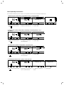
8.1.2
Overview of menu structure
50
Menu
Water pressure
Live Monitor
Information
Back
Select
Menu
Water pressure
Live Monitor
Information
Back
Select
Menu
Water pressure
Live Monitor
Information
Back
Select
Water pressure
1,0
0,8
3,0
Back
S.00
Heating
no heat requirement
Back
Information
Contact data
Serial number
Display contrast
Back
Select
Information
Contact data
Serial number
Display contrast
Back
Select
Information
Contact data
Serial number
Display contrast
Back
Menu
Live Monitor
Information
Reset burner off time
Back
Select
Select
Contact data
0219118
Back
Serial number
21 10 43
0010011621
0001000033NO
Back
Display contrast
20
Cancel
Ok
Reset Burner off time
Currnt burner off time
0 min
Back
Menu
Information
Reset burner off time
Installer level
Back
Select
8.2 Overview of menu structure
26
Operating instructions ecoTEC plus 0020116701_00
Additional functions 8
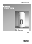
8.2
Displaying Live monitor (current status of
the boiler)
8.3
Display contrast
S.04
Heating mode
burner on
Back
8.3 Displaying Live monitor (current status of the boiler;
example)
Menu ¬ Live Monitor
This function allows you to read the current appliance status of your boiler. In addition, the meaning of the message
is displayed as plain text.
The display is automatically updated if the appliance status
changes.
Status code Meaning
Displays in heating mode
S.00
Heating, no heat demand
S.02
Heating mode, Water pump running
S.03
Heating mode, Ignition sequence
S.04
Heating mode, Burner ignited
S.06
Heating mode, Fan overrun
S.07
Heating mode, Pump overrun
S.08
Heating, remaining cut-off time xx min
Displays in DHW mode (VUW boiler)
S.10
Hot water demand via fan sensor
S.14
DHW mode, Burner on
Displays in cylinder charging mode
S.20
DHW demand
S.22
DHW mode, Pump running
Special cases
S.31
No heat demand, summer operating mode
S.34
Heating mode, frost protection
S.40
Comfort safety mode active
Setting the display contrast
20
Back
8.4 Setting the display contrast
Menu ¬ Information ¬ Display contrast
Using this function, you can set the display contrast in relation to the brightness of the surroundings, to ensure that
the display is clearly legible.
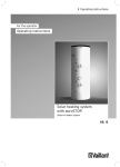
8.4
Setting the language
Language
02 English
Cancel
Ok
8.5 Setting the language
Your approved competent person should have set the boiler
to your desired language. If you wish to set another language, you can proceed as follows:
> Press and hold the right-hand selection button
and the plus button
at the same
time.
> Also press the reset button briefly.
> Continue to press and hold the right-hand selection
and the plus button
until
button
the display offers you the option to set the language.
or plus button
> Use the minus button
to select your desired language.
> Confirm the change by pressing the right-hand selection
("OK").
button
You must confirm the set language twice to ensure that you
have not accidentally set an incorrect language.
8.1 Possible appliance statuses (selection)
Operating instructions ecoTEC plus 0020116701_00
27
8 Additional functions
i
If you have accidentally set a language that you
cannot understand, you can change this as
described above.
or plus button
> Use the minus button
to scroll until your language appears.
8.5
Displaying contact data for the competent
person
Contact data
0219118
Back
8.6 Displaying contact data
Menu ¬ Information ¬ Contact data
If your competent person has entered their telephone
number during the installation, you can read this data
under "Contact data".
8.6
Displaying the serial number and article
number
Menu ¬ Information ¬ Serial number
"Serial number" shows the serial number of the boiler,
which the approved competent person may require from
you.
The article number is found in the second line of the serial
number.
The serial numbers are also located on a plate, which is
stuck behind the front flap on the underside of the boiler in
a plastic fish plate.
8.7
Reset burner off time (resetting burner
anti-cycling time)
Menu structure ¬ Reset burner off time
i
28
This function must only be operated by your
approved competent person.
Operating instructions ecoTEC plus 0020116701_00
Service 9
9
Service
a
9.1
Danger!
Risk of injury and material damage due
to incorrect maintenance and repairs.
If maintenance is not carried out, or carried
out incorrectly, this may adversely affect
the operational reliability of your boiler.
> Never attempt to perform maintenance
work or repairs on your water boiler by
yourself.
> Always employ a recognised heating
engineer.
Servicing the boiler
Permanent operational readiness and safety, reliability and
a long working life require inspections and maintenance
work to be carried out annually on the boiler by your
approved competent person.
Regular servicing ensures maximum efficiency and economical operation of your boiler.
We recommend making a maintenance agreement.
9.2
Caring for your boiler
b
Caution!
Unsuitable cleaning agents can cause
damage!
Unsuitable cleaning agents (scouring or
other cleaning agents) can damage the
exterior, the fittings or the controls.
> Do not use sprays, solvents or cleaning
agents containing chlorine.
> Clean the exterior of your boiler with a damp cloth and a
little solvent-free soap. Do not use any detergent.
Operating instructions ecoTEC plus 0020116701_00
29
10 Decommissioning
10
Decommissioning
> Contact a heating engineer to disconnect the boiler permanently.
10.1
Disposing of the boiler
Do not dispose of your Vaillant ecoTEC plus boiler or any of
its accessories in the household waste.
> Make sure the old unit and any accessories are disposed
of properly.
> Observe national regulations.
10.2
Disposing of the packaging
Arrange for the approved heating engineer who installed
the boiler to dispose of the transport packaging.
30
Operating instructions ecoTEC plus 0020116701_00
Manufacturer's guarantee and works customer services 11
11
11.1
Manufacturer's guarantee and works
customer services
Factory guarantee
Two year guarantee for ecoTEC plus appliances
Vaillant undertakes to rectify any manufacturing defect that
occurs within twenty-four months of the installation date.
For the 2nd year of the guarantee to be valid an annual
service must be carried out by a competent person
approved at the time by the Health and Safety Executive
one year after installation.
The cost of this annual service is not included in the guarantee.
Registering with us
Registration is simple. Just complete the Guarantee Registration Card and return to Vaillant within 30 days of installation. Your details will then be automatically registered
within the Vaillant scheme.
Note: No receipt will be issued.
Immediate help
If your Vaillant boiler develops a fault your first action
should be to contact your installer, as his professional
assessment is needed under the terms of our Guarantee. If
you are unable to contact your installer, phone Vaillant
Service Solutions: 0870 6060 777
11.2
Vaillant Service
To ensure regular servicing, it is strongly recommended
that arrangements are made for a Maintenance Agreement.
Please contact Vaillant Service Solutions
(0870 6060 777) for further details.
Operating instructions ecoTEC plus 0020116701_00
31
12 Glossary
12
Glossary
Air/flue gas duct
The air/flue gas duct consists of all components that route
combustion air to the boiler or exhaust gas from the boiler.
Hot water production in VUW boilers
In the VUW boiler, the water is heated directly in the
through-flow principle.
Comfort mode immediately supplies you with hot water at
the required temperature, without you having to wait for
the water to heat up. In order to do this, the hot water heat
exchanger is kept at a preselected temperature level.
Burner
The burner on a gas-fired condensing boiler is the component on whose surface the gas/air mix is control-burnt.
Calorific value
Unlike the heating value, the calorific value of a fuel
describes the total useable heat during combustion, based
on the quantity of fuel used, including the condensation
heat in the steam. Condensing boilers use this additional
condensation heat to achieve much higher efficiency levels
than conventional boilers.
Controller
The controller is the interface to the boiler and can be used
to adjust the room temperature, hot water temperature,
heating times or night-time temperature reduction.
A distinction is made between room thermostat, weather
compensator and solar controller.
Legionella
Legionella are water-borne bacteria which can quickly propagate and cause serious lung diseases. Legionella bacteria
occur wherever heated water provides the optimum conditions for multiplication. Temporarily heating the water to
above 60 °C kills off the legionella.
Room thermostat
A room thermostat continuously measures the room temperature and compares it with the room temperature you
have set (target room temperature). This allows the heating
system to maintain a constant set temperature in your
room.
In addition, you can enter individual heating times. The target room temperature and the heating times set by you
control the operation of your boiler, the power of which is
adapted automatically to the respective heat demand.
Cylinder charging
Cylinder charging mode refers to the process for heating up
the cylinder.
See also hot water generation.
eBUS
The abbreviation eBUS is short for energyBUS.
The eBUS is a special cable system used in the heating
technology field, which is used for communication between
the heating technology components (e.g. controller, boiler,
vrnetDIALOG).
Weather compensator
A weather compensator is a controller that controls the
heating flow temperature of the heating system as a function of the measured outside temperature.
On the weather compensator you can also enter individual
heating times. The outside temperatures measured and the
heating times set control the operation of the burner, the
output of which is adjusted automatically to the respective
heat demand.
Frost protection
The frost protection function protects your heating system
and dwelling from frost damage. If the heating flow temperature falls below 5 °C when the on/off switch is on, the
boiler comes into operation and heats the heat generation
circuit to approx. 30 °C.
Heating flow temperature
Your boiler heats water which is pumped through your
heating system. The temperature of this hot water as it
leaves the boiler is referred to as the heating flow temperature.
Hot water production in VU boilers
Your boiler heats the water in the domestic hot water cylinder to the selected target temperature. If the temperature
in the domestic hot water cylinder falls by a specific
amount, the water is heated up again to the target temperature.
32
Operating instructions ecoTEC plus 0020116701_00
Index
Index
A
H
Air/flue gas duct ......................................................................... 32
Heating flow temperature ......................................................... 15
Hot water production............................................ 5, 8, 14, 18, 32
Hot water temperature................................................ 6, 8, 15, 17
B
Boiler anti-cycling time ............................................................... 11
C
CE label ............................................................................................ 3
Controller ......................................................... 10, 15, 16, 17, 18, 32
Controls .......................................................................................... 10
Customer service ......................................................................... 31
I
Identification plate ........................................................................ 3
Ignition .................................................................................... 24, 27
Intended use ................................................................................... 5
Isolator devices ............................................................................ 13
L
Legionella protection function ................................................. 17
D
Decommissioning ........................................................................ 30
Display .......................................................................... 10, 14, 15, 19
Disposal ......................................................................................... 30
Domestic hot water
Drawing hot water ................................................................... 8
Setting cylinder charging mode (VUW unit) .................... 16
Setting the hot water temperature .............................. 15, 17
Setting the temperature (VUW unit) ................................. 16
E
Energy saving tips ...................................................................... 20
F
Fault codes ................................................................................... 22
Fault elimination ......................................................................... 24
Filling .............................................................................................. 14
Filling pressure ............................................................................. 14
Filling the heating system ......................................................... 14
Flue gas ........................................................................................... 6
Flue gas smell ................................................................................ 6
Frost
Activating the frost protection function........................... 19
Draining the heating system................................................ 19
Protecting the heating system against frost ................... 19
Operating instructions ecoTEC plus 0020116701_00
M
Malfunction ............................................................................ 23, 24
Must be reported ........................................................................ 27
S
Setting
Setting the hot water temperature (VUW unit) .............. 16
Setting cylinder charging mode (VUW unit) ......................... 16
Status displays ............................................................................ 22
Summer mode ....................................................................... 18, 27
Switching off
Boiler ......................................................................................... 19
Hot water production ............................................................ 18
Switching off the boiler .............................................................. 19
Switching on
Boiler ......................................................................................... 13
Electricity supply ................................................................... 23
Frost protection function...................................................... 19
Setting cylinder charging mode (VUW unit) .................... 16
Switching on the boiler .............................................................. 13
Symbols ............................................................................................ 3
Symbols used .................................................................................. 3
33
Index
T
Temperature
Setting the hot water temperature .............................. 15, 17
Setting the hot water temperature (VUW unit) .............. 16
Troubleshooting .......................................................................... 22
V
Vaillant customer service .......................................................... 31
W
Water shortage............................................................................ 23
34
Operating instructions ecoTEC plus 0020116701_00
Brief operating instructions
For detailed information, please read the corresponding Section in these installation instructions.
1. Switching the heating mode off (summer mode) (¬Section 5.6.2)
Target flow temp.
50
Target flow temp.
50
Heating off
Cancel
Back
> Right-hand selection button " "
> –-Button to "Heating off"
Ok
> Confirm "OK"
2. Setting the heating temperature (switching on Heating mode) (¬ Section 5.2.1)
Target flow temp.
50
Target flow temp.
50
48
Back
> Right-hand selection button " "
Cancel
> +/– button for selecting
the temperature
Ok
> Confirm "OK"
3. Setting the hot water temperature (¬Section 5.3.1)
DHW temperature
50
45
Back
DHW temperature
48
Cancel
> Left-hand selection button > +/– button for selecting
the temperature
" "
Ok
> Confirm "OK"
4. Switching Comfort mode on/off (¬Section 5.3.2)
DHW temperature
50
45
Back
> Left-hand selection button > Right-hand selection button for Comfort mode
" "
Comfort operation
Comfort off
Back
> +/– button for switching
on/off
Comfort operation
Comfort on
Cancel
> Confirm "OK"
Ok
Manufacturer
0020116701_00 GBIE 102011 – Subject to change
Supplier