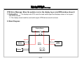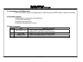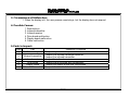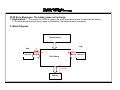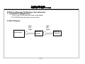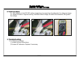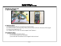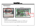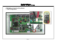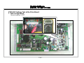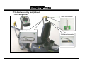
1
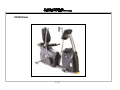
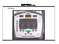
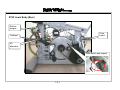
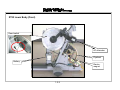
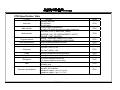
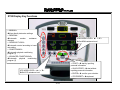
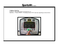
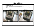
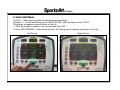
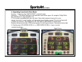
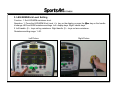
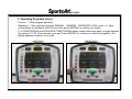
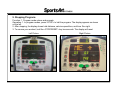
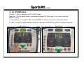
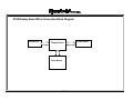
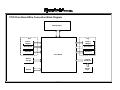
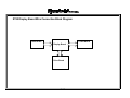
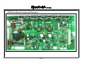
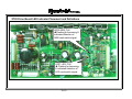
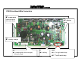
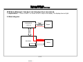
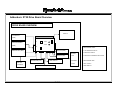
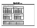
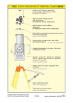
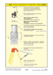
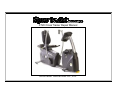
XT20 Cross Trainer Repair Manual
SPORTSART INDUSTRIAL CO., LTD.
.
Contents
1. Component Recognition
1-1-1. XT20 Picture
1-2-1. XT20 Display
1-3-1. XT20 Lower Body (Rear)
1-3-2. XT20 Lower Body (Front)
1-4-1. XT20 Display
1-5-1. XT20 Display Board (Front)
1-5-2. XT20 Display Board (Back)
Note: XT10 and XT20 are mechanically and
electronically identical. The only difference is in
their displays. The residential model XT10 has
user programs. The commercial model XT20
does not have user programs. For general
troubleshooting, this manual applies to XT10
and XT20.
2. XT20 Functions
2-1-1. XT20 Specification Table
2-2-1. XT20 Display Window Functions
2-3-1. XT20 Display Key Functions
Manual updates follow:
Version 1: 12-07-05 – Initial version
Version 2: 02-01-06 – Note below added
3. XT20 Operation
3-1-1. Battery Start Up
3-1-2. Alternator Start Up
3-1-3. Quick Start Mode
3-1-4. Operating from Quick Start Mode
3-1-5. LEG/ARM Work Level Setting
3-1-6. Start Mode
3-1-7. Operate Programs
3-1-8. Operating Programs (Cont.)
3-1-9. Stopping Programs
3-1-10. Battery Shut Off
3-1-12. Show Total Distance
3-1-13. Set KPH/MPH Mode
Note: The cover picture shows a prototype with
handles (like the C5150 bike). Production units
of XT10 and XT20 never had such handles.
For comments or suggestions, please contact
[email protected].
0-0-1
.
Contents
4. Block Diagrams
4-1-1. XT20 Display Board Wire Connection Block Diagram
4-1-2. XT20 Drive Board Wire Connection Block Diagram
5. Connections and Components on Boards
5-1. Display Board
5-1-1. XT20 Display Board Wire Connection Block Diagram
5-1-2. XT20 Display Board Component Placement
5-1-3. XT20 Display Board LED Indicators
5-1-4. XT20 Display Board Wire Connectors
5-2. Drive Board
5-2-1. XT20 Drive Board Wire Connection Block Diagram
5-2-2. XT20 Drive Board Component Placement
5-2-3. XT20 Drive Board LED Indicator Placement and Definitions
5-2-4. XT20 Drive Board Wire Connectors
5-2-5. XT20 Drive Board Fuse Locations
0-0-2
Contents
6. Error Messages
6-1-1. Unit Does Not Start when Keys Are Pressed. (Continued on 6-1-2.)
6-2-1. Move the Pedals or Arms; The Display Does Not Light. (Continued on 6-2-2.)
6-3-1. Move the Pedals or Arms; The Display Leg or Arm RPM Window Shows 0. (Cont. 6-3-2.)
6-4-1. There is No Resistance on Arms or Legs. (Continued on 6-4-2.)
6-5-1. Remote Key Malfunction (Continued on 6-5-2.)
6-6-1. The Battery Does Not Recharge (Continued on 6-6-2.)
6-7-1. Polar Heart Rate Malfunction (Continued on 6-7-2.)
7. Electronic Component Testing
7-1-1. XT20 Alternator Test (Continued on 7-1-2.)
7-2-1. XT20 Battery Voltage Test
7-3-1. XT20 Electro-Magnet Test
7-4-1. XT20 Reed Switch Test (Continued on 7-4-2.)
7-5-1. XT20 Alternator Power Test at the Drive Board (Continued on 7-5-2.)
7-6-1. XT20 Battery Test at the Drive Board (Continued on 7-6-2.)
7-7-1. XT20 Resistance Voltage Test at the Drive Board (Continued through 7-7-3.)
7-8-1. XT20 VCC Voltage Test at the Drive Board (Continued on 7-8-2.)
7-9-1. XT20 VCC Voltage Test at the Display Board (Continued on 7-9-2.)
7-10-1. XT20 Display Board Key Test
7-11-1. XT20 Arm Remote Key Test (Continued on 7-11-2.)
7-12-1. XT20 Polar Heart Rate Test (Continued on 7-12-2.)
7-13-1. Addendum: XT20 Drive Board Overview; Voltage Specifications (7-13-2)
0-0-3
.
XT20 Picture
1-1-1
.
XT20 Display
1-2-1
.
XT20 Lower Body (Rear)
Electromagnet
Drive
board
Flywheel
AC
alternator
Reed switch and magnet
1-3-1
.
XT20 Lower Body (Front)
Reed switch
AC alternator
Flywheel
Battery
Electromagnet
1-3-2
XT20 Display
1-4-1
XT20 Display Board (Front)
1-5-1
XT20 Display Board (Back)
1-5-2
XT20 Specification Table
Function
Heart rate
Main window
Mode window
Program window
Heart rate detection
Key
Work level
Power
Backup Power
Resistance
Seat
Electronic Specifications
Specifics
Telemetry heart rate
65% HR target
80% HR target
Moving prompts or illustrations
Dot matrix 5*5*8 LED two-color dot matrix (red/green)
Work Lever(LEG)/ Work Lever(ARM)
CALORIES / CAL / HR / DISTANCEMETS / WATTS
LEG RPM / TIME / ARM RPM
MANUAL / RANDOM / CARDIO / WT LOSS /
CONDITONING / ADVANCED CONDITONING
POLAR wireless telemetry heart rate
Key/ toggle switch
Work level(LEG)1~20
Work level(ARM)1~20
Hand/leg independent power generation
Rechargeable battery (hand/leg independent batteries)
Leg: electro-magnetic (belt drive)
Arm: electro-magnetic (chain drive)
Adjustable back
Adjustable seat
Rechargeable battery: 6.4 V
Alternator: AC brushless
Resistance voltage – arm: 2.0~10.2V
Resistance voltage – leg: 2.7~17.2V
2-1-1
Model
XT20
XT20
XT20
XT20
XT20
XT20
XT20
XT20
XT20
XT20
XT20
XT20
XT20 Display Window Functions
Heart rate
ÎShows 65% HR target
ÎShows actual heart rate
ÎShows 80% HR target
Main window
ÎShows prompts and
illustrations
Leg work level
ÎShows leg resistance
level value
Arm work level
ÎShows arm resistance
level
Calorie
ÎShows calorie burn
and calorie burn per hour
Leg RPM
Î Shows rotations per
minute (leg)
METS
ÎShows METS and
WATTS values
Time
ÎShows time
Distance
ÎShows
distance
2-2-1
Arm RPM
ÎShows rotations per
minute (arm)
XT20 Display Key Functions
<MANUAL>
ÎKeys directly determine settings
<RANDOM>
ÎAutomatic
random
resistance
changes
<CARDIO/WT LOSS>
ÎAutomatic control according to heart
rate setting
<CONDITIONING>
ÎAutomatic physical conditioning
program (1)
<ADVANCED CONDITIONING>
ÎAutomatic
physical
conditioning
program (2)
ARM WORK LEVEL<▲>/<▼>
ÎSet ARM resistance level
<START>Î start by inputting
personal information
<QUICK START>Î start without
inputting personal information
<ENTER>Î confirm your selection
LEG WORK LEVEL<▲>/<▼>
ÎSet LEG resistance level
<STOP/RESET>Îstop/reset
2-3-1
1. Battery Start Up
Function: 1. Use battery power to activate the unit.
Operation: 1. Press <START>. The display shows “XT20” and starts operating as shown below.
3-1-1
2. Alternator Start Up
Function: 1. Use power from the alternator to activate the unit.
Operation: 1. Move the pedals or handles. The display shows “XT20” and starts operating as shown
below.
Left Picture
Right Picture
3-1-2
3. Quick Start Mode
Function: 1. Start exercising without inputting personal settings.
Operation: 1. To start exercising, press <QUICK START> after the display shows “XT20”.
The display will appear as shown below on the left.
2. Move the pedals or handles. Time accumulates from 0:00.
3. Press <STOP/RESET>. Exercise mode stops. The startup screen appears as shown on the right.
Left Picture
Right Picture
3-1-3
4. Operating from Quick Start Mode
Function: 1. Exercise from QUICK START in manual mode
Operation: 1. The default settings in this exercise mode follow: age is 35; weight is 75Kg/165Lb;
arm resistance is 3; leg resistance is 5.
2. The course is represented by an oval track. Green dots represent area yet to cover;
orange represents current location; red represents area already covered. See picture below left.
3. While you exercise, CALORIES/CAL HR, DISTANCE, METS/WATTS values show.
Distance values accumulate. RPM values appear for both legs and arms. See picture below right.
4. Directly press LEG WORK LEVEL▼/▲ or ARM WORK LEVEL▼/▲ keys to control
resistance settings.
Left Picture
Right Picture
3-1-4
5. LEG/ARM Work Level Setting
Function: 1. Set LEG/ARM resistance level.
Operation: 1. Press the LEG/ARM Work Level ▼/▲ key on the display or press the ┼/— key on the handle
to change LEG and ARM resistance settings. Left: display keys. Right: handle keys.
2. Left handle ┼/— keys set leg resistance. Right handle ┼/— keys set arm resistance.
Resistance setting range: 1~20.
Left Picture
Right Picture
3-1-5
6. Start Mode
Function: 1. Exercise using user personal information for more accurate physical feedback readings.
Operation: 1. Press <START> after the display shows “XT20” to input user information. The display appears
as shown on the left.
2. To enter age and weight, press ▲\▼ keys or numbers on the bottom of the display.
Press <ENTER> to confirm your choice as shown below on the right.
3. After pressing <ENTER>, the display, automatically calculates calorie burn, etc., according
to your information.
Left Picture
Right Picture
3-1-6
7. Operate Programs
Function: 1. Operate automatic programs.
Operation: 1. After entering age and weight information, all program LEDs light as shown on the left.
2. Press any key (MANUAL、RANDOM、CARDIO/WT LOSS、CONDITIONING、ADVANCED
CONDITIONING) as shown on the right to activate the related program.
3. Programs explanations follow: (1) MANUAL-directly set resistance; (2) RANDOM-resistance
changes at random; (3) CARDIO-aerobic conditioning; WT LOSS-weight loss
mode; (4) CONDITIONING-physical conditioning; (5) ADVANCED CONDITIONING –
advanced physical conditioning.
Left Picture
Right Picture
3-1-7
8. Operating Programs (Cont.)
Function: 1. Other program operation.
Operation: 1. After entering a program (MANUAL、RANDOM、CARDIO/WT LOSS), press ▲\▼ keys
on the display or handles to enter the time, then press <ENTER> to confirm your choice.
2. In CONDITIONING and ADVANCED CONDITIONING modes, press these keys again to toggle between
four options, P1~P4. Exercise time is pre-set. Press <ENTER> to confirm your choice of programs. The
display appears as shown on the right.
Left Picture
Right Picture
3-1-8
9. Stopping Programs
Function: 1. Program mode values and prompts.
Operation: 1. In program modes, press <STOP> to halt the program. The display appears as shown
on the left.
2. After stopping, the display shows total distance, calorie expenditure, and time. See right.
3. To resume your workout, hold the <STOP/RESET> key two seconds. The display will reset.
Left Picture
Right Picture
3-1-9
10. Battery Shut Off
Function: 1. Automatically turn off the unit after exercising.
Operation: 1. Simultaneously press <ENTER>+LEG Work Level <▼> to turn off the display.
The battery circuit is disengaged, and the display shuts off as shown on the right.
Picture Left
Picture Right
3-1-10
11. Power Save Mode
Function: 1. Start the power saving mode.
Operation: 1. When there is no movement signal detected for over 30 seconds, the display automatically
shuts off and a “bouncing ball” pattern appears.
2. Press <START> or move the pedals or handles to resume exercising. The display shows the
previous screen as shown on the right.
Left Picture
Right Picture
3-1-11
12. Show Total Distance
Function: 1. See total distance.
Operation: 1. Simultaneously press <STOP/REST>+<ENTER>+<DISPLAY Lock> keys.
The display appears as shown.
K: KPH
M: MPH
Program nationality
Total distance
3-1-12
13. Set KPH/MPH Mode
Function: 1. Set unit operation in KPH or MPH mode.
Operation: 1. At the startup screen, simultaneously press LEG Work Level <▼/▲> keys to enter the
MODIFY setting.
2. Then press<▼/▲> to toggle to YES. Press <ENTER> to confirm your choice. See picture on left.
3. Press ▼/▲ keys to toggle between KG and LB. Then press <ENTER> to confirm your choice. See right.
Left Picture
Right Picture
3-1-13
XT20 Display Board Wire Connection Block Diagram
Polar Board
Display Board
Drive Board
4-1-1
C-Safe Board
XT20 Drive Board Wire Connection Block Diagram
控制板
Display
Board
Arm
手部
Leg
腳部
電磁鐵
Magnet
Electro-
Electro電磁鐵
Magnet
Reed Switch
磁簧感應線
Reed Switch
磁簧感應線
Alternator
發電機
Alternator
發電機
Drive
Board
驅動板
Battery
充電器
Charger
紅外線按
Infrared
Key
Board
鍵小板
Battery
蓄電池
搖臂按鍵
Keys
Handle
4-1-2
XT20 Display Board Wire Connection Block Diagram
Polar Board
Display Board
Drive Board
5-1-1
C-Safe Board
XT20 Display Board Component Placement
5-1-2
XT20 Display Board LED Indicators
POWER1 LED
ÎLit=5V power supply
LED1 C-SAFE Indicator
ÎLit=C-SAFE operation
5-1-3
XT20 Display Board Wire Connectors
CON1
ÎTo drive board
CON4
ÎTo C-SAFE board
CON2
Î To POLAR
receiver board
5-1-4
XT20 Drive Board Wire Connection Block Diagram
控制板
Display
Board
Arm
手部
Leg
腳部
電磁鐵
Magnet
Electro-
Electro電磁鐵
Magnet
Reed Switch
磁簧感應線
Reed Switch
磁簧感應線
Alternator
發電機
Alternator
發電機
Drive
Board
驅動板
Battery
充電器
Charger
紅外線按
Infrared
Key
Board
鍵小板
Battery
蓄電池
搖臂按鍵
Keys
Handle
5-2-1
XT20 Drive Board Component Placement
5-2-2
XT20 Drive Board LED Indicator Placement and Definitions
LED2 ARM_CLK
ÎFlashing or becoming lit
indicates detection of
ARM reed switch signal.
LED1 LEG_CLK
Î Flashing or becoming
lit indicates detection of
LEG reed switch signal.
5-2-3
XT20 Drive Board Wire Connectors
J4
ÎTo reed switch,
electro-magnet,
alternator (arm)
J2
ÎTo display
board
J8
ÎTo battery charger
J5
ÎTo reed switch, electro-magnet,
alternator (leg)
J1
J3/J7
ÎTo battery
ÎJ3, To right handle keys
ÎJ7, To left handle keys
5-2-4
XT20 Drive Board Fuse Locations
F1 3A
Alternator fuse
F2 2A
Battery fuse
F3 2A
Battery charger fuse
5-2-5
.
XT20 Error Messages: Unit does not start when keys are pressed.
1. Explanation: 1. Press <START> or <Quick START> keys on the display. The display does not light.
2. Block diagram:
Display Board
按STAR
StartT
o Power LED
Quick
或Q
UI CK Start
START
Keypad
Keypad
CABLE
控制板
Drive
Board
驅動板
Voltage
開機電壓
Battery
蓄電池
Fuse F2
保險絲F2
6-1-1
POWER ◎
3. Circumstance of Malfunction:
1. Display does not light up.
4. Possible Causes:
1. Battery is bad.
2. Drive board is bad.
3. Display board is bad.
4. Data cable is bad.
5. Parts to Inspect:
Order
Part
1
Battery
2
Drive board
3
Display board
4
Data cable
Inspection Procedure
1. Test whether battery voltage exceeds 5.5V. If not, recharge battery.
If not possible, replace the battery.
1. Test battery fuse F2 on the drive board F2 for continuity. Replace if
necessary.
2. Inspect drive board wire connections. Reconnect if necessary.
1. Inspect the data cable connection to the display.
2. Inspect whether the power LED on the display lights up.
1. Inspect the cable for breaks or shorts.
2. Inspect cable connections from the display to the drive board.
6-1-2
.
XT20 Error Message: Move the pedals or arms. The display does not light.
1. Explanation: 1. When pedals or arms move, the alternator power goes to the drive board; the display detects
the reed switch signal, and the display lights up.
2. Without either the alternator voltage or the reed switch signal, the display cannot light.
2. Block Diagram:
Display
控制板
Board
POWER
Arm
手
部
Reed
Switch
Leg
腳
部
磁簧感應線
Display
驅 動 Board
板
CL K
Reed
Switch
磁簧感應線
CL K
Alternator
發電機
Alternator
發電機
V
L ED1
L ED2
CLK
Indicators
CL K
指示燈
6-2-1
V
3. Circumstance of Malfunction:
1. Move the pedals or arms; the display does not light up.
4. Possible Causes:
1. Reed switch malfunction
2. Drive board malfunction
3. Display board malfunction
4. Break in the data cable
5. Alternator malfunction
5. Parts to Inspect:
Order
Part
1
Reed switch
2
3
4
5
Drive board
Display board
Data cable
Alternator
Inspection Procedure
1. Inspect the reed switch wire connection.
2. Inspect the LED1 and LED2 indicators on the drive board.
1. Inspect the LED1 and LED2 indicators on the drive board.
1. Inspect the display board for a malfunction.
1. Inspect all cables and their connections.
1. Inspect the alternator.
6-2-2
.
XT20 Error Message: Move the pedals or arms; the display leg or arm RPM window shows 0.
1. Explanation: 1. The display board CPU reads the reed switch signal and displays values in the leg and
arm RPM windows.
2. If the display cannot read the reed switch signal, RPM values cannot be shown.
2. Block Diagram:
Display
控 制Board
板
腳Leg
部 CLK
CL K
Arm
手
部 CLK
CL K
Reed
Switch
磁簧感應線
驅Drive
動板
Board
蓄電池
Battery
LED1 LED2
Indicators
6-3-1
Reed
Switch
磁簧感應線
3. Circumstance of Malfunction:
1. Move the pedals or arms; the display does not show leg and arm RPM speed in respective windows.
4. Possible Causes:
1. Reed switch or reed switch wire malfunction
2. Drive board malfunction
3. Display board malfunction
4. Wires are disconnected or broken.
5. Parts to Inspect:
Order
Part
1
Reed switch wire
2
3
4
Drive board
Display board
Cables
Inspection Procedure
1. Inspect the reed switch wire connection.
2. Inspect LED1 and LED2 on the drive board.
1. Inspect LED1 and LED2 on the drive board.
1. Inspect the display board for a malfunction.
1. Inspect all cables and their connections.
6-3-2
.
XT20 Error Message: There is no resistance on arms or legs.
1. Explanation: 1. The reed switch CLK signal does not reach the display CPU. The unit does not start.
There is no resistance.
2. The display has not sent the resistance signal to the drive board. The drive board has not sent voltage
to the electro-magnet, so there is no resistance.
2. Block Diagram:
Display
控制板
Board
CABLE
阻
CLK
CLK
Alternator
發電機
號
V
Reed
磁簧感應線
Switch
AC
Voltag
AC
電壓
e
Resistance
力
Signal
訊
Drive
驅動板
Board
6-4-1
Electro電磁鐵
Magnet
Resistance
阻力電壓
Voltage
3. Circumstance of Malfunction:
1. There is no resistance on legs or arms.
4. Possible Causes:
1. Reed switch or wire malfunction
2. Drive board malfunction
3. Display board malfunction
4. Cable malfunction
5. Electro-magnet malfunction
6. Alternator malfunction
5. Parts to Inspect:
Order
1
2
3
4
5
6
Part
Reed switch and wire
Drive board
Display board
Cable
Electro-magnet
Alternator
Inspection Procedure
1. Inspect the reed switch and wire.
1. Inspect whether the drive board is sending voltage to the magnet.
1. Inspect whether the display board is malfunctioning.
1. Inspect cables and their connections.
1. Inspect the electro-magnet.
1. Inspect the alternator.
6-4-2
.
XT20 Error Message: Remote Key Malfunction
1. Explanation: 1. When the unit is on, the user presses remote keys, but there is no response from the display.
2. Block Diagram:
Display
控制板
Board
左
手
Left
左
手
Right
Remote
搖臂按鍵
Keys
Remote
搖臂按鍵
Keys
Infrared
紅
外 線Transmitter
發射器
驅動
板
Drive
Board
Infrared
紅
外 線Transmitter
發射器
按鍵訊號
紅Infrared
外 線 Receiver
接受器
Key Signal
6-5-1
紅Infrared
外 線Receiver
接受器
3. Circumstance of Malfunction:
1. When the display is lit, the user presses remote keys, but the display does not respond.
4. Possible Causes:
1. Remote keys
2. Infrared transmitter
3. Infrared receiver
4. Drive board malfunction
5. Display board malfunction
6. Cable malfunction
5. Parts to Inspect:
Order
1
Part
Remote keys
2
Infrared transmitter
3
4
5
6
Infrared receiver
Drive board
Display board
Cables
Inspection Procedure
1. Inspect keys and the key circuit board.
1. Inspect the infrared transmitter batteries.
2. Inspect the infrared transmitter.
1. Inspect the infrared receiver.
1. Inspect the drive board wire connections.
1. Inspect the display board wire connections.
1. Inspect all cables and their connections.
6-5-2
.
XT20 Error Messages: The battery does not recharge.
1. Explanation: 1. At a speed of 40 RPM or higher, the drive board emits power to replenish the battery.
2. The drive board does not send voltage to the battery; the battery does not recharge.
2. Block Diagram:
Display
Board
控制板
Arm
手部
Alternator
發電機
Leg
腳部
AC
Voltage
AC電壓
AC
AC電壓
Voltage
Alternator
發電機
Drive
Board
驅動板
DC
Voltage
DC電壓
Battery
蓄電池
6-6-1
3. Circumstance of Malfunction:
1. The alternator does not provide AC power to the rectifier board.
2. The drive board does not provide DC voltage to recharge the battery.
4. Possible Causes:
1. Alternator malfunction
2. Drive board malfunction
3. Battery malfunction
4. RPM value does not meet or exceed 40 RPM, so there is no opportunity to recharge the battery.
5. Parts to Inspect:
Order
1
Part
Alternator
2
Drive board
3
Battery
Inspection Procedure
1. Inspect the alternator for AC voltage to the drive board.
1. Inspect the F1 and F2 fuses on the drive board.
2. Inspect whether the drive board provides DC voltage to the battery.
1. Inspect the battery wire connections.
2. Inspect whether battery voltage is lower than 3V. If so, the battery
is defective; replace it.
6-6-2
.
XT20 Error Message: POLAR heart rate malfunction
1. Circumstance of Malfunction:
1. There is no POLAR heart rate value on the display.
2. The POLAR heart rate value is not accurate.
2. Block Diagram:
Heart
Rate
Signal
Heart
Rate
Signal
Display Board
Heart Rate
Receiver
6-7-1
Heart Rate
Transmitter
.
3. Possible Causes:
1.
2.
3.
4.
5.
POLAR heart rate transmitter malfunction
POLAR heart rate receiver malfunction; receiver does not detect transmitter signal.
POLAR heart rate receiver interference
POLAR heart rate 3-PIN cable is not connected.
Display malfunction: CPU does not detect the POLAR heart rate signal.
4. Parts to Inspect:
Order
1
2
3
4
Part
POLAR
heart rate transmitter
POLAR
heart rate receiver
Inspection Procedure
1. Inspect the transmitter and brand.
2. Replace the transmitter.
1. Inspect the POLAR receiver board position. Some positions detect
better than others.
2. Inspect the POLAR heart rate receiver board for component
connections.
3-pin cable connection 1. Inspect POLAR heart rate board wire connections.
Display board
1. Inspect the 3-pin cable connections.
2. Press on the display board IC chip to reinsert pin connections.
6-7-2
.
XT20 Alternator Test
1. Alternator test configuration:
7-1-1
.
2. Test Procedure:
2-1. Put voltmeter to the 200 VAC setting. Inspect any two wires from the alternator for voltage as shown.
2-2. When the arms or legs are moving, voltmeter shows voltage; the faster the movement, the greater
the voltage.
3. Troubleshooting:
3-1. If there is no voltage,
(1) Inspect all wire connections;
(2) Inspect AC alternator. Replace if necessary.
7-1-2
.
XT20 Battery Voltage Test
1. Test Configuration:
2. Test Procedure:
2-1. Put voltmeter to the 20 VDC setting.
2-3. Place probes as shown, with the red on the red terminal, the black on the black terminal.
2-4. Normal voltage: 5.6 ~6.5 VDC. If lower than 5.5 VDC, please move the pedals or arms swiftly
to recharge the battery.
3. Troubleshooting:
3-1. If there is no voltage, or voltage is too low:
(1) Inspect the battery wire connections.
(2) Inspect whether fuse F2 has broken.
3-2. Recharge the battery by moving at 40 RPM or more.
7-2-1
.
XT20 Electro-Magnet Test
1. Test Configuration:
2. Test Procedure:
2-1. Disconnect the CN2 wire connection from the drive board.
2-2. Put the voltmeter to the ohm setting. Place probes as shown on the two, blue wires of the magnet.
2-3. Normal ohm specification: 20.
2-4. If greater than 20 or open, the electro-magnet it bad. Replace it.
3. Troubleshooting:
3-1. If the reading is not normal, inspect:
(1) The electro-magnet wire connections.
(2) The cable and connections from the magnet to the drive board.
7-3-1
.
XT20 Reed Switch Test
1. Test Configuration:
Left Picture
Right Picture
LED1、LED2
CLK
2. Test Procedure
A. Arm RPM
1. Press the<START>key. The display lights up.
2. Move the arms. The drive board CLK LED flashes. Display shows<ARM RPM>value.
3. Move the arms once per second. The display<ARM RPM>window shows 60 RPM.
7-4-1
.
XT20 Reed Switch Test
2. Test Procedure:
B. Leg RPM
1. Press the<START>key. The display lights up.
2. Move the pedals. Drive board CLK LED flashes. Display shows the<LEG RPM>value.
3. Move the arms once per second. The display <LEG RPM>window shows 60 RPM.
3. Troubleshooting:
1. If your test results differ, the reed switch is unstable or bad.
7-4-2
.
XT20 Alternator Power Test at the Drive Board
1. Test Configuration:
7-5-1
.
2. Test Procedure:
2-1. Put voltmeter to the 200 VDC setting. Place probes on the drive board TP1-TP2 connectors as shown.
2-2. Move either pedals or arms. Normal voltage: 10-150 VDC or more.
2-3. If not as above, the alternator is bad.
3. Troubleshooting:
3-1. If there is no voltage, inspect:
(1) All cable connections.
(2) F1 fuse on the drive board. Replace if necessary.
(3) Inspect alternator for damage.
7-5-2
.
XT20 Battery Test at the Drive Board
1. Test Configuration:
7-6-1
.
2. Test Procedure:
2-1. Put voltmeter to the 20 VDC setting. Place probes separately on J1 red and black terminals.
Normal reading: 6 volts.
2-2. If less than 5.5 VDC, recharge the battery. 5.3 VDC is the lowest voltage at which the display
can operate.
2-3. To recharge the battery, exercise at 40 RPM or more for 20 minutes or more.
2-4. If the battery has less than 3 VDC, replace it.
3. Troubleshooting:
3-1. If battery voltage is less than 5.5 VDC, recharge the battery as follows:
A. Exercise: Exercise at more than 40 RPM for 20 minutes or more, to recharge the battery.
B. Battery charger: Connect the XT-20 battery charger.
7-6-2
XT20 Resistance Voltage Test at the Drive Board
1. Test Configuration - ARM Resistance Voltage Test
7-7-1
Test Configuration - LEG Resistance Voltage Test
7-7-2
2. Test Procedure
ARM Resistance Voltage Test
(1) Put voltmeter to the 20 VDC setting. Place probes on J5 blue-blue wire connectors. Move arms.
(2) Press ARM LEVEL<▲> key until the display shows resistance level 20. Arm resistance is highest.
Normal voltage reading: 10 VDC approximately.
(3) Press ARM LEVEL<▼> key until the display shows resistance level 1. Arm resistance is lowest.
Normal voltage reading: 2.0 VDC approximately.
LEG Resistance Voltage Test
(1) Put voltmeter to the 20 VDC setting. Place probes on J6 blue-blue wire connectors. Move arms.
(2) Press LEG LEVEL<▲> key until the display shows resistance level 20. Leg resistance is highest.
Normal voltage reading: 17.2 VDC approximately.
(3) Press LEG LEVEL<▼> key until the display shows resistance level 1. Leg resistance is lowest.
Normal voltage reading: 2.7 VDC approximately.
3. Troubleshooting:
(1) If there is no voltage, the drive board is not emitting voltage for resistance. Inspect:
A. Cable connections
B. Alternator
C. Alternator fuse on the drive board
D. Drive board
E. Display board
7-7-3
.
XT20 VCC Voltage Test at the Drive Board
1. Test Configuration:
Normal reading: 5 VDC.
7-8-1
.
2. Test Procedure:
2-1. Put voltmeter to the 20 VDC setting. Place probes on the drive board J2 pin1-pin18 terminals as shown.
This is the VCC circuit.
2-2. Exercise on the unit or press the <START> or <QUICK START> key on the display. The display should
beep once and light.
2-3. Normal reading: 4.8-5.2 VDC approximately.
3. Troubleshooting:
3-1. If the display does not light.
(1) Inspect cable connections.
(2) Inspect fuses on the drive board. Replace if necessary.
7-8-2
XT20 VCC Voltage Test at the Display Board
1. Test Configuration:
Capacitor C10
7-9-1
2. Test Procedure:
2-1. Put voltmeter to the 20 VDC setting. Place probes on C10 pins as shown.
2-2. Exercise on the unit or press the <START> key. The display should beep once; the POWER1 LED
should light; and all windows should light.
2-3. Normal reading: 4.8-5.2 VDC.
3. Troubleshooting:
3-1. If the display does not light, inspect:
(1) Drive board to display cables and their connections
(2) Display board for VCC voltage
7-9-2
XT20 Display Board Key Test
1. Test Procedure
1-1. Test for continuity
(1) Put voltmeter to the ohm setting. Place probes on the two terminals on the right or left side as shown.
(2) Press on the key. Voltmeter should show 0Ω.
(3) If the display shows no reaction, the key is broken.
1-2. Test for open
(1) Put voltmeter to the ohm setting. Place probes on the two terminals on the right or left side as shown.
(2) Without pressing on a key, there should be no reaction on the voltmeter.
(3) If the voltmeter reads 0 ohm when the key is not pressed, the key has a short. Replace it.
Left Picture
Right Picture
7-10-1
.
XT20 Arm Remote Key Test (Infrared)
1. Test Configuration:
1. Key circuit board
3. Infrared receiver
2. Infrared transmitter
7-11-1
.
2. Test Procedure:
1. Left remote test (leg)
(1) Set display to MAN’L mode.
(2) Use the left remote to set the leg resistance. Resistance values in the display LEG WORK
window change accordingly.
(3) LEVEL range: 1-20.
2. Right remote test (arm)
(1) Set display to MAN’L mode.
(2) Use the right remote to set the arm resistance. Resistance values in the display ARM WORK
window change accordingly.
(3) LEVEL range: 1-20.
3. Troubleshooting:
3-1. If there is no reaction to the keys, inspect:
(1) Whether keys are stuck; inspect the key circuit board;
(2) Infrared transmitter battery voltage;
(3) Wires and their connections.
7-11-2
.
XT20 Polar Heart Rate Test
1. Test Configuration:
Target heart rate
windows
Actual heart rate
display
Polar transmitter
7-12-1
.
2. Test Procedure:
1. Static test
(1) Put on the POLAR heart rate transmitter.
(2) Sit with the transmitter within 80 cm of the display.
(3) Press QUICK START.
(4) Within five seconds, the display should show the heart rate reading. If there is no heart rate
reading, the transmitter or receiver is malfunctioning.
2. Active test
(1) Put on the POLAR heart rate transmitter.
(2) Sit with the transmitter within 80 cm of the display. Exercise on the unit.
(3) The display should show the heart rate reading.
3. Troubleshooting:
3-1. If there is no reading during the static test, inspect:
(1) POLAR receiver wire and its connections
(2) Replace the POLAR receiver wire as a test
(3) Replace the POLAR transmitter batteries as a test
3-2. If there is no reading during the active test, inspect:
(1) The POLAR receiver is connected properly
(2) The POLAR transmitter battery voltage. Replace the transmitter as a test.
7-12-2
.
Addendum: XT20 Drive Board Overview
DRIVE BOARD OVERVIEW
DISPLAY
ALTERNATOR
(ARM)
DRIVE BOARD
F1
F2
LED1
ELECTRO-MAGNET
LED2
(ARM)
F3
DRIVE BOARD FUSES:
F1 ALTERNATOR FUSE 3A
REMOTE (ARM)
REED SWITCH (ARM)
REMOTE (LEG)
ALTERNATOR (LEG)
REED SWITCH
BATTERY:
F2 BATTERY FUSE 2A
6 VDC
F3 BATTERY CHARGER FUSE 2A FUSE
CHARGING:
DRIVE BOARD LEDS:
7.2 VDC
LED1 LEG CLK
BATTERY
CHARGER
LED2 ARM CLK
ELECTRO-MAGNET (LEG)
7-13-1
.
Addendum: Voltage Specifications
RESISTANCE LEGS
(BLUE/BLUE)
LEVEL RPM VOLTAGE
DC
1
30
2.75 VDC
5
30
5.85 VDC
10
60
13.5 VDC
15
60
15.5 VDC
ALTERNATOR LEGS
(BLACK/WHITE)
RPM VOLTAGE AC
40
13 VAC
60
20 VAC
90
33 VAC
RESISTANCE ARMS
(BLUE/BLUE)
LEVEL RPM VOLTAGE
DC
1
50
1.3 VDC
5
50
4.5 VDC
10
50
5.2 VDC
15
50
6.9 VDC
ALTERNATOR ARMS
(BLACK/WHITE)
RPM VOLTAGE AC
40
22 VAC
60
32 VAC
80
45 VAC
REED SWITCHES: CONTINUITY WITH MAGNET PRESENT; NO CONTINUITY WITH NO MAGNET PRESENT.
REMOTES (REMOTES EACH HAVE TWO AAA BATTERIES)
CONSTANT
CONSTANT (OUTPUT)
BLUE/BROWN
(INPUT) BLUE/BLACK
5.2 VDC
4.53 VDC
PRESS/HOLD BLUE/BROWN
4.59/4.60 VDC
7-13-2