1
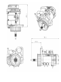
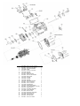
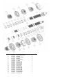
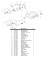
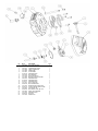
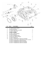
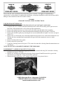
Please read this entire installation/instruction sheet prior to assembly. We highly recommend using a
experienced v-twin mechanic to complete this installation, as improper installation could result in injury and/or
damage to the transmission that will void the warranty.
1216-0001
GEAR SET INSTALLATION INSTRUCTIONS
5 SPEED GEAR SET REMOVAL
NOTE: Leave the transmission case in the frame unless the case itself requires replacement.
1. Using the OE service manual, drain the transmission and remove all necessary parts to gain access to
both ends of the transmission as well as the top of the transmission.
2. Remove the transmission top cover, then remove the shifter cam and shifter fork assemblies.
3. Remove the bearing inner race from the transmission mainshaft using Jims tool part # 34902-84.
4. Remove the final drive pulley by removing the two screws and then the lock plate. Use Jim’s tool part #
94660-37A.
5. Remove the six socket head screws from the transmission trap door to free it from the transmission case.
Pull the side door, mainshaft and countershaft with gears from the transmission case as a single
assembly.
6. Remove and discard the door gasket.
1. Remove main drive gear using
2. Using Jim’s bearing remover tool part # 1720, remove the main drive bearing from the transmission case
and discard.
NOTE: DO NOT USE A HAMMER TO REMOVE THE SIDE DOOR
POWERDRIVE™ 6 SPEED GEAR SET INSTALLATION
1. Install a new main drive gear bearing per your OE service manual and using Jim’s main drive bearing
installation tool part # 35316-80.
2. Install a new retaining ring with the beveled edge facing outward. Install the main drive gear in the
transmission case using Jim’s 35316-80 main drive gear tool.
3. Shorten the shifter shaft sleeve .035” using a reamer & pilot. (See pictures below)
12450 Whittier Blvd., Whittier, CA 90602
562-907-2600 Voice 562-907-2606 fax
www.riveraprimoinc.com
4. Verify that the two locating dowels are in place on the right side of the transmission case and place a
new supplied gasket on the dowels. Inserting the mainshaft through the main drive gear, slide the entire
RPI PowerDrive™ gear assembly in until the trap door rests against the case. Tighten the four 5/16 inch
mounting screws to 13-16 ft-Ibs. Tighten the two 1/4 inch screws to 84-108 ln-Ibs.
5. With the spring side facing the transmission case, install the main drive gear seal using Jim’s main drive
gear seal installer part # 2256.
6. Check for sharp edges or burrs and remove if necessary, then install spacer sleeve on the main drive gear
with chamfer facing inboard.
7. Install the transmission sprocket.
8. Install the belt on the sprocket as the sprocket is installed on the main drive gear. Install the sprocket nut
tightening to 60 ft-lbs & then the sprocket nut lock plate. Align the two holes in the lock plate with the
threaded holes in the pulley. Use one drop of red thread locker on each bolt and then torque to 90-110 in.
lbs.
NOTE: The transmission sprocket nut has left handed threads. You must turn the nut counterclockwise to
install on the main drive gear. Do not loosen sprocket nut when attempting to align holes on the lock plate and
pulley.
9. Install the shifter cam and fork assemblies.
10. Install the top cover with vent tube & neutral safety switch using the new gasket supplied.
11. Install the bearing inner race on the transmission main shaft if using a primary chain drive, or omit this
step if using primary belt drive.
12. Install the pushrod end with the throw-out bearing in the right side of the mainshaft.
13. Install the clutch release assembly into the end cover per OE service manual.
14. Install end cover with new gasket supplied.
CASE MODIFICATIONS
It may be necessary on some models to make a minor modification to the stock case prior to final installation of
the PowerDrive™ gear set. Is some case there is a fitment issue in the upper right inside corner that requires
removal of some material. (See photo below). It may also be necessary to enlarge the dowel pin holes on some
OE cases to except the dowel pins in our trap door.
12450 Whittier Blvd., Whittier, CA 90602
562-907-2600 Voice 562-907-2606 fax
www.riveraprimoinc.com
6a
No
1
2
3
4
5
6
6a
7
8
9
10
11
12
13
14
15
16
17
18
19
20
21
22
23
24
25
26
27
RPI #
1100-0080
1100-0081
1094-0018
1217-0600
1100-0017
1216-0302
1217-0613
1100-0031
1100-0020
1219-0604
1216-0301
1216-0303
1216-0300
1094-0006
1100-0027
1100-0028
1217-0649
1094-0016
1100-0082
2223-0015
1148-0013
1217-0603
1179-0050
1217-0616
3217-0030
3223-0002
1100-0030
1100-0081
PART NAME
QTY
1/4-20*1 1/4" 31.7L HSCS
4
1/4-20*2 1/4" 31L HSCS
4
TOP COVER GASKET
1
LEVER
1
5/16-24*1-25.4L SHCS
1
2M FORK
1
FORK PIN
4
INSERT HEX NUT
2
1/2-20*1/2 SET SCREW
1
FORK SHAFT
1
3C FORK
1
4C FORK
1
1M FORK
1
TRAPDOOR GASKET
1
1/4-20*2 1/4 SHCS
3
1/4-20*1 1/4 SHCS
4
LOCATING PIN
2
GASKET END COVER
1
1/4 " SOCKET BOLT (L=55 2EA) 6
SPROCKET 32T
1
QUAD SEAL-PACKING
1
PULLEY SPACER
1
MAIN OIL SEAL
1
MAINSHAFT PUSH ROD
1
NUT LOCK PLATE
1
SPROCKET NUT
1
1/4*20 5/8 HSCS
2
1/4-20*2 1/4" HSCS
1
1
1
1
No
1
2
3
4
5
6
7
8
9
10
11
12
13
14
15
16
17
18
19
RPI PART #
1219-0602
1018-0007
1217-0703
1101-0053
1217-0611
1018-0008
1179-0052
1216-0055
1216-0057
1216-0056
1216-0206
1219-0600
1216-0058
1216-0054
1216-0051
1216-0060
1216-0206
1216-0052
1216-0059
PART NAME
COUNTER SHAFT
SPLIT CASE BEARING
WASHER
RETARNING RING
WASHER
ROOL BEARING
OIL SEAL
GEAR 1ST C/S
GEAR 4TH C/S
GEAR 3RD C/S
GEAR 2ND C/S
MAIN SHAFT
GEAR 5TH C/S
GEAR 6TH M/N
GEAR 1ST M/N
GEAR 4TH M/N
GEAR 3RD M/N
GEAR 2ND M/N
GEAR 5TH M/N
QTY
1
5
6
5
1
2
1
1
1
1
1
1
1
1
1
1
1
1
1
No
1
2
3
4
5
6
7
8
9
10
11
12
13
14
15
16
17
18
19
20
21
22
23
24
25
26
27
RPI #
1101-0061
1101-0062
1018-0016
1217-0641
1217-0636
1217-0645
1217-0640
1217-0639
1217-0646
1217-0644
1217-0647
1217-0642
1018-0017
1217-0648
1215-0013
1196-0001
1148-0023
1100-0070
1101-0032
1100-0038
1217-0634
1217-0635
1217-0633
1217-0632
1217-0630
1217-0605
1217-0631
PART NAME
RETAINING RING
RETAINING RING
BEARING CAM
SUPPORT TOWER (LH)
CAM LSD
COIL SPRING
SPRING HANGER
LINK PLATED LSD
LINK ROLL
LINK ROLL PIN
ROLL PIN
SUPPOT TOWER (RH) LSD
BEARING
ELBOW NIPPLE
TOP COVER
NEUTRAL SWITCH
NEUTRAL O-RING
NEUTRAL WASHER
RETAINING RING (PAWL)
WASHER
PAWL PLATED
PAWL
SPRING (PAWL)
PAWL PIN
CENTER'G PLATED
SHIFT SHAFT
SPRING (SHAFT)
QTY
1
2
1
1
1
1
1
1
1
1
1
1
1
1
1
1
1
1
1
1
1
1
1
1
1
1
1
No
1
2
3
4
5
6
7
8
9
10
11
12
13
14
15
16
16a
17
19
20
21
22
23
RPI #
1215-0055
1148-0021
1215-0011
1217-0009
1217-0606
1217-0607
1101-0016
1018-0018
1217-0016
1217-0626
1018-0014
1101-0060
1101-0041
1217-0617
1100-0030
1217-0614
1148-0012
1215-0054
1100-0020
1018-0003
1217-0612
1100-0029
1217-0619
PART NAME
FILL PLUG DIPSTICK
FILL PLUG DIPSTICK O-RING
CHROME END COVER
CABLE CONNECTOR
INNER RAMP
OUTER RAMP
RETAINING RING
BALL BEARING
PUSH ROD END LH
BEARING THRUST WASHER
RETAINING RING
RETAINING RING
RETAINING RING
SHAFT SUPPORT
BUTTONHEAD BOLT
SPEEDO BUNG COVER ASSY.
O RING, SPEEDO BUNG COVER
TRAP DOOR LSD
SET SCREW 1/2-20 UNF-12.7L
RADIAL BALL BEARING
RETAINER PLATE
SHC BOLT
DRAIN PLUG
QTY
1
1
1
1
1
1
1
1
1
1
1
1
1
2
1
1
1
1
1
2
2
4
1
No
1
2
3
4
5
6
7
8
9
10
11
12
13
RPI #
1100-0021
1217-0602
1018-0005
1217-0604
1101-0052
1179-0051
1100-0055
1101-0051
1018-0004
1101-0063
1100-0019
1101-0052
1215-0051
1215-0058
1215-0050
1215-0052
1215-0053
PART NAME
QTY
HEX JAM NUT
1
ADJUST SCREW
1
BEARING
1
ROOL PIN TOP COVER
4
DOWEL PIN
2
OIL SEAL
1
WASHER
1
LEVEL BUSHING
1
BEARING
1
RETAINING RING
1
BOTTOM STUD BOLT
5
DOWEL PIN
1
TRANSMISSION CASE LSD POLISHED
1
SHOVEL HEAD TRANSMISSION CASE POLISHED 1
TRANSMISSION CASE LSD BLACK
TRANSMISSION CASE LSD NATURAL
TRANSMISSION CASE LSD CHROME