1
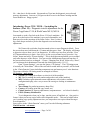
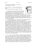
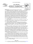
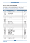
Drawn from a pair of ENX Articles written by The Parts Drop…
Introducing: Xerox C118 / M118… Scratching the
Surface. (PART I) Introduction & Status Code Meanings
for the Xerox CopyCentre C118, & WorkCentre M118,
M118i.
Xerox C118
These machines are still being placed today by Authorized Dealerships
nationwide… they’re selling strong and I suspect for good reason. These models were
released originally in 2004 but new ones are still available from Xerox. I thought at first that
the machines were Fuji Xerox engines, but now that I’ve seen how the diagnostics work… I
have my doubts. The logic is different from the usual (it reminds me more of the Toshiba
equivalent machines Xerox has sold in the past). So far I’m not aware of any crossovers to
other makes. Folks are telling me that these are machines they want to support... so let’s get
started.
Physically, they are very closely related to the C123/128/133, M123/128/133, &
Pro123/128/133… also the Phaser 5500, however, the Status Codes and Diagnostics are
surprisingly very different between the two groups of models. This article will focus on the
C118 style and we’ll hit on the C123 style in a future article.
These machines are rated to handle a volume of up to 50K pages per month and they
run 18 pages per minute. They range from $1348.- for the stripped down version of the C118
to $3249.- for a loaded M118i.
The Toner Cartridges have a stated yield of 11K prints… They sell under the Reorder
# 6R1179 for around $75.- per cartridge. The C123/128/133 cartridges look the same, but
they yield 30K, and sell for $155.- (6R1184). No doubt the “CRUM”(Customer Replaceable
Unit Monitor) chip has a different ID, so the machine can tell if you put the wrong one in
there.
This machine uses a new type of CRUM… instead of using Connectors, it uses a radio
feedback chip which makes no physical connection at all. I can’t help but call it the “Star
Wars” chip because it reminds me of the Star Wars figures which came out a few years ago.
Those toys had a similar technology. The figures came with chips, and then there was an
electronic toy sold which could tell which chip was placed on it and it’d play back sound clips
relating to the character the chip belonged to. They take it a step further in the copiers
though… the machine can write to the chip as well as being able to read it.
They have come up with a new name for the Drum Cartridges this time around… the
Service Manual refer to them as “Xero/Developer Cartridges”. They have a yield of 60K and
retail for $199.- (13R589). The C123/128/133 machines use the same cartridge as the C118 /
M118. Like the Toner Cartridges, these Drum Cartridges also use the new ‘Star Wars’ type of
CRUM chip.
The Fuser is supposed to run for around 175K, although I’m told many of them
require work or replacement considerably before the count runs out. According to the parts
list I have here, none of the fuser parts are spared… so you have to replace the whole darned
thing even if it’s just a gear which needs replacing. That’ll remain true for a little while…
until someone goes and makes some good aftermarket parts for repairing the fusers.
www.partsdrop.com - Page 1 of 10
The Status Codes at first glance looked different from other Xerox models I’m
familiar with… In the Service Manual, they are a letter followed by one number, then a dash
followed by 4 digits. Looking more closely, I can see that if you drop the last three ‘0’s in the
subcode, the codes follow a familiar pattern after all (U4-1 for example instead of “U41000”). I suspect that the machine may actually display only the first digit of the subcode on
display. So… the machine may actually show “C1-3” instead of “C1-3000”. The code
meanings stays consistent with older models: The Status Codes which start with “C” are still
paper jam related and the J1 is for the toner, and U4 is for fuser problems… Sound familiar?
Here’s a list of the Status Codes and roughly what they mean. There are a bunch of
Fax related codes which we won’t cover here since the list is kind of long for this article.
Status Code
Description
C1-3000 (C1-3) Paper Jam before Registration Sensor. (when feeding from Tray 1)
C2-2000 (C2-2) Paper Misfeed before Tray 2 Feed Sensor.
C2-3000 (C2-3) Paper Jam before Registration Sensor. (when feeding from Tray 2)
C3-1000 (C3-1) Paper Misfeed before Tray 3 Feed Sensor.
C3-3000 (C3-3) Paper Jam before Registration Sensor. (when feeding from Tray 2)
C4-0000 (C4-0) Paper Misfeed before Tray 4 Feed Sensor.
C4-1000 (C4-1) Paper Jam before Tray 3 Feed / Vertical Transport Sensor. (when
feeding from Tray 4)
C4-2000 (C4-2) Paper Jam before Tray 2 Feed / Vertical Transport Sensor. (when
feeding from Tray 4)
C4-3000 (C4-3) Paper Jam before Registration Sensor. (when feeding from Tray 4)
C6-1000 (C6-1) Paper Jam before Registration Sensor. (when feeding from Duplex)
C6-2000 (C6-2) Paper Jam before Registration Sensor. (when feeding from Duplex...
non-stop)
C8-2000 (C8-2) Paper Jam… Tray 2 Feed / Vertical Transport Sensor did not deactuate.
C8-3000 (C8-3) Paper Jam… Tray 3 Feed / Vertical Transport Sensor did not deactuate.
C8-4000 (C8-4) Paper Jam… Tray 4 Feed Sensor did not deactuate.
C8-6000 (C8-6) Paper Jam… Duplex Feed Sensor did not deactuate.
C9-3000 (C9-3) Paper Jam… before Registration Sensor (when feeding from the
Manual Bypass Tray (MPT)).
E1-1000 (E1-1) Paper Jam… Registration Sensor did not deactuate.
E1-2000 (E1-2) Paper Jam before Exit Sensor
E1-6000 (E1-6) Paper Jam… Paper remains on the Registration Sensor
E3-1000 (E3-1) Paper Jam… Fuser sensor did not deactuate in time.
E3-6000 (E3-6) Paper Jam… Fuser sensor did not deactuate in time.
E8-2000 (E8-2) Paper Misfeed when feeding from the Duplex.
H1-2000 (H1-2) Tray 2 lift failure, or the Tray 2 size switch detected no tray present.
H1-3000 (H1-3) Tray 3 lift failure, or the Tray 3 size switch detected no tray present.
H1-4000 (H1-4) Tray 4 lift failure, or the Tray 4 size switch detected no tray present.
H2-7000 (H2-7) Duplex Module communication failure.
H3-1000 (H3-1) Offset Catch Tray home position failure.
H4-1000 (H4-1) Tray 1 paper size detection problem.
H4-2000 (H4-2) Tray 2 paper size detection problem.
H4-3000 (H4-3) Tray 3 paper size detection problem.
www.partsdrop.com - Page 2 of 10
H4-4000 (H4-4)
H7-3000 (H7-3)
H7-4000 (H7-4)
H7-7000 (H7-7)
H7-8000 (H7-8)
H8-1000 (H8-1)
H8-2000 (H8-2)
H8-3000 (H8-3)
H8-4000 (H8-4)
H9-3000 (H9-3)
H9-4000 (H9-4)
H9-7000 (H9-7)
J1-2000 (J1-2)
J3-1000 (J3-1)
J4-1000 (J4-1)
J6-1000 (J6-1)
J7-1000 (J7-1)
J7-2000 (J7-2)
J7-3000 (J7-3)
J8-1000 (J8-1)
J8-2000 (J8-2)
J8-3000 (J8-3)
S1-0000
S1-0001
S1-0010
S1-0011
S1-0012
S1-0013
S1-0014
S1-0015
S1-0016
S1-0020
S1-0021
S1-0022
S1-0023
S1-0024
Tray 4 paper size detection problem.
Two Tray Module (2TM) data error detected in the 2TM board.
Two Tray Module memory read / write error.
Two Tray Module communication error.
Invalid tray module detected.
Tray 1 paper size switch failed.
Tray 2 paper size switch failed.
Tray 3 paper size switch failed.
Tray 4 paper size switch failed.
Single Tray Module (STM) memory problem detected.
Single Tray Module (STM) memory read/write problem.
Single Tray Module (STM) communication error.
Toner Cartridge empty.
Xero/Developer cartridge (Drum Ctg.) not installed.
Auto Toner Control (ATC) sensor failure.
Xero/Developer cartridge (Drum Ctg.) end of life.
Xero/Developer cartridge (Drum Ctg.) CRUM Chip communication
failure.
Xero/Developer cartridge (Drum Ctg.) CRUM Chip write failure.
Xero/Developer cartridge (Drum Ctg.) CRUM Chip is invalid or the
wrong type (ID failure).
Toner Cartridge CRUM Chip communication failure.
Toner Cartridge CRUM Chip write failure.
Toner Cartridge CRUM Chip is invalid or the wrong type (ID failure).
Carriage motion problem.
Document Feeder top cover opened during scanning from the platen
glass.
Document Misfeed (ADF) – The Document Feed Sensor did not see the
document being fed in.
Document Jam (ADF) – The Document Lead Edge Sensor did not
detect the document in time.
Document too long… or Lead Edge Sensor did not deactuate on time.
Document too short…
Document jam (ADF). Document remains on both document sensors.
Document platen opened during Document Feeder (ADF) scan.
Document Feeder top cover opened during Document Feeder (ADF)
scan.
Document Misfeed (DADF) – The Document Feed Sensor did not see
the document being fed in.
Document Jam (DADF) – The Document Lead Edge Sensor did not
detect the document in time.
Document too long (DADF)… or Lead Edge Sensor did not deactuate
on time.
Document too short… (DADF)
Document duplexing jam.
www.partsdrop.com - Page 3 of 10
S1-0025
S1-0026
S1-0027
U0-1000 (U0-1)
U0-2000 (U0-2)
U1-1000 (U1-1)
U3-5000 (U3-5)
U4-1000 (U4-1)
U4-2000 (U4-2)
U4-3000 (U4-3)
U4-9000 (U4-9)
U5-1000 (U5-1)
U5-2000 (U5-2)
U6-5000 (U6-5)
U6-6000 (U6-6)
Z1-0000 (Z1-0)
Document jam (DADF). Document remains on both document sensors.
Document platen opened during Document Feeder (DADF) scan.
Document Feeder top cover opened during Document Feeder (DADF)
scan.
Main motor failed to stop due to a control error.
Network (ESS) image ready timed out.
Main Motor failure.
ROS (Raster Output Scanner or Laser Unit) Motor failure.
Fuser failure (did not come up to temperature in time)… must be reset
from diagnostics (NVM code 50-20 must be reset to ‘0’)*.
Fuser over temperature…. Must be reset from diagnostics (NVM code
50-19 must be reset to ‘0’)**.
Fuser thermistor circuit is detected as being an open circuit.
Fuser fan failure. (the fan should be turning at power on).
Toner dispense motor failure.
RAM read / write failure.
Memory failure due to low power condition.
CRUM control ASIC has failed.
Billing counter failure.
That does it for the Status Codes. We’ll get into the diagnostic tests and adjustments next
article. I won’t leave you completely hanging though… You’ll need to get into diagnostics in
order to clear the Fuser Codes (U4-1 & U4-2). Here’s how to do that:
Entering Diagnostic Mode: From the powered on state, hold down the ‘0’ button and then
press ‘Start’. The display will change to opposite colors to show you it’s in diagnostics. If it
fails to go in at first, press the ‘Clear All’ button and then try it again. You can run copies
from the diagnostic mode. Once you’re in, there is a “Main Menu” (CE Setting), so you’ll
need to select the appropriate menu option (most of the stuff is in the option “Chain-Function”
including component tests and memory read / write). To exit diagnostics when you’re done,
turn the power off and back on.
* Clearing the U4-1000 (U4-1) Status Code: Enter diagnostics… Select ‘Chain-Func’ in the
‘CE Setting’ screen by using the ‘Select’ button, followed by ‘Enter’. Select “NVRAM
R/W”. Enter the “Chain” (in this case ‘50’). Next select “Func” (function) by using the
“Select” button. Enter the “function”: ‘20’ followed by ‘Start’. The current value for that
memory code (50-20 in this case) will appear in the “Read” column (if the machine is in a
U4-1 status condition, the value will read as ‘1’). Change the value by pressing the “Select”
button at the “Read” column to switch to “Write”. Enter a ‘0’ for the new value, and then
press ‘Start’. Finally, select “Write NVM”.
* Clearing the U4-2000 (U4-2) Status Code: Enter diagnostics… Select ‘Chain-Func’ in the
‘CE Setting’ screen by using the ‘Select’ button, followed by ‘Enter’. Select “NVRAM
R/W”. Enter the “Chain” (in this case ‘50’). Next select “Func” (function) by using the
“Select” button. Enter function ‘19’ followed by ‘Start’. The current value for that memory
code (50-19 in this case) will appear in the “Read” column (if the machine is in a U4-2 status
condition, the value will read as ‘1’). Change the value by pressing the “Select” button at the
“Read” column to switch to “Write”. Enter a ‘0’ for the new value, and then press ‘Start’.
Finally, select “Write NVM”.
www.partsdrop.com - Page 4 of 10
Ok… that does it for this month. Next month we’ll get into the diagnostic test codes and
memory adjustments. Later on we’ll figure out how to service the Drum Cartridge and the
Fuser Module too. Happy repairs!
Introducing: Xerox C118 / M118… Scratching the
Surface: (Part II) - Diagnostic tests & adjustments for the
Xerox CopyCentre C118, & WorkCentre M118, M118i.
Last month we took a first look at the Xerox C118 style machines. We
got as far as the basics of the machine’s specs and consumables, and
then moved on to the meanings of the Status Codes. Now it’s time to
dig a little deeper and take a peek at the diagnostic tests and memory
adjustments.
Xerox C118
We’ll start with a refresher from last month on how to enter Diagnostic Mode: From
the powered on state, hold down the ‘0’ button and then press ‘Start’. The display will change
to opposite colors to show you it’s in diagnostics. If it fails to go in at first, press the ‘Clear
All’ button and then try it again. Once you’re in, the service manual says to press the “Log
In/Out” button and select “System Settings”. This is the highest menu and the service manual
only talks about two of the choices. You can reset the Administrator Password from here if
the password has been lost or changed… Choose “Changing Pass Word” followed by “Enter”,
you can change the Administrator Password (the default password is ‘11111’).
From “System Settings”, you can also choose “CE Settings”. The CE Settings menu
is basically the “Main Menu”. Most of the stuff which would interest you and I, will be found
in the “Chain-Function” menu including component tests and memory read / write functions.
The menus within the CE Setting menu are arranged as follows:
CE Settings – main menu:
• Version (for reading the software revision level of the machine)
• MC. No (for reading the serial number and product code of the machine)
• MFC (Includes registration and scanner adjustments, soft switches, machine
configuration display, also a way to move the carriage to locking or maintenance
position.)
• Trace Dump (for producing memory dump files)
• Counter (for reading print and copy counts, etc.)
• Chain-Function (for memory adjustments, component tests… see below for details)
• P-ESS (Memory initialization
To exit diagnostics when you’re done, turn the power off and back on. One positive
feature is that you can run copies while still in diagnostic mode… This can be helpful when
you’re making copy quality adjustment since you can produce test copies without having to
leave diagnostics.
Once you are in the “Chain-Function” menu, you’ll see the following submenus:
Chain-Function – sub menu:
www.partsdrop.com - Page 5 of 10
•
•
•
•
•
Test Print
NVRAM R/W (Non Volatile Memory settings Read / Write)
A/D Check (Some sensor reading tests such as the fuser thermistor and paper size
sensors)
IO Check (Input / Output component tests… for sensors, motors, solenoids, etc)
ATC Check (Checks the status of the Automatic Toner Concentration sensor)
The Memory adjustments (NVRAM R/W) are handled by entering diagnostic mode
and then selecting “CE Setting”. Use the ‘Select’ button to scroll to “Chain-Func” and then
press ‘Enter’. Next enter the “Chain” which is the first part of any code (the part before the
dash. For example: for the code 50-20, the number “50” would be the Chain). Then use the
“Select” button to find the function you wish to change (“20” in the current example of 5020). Enter “Func No.” then press ‘Start’ and the current value will show up in the “Read”
column. Press the ‘Select’ button at the “Read” column to switch to “Write”. To change a
value, enter a new value in the “Write” column and press the “Start” button. This will move
the old value up. Select “Write NVM”. If the new value is within the acceptable range, the
system will write the new value into memory.
Following are a bunch of the more useful sounding Memory Adjustments which are
available. Many have been left out since it didn’t seem likely that they’d be useful in the
course of regular field service. I must warn you, the explanations in the Service Manual of
the codes are virtually non-existent, so that even out of the ones I list here, I’m not sure how
you’d use them in a productive way. For example they say “normal” vs. “abnormal” for
things like toner sensing (does the condition “normal” mean yes toner is sensed?… I’d
assume so, but the manual isn’t saying). I also went through the troubleshooting section of
the Service Manual and found very few references to actually using these codes in the
procedures, so I couldn’t draw any conclusions from there.
Here’s a list for what its worth:
ChainFunc
6-52
Name
Image Area
Values
(range)
0-1
default
value
0
0=Normal image area, 1=Wide
image area
0.135mm increments
6-57
Lead Edge Erase offset value
0-99
6-58
Trail Edge Erase offset value
0-99
0
0.135mm increments
6-59
Side Edge Erase
0-16
8
0.254mm increments, 8=2.025mm
6-60
Lead Edge Nominal Erase
0-30
15
0.135mm increments
6-63
Trail Edge Nominal Erase
0-30
15
0.135mm increments
16-33
ATC Setpoint (Auto Toner Concentration)
0-99
55
20-1
Lead Edge Registration (All Trays)
0-66
33
A higher number means the image
will start later on the page. The
range allows nearly 9mm total
adjustment range.
23-20
Simplex / Duplex
0-1
0
0 = Simplex, 1 = Duplex
23-21
Feed Tray
1 to 6
1
23-23
Test Printout Choices
1-4
1
1 =Tray1, 2 =Tray 2, 3 =Tray 3, 4
=Tray 4, 5 =HCF (High Cap
Feeder), 6 =MPT (Manual Paper
Tray)
For setting which test pattern will
print out from "Test Print" in the
"Chain-Function" menu: 1=Stripe,
2= Dark Dusting, 3=Blank, 4=Grid
www.partsdrop.com - Page 6 of 10
0
Remarks
23-24
Image Area
0-1
0
0=Normal image area, 1=Wide
image area, its not clear how this
code is different from code 6-52.
0 = Toner ctg not empty, 1 = Toner
ctg is empty.
CRU=Customer Replaceable Unit
(drum ctg.)
0 = "Normal", 1 = "Abnormal"
27-52
Toner empty (for CRUM read)
0-1
0
31-2
Return Normal CRU Mode
0-1
0
42-10
Toner empty (actual toner sensing)
0-1
0
42-14
Toner Dispense Rate (10mg/s)
0-254
20
42-15
Toner Empty State (NVM, 0 to 3)
0-4
0
42-26
Current Humidity (%)
0-99
-
Percentage
42-3
ATC Judge (Automatic Toner Concentration)
0-1
0
0 = "Normal", 1 = "Abnormal"
42-4
Humidty sensor Judge
0-1
-
42-44
Current Temperature
0-99
-
no details given in the service
manual…?
Degrees Celcius
42-5
Temperature Sensor Judge
0-1
-
This sensor is in the machine's
body, not in the fuser.
43-11
Result of ATC check judgementg
0-4
-
0=Low, 1=Normal, 2=High, 3=Fail,
4=Abnormal End
50-14
Condensation detection
0-1
1
0 = Non-condensation mode, 1 =
Condensation mode
50-15
Enable OCT & Inverter
0-2
1
50-20
FSR Reset Fuser Over Temp
0-99
0
50-21
Plain Paper default weight
0-1
0
0= disable, 1 = Inverter + OCT
(Oscillating Catch Tray), 2 =
Inverter only
0 = reset, 1 = FS1 detectes over
temp., 2 = FS2 detects over temp. 3
= On time fail, 4 = Cold Sagging
Fail (temp dropped during a copy
run)
0=thicker than 70gsm, 1=70gsm or
less
0=disable Tray 4, 1=Enable Tray 4
50-7
Enable Tray 4
0-1
1
53-1
Toner empty (for CRUM read)
0-255
0
Not clear how this code is different
from code 27-52
53-31
Toner empty state (for CRUM read)
0-255
55
53-36
ATC Code (for CRUM read)
0-1
0
Not clear how this is different from
53-1 or 27-52
53-38
ATC Judge (for CRUM read)
0-1
0
53-39
CRU New or Old (for CRUM read)
0-1
0
0=New, 1=Old
. Now for some Input Component Codes… these are for testing sensors, switches, and such.
For some reason, some of the tests are singled out and accessible by choosing “A/D Check”,
while others are accessed by choosing “IO Check”. First, here are the codes available from
“A/D Check”. You choose “A/D Check” from the “Chain-Function” menu, then enter the test
code you want to run. The values which you read with these codes are going to have little
meaning unless you have another machine handy which is behaving itself to compare results
with.
Here’s a list:
ChainFunc
Name
Values
(range)
Remarks
7-1
Tray1 Size Sensor
0-1023
Current Tray 1 Size Auto Detect value
7-2
Tray 2 Size Sensor
0-1023
Current Tray 2 Size Auto Detect value
7-3
Tray 3 Size Sensor
0-1023
Current Tray 3 Size Auto Detect value
7-4
Tray 4 Size Sensor
0-1023
Current Tray 4 Size Auto Detect value
7-6
MSI Size Sensor
0-1023
Current MSI Size Auto Detect value
9-30
BTR Monitor (voltage input)
0-1023
www.partsdrop.com - Page 7 of 10
10-20
Fuser Thermistor (control sensor)
0-1023
Standy fuser temperature monitor
15-60
Temperature Sensor
140-710
This sensor is in the machine's body, not in the fuser
15-61
Humidity Sensor
36-400
15-62
ATC Sensor
200-800
The rest of the Component Control codes and “Special Tests” are accessed by choosing “IO
Check” from the “Chain-Function” menu. Enter the code of the component you want to
check or activate. For Input Component Codes (switches, & sensors), when you press ‘Start’,
the machine will read the component’s state at that moment and display it on the control
console (H for High, L for Low). The state will not change on the display automatically as
the state of the component changes… you would have to hit ‘Start’ again to read the sensor
again. For output components (motors, solenoids, clutches, etc), the component will activate
for a period of time whenever you hit ‘Start’.
Chain-Func
Name
Notes
Test
Type
Output
4-1 *
Main Motor
4-2
Fuser Fan Motor (high speed)
The following voltages will be turned on
simultaneous along with the Main Motor: Bias
Charge Roll AC, Bias Charge Roll DC,
Developer DC, and Bias Transfer Roll output.
*
6-15
ROS (Laser Unit) Motor
7-19
Tray 2 Lift Motor (feed motor reverse)
Turns on Lift Motor when Tray 2 lift sensor
reads "L" (low). Motor stays still if lift sensor
reads "H" (high).
Output
7-20
Tray 3 Lift Motor (feed motor reverse)
Turns on Lift Motor when Tray 3 lift sensor
reads "L" (low). Motor stays still if lift sensor
reads "H" (high).
Output
7-21
Tray 4 Lift Motor (feed motor reverse)
Turns on Lift Motor when Tray 4 lift sensor
reads "L" (low). Motor stays still if lift sensor
reads "H" (high)
Output
Output
Output
8-2
Takeaway Motor
Output
8-12
Tray 1 Feed Motor Clutch
Output
8-13
Tray 2 Feed Motor Clutch
Output
8-14
Tray 3 Feed Motor Clutch
Output
8-15
Tray 4 Feed Motor Clutch
Output
8-17
SMH Feed Clutch
8-18
Two Tray Module Takeaway Clutch
Output
8-24
Single Tray Module Takeaway Clutch
Output
8-38
Up Motor
Output
8-44
Tray 3 Feed Motor
Output
8-45
Tray 4 Feed Motor
Output
8-46
Single Tray Module Takeaway Motor
Output
8-50
Up Motor
9-23
Bias Charge Roll AC Bias
Output
9-24
Bias Charge Roll DC Bias
Output
9-29
Bias Transfer Roll (+) Bias
Output
9-33
Developer DC Bias
Output
The acronym list in the manual isn't saying
what SMH stands for.. Best guess: Special
Media Handler (envelopes, etc).
Rotates for sending paper out to registration
www.partsdrop.com - Page 8 of 10
Output
Output
9-36
Bias Transfer Roll (-)
Output
10-3
Oscillating Catch Tray Home Check
Output
10-4
Fuser Fan Motor (high speed)
Output
10-5
Oscillating Catch Tray Return & Preoffset move
Output
10-8
Exit Drive Motor, Forward
Output
10-9
Exit Drive Motor, Reverse
Output
10-10
Exit Motor
Output
10-51
Exit Gate Solenoid
Output
10-61
Offset Motor 1 Center
Output
10-62
Offset Motor 1 Forward
Output
10-63
Offset Motor 1 Reverse
Output
15-63
Dispense Motor
1-1
Left Cover Interlock Switch
L = Cover open / switch off
Input
1-10
Tray Module Cover Interlock Switch
L = Cover open / switch off
Input
1-11
Lefthand Lower Cover Interlock Switch
H = Cover open / switch off
Input
1-12
Front Cover Interlock Switch
L = Cover open / switch off… Note that if the
Left Cover is open
Input
7-5
Tray 4 Size Sensor
7-7
Tray 1 Paper Empty Sensor
L = No Paper
Input
7-8
Tray 2 Paper Empty Sensor
L = No Paper
Input
7-9
Tray 3 Paper Empty Sensor
L = No Paper
Input
7-10
Tray 4 Paper Empty Sensor
L = No Paper
Input
7-12
Special Media Handler (SMH) /
Envelope Paper Empty Sensor
L = No Paper
Input
7-14
Tray 2 Lift Sensor (stack height sensor)
L = Tray sensed in Up Position
Input
7-15
Tray 3 Lift Sensor (stack height sensor)
L = Tray sensed in Up Position
Input
7-16
Tray 4 Lift Sensor (stack height sensor)
L = Tray sensed in Up Position
Input
Output
Input
7-26
Tray 1 Size Sensor
Input
7-27
Tray 2 Size Sensor
Input
7-28
Tray 3 Size Sensor
Input
8-5
Registration Sensor
L = Paper Detected
8-6
Feed out #2 Sensor
L = Paper Detected
Input
8-8
Takeaway Feed Out Sensor #3
L = Paper Detected
Input
8-9
Takeaway Feed Out Sensor #4
L = Paper Detected
Input
8-31
Duplex Wait Sensor
L = Paper Detected
Input
Input
8-32
Duplex Registration Sensor
H = Paper Detected
Input
8-33
Duplex Interlock Switch
H = Duplex Open
Input
8-35
Registration Clutch
L = Clutch is on
Input
8-47
Feed Ready Signal
H = level is high
Input
8-48
Takeaway Feed Output #3 Sensor
L = Paper Detected
Input
8-49
Takeaway Feed Output #4 Sensor
L = Paper Detected
Input
9-2
Drum Cartridge Detect
L = Cartridge Detected
Input
10-11
Oscillating Catch Tray (OCT) Home
Position Sensor
OCT1 is at its home position
Input
10-23
Exit Sensor
L = Paper Detected
Input
20-5
Manual Paper Tray (MPT) Side GuideSet Minimum Position
Put the Side Guide to minimum size and
execute to set the minimum position in
memory
Special
www.partsdrop.com - Page 9 of 10
20-6
Manual Paper Tray (MPT) Side GuideSet Maximum Position
20-58
MCU NVM (Non Volatile Memory)
23-10
Test Print
Put the Side Guide to maximum size and
execute to set the minimum position in
memory
Resets the Main Controller Unit's Memory to
defaults
Special
Prints a test pattern (default pattern is bands)
Special
Special
23-13
Tone Up
Special
23-14
Tone Down
Special
43-1
Automatic Toner Control (ATC) Check
The machine reads the ATC sensor and
stores a target value, an output value and a
decision.
Special
* For some reason, there are several codes listed for the “Main Motor” including 4-1, 8-1, 9-1,
10-1. The Service Manual does not explain the differences.
That just about does it for the C118 style. Next month, we’ll take a look at the C123
style machines (C123, C128, C133, M123, M128, M133, Pro123, Pro128, Pro133) which
look very similar at first glance and actually share the same part number for the Drum
Cartridge. As it turns out, they are actually quite different, particularly when it comes to
status codes and diagnostics. The word on the street is that the C123 style is actually a very
good solid bunch of machines, so I’m looking forward to meeting them.
Britt works for The Parts Drop, a company whose primary business is providing parts,
supplies and information for Xerox brand copiers, printers and fax machines. You can find
more information, including many of Britt’s past ENX articles on their website,
www.partsdrop.com. If you’d like to read more about Xerox brand office equipment, there’s
also a complete listing of past articles under contributing writers on the ENX website
(www.ENXMAG.com).
www.partsdrop.com - Page 10 of 10