1
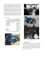
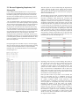
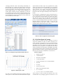
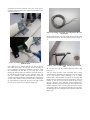
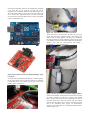
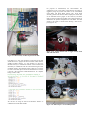
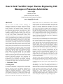
How to Hack Your Mini Cooper: Reverse Engineering CAN Messages on Passenger Automobiles Jason Staggs University of Tulsa Institute for Information Security Crash Reconstruction Research Consortium [email protected] ABSTRACT With the advent of modern vehicular technology, the computerized components of passenger vehicles have become increasingly interconnected to facilitate automotive efficiency, driving experience, and emissions control. Controller Area Networks (CANs) are well suited for intercommunications among these components, called electronic control units (ECUs). ECUs are used to communicate with critical control systems on automobiles including transmissions, braking, body control, and even vehicle infotainment systems. CAN networks are designed for high speed, reliable communications between ECU components operating in harsh environments. Unfortunately, the security of the underlying protocol is dubious at best. The Bosch CAN standard does not include inherent security mechanisms for authentication and validation of messages sent to various ECUs over a CAN network. Currently the only data security methods for CAN networks on passenger vehicles are the use of proprietary CAN message IDs and a physical boundary between the CAN bus and the outside world. This presents a serious security issue, because anyone with physical access to the vehicle's data bus could generate spoofed CAN traffic destined for various ECUs, some of which could be responsible for critical vehicle operations such as the braking system or engine control unit. To prevent this, manufactures of passenger vehicles do not publish the proprietary CAN message IDs for various components on the vehicle network. However, proprietary message IDs can be identified through a reverse engineering process. This paper identifies techniques for reverse engineering CAN messages on passenger vehicles, demonstrating the ease with which an attacker could manipulate CAN-enabled components of an automobile. The reverse engineering methodology is demonstrated by the transformation of the speedometer and tachometer (instrument cluster) of a 2003 Mini Cooper into a functional clock controlled via spoofed CAN messages sent by an Arduino microcontroller. 1. INTRODUCTION 1.1 Background As automobile components become increasingly computerized, inter-device communication is imperative for overall vehicle efficiency, emissions control, and diagnostic maintenance. In 1986, Bosch introduced the Controller Area Network (CAN) standard for automobile manufactures, in order to facilitate communication between microcontrollers on automobiles [1]. The CAN standard was designed as a multi-master broadcast serial bus, used to interconnect electronic control units (ECUs). At the physical layer, frame bits are encoded in a non-return to zero (NRZ) format over the wire, and facilitates the use of automatic collision detection with arbitration. Essentially, any message sent out by any node on a CAN network will be seen by all other nodes [4]. European manufactured automobiles were early adopters of CAN networks. However, since 2008, all cars sold in the U.S have been required to implement the CAN standard for EPA mandated diagnostic purposes. Newer cars manufactured today have an average of at least 70 ECUs for various subsystems. Instead of wiring individual computerized components together to form a complex mesh-style network topology, CAN allows for a more streamlined bus-style topology. This drastically reduces the amount of required wiring and allows for devices to communicate with one another more efficiently. ECUs in vehicles are inherently engineered for vehicle safety as the number one priority. Unfortunately, most of these components have not been designed with the consideration of an adversary with malicious intentions, whom has physical access to the vehicle. Although others may have dismissed the likelihood of the threat of physical access, it is still an important attack vector to consider. Current research in the areas of automotive computer security shows that these systems are not designed with any form of access control, allowing anyone with access to the data bus to wreak havoc on any of the connected systems. In 2010, researchers from The University of Washington and The University of California, San Diego demonstrated such attacks by interfacing with the on-board diagnostics (OBDII) port of a vehicle [2][3]. The researchers were successfully able to take complete control of critical components of the vehicle at rest and in motion by using simple replay attacks and fuzzing techniques over the CAN bus network. The lack of access controls on automobile networks creates an inherent security flaw, allowing for rogue, malicious CAN devices to be attached to the network. These devices could be leveraged in a way that could cause harm to other critical components on the automobile. The structure of a CAN frame is best described by an understanding of the notion of framing, also known as a delineated sequence of bits. The most notable fields in a standard format CAN frame include; Start of Frame (SOF), Identifier, Data Length Code (DLC), Data Field (0-7 bytes), CRC, and End of Frame (EOF). The Bosch CAN standard specifies that standard messages have 11-bit identifiers, which are unique for communicating with the proper CAN component. This field is also used for arbitration purposes such as message priority. Thus, a lower message ID corresponds to a higher message priority. This work analyzes the CAN bus of a 2003 Mini Cooper S which interconnects the instrument cluster, engine control unit, anti-lock braking system, steering angle sensors, and other systems (Figure 1-1). Since the message identifiers for the Mini Cooper are manufacture proprietary information, a methodology for reverse engineering CAN message identifiers is presented. Potential attack strategies are demonstrated, to show how an attacker could manipulate the interconnected components on the CAN bus. The reverse engineering method is used to build a CAN clock from scratch, using the instrument cluster of a 2003 Mini Cooper S that was involved in a staged auto collision with a GMC Envoy (Figure 1-2). This paper concludes with a discussion of the future of communication security for passenger vehicles and the security engineering mechanisms that should be considered early on in the development life cycle of ECUs and associated vehicle networks. Figure 1-1: Mini Cooper Data Network Figure 1-2: Wrecked 2003 Mini Cooper and Instrument Cluster Unit 2. PROCEDURE This section describes a methodology for reverse engineering proprietary CAN message IDs on passenger vehicles. We provide an example by using the CAN data log captured from a 2003 Mini Cooper that was involved in a staged vehicle collision. Next we demonstrate a proof of concept using the reverse engineered CAN IDs to manipulating the car's instrument cluster to generate artificial vehicle and engine speed CAN traffic to the instrument cluster (speedometer and tachometer). 2.1 Reverse Engineering Proprietary CAN Message IDs Unlike commercialized standards that run on top of CAN and leverages the CAN extended format that have well documented information regarding their component IDs such as SAE J1939, the Bosch CAN standard format only specifies how the protocol should work, but remains mute on what values should be used for particular CAN devices. The CAN standard format 11 bit message identifier is of interest to us here because it is the common passenger vehicle application. The ID is often used to determine how ECUs know what message to listen to. The CAN standard format does not define which message IDs are associated with what components, thus leaving the vehicle manufacture to define their own CAN message IDs to control various ECUs. Theoretically the standard format can have up to 2048 unique message IDs present on a CAN network as the standard format allows for 11 bit message IDs. Most actual message IDs used by manufactures of passenger vehicles such as GM, BMW, Ford, Honda, etc. are proprietary and this information is not made publicly available by automobile manufactures. Thus, a process is needed to reverse engineer these IDs to tie them to their actual components. This data capture ran for 90 seconds during the staged head on collision involving the Mini Cooper. During that 90 seconds, about 107,000 CAN messages were recorded off of the CAN bus. This data was saved as a CSV file which allowed for parsing the data in several different ways. With the data log capture in hand, we needed a method to isolate the CAN message IDs that were of interest to us. Since we were interested in identifying which message IDs correspond with displaying vehicle and engine speed to the instrument cluster, we attempted to identify the IDs responsible for controlling the speedometer and tachometer. Initial observations of the raw data revealed that some IDs were present more often than others. That is, some message IDs are transmitted more frequently across the CAN bus over the duration of the capture. Initially, we hypnotized that the message IDs responsible for updating the vehicle and engine speed display gauges would be updated more frequently than other devices, thus having a lower message ID compared to other messages. Running a simple Bash script we parsed the data to identify only the unique message IDs and how often they were transmitted over the CAN network (Figure 2-2). During the staged crash of the Mini Cooper, a CAN data logging device was used to passively capture all CAN messages traversing across the network. Information that was captured included a timestamp, DLC, ID, and the data fields for each CAN messages (8 bytes) (Figure 2-1). Figure 2-2: Top 7 most frequently occurring messages on the CAN data bus Surprisingly, there were only 15 unique message IDs present on the CAN bus. Since there were only 15 message IDs on the bus we inferred that one of these messages was responsible for controlling the display gauges on the instrument cluster. The question now became a matter of which message ID, and which byte, or bit will need to be manipulated in order to achieve our desired effect? Now that we had an idea of the possible suspect message IDs, we needed to figure out which byte offsets are used that contain the vehicle and engine speeds. Figure 2-1: CAN data log Each byte holds a value of up to 0xFF or 255 in decimal. The trick is to find which byte, bit, or combination of bytes are responsible for controlling the gauges. To do this we use a method for visually correlating physical system interactions with identifiable patterns. Essentially, we visualize the data values in each byte against the corresponding time stamp of the message throughout the duration of the data capture (90 seconds). Considering humans are inherently good at recognizing patterns, plotting each byte against the timestamp helps us identify a change in speed with the help of a scatter plot line graph. Using this method we graphed all bytes, individually, to identify recognizable patterns corresponding to a steady increase in data values over time, which was indicative of the vehicle speed for this staged automobile collision. Leveraging Microsoft Excel’s data plotting functionality, we filtered the data set to explicitly show data related to message ID 0x153 and then plotted each byte separately (Figure 2-3). Figure 2-4 show byte offset 2 from message ID 0x153 going from 0 to about 30 MPH starting at 75 seconds and then stopping at 90 seconds. (When collision occurred). Additionally, we also have prior knowledge from other external instruments attached to the car during the staged crash, that the top speed before impact was around 30 MPH so we know that message 0x153 byte offset 2 has to be associated with vehicle speed. speed. Because the Mini Cooper was propelled with a pulley system in the staged crash in which the data log was recorded, the actual engine speed was at a constant idle speed throughout the capture. Because of the engine speed being idle during the experiment, our previous method of visually identifying message IDs based on data value against timestamps will be ineffective for this ID. For the purposes of identifying the engine speed message ID, a series of fuzzing techniques were performed in which case all of the 15 unique ID's 8 byte data fields were fuzzed with arbitrary data. This brute force process was used until we witnessed the needle on the tachometer spinning arbitrarily. Using this iterative process, we find that message ID 0x316, byte offset 3, controls the tachometer display of engine speed. Table 2-1 shows the CAN message IDs that we were able to isolate to a device on the instrument cluster from the Mini Cooper CAN bus. Table 2-1: Reverse engineered CAN message IDs 2.2 CAN Clock Proof of Concept In this section we describe the steps in creating our proof of concept that simulates the effect an attacker could have on a vehicle, assuming she has physical access. In this demonstration we transform the speedometer and a tachometer from a wrecked 2003 Mini Cooper S into a literal clock, where the hours will be represented by the speedometer (0-120 MPH) and the minutes will be represented by the tachometer (0-6000 RPM). We build a CAN network with three physical CAN nodes. We generate CAN traffic by building a CAN ECU using an Arduino microcontroller, MCP1215 CAN controller, and MCP2551 CAN transceiver. Figure 2-3: Plotting data log ID and data fields with Excel Figure 2-4: Wheel speed vs. time Now that we have identified the message ID and byte offset for vehicle speed, we need to isolate the ID and data fields for engine Hardware Supplies Arduino Uno "REV 3" CAN-BUS Shield Real Time Clock Module 2 x 120 ohm resistors 18 gauge twisted pair wire "CAN bus backbone" Wire nuts Tie wraps 12V DC power source Mini Cooper S Instrument Cluster 18” x 14” board 2 x 1.5” x 1.625” x 1.25” brackets with bolts The first thing we did was mount the hardware onto a selfcontained board. For prototyping purposes we used an 18” x 14” wood board to house the platform of our CAN clock. Next we needed to mount the Mini Cooper gauges using brackets, screws, and bolts (Figure 2-5). Figure 2-6: 18 gauge twisted pair wire being used for the CAN bus backbone We also terminate both ends of the twisted pair wire by using 120 Ω terminating resistors at each end to reduce reflection (Figure 27). Figure 2-5: Mounting Mini Cooper instrument cluster to platform board Since BMW does not publicly disclose CAN message IDs for their various ECU devices on passenger vehicles, we apply our reverse engineering methodology described in section 2. Using this methodology, we now have a pretty solid idea of what message IDs and byte offsets are needed to control the display of the speedometer and tachometer on the instrument cluster. The next step is building a small CAN network and a CAN node capable of introducing messages onto the data bus. The first thing we need to do is build the CAN bus infrastructure. In adhering to the CAN standard, we used about 18 inches of 18 gauge twisted pair wire for the actual CAN bus backbone (Figure 2-6). Figure 2-7: Wire terminated with 120 ohm resistors on both ends We now have our CAN bus backbone built and ready to add nodes onto it. Next we attach the Mini Cooper instrument cluster (which includes both the speedometer and tachometer) onto the network via its CAN data lines. When attempting to use or modify hardware that is either unfamiliar or unknown, the first thing that should be done is referencing the electrical schematics, if they are available. In this case we were able to utilize the Mini Cooper electrical schematics from Mitchell1 (www.prodemand.com). Mitchell1 maintains an enormous repository full of vehicle service manuals, diagnostic codes, and wiring schematics for a majority of passenger vehicles. Leveraging this information was necessary for identifying the wires coming off of the instrument cluster units (Figure 2-8). Figure 2-8: Wires coming off of the Mini Cooper instrument cluster Looking through the 2003 Mini Cooper S service manual, we come across the Instrument Cluster Circuit (IKE). In looking at the electrical wiring schematics, we are interested in identifying wires responsible for 3 things; power, ground, and CAN data. The CAN data wires are obviously distinguishable as being the only twisted pair wires within the mesh of wires. Wires Associated with Power Wire 1 BRN/BLK = Ground Wire 2 VIO/BLK = 12V power source (HOT IN ACCY, RUN AND START) Wire 3 BLK/VIO = 12V power source (HOT IN START) Wire 15 RED/YEL = 12V power source (HOT AT ALL TIMES) Wire 16 GRN/BLU = 12V power source (HOT IN ON OR START) CAN Data Lines Wire 13 YEL/BRN = CAN-L Wire 26 YEL/BLK = CAN-H Once these wires were each identified, we striped the wires, spliced, and soldered them together accordingly. We striped the ends off of the 12V DC power source and tied wires 2, 3, 15, and 16 of the instrument cluster unit to the positive lead of our power source (Figure 2-9). We also tied Wire 1 (ground) to the negative lead on our power supply. Next we connect the CAN high and low data lines to the network. We splice wires 13 and 26 from our instrument cluster into the CAN bus. Notice in Figures 2-9, CAN low is the blue wire of the CAN bus and CAN high is the tan. After capping our wire leads to both power source and splicing CAN node entry points, we can plug in the power source to test that the instrument cluster powers on and works properly. If all goes correctly a chime can be heard as soon as power is applied. Figure 2-9: Splicing instrument cluster wires together with CAN bus and 12V power source Now that the instrument cluster has successfully been connected to the CAN bus, we can configure the node that will be responsible for transmitting data to the instrument cluster unit. This node will be acting as a rogue device that an attacker could use to interact with components on the CAN bus in nefarious ways. We will be using an Arduino Uno Rev 3 and a CAN-Shield to achieve this (Figure 2-10). Figure 2-11: CAN shield used to connect to CAN bus The Arduino will be powered from the same 12V DC power source that powers the instrument cluster. The Arduino Uno features a built in voltage regulator at the power port. Considering the safety benefit of the voltage regulator, applying 12V of power to the Arduino was not an issue as the Arduino Uno specifications explicitly state that the microcontroller can handle a recommended 7 - 12 volts (Figure 2-12). Figure 2-10: Arduino Uno and CAN shield simulating a rogue CAN device To interface the CAN shield with the data bus, we will be splicing the 18 gauge twisted pair wire from the CAN bus and soldering CAN-H and CAN-L wires coming into the pins on the CAN shield as shown in Figures 2-11. Figure 2-12: 12V power source and Arduino voltage regulator In order for the Arduino to keep track of accurate time, even when the power is disrupted, we will use a real time clock module (RTC). The RTC chip is powered with a small battery in order to retain the current time in the event of power loss. The Arduino will poll the time from the RTC in order to transmit the accurate time to the instrument cluster gauges. For demonstration purposes, we placed the RTC on a bread board separate from the Arduino (Figure 2-13). For purposes of demonstration, the microcontroller was configured to work in two modes of operation that can easily be toggled by using the joystick click button on the CAN-Shield; Clock Mode, and Demo Mode (Figure 2-14). Clock mode obviously polls the time from the RTC to display the current time on the instrument cluster gauges via the CAN bus, and demo mode is used to increment the needles on the gauges arbitrarily to demonstrate the dynamic manipulation of CAN traffic. The final product (CAN Clock) is shown below showing a time of 2:47 p.m. (Figure 2-15). Figure 2-14: Joystick button used to toggle between clock mode and demo mode Figure 2-13: RTC used by Arduino to poll accurate time Everything up to this point should be connected, and all that should be left is to program the microcontroller. Other than the standard Arduino libraries, we will primarily be using the MCP2515 library to communicate with the CAN controller, and SPI library to communicate with the CAN shield using the serial peripheral interface. The MCP2515 library allows us to construct our own CAN Frame objects that can be transmitted over onto the CAN bus. (See http://tucrrc.utulsa.edu/canclock/ for complete listing of source code) We will also be using the Wire.h and RTClib.h libraries to communicate with the RTC module. Figure 2-15: Mini Cooper CAN clock final product 3. DISCUSSION 4. CONCLUSION The CAN clock proof of concept demonstrates how easy it could be for an attacker to manipulate ECM components on passenger vehicles. As newer vehicles begin to add more functionality and interconnection options, the attack surface will continue to grow as well. Other research has demonstrated attacks effecting the availability of ECMs on the CAN network. In 2010, researchers at The University of Washington and The University of California, San Diego effectively flooded the CAN network with traffic causing a denial of service (DoS) against all connected components, which rendered much of the car, including the braking system useless [2]. This work described a methodology for reverse engineering proprietary CAN message IDs on passenger vehicles. This methodology is modular enough to be applied to other passenger vehicles with CAN networks. We have demonstrated how to identify message IDs of interest by analyzing CAN data provided by a data log of a 2003 Mini Cooper. We also developed a proof of concept in which we built a CAN network from scratch, and manipulated the Mini Cooper's instrument cluster speedometer and tachometer, turning them into a functional clock. Methods for mitigating spoofed message attacks, and attacks that affect availability of the CAN bus need to be considered when designing and engineering ECUs. To counter the possibility of such attacks, conventional network security concepts, techniques, and devices such as firewalls, and intrusion detection/prevention systems should be considered being applied to CAN. Perhaps some form of a CAN based firewall or anomaly based network intrusion prevention system could be implemented on vehicles that mitigate such attacks from occurring. Although one of the advantages of CAN is for all nodes on the same bus to receive a message, regardless of what device it is intended for, some CAN components should never be allowed to communicate with other CAN components, or at least send certain messages between one another (e.g. infotainment systems to brake controller unit). The notion of a firewall from conventional network security could be applied by using access control lists between various networks, or even ECUs on vehicles. Although it may seem that solving these problems with anomaly based intrusion detection systems could be a trivial method of using existing methods from TCP/IP based anomaly IDSs, it actually would not be as straight forward. Conventional, anomaly based intrusion detection systems are developed and used within a network to detect statistical deviations from prior baselines. However, with the dynamic nature of vehicle networks, there could be numerous instances when otherwise normal activities would violate this baseline due to unexpected physical events, including vehicle collisions, sudden acceleration/deceleration, etc. CAN devices such as ECUs need to have security mechanisms built in that are similarly modeled after modern day computer network security systems such as access control devices, and intrusion detection systems, but not to the extent that they intrude on the reliability of CAN. Finding a compromise between security, reliability, and efficiency of CAN systems are all factors that need to be considered for future research into vehicle network systems. It is well understood that if someone has physical access to a device, all bets are off with regards to security. As such, these vehicle data lines of communication should be considered untrusted and treated as such. Methods of encrypting channels of communication on CAN could be considered, but that would ultimately hinder the speed and reliability advantages provided by CAN. For the time being, automobile consumers have no choice but to rely on physical security of automobiles, and security through obscurity provided by the manufacture proprietary CAN message IDs. Although we are only manipulating the instrument cluster gauges, there is no reason to believe these methods couldn't be applied to other ECMs on the vehicle, including critical devices such as the ABS braking system, accelerator, lighting system, wireless locks, etc. We have thoroughly demonstrated that security through obscurity fails when the attacker has physical access to the vehicle. Future work will look into the areas of monitoring CANs including possibly introducing the use of customized CAN firewalls and intrusion prevention systems. 4. REFERENCES [1] Bosch, C. A. N. (1991). Specification version 2.0. Published by Robert Bosch GmbH (September 1991). [2] Koscher, K., Czeskis, A., Roesner, F., Patel, S., Kohno, T., Checkoway, S., ... & Savage, S. (2010, May). Experimental security analysis of a modern automobile. In Security and Privacy (SP), 2010 IEEE Symposium on (pp. 447-462). IEEE. [3] Checkoway, S., McCoy, D., Kantor, B., Anderson, D., Shacham, H., Savage, S., ... & Kohno, T. (2011, August). Comprehensive experimental analyses of automotive attack surfaces. In Proceedings of the 20th USENIX conference on Security (pp. 6-6). USENIX Association. [4] Davis, R. I., Burns, A., Bril, R. J., & Lukkien, J. J. (2007). Controller Area Network (CAN) schedulability analysis: Refuted, revisited and revised. Real-Time Systems, 35(3), 239-272.