1
O mqm
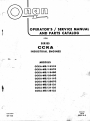
oPERATOR'S / SERVICE ffiANUAL
AND PARTS CATATOG
I
f
FOR
SER I ES
CGKA
IN DUSTRIAL ENGIN
ES
(\-^*-
MODELS
ccKA-MS/ I 831G
ccKA-Iuls/ I 897G
GGKA-MS/ I 949G
ccKA-Ms./20,43G
J
''',,
ccKA-MS/2i I 1G
ccKA.luls/25'67G
cGKA-nt/2Ar 3J
ccKA-MS/31 10J
GGKA-MS/3612J
}
'.!*"'. /
,
s-li
?'.
't
{
q
r6suE 6arE
.12-79
(sPEc G-J)
FORII NUMAER
927-1103
:.r.,..jr::11-
-.;
SAFETY PRECAUTIONS
Always use an appropriately sized, approved
double-throw transfer switch with any standby
generator set. DO NOT PLUG PORTABLE OR
STANDBY SETS DIREETLY INTO A HOUSE
RECEPTACLE TO PROVIDE EMERGENCY
POWER. lt is possible for current to flow from
generator into the utility line. This creates extreme hazards to anyone working on lines to
The lollowing symbols in this manual signal potentially dangerous conditions to the operator or equipment. Read this manual carelully. Know when these
conditions can exist. Then, take necessary steps to
protect personnel as well as equipment.
restore power.
mRN|]{Gl Onan uses this
symbol
throughout this manual to
warn ol possible serlous perco;tal inlury.
mmeq $$r'*TfilH:"'":
-!
Use extreme caution when working on electrical
components. High voltages cause injury or death.
Follow all state and local electricalcodes. Have all
electrical installations performed by a qualified
licensed electrician.
possibre
o Do Not Smoke
Fuels, electrical equipment, batteries, exhaust gases
and moving parts present potential hazards that could
result in serious, personal injury. Take care in lollow-
Lead acid batteries emit a highly explosive
hydrogen gas that can be ignited by electrical
arcing or by smoking.
ing these recommended procedures.
o Use Erlreme Caution
Near Gasoline. A conslant
potential explosive or fire hazard exists.
o
Exhaust Gases Are Toxic
Provide an adequate exhaust system to properly
Do not f ill fuel tank near unit with engine running.
Do not smoke or use open flame near the unit or
the fuel tank.
expel discharged gases. Check exhaust system
Be sure all fuel supplies have a positive shutoff
Be sure the unit is well ventilated.
valve.
Fuel lines must be of steel piping, adequately
'r
While Servicing Batteries
regularly for leaks. Ensure that exhaust manifo[[g,
'1'
are secure and not warped.
Keep The Unil And Surrounding Area Clean
secured and f ree of leaks. Use a flexible section of
f uel line between generator set and stationary f uel
Remove all oil deposits. Remove all unnecessary
grease and oil from the unit. Accumulated grease
line in the vehicle. This flexible section must be
1000/o NON-METALLIC to prevent electrical
currents from using it as a conductor.
and oil can cause overheating and subsequent
engine damage and may present a potential fire
hazard.
Have a fire extinguisher nearby. Be sure extinguisher is properly maintained and be familiar
with its proper use. Extinguishers rated ABC by
the NFPA are appropriate for all applications.
Consult the local fire department for the correct
type of extinguisher for various applications.
Do NOT store anything in the generator compartment such as oil cans, oily rags, chains, wooden
blocks etc. A lire could result or the generator set
operation may be adversely affected. Keep the
floor clean and dry.
Guard Against Electric Shock
Remove electric power before removing protective shields or touching electrical equipment. Use
rubber insulative mats placed on dry wood platforms over f loors that are metal or concrete when
around electrical equipment. Do not wear damp
clothing (particularly wet shoes) or allow skin
surfaces to be damp when handling electrical
equipment.
Jewelry is a good conductor of electricity and
should be removed when working on electrical
equipment.
Protect Against Moving Parts
Avoid moving parts of the unit. Loose jackets,
shirts or sleeves should not be permitted because
of the danger of becoming caught in moving
parts.
Make sure all nuts and bolts are secure. Keep
power shields and guards in position.
lf
adjustments must be made while the unit is
running, use extreme caution around hot
manifolds, moving parts, etc.
Do not work on this equipment when mentally or
physically fatigued.
- -'r
lril- ;
' -
t
i
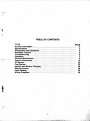
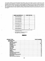
TABLE OF CONTENTS
TITLE
General lnlormatlon ..
Specilications
Dimensions and Clearances. ..
AssemblyTorques.....
Troubleshooting
-,ll /-\
:'
Periodic Maintenance.
Eleine Disassembly ..
PAGE
.. ...
.........'.
.
OilSystem...
Fuel System. .
lgnition and Battery Charging ..
Starting System
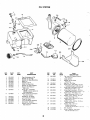
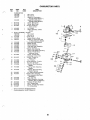
PartsCatalog .;...
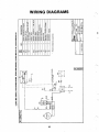
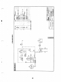
Wiring Diagrams ...:.
.....
.....
2
3
4
5
6
7
9
12
22
23
26
29
34
48
:l
t
.:!l
.:l:
tj
..::!
.J
,l{
;i
4
;tt:4
'i'.:.'1{
'
';"-' ..i6.
'.'",
i-;H
'9-#::,rS
,l:,..tff
.::
.i. .
':ii-n=ffi
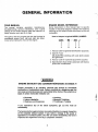
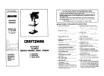
GENERAL INFORMATION
YOUR MANUAL
The manual contains operation, maintenance,
troubleshooting, service information, and a parts
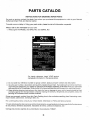
ENGINE MODEL REFERENCE
Some instructions in this manual refer to specific
models of industrial engines. ldentify the model by
catalog for the CCKA engine. Keep the manual in a
handy location and refer to it often.
referring to the model number as shown on the unit
nameplate.
Throughout the text, engine end with the flywheel is
considered engine front. Left and right are determined when facing the front of the engine.
How to lnlerpret a typical MODEL NUMBER
CCKA
MS
T
I
2
1
/
2813
J
TI
34
1. Factory code for general identification purposes.
2. Specific Type:
MS-ELECTRIC starting with stub shaft, starter
and generator.
3. Factory code for optional equipment supplied.
4, Specification (Spec letter) advances with factory
production mod if ication.
.\
i-wARNrNGl
U
ENGINE EXHAUST cAs (CARBON mbnOxroel IS DEADLY!
Carbon monoxlde lr an odorless, colorless gat lormed by lncomplete
combuslion ol hydrocarbon luels. Carbon monoxlde ls a dangerous gas that
can cause unconsciourne3s and ls potenllally lethal. Some ol the symptoms or
signs ol carbon monorlde inhalatlon are:
o Dizzlness
o lntense Headache
o Weakness and Sleepiness
ll you erperlence any ol the above
*
o Vomlllng
o Muecular Twllchlng
o Throbblng ln Temples
symptoms, gel
oul lnlo lresh
fi
G
air
immediately.
The best prolection against carbon monorlde inhalatlon is a regular lnspeclion
ol lhe complete erhaust system. ll you notlce a change ln the gound or
appearance ol erhaust system, shul the unlt down lmmedlalely and have it
inspected and repaired at once by a compelenl mechanic.
SPECIFICATIONS
All clearances glven at room temperature ol 70'F (21o C)
All dlmensions in inches unless othenylse specllled (metrlc equlvalents in parentheges where applicable).
Type.
Fuel .
Rated Power @ 3600 r/m...
No. of Cylinders..
Displacement....
Stroke
Bore .
Compression (sea level).
Crankshaft
Valve Lifters. . ...
Bearings (main and rod)
Oil Capacity including 1/2qt. (0.471) forfilter.
Lubrication System
lgnition
Cooling Air Volume at 3600 rpm..
Governor Type .
Fuel Pump Type.
Fuel Pump Lift ..
I
..
4 cycle, Air Cooled
Gasoline
16.5 HP (12.3 kw)
...... ........
2
49.8 in.3 (816 cmo)
3.000 inches (76.2 mm)
3.250 inches (82.6 mm)
100-120 psi (7.03-8.44 kg/sq cm)
Horizontal, Ductile lron
. ... Mechanical
Sleeve
. 2-1/2 U.S. Quarts (3.31 litres)
Full Pressure
Battery
..830 cfm (23.5 m3/min.)
Adjustable, mechanical flyball
Diaphragm
4 feet (1.22m\
Tune-Up Speclllcatlons
Breaker Point Gap (full separation)
Spark Plug Gap
lgnition T.iming
Carburetor Float Clearance (between float bowl gasket
and float)
I}
a
ie
&
0.020 (0.508 mm)
0.025 (0.635 mm)
19" BTC
5/16 (7.9 mm)
. All clearances glven at room temperalure ol 70" F (21'C)
All dlmensions ln lnches unless othemlse specified (metdc equivalents in parentheses where applicable).
Minlmum
lllaxlmum
0.006 (0.152 mm)
0.015 (0.381 mm)
0.008 (0.203 mm)
Q.017 (0.432
0.0010 (0.025 mm)
0.0025 (0.064 mm)
0.0025 (0.064 mm)
0.0040 (0.102 mm)
f;
Tappets
lntake
Exhaust
Valve Stem in Guide
lntake
Exhaust
Valve Seat lnterference Width
Valve Face Angle
Valve Seat Angle
Valve lnterference Angle
Crankshaft Main Bearing ....
......
Crankshaft End Play
Camshaft Bearing
Camshaft End Play
Rod Bearing ....
Connecting Rod End Play .
Timing Gear Backlash
Oil Pump Gear Backlash
Piston to Cylinder, Conformatic Type (measured below
oil-controlling ring
- 90o from pin) Clearance
Piston Pin in Piston
Piston Pin in Rod .
Piston Ring Gap in Cylinder
Crankshaft Main Bearing Journal
Standard Size
- Standard
Crankshaft Rod Bearing Journal
- Honed Size .... ..
Cylinder Bore
Standard Size
-
mm)
'l/32 (O.792 mml
3/64 (1.189 mm)
44"
450
10
0.002s (0.064 mm)
0.006 (0.152 mm)
0.0015 (0.038 mm)
0.003 (0.076 mm)
0.0005 (0.013 mm)
0.002 (0.051 mm)
0.002 (0.051 mm)
0.002 (0.051 mm)
0.0038 (0.096 mm)
0.012 (0.305 mm)
0.0030 (0.076 mm)
mm)
0.0023 (0.058
0.016 (0.406 mm)
0.003 (0.076 mm)
0,005 (0.127 mm)
mm) 0.0045 (0.1143 mm)
Thumb Push Fit
0,0002 (0.005 mm) 0.0007 (0.018 mm)
0,010 (0.254 mm) 0.023 (0.584 mm)
1.9992 (5.0779 mm) 2.0000 (5.0800 mm)
'
mm)
mm)
1.6252 (4.1280
3.249 (8.252
1.6260 (4.1300 mm)
3.250 (8.2550 mm)
ci
Tune-Up Specilications
Spark Plug Gap
lgnition Timing
Carburetor Float Clearance (between float bowl gasket
and float)
-\
0.0025 (0.0635
-
Breaker Point Gap (full separation)
(
0.020 (0.508 mm)
0.025 (0.635 mm)
19" BTC
5/16 (7.9 mm)
*
s
ASSEMBLY TORQUES
TOROUES
t
Assembly torques as given here require the use of a
torgue wrench. These assembly torques will assure
proper tightness without danger of stripping the
threads. lf a torque wrench is not available, you will
have to esti mate th e deg ree of tightness necessary for
the stud, nut or screw being installed and tighten
accordingly. Be careful not to strip the threads. Check
all studs, nuts and screws often with the engine cold.
Tighten as needed to prevent them from working
loose.
&
TORQUE SPECIFICATIONS
Connecting Rod Bolt
Oil Pump
Oil Base Mounting Screws
Rear Bearing Plate
Gear Case Cover
Starter Mounting Bracket to
Oil Base Screws
Other 5/16" Cylinder Block
Nuts
Flywheel Capscrew
Cylinder Head Nuts
Valve Cover Capscrews ..
Manifold
Fuel Pump Mounting Screws
Carburetor Mounting Stud
Nuts
Fr.-Lb.
kg/m
27-29
10-13
3.73-4.01
0.97-1.24
5.95-6.64
2.77-3.46
1.38-1.80
43-48
5.95-6.64
10-12
35-40
1.38-1.66
4.84-5.53
29-31
4.O1-4.29
+8
0.55-1.11
2.07-2.77
0.69-0.83
7-9
43-48
20-25
15-20
5-6
8-12
1
.1
1-1.66
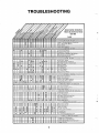
TROUBLESHOOTING
!*
6
3
o
OPERATION
BEFORE STARTING
Crankcase Oil
W-lnff
:l
ilC
-]
Do NOT check oal whlle the generatlng set is
operating. Hot
oil could cause bums by
blowing oul ol oll llll tube due to crankca3e pressure.
Be sure the crankcase has been filled with oil to the
€
full mark on the oil level indicator. Refer to the
PERIODIC MAINTENANCE section for the
STOPPING
Recommended Fuel
The engine will perform most satisfactory on non-
HIGH OPERATING TEMPERATURE
CONDITIONS
recommended oil changes and complete lubricating
oil recommendations.
leaded or regular-grade gasoline. However, nonlead-
ed gasoline is better for the engine. lf a situation
arises when you must use the tractor and these fuels
are not available, premium or highly-leaded gasoline
will work in the engine.
Before switching to a nonleaded gasoline f rom leaded
gasoline, take this precaution. Remove the cylinder
heads and remove all the lead deposits from the
engine.
It lead deposits are not removed lrom the
englne belore swilching lrom leaded to nonleaded gasoline, preignitlon can occur and cause englne damage.
STARTING
Refer to tractor manual for location, setting and
operation of electric start, choke and throttle controls.
APPLYING LOAD
lf practical, allow the engine to warm up
before
applying heavy loads.
Continuous overloading can cause englne
heating and eventual engine damage.
Break-ln Procedure
{l
Controlled break-in with the proper oil and a conscientiously applied maintenance program will help
to assure satisfactory service. While the engine can be
loaded to the full nameplate horsepower rating during
initial operation, apply half load the f irst few hours of
operation with intermittent periods of full load.
During break-in, check oil level often. Add oil if the
level is at low on the dipstick. Never overfill. This may
cause oil to foam and enter the breather system.
Drain the initial oil fill after five hours of operation
while the engine is still hot. See the PERIODIC
MAINTENANCE section for oil recommendations.
Refer to tractor manual for location and operation of
"Stop" control.
'1. See that nothing obstructs airf low to and f rom the
engine.
2. Keep cooling fins clean. Air housing should
properly installed and undamaged.
3, Keep ignition timing properly adjusted.
be
LOW OPERATING TEMPERATURE
CONDITIONS
1. Use correct SAE oil for temperature conditions.
Change oil only when engine is warm. lf an
unexpected temperature
drop causes an
emergency, move the tractor to a warm location.
2. Use fresh gasoline. Protect against moisture
condensation. Below 0'F (-18oC), adjust carburetor main jet for a slightly richer fuel mixture.
3. Keep ignition system clean, properly adjusted
and batteries in a well charged condition.
4. Partially restrictcool airflow, butusecareto avoid
overheating.
EXTREMELY DUSTY
CONDITIONS
AND
DIRTY
1. Keep unit clean. Keep cooling surfaces clean.
2, Service air cleaner as frequently as necessary.
3. Change crankcase oil every 20 operating hours.
4. Keep oil and gasoline in dust-tight containers.
5. Keep governor linkage clean.
HIGH ALTITUDE OPERATION
For operation at altitudes of 2500 feet (762 meters)
above sea level, close carburetor main jet adjustment
slightly to maintain proper air-to-fuel ratio (refer to
the "FuelSystem" section). Maximum power will be
reduced approximately four percent for each 1000
feet (305 meters) above sea level after the first 1000
feet (305 meters).
i
:
t
E
iI
.
'
I
,
ri
:
ouT-oF-sERvlcE
PRoTECTIOilI
Protect an engine which is to be outd:gervba
more than 30 days as lollows:
1. Run engine until thoroushly warm.
z. rurn off tuet suppty and run unrit the
for
5. Service air cleaner.
6. Flug exhaust outlet
I
7.
ensine
stops.
.
to
prevent entrance of
rnoibture, dirt, bugs, etc.
Provide a suitable cover for the entire
unit.
;; ;;;;;r;;;;;;;i"r,.r","r
'--\
f?rilF%LTl3t;ffinrtandfollowstandard
3. Drain oil from
rom oil base while stillwarm, Relill and
attach a warning tag. stating oil viscosity used.
4. Remove each spark plug. Pour 1 ounce (iwo
tablespoons) of rust lnhibitoroil{orSAE number
50 oil)'into eich cylinder. Crank enginestowly'(by
handj several times. lnstall spark Ft"g".
C
G
t
t
PERIODIC MAINTENANCE
PERIODIC MAINTENANCE SCHEDULE
Regularly scheduled maintenance is the key to lower
operating cosis and longer service life for the unit.
Use the following schedule as a guide. However,
actual operating conditions under which a unit is run
should be the determining factor in establishing a
maintenance schedule. When operating in very dusty
or dirty conditions, reduce some service periods.
Check the condition of the crankcase oil, the filters,
etc. frequently until ihe proper service time periods
can be established.
For any abnormalities in operation, unusual noises
rom engine or accessories, loss of power,
overheating, etc., contact your Onan dealer.
f
AFTER INDICATED OPERATING HOURS
SERVICE THESE ITEMS
lnspect Enqine Generally
Check Oil Level
Clean Governor Linkaqe
Service Air Cleaner
Chanoe Crankcase Oil
Replace Oil Filter
Replace Soark Pluqs
Clean Breather Valve
Check Breaker Points
Check Batterv Electrolyte Level
Clean Fuel Svstem
Replace Air Cleaner Element
Remove Carbon & Lead Deposits
Check Valve Clearance
I
40
80
100
200
400
X
x
x1
x1
x1
X
X
X
X
X
X
x1
X
X
- Perform more often in extremely dusty conditions.
NOTE: lf tractor is out of service for more than 30 days (between seasons,
for example), see "Out-of-Service Proteotion" in the OPERATION section.
x1
All exhaust system connections MusT be checked regularly for any
leaks and tightened as necessary. Do Nor terminate exhaust pipe
under tractor.
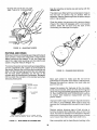
CRANKCASE OIL
When changing oil, fill the crankcase to the FULL
mark (Figure 1) with an SE (American Petroleum
lnstitute designation) oil of the viscosity specif ied on
the nameplate. lf SE oil is not available, SD or SD/CC
oil may be used.
Oil consumption may be higher with a multigrade oil
than with a single grade oil if both oils have comparable viscosities at210" F (99'C).Therefore, single
grade oils are generally more desirable, unless anticipating a wide range of temperatures. Use the
proper grade oil for the expected conditions.
Check oil level every 8 operating hours. Change oil
every 40 operating hours under normal operating
conditions. When operating in extremely dusty or
dirty conditions, change oil every 20 operating hours.
CAP AND OIL
LEVEL INDICATOR
WASHER
KEEP OIL
AT THIS LEVEL
NEVER OPERATE
ENGINE WITH OIL
BELOW THIS
LEVEL
--.-..I
LOW
ALWAYS REPLACE
CAP TIGHTLY, OR
OIL LEAKAGE MAY
occuR.
FIGURE 1. OlL LEVEL INDICATOR
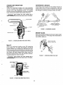
Change the crankcase oil filter every otheroil change
(80 operating hours), Remove the filter by turning
counterclockwise, using a filter wrench. Add the air
seal over the filter to prevent air loss around the
housing (Figure 2). Coat rubber gasket on filter with
f ilm of oil before installing. lnstallthe filterfingertight
plus 1/4 lo 1/2 turn. lf oil becomes so dirty that the
ELEMENT
markings on the oil level indicator cannot be seen,
change the filter and shorten the filter service period.
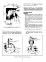
FIGURE 3.
FILTER
A!R, CLEANER ASSEMBLY
Extremely dusty conditions may require a change
every 50 operating hours. lnspect the filter mole
f requently if the engine appears to be losing poweror
idles roughly.
To service the air filter, remove the wing nut and
AIR SEAL
washer at the top. lf the f ilter element is dirty, clean by
tapping gently on a flat surface. When cleaning, do
not dent the sealing surfaces.
FIGURE 2. OIL FILTER AND AIR SEAL
Clean the sealing surfaces, pan and cover before
reassembly. Check to see that the pan is assembled
firmly onto the carburetor air intake. The,,O" ring in
the pan neck should make a tight seal around the air
i_ntlke. Tighten the clamp on the air intake. See Figure
3. Reassemble the air filter and replace the washer
and wing nut; tighten the wing nut finger-tight only.
AIR FILTER
The CCKA engine is equipped with apapercartridge,
automotive type air filter (Figure 3). Under normal
usage, change the filter every 200 operating hours.
t0
$
CRANKCASE BREATHER
GOVERNOR LINKAGE
Begin Spec J
Clean the crankcase breather cap, valve assembly
and the breather tube baffle in a petroleum-base
solvent every 200 operational hours. To remove
breather cap and valve assembly, remove the breather
hose clamp and breather tube clamp (Figure 4).
The linkage must be able to move freely through its
entire travel. Every 40 hours of operation, clean the
joints and lubricate as shown in Figure 6. Also inspect
the linkage for binding, excessive slack and wear.
Use extreme care when cleaning with
a
petroleum-base cleanser due lo lire hazard.
TO LOOSEN, PULL
JOINT APART, CLEAN
AND LUBRICATE WITH
KEEP 6OVERNOR
LINKAGE LUBRICATED
\^/ITH GRAPHITE
GRAPHITE
894 -r
FIGURE 6. GOVERNOR L]NKAGE
SPARK PLUGS
Each time the spark plugs are removed, inspect, clean
and regap (Figure 7). lf the plug looks discolored or
has fouled, replace it.
FIGURE 4. CRANKCASE BREATHER, BEGIN SPEC J
SPARK PLUG GAP
0.02s tN. (0.63s. MM
Spec G
Clean the crankcase breather every 200 operating
hours (Figure 5). To clean the breather, lift off the
rubber breather cap. Carefully pry thevalve from cap.
Otherwise press hard with both of yourthumbson top
of cap and fingers below to release valve from rubber
cap. Wash this fabric flapper type check valve in a
petroleum-base solvent. Dry and reinstall, positioning perforated disc toward engine.
l__W-anf
3..-.l
lr'C l
Use extreme care when cleaning with
AlTt
FIGURE
a
petroleum-base cleanser due lo lire hazard.
BREATHER TUBE
CAP
FLAPPER
VALVE
TUBE FROM
ASSEMSLY
AIR
CLE AN ER
FIGURE 5. CRANKCASE BREATHER, SPEC G
il
7.
CHECKING SPARK PLUG GAP
ENGINE DISASSEMBLY
3. Turn'the puller bar bolts in alternately, until the
lf engine disassembly is necessary, observe the
following order (i.e. flywheel, gear cover . . .). As
disassembly progresses, the order may be changed
as will be self-evident. The engine assembly
wheel snaps loose on the shaft.
)-v\aaa
l Donoluseascrewdriverorsimilartoolto
CAUTION I pry behind the llywheel against the gear
,-^:.tJ.r;-r
-{ case cover is dle-cast material and will
' cover, The gear
case
procedure is the reverse of disassembly. Any special
assembly instructions for a particular group are
included in the applicable section. When reassembling, check each section for these special assembly
instructions or procedures.
break ll too much pressure is applied in lhis manner.
4. Unscrew the puller from the flywheel, remove the
flywheel mounting screw and washer and pullthe
flywheel off the shaft. Take care not to drop the
wheel. Always use a steel key for mounting the
FLYWHEEL
flywheel.
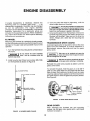
Removing the flywheel is a relatively simple process,
but the following procedure must be followed to avoid
damage to the gear case and possible injury to the
operator.
TRANSMISSION DRIVE GEARS
A standard gear puller is required to remove the drive
gears from the crankshaft. lf unusual resistance is
encountered, remove the puller and heat the gears
with a torch.
1. Turn the flywheel mounting screw outward about
two turns.
l-TARltrt{G I
,#.ih^air
to overheat and cause lhe
temper lo be drawn lrom lhe gears. Excessive
heat can damage the rear oil seal.
Take care not
Do not remove the screw completely
acls as a restrainer when lhe
llywheel snaps loose.
2. lnstall a puller bar (Onan tool number 420-0100)
WANNING
on the flywheel as shown in Figure 8.
Take care not to bum yoursell with the torch
or hol gears when removing or reinstalling.
Reinstall the puller and proceed as before until the
gears come loose.
To reinstall the gears, heat the gears in oil at 400'F
(205" C) and place them on the shaft with the shaft
keys in place, Set a collar on the shaft, such as a pipe
coupting; place a heavy washer over the end and turn
the shaft screw in until the gears are properly seated.
WHEEL PULLER
See Figure 9.
FIGURE 9. DRIVE GEAR INSTALLATION
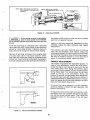
GEAR COVER
After removing the flywheel key and mounting
screws, tap. the gear cover gently with a soft-faced
hammer to loosen it.
FIGURE 8. BLOWER WHEEL PULLER
t2
GOVERNOR CUP
ERIloR ARM
ROLL PIN
RNOR SHAFT
ROTATE
GOVERNOR CUP
THAT ROLL PIN'
FITS INTO THE
SO
GOVERNOR
SHAFT YOKE
METAL LINED
(Smooth SidG
Towad Cup)
HOLE IN THE CUP
OIL SEAL
IF FEELER WILL
ENTER HOLE I/2 IN.
(l2.7MM) BALL HAs
FALLEN OUT
FIGURE 10. GEAR COVER ASSEiIBLY
When anstalling thegearcoyer, make sure that
the pin ln the gear coyer engages the governor cup correctly (see lollowlng).
3/4
WHEN GOVERNOR
19.05
IS PROPERLY
ASSEMBLEO THE
DIMENSION SHOWA
Turn the governor cup so thatthe metal lined hole is at
the three o'clock position. The smooth side of the
governor yoke must ride against the governor cup.
Turn the governor arm and shaft clockwise as far as
CAMSHAFT
GEAR
ON DRAWING \,VILL
BE AS INDICATEO
possible and hold in this position until the gear cover
is installed flush against the crankcase.
Be carelul not to damage the gear cover oil
seal. ll damaged, lt will have to be replaced.
CENTER PIN
Adjust the roll (stop) pin to protrude to a point 3/4
inch (19.05 mm) from the cover mounting surface.
See Figure 10.
SNAP RING
CAMSHAFT
OOVERNOR CUP
GOVERNOR CUP
With the gear cover removed, the governor can be
taken off after removing the snap ring from the
GOVERNOR FLYBALL
camshaft center pin. Catch the flyballs while sliding
the cup off. See Figure '11.
Replace any f lyball that is g rooved or has a f lat spot. lf
the arms of the ball spacer are worn or othenivise
damaged, replace the entire timing gear set. The
FIGURE 11. GOVERNOR CUP
governor cup must spin f reely on the camshaft center
pin without excessive loosenessorwobble. lf the race
surface of the cup is grooved or rough, replace it with
a new one.
the cup against the flyballs when measuring. lf the
distance is less (the engine may race, especially at no
load), remove the center pin and press a new pin in
only the required amount. Otherwise, grind off the
hub of the cup as required. The camshaft center pin
When installing the governor cup, tilt the engine so
the gear is up, put the flyballs in place and install the
cup and snap ring on the center pin (Figure 11).
cannot be pulled outward nor removed without
damage. lf the center pin extends out too far, the cup
will not hold the flyballs properly.
The camshaft center pin extends oul3/4 inch (19.05
mm) from the end of the camshaft. This distance
provides an in and out travel distance ol7/32 inch
(7.55 mm) for the governor cup, as illustrated. Hold
TIMING GEARS
lf replacement of either the crankshaft gear or the
camshaft gear becomes necessary, install both gears
r3
edge. The gear teeth must mesh so that these marks
coincide exactly when the gears are installed in the
engine (Figure 12). Be sure, when installing the
CRANKSHAFT
camshaft gear and shaft assembly, that the thrust
washer is properly in place behind the camshaft gear.
Replace the camshaft retaining washer and lock ring
to the crankshaft.
CYLINDER HEADS
Tighten the cylinder head in the order designated per
Figure 13 to a torque of 5 foot-pounds (0.69 kg/m),
then 10 foot-pounds (1.38 kg/m), etc., until all are
torqued 29 to 31 foot-pounds (4.01 lo 4.29 kg/m).
ffi
L.?:
^1!,:
h
f,t
i,l
ti
i::::
:tt7
----:
THESE MARKS MUST
ALIGN IYHEN INSTALL.
--
ING TIMING GEARS.
llo.l
FIGURE
rh t9/\7
v.-
cYutaDrl
13.
NO.2 CYUI{Dtr
HEAD BOLT TIGHTENING SEOUENCE
FIGURE 12. TIMING GEAR REMOVAL AND INSTALLATION
VALVES
Properly seated valves are essential to good engine
performance. The cylinder head is removable for
valve servicing. Do not use a pry to loosen the cylinder
head. Rap sharply on the edge with a soft-faced
hammer, taking care not to break any cooling fins. A
conventional type valve spring lifter may be used
when removing the valve spring locks, which are of
the split type. Clean all carbon deposits from the
cylinder head, piston top, valves, guides, etc. lf a valve
face is burned or warped, or the stem worn, install a
new valve.
new, never one only. Use a gear pulling ring (Onan
tool number 420-0248) to remove the crankshaft gear.
Be sure to remove the snap ring first. See Figure 12.
The camshaft gear is pressed on and keyed to the
camshaft. Remove the camshaft and gear as an
assembly after first removing the crankshaft gear,
lock ring and washer. Before removing the camshaft
and gear assembly, remove the cylinder head and
valve assemblies. Remove the operating plunger for
the breaker points. Remove the fuel pump and
tappets.
Worn valve stem guides may be replaced from inside
the valve chamber. See Figure 14. A seal is provided
behind the intake valve guides only. The smaller
diameter of the tapered valve gu ides must face toward
the valve head.
Press the camshaft out of the gear by use of a hollow
tool or pipe which will fit overthe camshaft center pin.
t@
spacer is a press
3"'*;'"'f ?'i,,I "-:;:'il:'ifl
lil lo the camshafl
gear.
Tappets are also replaceable trom the yalve chamber, alter tirst
removing lhe Yalve assemblies.
"",ffil':;
The valve face angle is 44o. The valve seat angle is
When pressing a camshaft gear onto the camshaft, be
45'. This 1o interference angle results in a sharp
sure the gear is started straight and that the key is
properly in place. lnstall the governor cup assembly
before installing the camshaft and gear in the engine.
seating surface between the valve and the top of the
valve seat. The interference angle method of grinding
valves minimizes face deposits and lengthens valve
life (Figure 15).
Each timing gear is stamped with an 0 mark nearthe
l{
NOTE: USE A STANDARD AUTOMOTTVETYPE WRENCH TO ADJUST THE
TAPPETS.
NOTE: SEE-VALVE TAPPET
CLEARANCES IN TEXT.
H
! vetve
l7I
_#
VALVE SEAT
ffi
VALVE ADJUSTING
SCREW
RETATNER
VALVE SPRI
vALVE GUtDEilVi,i
vnlVe spnrNc
WASHER LOCK
A?!C
VALVE ROTATOR
FIGURE
14.
CCKA VALVE SYSTEM
the marks rub off uniformly when the valve is rotated
part of a turn against the seat.
Do not hand lap the valves, il al all avoidable,
since the sharp contact can be destroyed'
This is especially important where slellite laced valves and seats
are used.
Lightly oil the valve stems and reassemble all parts
removed. Adjust the valve clearance (see fappet
Adjustment).
Finish the valve faces in a machine lo 44". Grind the
valve seats with a 45o stone. Width of the seat band
should bel/32 to3/64 (O.792to 1.189mm)of an inch
wide. Grind only enough to assure proper seating.
The positive type valve rotocoils serve to prolong
valve life and decrease valve repairs. Check the
rotocoils periodically by removing the cylinderheads
and cranking the engine. When functioning properly,
the valve is rotated a fraction of a turn each time it
opens. lf rotocoils are faulty, install new ones.
Remove all grinding compound from engine parts
and place each valve in its proper location. Check
each valve for a tight seat, using an air pressure type
testing tool. lf such a tool is not available, make pencil
marks at intervals across the valve face and observe if
TAPPET ADJUSTMENT
The engine is equipped with adjustable tappets. To
make a valve adjustment, remove the valve covers.
Crank the engine over slowly by hand until the left
hand intake valve, when facing the flywheel, opens
and closes. Continue about 1/4turn until the correct
timing marks align. This should place the left hand
piston at the top of its compression stroke, the
position it must be in to get proper valve adjustment
for the left hand cylinder. Clearances are shown in
D I M E NS I ONS AND C LEARA N CES section. For each
valve, the gauge should just pass between the valve
stem and valve tappet (Figure 16).
To correct the valve clearance, turn the adjusting
screw as needed to obtain the right clearance. The
screw is self-locking.
To adjust the valves on the right hand cylinder, crank
the engine over one complete revolution and again
line up the correct timing marks. Then follow the
adjustment given for the valves of the left hand
cylinder.
FIGURE
15.
VALVE FACE AND SEAT ANGLES
r5
INTAKE AND EXHAUST VALVES
(SEE TABLE OF CLEARANCES)
Keep the connecling rod bearing caps and bearings with their
respeclive rods.
The pistons are f itted with two compression rings on
top and one oil control ring on bottom with
an
expander. Remove these rings f rom the piston using a
piston ring spreader.
Clean the piston ring grooves with a groove cleaner
(Figure 18). Clean all passages with a non-caustic
solvent. Clean the rod bore and the back of the
connecting rod bearings thoroughly.
FIGURE
16, ADJUSTING
TAPPETS
PISTONS AND RINGS
Whenever there is a noticeable wear ridge at the top of
each cylinder, remove the ridge with a ridge reamer
before removing the pistons. lf not, the rings can
catch the ridge when pushing out the pistons and
cause a ring land fracture (Figure 17).
To remove the piston and connecting rod assemblies,
turn the crankshaft until a piston is at the bottom of
the stroke. Remove the nuts f rom the connecting rod
bolts. Lift the rod bearing cap from the rod, and push
the rod and piston assembly out the top of the
cylinder with the handle end of a hammer. Be careful
not to scratch the crankpin or the cylinder wall when
removing these parts.
FIGURE
18.
Mark each piston
CLEANING RING GROOVES
to
make sure the rod will be
assembled on the piston from which it was removed.
Remove the piston pin retainer from each side and
push the pin out.
WEAR RIDGE
RING LAND
lnspect the pistons for fractures at the ring lands,
skirts and pin bosses. Check for wear at the ring land
using new rings and a feelergauge as shown in Figure
19. See DIMENSIONS AND CLEARANCES section
for proper side clearance measurement and ring
groove widths.
PISTON
lmproper width rings or excessive ring side clearance
can result in ring breakage. New rings in worn ring
g rooves don't have good cyl inder wal I contact ( Figu re
20).
Replace pistons showing signs of bad scoring or
burring, excessive skirt clearance, wavy or worn ring
lands, f ractures or damage f rom detonation. Replace
piston pins showing f ractures, scored bores or bores
out of round more than 0.002 inch (0.051 mm).
PISTON WITH LARGE WE-AR
REMOVING PISTON
RIDGE COTJt.O
BREAK RING OR RING LAND
RIOGE
COIJI.O BREAK
FIGURE
17.
Use a new piston pin to check the pin bushing in the
WEAR RIDGE ON CYLINDER WALL
r6
-')
\ll
i
PISTON RING IN
CYLINDER BORE
9l
FEELER GAGE
FIGURE
19.
INSPECTING RING LANDS
FIGURE
connecting rod for wear. The clearance should be as
shown in D I M E N S IONS AND CLEARAN CES section.
21.
FITTING PISTON RINGS TO CYLINOER
should be fitted with an expander and an oil control
ring and the two upper grooves fitted with compression rings. lf a chrome faced ring is used, it will be in
the top groove, The oil control ring is selected for best
performance in regard to the correct unit pressure
characteristics.
Before installing new rings on the piston, check the
ring gap by placing each ring squarely in its cylinder
at a position corresponding to the bottom of its travel
(see Figure 21). The gap between the ends of the ring
is given in D/MENS/ONS AND CLEARANCES
section. Rings which are slightly oversize can be f iled
as necessary to obtain the correct gap, but do not use
rings which require too much filing. Standard size
rings can be used on 0.005 inch (0.127 mm) oversize
pistons. Other oversize rings must correspond with
the oversize pistons. Rings of the tapered type are
usually marked top on one side, or identif ied in some
other manner. lnstall the ring with this mark toward
the closed end of the piston.
The piston is fitted with a full-floating type piston pin.
The pin is kept in place by two lock rings in the piston,
one at each side. Be sure these lock rings are properly
in place before installing the piston and connecting
rod in the engine. Refer lo DIMENS/ONS AND
CLEARANCES section for the correct piston-tocylinder clearance.
CONNECTING RODS
Service the connecting rods at the same time the
pistons or rods are serviced. Remove the rods with the
pistons. Replaceable bushings and bearings are
used. See PARIS CATALOG section for available
undersize and standard size bearings.
Space each ring gap one third of the way around the
piston from the preceding one, with no gap directly in
line with the piston pin. The bottom piston ring groove
Proper clearance is obtained by replacing the pin
bushing and the bearings. The rod bearings are
precision size and require no reaming.
CYLINDER
\^/ALL
lnstall the connecting rods and caps with raised lines
(witness marks) aligned and with the caps facing
toward the oil base. The rod and cap numbered 2 fits
on the crankshaft journal nearest the bearing plate.
Coat the crankshaft journal bearing surfaces with oil
before installing the rods. Crank the engine by hand
to see that the rods are free. lf necessary, rap the
connecting rod cap screws sharply with a soft-faced
hammer to set the rod square on the journal.
PISTON
RING
IMPROPER
Checking
RING CONTAC
Bearing Clearance With
Plastigage
Make certain that all parts are marked or identif ied so
that they are reinstalled in their original positions.
FIGURE 20. NEW RING IN WORN PISTON RING GROOVE
l7
reinstall the bearing cap. Tighten the bolts to the
in the ASSEMBLY IORQUES
section. Do not turn the crankshaft.
torque specified
Remove the bearing cap. Leave the flattened
Plastigage on the part to which it has adhered and
compare the widest point with the graduations on the
Plastigage envelope to determine bearing clearance.
CYLINDER BLOCK
lnspection
1. Make a thorough check for cracks. Minute cracks
may be detected by coating the suspected area
with a mixture ol 25o/o kerosene and 750lo light
motor oil. Wipe the part dry and immediately
apply a coating of zinc oxide (white lead) dissolved in wood alcohol. lf cracks are present, the
white coating will become discolored at the
defective area.
2. lnspect the cylinder bore for scoring. Check the
Welsh plugs for a tight, even fit and the fins for
breakage.
3. Check the cylinder bore for taper, out of round
and wear with a cylinder bore gauge, telescope
gauge or inside micrometer (Figure 23). These
measurements should be taken at four places
the top and bottom of piston ring travel.
4. Record measurements taken lengthwise at'the
top and bottom of the piston travel as follows:
a. Lengthwise of the block, measure and record
FIGURE 22. MEASURING BEARING CLEARANCE WITH
PLASTIGAGE
Place
a piece of correct size Plastigage in
the
bearing cap the full width of the bearing insert about
1/4 inch (6.35 mm) off center (Figure 22). Rotate the
crank about 30o from bottom dead center and
FIGURE
23.
as "A" the diameter of the cylinder at thetop of
the cylinder where the greatest ring
occu rs.
METHODS OF CYLINDER INSPECTION
r8
wear
4.
5.
rot
p
6.
7.
FIGURE
24.
HONING CYLINDER
b. Also, lengthwise of the block, measure and
record as "B" the cylinder diameter at the
piston skirt travel.
c. Crosswise of the block, measure and record as
"C" the diameter of the top of the cylinder at
the greatest point of wear.
8.
d. Measure
and record as "D" the diameter at the
bottom of the cylinder bore and crosswise of
the block.
e. Reading "A" compared to "B" and reading "C"
compared to reading "D" indicates cylinder
stones come in contact with the cylinder wall at
the narrowest point.
Turn the hone by hand. Loosen the adjusting nut
until the hone can be turned.
Connect drill to hone and start drill. Move the
hone up and down in the cylinder approximately
40 cycles per minute. Usually the bottom of the
cylinder must be worked out first because it is
smaller. Then when the cylinder takes a uniform
diameter, move the hone up and down alltheway
through the bore. Follow the hone manufacturer's
recommendations for wet or dry honing and
oiling the hone.
Check the diameter of the cylinder regularly
during honing. A dial bore gauge is the easiest
method but a telescoping gauge can be used.
Check the size at six places in the bore; measure
twiceatthetop, middle and bottom at90o angles.
When the cylinder is approximately 0.002 inch
(0.051 mm) within thedesired bore, change to fine
stones and finish the bore. The finish should not
be smooth but as shown in Figure 25. The
crosshatch formed by the scratching of the
stones should form an angle of 23". This can be
achieved by moving the hone up and down in the
cylinder about 40 cycles per minute.
Clean the cylinder block thoroughly with soap,
waterand clean rags. A clean white rag should not
be soiled on the wall after cleaning is complete.
Do not use a solvent or gasoline since they wash
the oil f rom the walls but leave the metal particles.
9.
Dry the crankcase and coat it with oil.
taper.
f. lf cylinder taper exceeds 0.005 inch
(0.127
mm), rebore and hone to accommodate the
next oversize piston. Reading "A" compared to
reading "C" and reading "B" compared to
reading "D" indicates whether or not the
cylinder is out of round. lf the out of round
exceeds 0.002 inch (0.051 mm), the cylinders
must be rebored and honed for the next
oversize piston. A reboring machine is used
when going to oversize pistons. The following
repair data covers honing to oversize by useof
a hone.
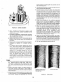
Repair
1. A hone can be used to rebore a cylinder (Figure
24). Remove stock to 0.002 inch (0.051 mm),
undersize of finish bore with coarse hone (100
grit), then complete honing with finish hones (300
grit).
2. Anchor the block solidly for either vertical or
horizontal honing. Use either a drill press or
heavy-duty drill which operates at approximately
250 to 450 rpm.
3. Lower the hone into the cylinder until it protrudes
1/2 to 3/4 inch (12.7 to 19.0 mm) past the end of
the cylinder. Rotate the adjusting nut until the
PRODUCE CROSS HATCH
AVOID THIS FINISH
SCRATCHES FOR FAST
RING SEATING
FIGURE 25.
l9
HONE FINISH
CRANKSHAFT
PRECISION TYPE .OO NOT LINE REAM OR EORE.
lnspect the bearing journals. lf they are scored and
cannot be smoothed out by dressing down, the
bearing journals should be refinished to use nearest
available undersize bearings or a new crankshaft
should be installed. lf a worn main bearing journal
cannot be fitted with an available precision type
undersize bearing, then refinish it to the next undersize. I f a worn rod journal cannot be f itted by installing
new bearing inserts, then refinish it to take the
corresponding undersize bearing insert available.
| 7,/32 tN
(9.55 mor)
ALI6N HOLE IN BEARING
FROM
WITH HOLE
OUTS
ID E
IN BEARING BORE
CAUS}IAFT IEARINO
Whenever making major repairs on the engine,
always inspect the drilled passages of the crankshaft.
Clean them to remove any foreign nlaterial and to
assure proper lubrication of the connecting rods.
BEARINGS
I
Removal of the camshaft or crankshaft bearings
requires complete disassembly of the engine. Use a
press or a suitable drive plug to remove the bearings.
Support the casting to avoid distortion and avoid
damaging the bearing bore during removal and
installation. Use oil on the bearings to reduce f riction
when installing and again lubricate with oil after
installing (see Figure 26). Use Onan combination
bearing driver 420-0324 lo install the camshaft
bearings.
I
0
PRECISION TYPE.
OO NOY LINE REAM OR EORE.
CRANXSHAFT EEARINO
Camshaft
FIGURE 26. INSTALLATION OF CAM AND CRANKSHAFT
Replacement camshaft bearings are precision type
which do not require line reaming or line boring after
installation. Coat the bearing with lubricating oil to
reduce friction. Place the bearing on the crankcase
over the bearing bore with the lubricating hole (front
only) in proper position. Be sure to start the bearing
straight. Press the front bearing in flush with the
outside end of the bearing bore. Press the rear
bearing in until past the ignition plunger hole.
BEARINGS
crankshaft is installed. The oil grooves in the thrust
washer bearings must face the crankshaft. Be sure
two notches fit over lock pins.
OIL SEALS
Crankshalt
The bearing plate must be removed to replace its oil
seal. Drive the oil seal out f rom the inside using Onan
bearing plate driver 420-0181 and gear cover driver
420{313.
New crankshaft main bearings are precision type
which do not require line reaming or line boring after
installation. See PARfS CATALOG section for standard size and undersizes available.
Before installing the seals, fill the space between
seals with a f ibrous grease or stiff cup grease. This will
improve sealing (see Figure 27).
Before putting in the main bearings, expand the
bearing bore by placing the casting in hot water or in
an oven heated to 200o F (93" C). lf practical, cool the
precision bearing to shrink it.
When installing the gear cover oil seal, tap the seal
inward until it is 1 inch (25.4 mm) from the mounting
face of the cover. lnstall new style, thin open face seal,
1 -7 / 64 i nches (28.2 mm) f rom mou n ti n g face of cove r.
For putting in either the front or rear main bearing,
using instructions following, always align the oil
hole(s) in the bearing with the oil hole(s) in the
bearing bore. The oil passage must be at least 1/2
open. The cold oiled precision bearing should require
only light taps to position it. lnstall the bearing flush
with the inside end of the bore. lf the head of a lock pin
is damaged, use side cutters or "Easy-Out" tool to
remove pin. Then install a new lock pin. Apply oil to
the thrust washers to hold in place when the
When installing the bearing plate oil seal, tap the seal
into the bearing plate bore to bottom against the
shoulder in the plate bore. Use a seal expander, or
place a piece of shim stock around the end of the
crankshaft, when replacing the bearing plate to avoid
damaging the seal. Remove the shim stock as soon as
the plate is in place.
20
Use heavy fibcr or
cup Srcasc in spacc
between seals to
REAR BEARING PLATE
THIS SURFACE SHOULD BE
CLEANED OF ALL OLD
SEALING COMPOUND BE.
FORE INSTALLING SEAL.
THIS SURFACE SHOULD BE
CLEANED OF ALL OLD
SEALING COMPOUND BE.
FORE INSTALLING SEAL.
GEAR COVER OIL SEAL
DRIVE OR PRESS OIL
SEAL TO SHOULDER
OF THE PLATE BORE
REAR BEARING PLATE
OIL SEAL
FIGURE
27.
GEAR COVER AND REAR BEARING PLATE OIL SEALS
replace the gasket with a thicker one. Reinstall the
end plate making sure the thrust washer notches line
up with the lock pins. Torque and recheck endplay of
the crankshaft.
CRANKSHAFT ENDPLAY
After the rear bearing end plate has been tightened
using the torque recommended in ASSEMBLY TORQUES section, check the crankshaft endplay as
shown in Figure 28. lf there is too much endplay (see
D/MENS/ONS AND CLEARANCES section for
minimum and maximum endplay), remove the rear
bearing endplate and replace the gasket with a
thinner gasket from the gasket kit. For too little
endplay, remove the rear bearing end plate and
l//t'
OIL PUMP
Check the oil pump thoroughly for worn parts. Oilthe
pump to prime
before reinstalling (Figure
SySfEM section fordescription of the oil
bypass relief valve and cleaning instruction if normal
oil pressure (30 psi or higher) is in doubt.
@
REAR BEARING
PLATE
OIL PUt'lP INTAI(E
TURNEOE
ON LEFT
UNSCREW
OIL
SIDE
*
CUP
--
PUI,IP
FRq{ IilTAKE CUP AT THIS POINT
To rcarqnblG rGvcr3! tha proccdure.
MEASURE ENOPLAY
HERE
2S.
is
available separately. lnstall a new pump assembly, if
required.
CRANKCASE
FIGURE
29).
are not available individually. The suction cup
See the O/L
L
it
Except for gaskets, the component parts of the pump
FIGURE
MEASURING CRANKSHAFTENDPLAY
2l
29.
OIL PUTIP
OIL SYSTEM
The CCKA engine has pressure lubrication to all
working parts. The oil system includes:
Oil intake cup
Gear type oil pump
Oil pressure gauge
Oil passages to deliveroil throughout engine
Oil filter
The oil pump is located on the front surface of the
crankcase and is driven by the crank gear. The inlet
pipe and screen assembly is attached directly to the
pump body. A discharge passage in the cover of the
pump registers with a drilled passage in the
crankcase. Parallel passages distribute oil to the front
main bearing, rear main bearing and pressure control
bypass valve.
OIL BYPASS RELIEF VALVE
ADJUSTMENT
CW-INCREASE
CCv\/- DECREASE
FIGURE 30. BYPASS VALVE ADJUSTMENT
Circumferential grooves in the main bearings supply
oil to the connecting rod bearings through drilled
passages from each journal.
2. Remove spring and plunger with a magnet tool.
A drilled passage connects the front main bearing oil
Clean plunger and spring with a suitable solvent
and reinstall.
supply to the front camshaft bearing. The flyball
governor is lubricated by a drilled passage in the f ront
camshaft journal.
Bypass Valve Adjustment
This adjustment applies to all Spec G models except
the CCKA-MS/2116G and CCKA-MS/2567c modets.
To increase oil pressure, loosen the locknut and turn
the stud inward (Figure 30). To decrease oil pressure,
loosen the locknut and turn the stud outward. Be sure
to tighten the locknut securely after making an
adjustment. The spring and plunger can be removed
and cleaned.
The oil overflow from the bypass valve furnishes
lubrication to the camshaft drive gears.
OIL BYPASS VALVE
The bypass valve (located to the right and behind the
gear cover) controls oil pressure by allowing excess
oil to flow directly back to the crankcase. Normally
thevalve beginsto open about30psi (2.11 kg/sq cm).
Low oil pressure may indicate worn main or connecrod bearings, i mp roper clearance at th ese poi nts,
ti n g
The valve is nonadjuslable tor all models begin Spec J and models
CCKA-MS/2I11G and CCKA-MS/2567G. Other Spec G models
had an adjustable bypass valve (see "Bypass Valve Adjuslment").
a weak or broken bypass spring, an improperly
adjusted bypass or a defective gauge. Check the oil
pressure gauge before making any other test; it may
be defective.
Normally the valve requires no maintenance. To
determine if abnormal (high or low) oil pressure is
caused by a sticky plunger, inspect as follows.
1. Remove capscrew or slotted stud and locknut
located behind gear cover and under governor
arm. Location of the capscrew is the same as
shown for the slotted stud and locknut in Figure
LOW OIL PRESSURE SWITCH
All models except the CCKA-MS/1831G have a tow oit
pressure switch. lt is generally used to operate a low
oil pressure warning light foroil pressure lowerthan 8
to 10 pounds per square inch (0.56 to 0.70 kg/sq cm).
30.
22
FUEL SYSTEM
3. Remove load from the engine.
4. Turn idle adjustment screw counterclockwise
until engine speed drops slightly. Then turn the
screw clockwise until speed returns to normal.
GENERAL
Satisfactory engine performance is largely dependent upon correct fuel system adjustments. However,
adjustments cannot fully compensate for low engine
power due to wear, etc. lf trouble develops, follow an
orderly procedure to determine the cause before
making any adjustment.
Alternate Method (No load adiustment possib/e/
1. Start the engine and allow it to warm up.
2. Push in on the governor mechanism to slow tlrre
unit down to about 400 to 500 rpm.
3. Release the governor mechanism to allow the
engine to accelerate. lf the engine accelerates
evenly and without a lag, the load screw setting is
correct. lf not, adjust the screw counterclockwise
about 1/4lurn and again slow down the engine
and release the mechanism. Continue until the
engine accelerates evenly and without a time lag
after releasing the governor.
4. Push in on the governor mechanism to slow the
unit to 400 to 500 rpm. Set the idle screw for even
operation so the engine isfiring on both cylinders
and running smoothly.
Adjusting the carburetor is means of obtaining the
correct fuel-to-air mixture for smooth, efficient
operation. Always adjust in two steps, first the load
adjustment and then the idle adjustment.
CARBURETOR ADJUSTMENTS
Before adjusting the carburetor, be sure the ignition
system is working properly and the governor is
adjusted. Allow the engine to warm before starting
carbu retor adjustments.
It carburetor is completely oul ol adjustment so the engine will not
start, open both adjuslmenl screws counterclockwise 1 to 1-1l2
turns oll thelr seats to permit starting. Do nol lorce the needles
againsl lheir seats. This can bend the needle.
CARBURETOR DISASSEMBLY
1. Apply a full load to engine (if possible).
2. Turn the load adjustment screw clockwise
(Figure 31) until engine speed drops. Then turn
screw counterclockwise until engine speed
returns to normal.
1. Remove the choke linkage from the choke cable
bracket and clip.
2.
Remove the main carbu retor body f ronn the choke
sleeve.
3. Remove the float pin and float. See Figure 32.
4. Lift out the fuel inlet valve and unscrew the valve
LOAD ADJUSTMENT
WRENCH
seat.
5. Remove the load and idle adjustment screws.
6. Remove the throttle plate screws and the plate
and pull out the throttle shaft.
7. Remove the choke plate screws and plate and pull
out the choke shaft.
Cleaning and Repair
To clean the carburetor, soak all components
thoroughly in a carburetor cleaner following the
cleaner manufacturer's instructions. Be sure all carbon is cleaned f rom the carburetor bore, especially in
the area of the throttle valve. Blow out the passages
with compressgd air. lf possible, avoid using wire to
clean out the passages. The float should fit freely on
its pin without binding. I nvert the carbu retor body and
measure the float level.
IDLE
ADJUSTMENT SCREW
LOAD
ADIUSTMENT SCREW
FIGURE
31.
CARBURETOR ASSEMBLY
1. lnstall the throttle shaft and plate, using
new
screws and lockwashers. lnstall the bevel mated
CARBURETOR ADJUSTTTIENTS
23
FLoAr
PrNA
MEASURE WITh
DRILL BIT
SLEEVE
FUEL INLET
VALVE SEAT
BOOY TO BOIVL
GASKET
THIS
DIMENSION
SHOULD BE
5/.16 lN (7.9 mm)
FUEL INLET
VALVE
FIGURE
FIGURE
32,
33.
FLOAT LEVEL SETTING
tank. lf the line isopen and no fuel comesthrough, the
pump is defective, Failure of the pump is usually due
to a leaking diaphragm valve or valve gasket, a weak
or broken spring, or wear in the drive linkage. Oil
diluted with gasoline may indicate a faulty
diaphragm. lf the operator chooses to repair the
pump rather than install a new one, the use of a
complete repair kit is recommended.
CARBURETOR DISASSEMBLY
Fuel Pump Reconditioning
to the carburetor body. On plates marked with the
letter C, install with the mark on the side toward
the idle port when viewed from the flange end of
1. Remove fuel lines and mounting screws holding
pump to engine. See Figure 34.
2. Make an indicating mark with a file across a point
at the union of the fuel pump bolt and cover. This
mark will assure proper reassembly. Remove
assembly screws and remove upper pump body.
3. Turn pump body over and remove valve plate
the carburetor. To center the plate, back off the
top screw, close the throttle lever and seat the
plate by tapping it with a smallscrewdriver. Then
tighten the two screws.
2. lnstall the choke shaft and plate. Center the plate
in the same manner as the throttle plate (Step 1).
Use new screws and lockwashers.
3. lnstall the fuel inlet valve seat and valve.
4. lnstall the float and float pin. Centerthepin sothe
float bowl does not ride against it,
5. Check the float level with the carburetor casting
inverted. See Figure 33.
6. lnstall the carburetor body with the gasket aligned properly.
7. lnstall the fuel ad.iustment screws finger tight.
Then back out 1 to 1-'l12 turns.
8. Reconnect the choke linkage.
screw and washer. Remove valve retainer, valves,
valve springs and valve gasket, noting their
position. Discard valve springs, valves and valve
retainer gasket.
4. Clean pump body thoroughly with solvent and a
fine wire brush.
5. Holding the pump cover with the diaphragm
surface up, place the new valve gasket into the
cavity. Assemble the valve spring and valves in the
cavity. Reassemble the valve retainer. Lock in
position by inserting and tightening fuel pump
valve retainer screw.
6. Place pump body assembly in a clean place and
rebuild the lower diaphragm section.
7. Holding mounting bracket, press down on the
diaphragm to compress spring under it, then turn
bracket 90 degrees to unhook diaphragm so it can
be removed.
8. Clean mounting bracket with a solvent and a fine
wire brush.
FUEL PUMP
A diaphragm type fuel pump is used. lf fuel does not
reach the carburetor, check the fuel pump.To do this,
disconnect the fuel line at the carburetor and, while
cranking the engine slowly by hand, observe whether
f uel comes through the line. Be sure there is fuel in the
21
UPPER PUMP BOOY
(NOT SERVICEABLE)
o
CARBURETOR
THROTTLE PLATE
.VALVE.GASKET-OO
TVALVE AND CAGE
GOVERNOR CONTROL
VE CAGE
RETAINER
'DIAPHRAGM ASSEMBLY
IFUEL
PUMP
ROO SPRING
TMOUNTING GASKET
6OVERNOR ARM
AND SHAFT
- LINKAGE BRACKET
GOVERNOFI CUP
GOVERNOR SHAFT YOKE
BOOY
I.
FIGURE
35.
GOVERNOR LINKAGE
PARTS INCLUDED IN REPAIR KIT.
FIGURE
34.
dash panel until the desired speed is reached.
FUEL PUMP ASSEMBLY
The design of the variable speed governor gives an
automatic decrease in sensitivity when the speed is
increased and the result is good stability at all speeds.
9. Replace the diaphragm fuel pump rod spring,
diaphragm gasket, stand new spring in casting,
position diaphragm, compress spring and turn 90
degrees to reconnect diaphragm.
10. Hold bracket, then place the pump cover on it
(make sure that indicating marks are in line) and
insert the four screws. DO NOT f/GHfEN. With
the hand on the mounting bracketonly, push the
pump lever to the limit of its travel and hold in this
position while tightening the four screws.
Before making governor adjustment, run the engine
about 15 minutes to reach normal operating
temperature. lf the engine is being run with the
throttle wide open, either the governor is not properly
adjusted or the engine is overloaded. After long
usage, it is difficult to determine if thegovernorspring
has become fatigued. Replace the spring if governor
regulation is still erratic after making proper adjustments. See Figure 35.
This is importanl to preyent stretching
the cliaphragm.
A reliable instrument for checking engine speed is
required for accurate'governor adjustment. Engine
11. Mount the fuel pump on engine, using new
mounting gaskets. Connect the fuel lines.
speed can be checked with a tachometer.
GOVERNOR ADJUSTMENT
Check the governor arm, linkage, throttle shaft, and
lever for binding condition or excessive slack and
wear at connecting points. A binding condition at any
point will cause the governor to act slowly and
regulation will be poor. Excessive looseness will
cause a hunting condition and regulation will be
erratic. Work the arm back and forth severaltimes by
Engine speed is governor-controlled and preset at the
factory. Proper governor adjustment is one of the
most important factors in maintaining the powerand
speed desired from the engine.
These engines are adapted for use where a wide
range of speed settings is desired. Engine speed is
controlled at any given point between minimum and
maximum by simply shifting the throttle lever on the
hand while the engine is idle.
lf
either of these
conditions exists, find out where the trouble lies and
adjust or replace parts as needed.
25
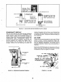
IGNITION AND BATTERY CHARGING
IGNITION TIMING
Engine Running
lgnition Timing
IGNITION SYSTEM
The engine is equipped with an automotive type
battery ignition system. Both spark plugs f ire
simultaneously, thus the need for a distributor is
-
Always check timing after replacing ignition points or
if noticing poor engine performance. Proceed as
follows:
1. To accurately check the ignition timing, use a
timing light when engine is running. Connect the
timing light according to its manufacturer's instructions. Either spark plug can be used as they
fire simultaneously.
2. Place a white chalk or paint mark on the timing
eliminated. Spark advance is fixed at 19'BTC (before
top center) which should be maintained for best
performance. lgnition timing should be checked
periodically, especially after breaker point replacement.
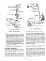
BREAKER POINTS
1. Remove the two screws and the cover on the
mark.
breaker box.
2. Remove the two spark plugs so bngine can be
easily rotated by hand. lf plugs have not been
changed within the last 100 hours, replace them
with new ones after setting the breaker points.
3. Remove the two mounting screws (A)and pullthe
points out of the box just far enough so screw (B)
can be removed. See Figure 36. Replace points
with a new set but do not completely tighten
mounting screws (A).
4. Rotate the engine clockwise (facing flywheel)by
hand until points are fully open. Turn screw (C)
until point gap measures 0.020 inch (0.508 mm)
with a flat thickness gauge.
5. Tighten mounting screws and recheck gap.
6. Proceed Io lgnition Timing.
3. Start the engine and check the timing (19' BTC).
4. lf timing needs adjustment, loosen the mounting
screws on breaker box and move it left to advance
or right to retard the timing.
5. Tighten the screws on the breaker box and
recheck timing.
6. Replace breaker box cover and any other
hardware removed.
lgnition Timing
ground on the engine.
2.
'
on lhe poinl's pivol point (Figure 36).
Turn crankshaft against rotation
(counterclockwise) until the points close. Then slowly
PLACE DROP OF OIL ON PIVOT POINT
WHENEVER NEW POINTS ARE
INSTALLED
FOR
Engine Not Running
con nected and tou ch the other test prod to a good
Each time new breaker points are inslalled, place a drop ol oil
REFERENCE MARK
-
1. Connect a continuity test lamp set across the
ignition breaker points. Touch one test prod to
the breaker box terminal to which the coil lead is
BOX-
RETARD
APPROXIMATE TIMIN6 TO ADVANCE OR ..+
FIGURE 36. IGNITION TIT,IING
2S
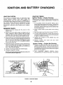
BATTERY CHARGING,
OHMMETER
FLYWHEEL
ALTERNATOR
The flywheel alternator is a permanent magnet alternator and uses a solid-state voltage reg u lato r-rectif ier
for controlling output (Figure 38).
A 30-ampere fuse is included in the battery charging
system to protect the alternator in case the battery
cables are accidently reversed. Replace the fuse with
Onan Fuse 321-0162, Buss AGC30 or equivalent.
Weak ignition spark or a discharged battery indicate
trouble in the charging system. But before testing the
engine's charging system, always check the battery
for serviceability.
FIGURE
37.
Keep these points in mind when testing or servicing
the flywheel alternator:
1. Be sure the output plug (connector) is inserted
properly. The plug must bottom in receptacle
eliminates any resistance due to a poor connection. Keep clean and tight.
2. Be sure regulator-rectifier output control has a
good ground connection. Mating surface for
mounting must be clean and fasteners tightened
properly.
3. Never reverse the battery leads.
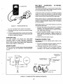
TESTING IGNITION COIL
turn the crankshaft with rotation (clockwise)
3. The lamp should go out just as the points break
(19'BTC).
4. lf timing needs adjustment, loosen the mounting
screws on breaker box and move it left to advance
or right to retard the timing.
IGNITION COIL
To check ignition coil (Figure 37), first
ohmmeter leads on small terminals.
place
Resistance
Regulator-Rectifier Tests
The lollowing tests lor the regulator-rectilier require a fully-
should read 1/2to 1-1/2 ohms. Next place ohmmeter
leads inside of spark plug cable holes. Resistance
should read 10,800 to 13,200 ohms.
chalged ballery.
1. Connect a voltmeter across the battery. Start the
engine and operate at 1800 to 3600 rpm.
2. Voltmeter should read 13,4 to 14 volts. lf it does,
no further testing of the charging system is
necessary. lf not, install a new regulator-rectifier
SPARK PLUGS
The only service of spark plugs is cleaning, gapping
or replacing. See the PERIODIC MAINTENANCE
section.
TO STARTER B+
CONNECTION
TO IGNITION COIL
PRIMARY (WHITE)
30 AMP
FUSEHOLDER IYITH
30 AMP FUSE
FUSE
BLACK
ROTOR
REGULATOR. RECTIFIER
ASSEMBLY
YELLOW WIRES
,*"
STATOR
FIGURE
38.
FLYWHEEL BATTERY CHARGING ALTERNATOR
2t
CONNECTOR
Zero lhe meler betore each reading and each lime scales are
and retest. Be sure it has a good ground connection and the connector is properly seated.
Stator Test
-
changed.
2. Unplug the connector and connect the meter
leads to the two terminals of the female plug with
the yellow wires. Meter should read less than 0.8
ohms if stator has continuity. lf meter shows no
Engine Running
1. Before starting the engine, disconnect the connector at the voltage regulator.
WARNING
reading, winding is opeh and stator should be
replaced.
3. Touch red meter lead to yellowwire plug terminal
and other meter lead to metal core of stator. lf
meter doesn't read infinity, the stator winding is
grounded. Replace the stator.
'
Be sure engine is stopped before perlorming step 2. Othenrise, personal lnjury
may result trom rotaling llywheel.
2. lnsert test connectors f rom AC voltmeter between
the two yellow wires (Figure 38).
3. Voltage should be 17 volts or higher. lf not, stop
engine and check leads to stator. lf they areokay,
. perform next check.
Stator Tests
-
Flywheel Magnet Group or Rotor
To test the magnet group or rotor, lay a piece of
ferrous (iron) material up against the magnets to be
sure they are charged. lf not, replace the rotor.
Engine Not Running
For testing, use a Simpson 270VOM orequivalent. Be
sure test meter and battery, if battery powered, are in
lf the rotor is removed and replaced, use approximately 5 ft-lb torque (0.69 kg/m) on the mounting bolts.
good condition. Check with engine NOT running.
1. Set voltage selector switch to DC+ and zero meter
on RX1 scale.
n
STARTING SYSTEM
ELECTRIC STARTER
Normally the starter will require little or no service
washers shown in Figure 41 are used for adjustment of the thrust gap of the armature shaft and
are placed between the rear bracket and the
39. However, if th rough accident or m isuse, the starter
commutator.
other than possible brush replacement. See Figure
requires service
or
overhaul,
the
following
These washers are inserted so the sleel washer is located in
the commutator side.
procedures will provide the information necessary to
perform this service.
CAPSCREW FOR
BRUSH RING
FIGURE
3.
FIGURE
39.
STARTER ASSEMBLY
41.
REMOVING THROUGH BOLTS
The armature can easily be removed from the
front bracket, Be careful not to miss a small steel
washer used in the end of the armature shaft. The
shift lever can be removed along with the armature when it is removed. ln this case, the spring
holder, leversprings and retainercan betaken out
before the lever. See Figure 42.
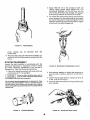
STARTER DISASSEMBLY
1. Loosen the M terminal nut on the solenoid switch
and remove the connector to the starter
assembly. Then unscrew attaching screws and
remove the solenoid switch (Figure 40).
LEVER ASSEMBLY
The packings lor the solenoid swilch are mounted so that the
sleel packing ls localed in the tront bracket side.
LEVER SPRINGS
SPRING dOLDER
@'
_ ARMATURE
SOLENOID SWITCH
FIGURE 42.
ARIIATURE REMOVAL
the ring after driving the pinion stopper
toward the pinion gear using a cylindrical tool as
shown in Figure 43. The overrunning clutch and
4. Remove
FIGURE 40, SOLENOID SWITCH REMOVAL
the pinion stopper should be
2.
removed
simultaneously.
5. Two of the fou r brushes have been soldered to the
brushholder (Figure 44). The brush springs can
be removed from the brushholder.
After removing the through bolts, the starting
motor can be divided into three parts - the front
bracket, housing and rear bracket. The spacing
a
2.
Apply SAE 20 oil to the armature shaft and
splines. Apply grease (Shell Albania No. 2 or
equivalent) sparingly on the shift lever pin, the
joint of the shift lever and plunger, the plunger
and spacing washers at the end of the shaft.
3. To mount the overrunning clutch; first insert the
pinion stopper into the armature shaft, then apply
the ring to the groove of the shaft rigidly. For the
insertion of the ring,use a tool as shown in Figure
45 and pull the pinion stopper up.
FIGURE
43.
RING R€MOVAL
brush springs can be removed f rom the
brushholder.
6. The pole shoes may be removed if necessary, by
removing the flat head machine screws from the
f
rame.
STARTER REASSEMBLY
lnspect the parts carefully in accordance with the
procedure described in "lnspection of Parts". Make
FIGURE 45. MOUNTING OVERRUNNING CLUTCH
any repair necessary. Reassembly is the reverse of
disassembly. Take the following precautions.
1. Clean all of the parts carefullywithadry cloth and
compressed aii it it is availa-ble
4' Use spacing washerg to adjust the armature to
give end play of 0.004 to 0.02 inch (0.102 to 0.51
mm).
Do not use steam or high pressure water to
clean the starter. Olherwise, water particles
are enlrapped in the slarter after reassembly.
5.
Do not immerse bearing-equipped parts in ileaning lluid. Clean
these parts with a brush dipped in "Varsol" or any other comparable mineral spirits. Do not immerse overrunning clulch in cleaning
solvenl. Thoroughly dry any parls thal come into contact wiih lhe
cleaning lluid.
FIGURE
44,
STARTER BRUSHES
Tighten the through bolts to a torque of 35 to 44
in-lbs. (0.40 to 0.51 kg/m).
lnsert the shift lever as shown in Figure 46 into the
front bracket.
FIGURE
30
46.
INSTALLING SHIFT LEVER
conductors are joined to the commutator bars for
loose connections.
INSPECTION OF PARTS
Testing Armature for Short Circuits
Place the armature in a growler and hold a thin steel
blade parallel to the core and just above it while slowly
rotating the armature in the growler (Figure 47'). A
shorted armature will cause the blade to vibrate and
be attracted to the core. Replace shorted armature.
Testing Commutator Runout
Place armature in a test bench and check runout with
dial indicator (Figure 49). When commutator runout
a
exceeds 0.004 inch (0.102 mm) reface the commutator.
FIGURE
FIGURE
47.
CHECKING COMMUTATOR RUNOUT
Testing Armature Shaft Runout
ARMATURE SHORT CIRCUIT TEST
Testing Armature for Grounds
Touch armature shaft or core and the end of
49.
The armature shaft as well as the commutator may be
checked. See Figu re 50. A bent armatu re often may be
straightened, but if the shaft is worn, a new armature
is required.
each
com mutator bar with a pai r of oh mmeter leads (Figu re
48). lf the ohmmeter reading is low, it indicates a
grounded armature. Replace grounded armature.
Testing Armature for Open Circuit
The most likely place for an open to occur is at the
commutator riser bars. lnspect the points where the
FIGURE
50.
CHECKING ARMATURE SHAFT RUNOUT
Testing Field Coils for Grounds
Place one lead on the connector and the other on a
clean spot on the frame after unsoldering the shunt
f ield coil wire (Figure 51). lf the ohmmeter reading is
low, the fields are grounded, either at the connector
or in the windings.
FIGURE
48.
ARMATURE GROUND TEST
3l
lnspection for Brush Spring Tension
Measure brush spring tension with a tension meteras
shown in Figure 54. Push the brush and take a reading
just as the brush projects a little f rom the brushholder.
On a new brush the spring tension should be 49 to 59
ounces (1390 to 1670 grams) for begin Spec J CCKA
engines, 29 to 38 ounces (820to 1075grams) forSpec
G engines.
FIGURE 51, FIELD COIL GROUND TEST
Testing Field Coils lor Open Circuit
Place one lead on the connector and the other on a
clean spot on the brushholder (Figure 52). lf the
ohmmeter reading is high, the field coil is open.
Check the other three brushholders in the same
FIGURE
manner.
54.
MEASURING BRUSH SPRING TENSION
INSPECTION AFTER OVERHAUL
1. For no load test, the starting motor is wired as
shown in Figure 55 and run. The value of the
meter reading at this condition should be as
follows:
Begin Spec
Voltage
RPM
Max. Current
Draw (Amp)
10.5
5000
53
J
Spec G Only
11.5
3700
60
The conductor lor this test should be large enough and as
shorl as possible. ll anything is wrong in the aboye test,
SWITCH
FIGURE
52.
FIELD COIL OPEN CIRCUIT TEST
lnspection ol Brushes
When brushes are worn to the wear limits as shown in
Figure 53, replace them. See that the brushes move
smoothly in the brushholders.
T
WEAR
I
0.55
LIMIT
BATTERY
VOLT
METER
rN
( 14.0 MM)
0.28 rN.
BEGIN SPEC
SPEC
J
FIGURE
53.
RPM
_L
(7. i MM)
T
STARTING
MOTOR
INOICATOR
G
FIGURE
BRUSH WEAR LIMITS
32
55.
WIRING STARTER FOR NO LOAD TESTS
inspect lhe lollowing items:
adjust pinion clearance, connect the battery to
the starting motor as shown in Figure 56. This will
allow the pinion of the starting.motor to slide and
stop. ln this state, measure the clearance between
the end of the pinion and pinion stop when the
2. To
Annealed brush springs
lmproperly seated brushes
lnsulf icient armature endplay
Shorted, open or grounded armature
Grounded or open field coil
Poor elecliical connection
Dirty commutator
STARTING
MOTOR
pinion is pushed lightly toward the commutator
end. Clearance should be 0.02 to 0.06 inch (0.51 to
1.52 mm). Adjust for proper clearance by removing the solenoid switch attaching screws and
select the proper thickness of the fiber packings
shown in Figure 57.
BATTERY
FIGURE
FIGURE
56.
BATTERY COT{NECTIONS
33
57.
ADJUSTING PINION CLEARANCE
PARTS CATALOG
INSTRUCTIONS FOR ORDERING REPAIR PARTS
For parts or service, contact the dealer from whom you purchased this equipment or refer to your Nearest
Authorized Onan Parts and Service Center.
To avoid errors or delay in filling your parts order, please furnish all information requested.
Always refer to the nameplate on your unit:
1. Always give the MODEL and SPEC NO. and SERIAL NO.
For handy reference, insert YOUR engine
nameplate information in the spaces above.
2. Do not order by reference number or group number: always use part number and description.
3. Give the part number, description and quantity needed of each item. lf an older part cannot be identif
ied,
return the part prepaid to your dealer or nearest AUTHORIZED SERVICE STATION. Print your name and
address plainly on the package. Write a letter to the same address stating the reason for returning the part.
4. State definite shipping instructions. Any claim for loss or damage to your unit.in transit should be filed
promptly against the transportation company making the delivery. Shipments are complete unless the
packin.g list indicates items are back ordered.
Prices are purposely omitted from this Parts Catalog due to the confusion resulting from fluctuating costs,
import duties, sales taxes, exchange rates, etc.
For current parts prices, consult your Onan Dealer, Distributor or Parts and Service Center.
"En esta lista de partes los precios se omiten de proposito, ya que bastante conf usion resulto de f luctuaciones
de los precios, derechos aduanales, impuestos de venta, cambios extranjeros, etc."
Consiga los precios vigentes de su distribuidor de productos "ONAN".
34
This catalog applies to the CCKA Engines listed below. Parts are arranged in groups of related items. Each
illustrated part is identified by a reference number corresponding to the same reference number following the
illustration. Parts illustrations are typical. Using the MODEL and SPEC NO. f rom the engine nameplate, select the
PARTS KEY NO. (1,2, etc., in the last column) that applies to your Engine Model and Spec No. This PARTS KEY
NO. represents parts that differ between models. Unless otherwise mentioned in the description, parts are
interchangeable between models. Right and left engine sides are determined by FACING the blowerend (f ront) of
the engine.
PARTS KEY NO.
MODEL AND SPEC NO.
ccKA-MS/1831G"
1
ccKA-MS/1897G"
2
ccKA-MS/1949G.
3
ccKA-MS/2043G'.
4
ccKA-MS/2111G't
5
ccKA-MS/2813J.
6
ccKA-MS/3110J'
7
ccKA-MS/3612J'
I
' - The Specilication
Letter Advances (A to B, B to C, etc.) with
manufacturing changes.
f - CCKA-MS/2567G
is replacement engine for
CCKA-MS/2I 11G and is identical.
INDEX
GROUP TITLE
PAGE NUMBER
. . .35
|NTRODUCT|ON.
DATA TABLE
Alternator, Flywheel
Block, Cylinder
.. . . 36,37
....1;......39
Camshalt
Carburetor Parts.
Grankshalt
FuelSystem
.....40
....41
Gear Cover
Governor
Housing,Blower ;....
lgnition
OllSystem
PlstonandConnectingRod
Pump Parls, Fuel .
Servlce Kits and Miscellaneous .
.....
...;......38
.....r.39
.
Starter Motor
ValveCoverandOilBy-Pass
35
.....
....i......37
CYLINDER BLOCK
l5
d
36
CYLINDER BLOCK
REF PART OTY.
PART
f to.
No.
DESCRIPTION
usED
1 tsLOCK ASSEMBLY
110-1770
Key t 2.3 4
1 t0-1911
Key 5,6,7,8
2 517-0048
'Plug, Camshaft Expansion
3 800-0512 5
Screw. Cap - Hex Head
REF
NO
i6
17
1
1
18
j9
1
1
20
-GASKET
1
1
1
2
1
4
5
12
101-0316
1 01 -0367
13
509-0041
14
516-0072
15
1 1
11
0-0445
2
2
2
2
2
2
2
2
2
2
4
4
I
110-0872
110-1000-02
110-1000-05
110-1000-10
110-1000-25
Th rust
KIT. BEARING PLATE
1 01 -041 3
101-01 15
INSERT, VALVE SEAT
110-1000
22
23
110-0902
110-0539
110-0639
24
TAPPET, VALVE
21
ntake
Exhaust
I
2
110-0872-02
110-0872-05
110-0872-10
110-0872-25
1
10
0-1 037
110-0880
4 502-0020
5 110-0892 2
6 1 t0-0884
7 110-0883
8 BEARING,CRANKSHAFT
01 -0450
2 -Standard
101-0450-02 2
.0O2" Undersize
101-0450-10 2
.010" Undersize
101-0450-20 2
.O2O" Undersize
101-0450-30 2
.030" Undersize
9 104-0575
2 .Washer, Crankshaft Bearing
1
1
VALVE
1 1
Rear Bearing, Plate Mounting
(5,'16-18 x 1")
Elbow, Street - Orl Lrne
(Keys 1,2,3,4 & 5)
Gasket, Cylinder Head
Head, Cylinder - Right
(#2 Cylinder)
Head, Cylinder - Left
(#1 Cylinder)
1
PART OTY.
PART
NO.
DESCRIPTION
USED
I 10-0904
4 Rutocap, Valve
851-0005 5 Washer, Lock - Rear Eeartng
Plate (Special)
20-0386
1 'Tube, Crankcase Oil
.Exhaust, Standard
Exhaust,.002" Oversize
Exhaust, .005" Oversize
Exhaust, .010" Oversize
Exhaust, .025" Oversize
.lntake, Standard
lntake,
lntake,
lntake,
lntake,
Key 1,2,3,4
Key 5,6,7,8
'Plate, Bearing (Excludes
Bearing)
'Guide, Valve
Spring, Valve
Lock, Valve and Spring
4
Standard
.005" Oversize
SCREW, CAP HEX HEAD
1 1 0-0879
8 5/16-18 x 1-1/4" lg (Special)
'10 5/16 x 1-3/4" lg (Special)
114-0022
526-0122
18 Washer, Flat - Cylinder Head
Mounting (11/32" LD.x23/32" O.D.
x 10 Ga. Thk)
-Pin,
Dowel - Gearcase
2
51 6-001 1
115-0006-05 4
25
'Bearing, Camshaft Front or
Rear (Precision)
.Seal, Bearing
Plate
'Pin, Main Bearing
.Nut, Rear Bearing Stop
Plate
115-0006
26
27
28
51
1
7-0090
Alignment
Plug, Wet Hole (Plastic)
' - Parts included in Cylinder Block
VALVE COVER AND OIL BY-PASS
REF,
PART OTY.
NO. NO.
USED
6J-,,
3
23-0398
20-01 40
526-0066
4
120-0187
4
801 -0050
.1
801-0048
1
2
to
9
t7-
\
l6-- -'o
1
-p/
5 120-0704
6 123-0953
7 123-0958 2
8 123-0865
9 123-0951
10 509-01 17
1 123-0954
12 TUBE.BREATHER
503-0574
123-1264
13 809-0035 I
14
10-0667
2
15
10-0666
2
16
526-0063 2
-17
l4 H re
@- -
1
gt
1
1
1
1
1
1
17 800-0012
18 503-01 70
37
Assembly
PART
DESCRIPTION
Valve; Oil By-Pass
Spring, Oil By-Pass Valve
Washer, Flat, Oil Pressure Relief
Yalve (25/64" lD x g/16" OD
x 1/16" Thk)
Stud, Oil By-Pass Adjustment
(lncludes Nuts) Keys 1,2,3,4
Screw, Cap - Hex Head
Oil By-Pass Adjustment Key 5
(3/8-24 x 1" lg)
Screw, Cap - Hex Head - Oil
By-Pass Adjustment
1
H
5
Oversize
Oversize
Oversize
Oversize
Retaining
(Key 1,2,3,4,5,8)
l8
.002"
.005"
.010"
.025"
2
I
(5/'16-18
x 1" lg)-
Key 6,7,8
Spacer, Oil By-Pass (Key 5 Only)
Tube, Breather
Screen, Breather Tube
Baffle, Breather Tube
Clamp, Breather Cap
Seal "O" Ring - Breather Tube
Cap, Breather Tube
Keys 1,2,3,4,5
Key 6.7.8
Screw, Cap - Hex Head - Breather
Cap Clamp (#8 x 3/4" lg)
Gasket, Valve Cover
Cover. Valve Cover
Washer, Flat - Valve Cover
Mounting (17/64" lD x 7/16" OD
x 1/32" Thk)
Screw, Cap - Hex Head - Valve
Cover Mounting (3/B-16 x 2" lg)
Clamp, Breather Hose
OIL SYSTEM
m
+YY
@hfr
REF. PART
NO. NO.
1 123-1 t02
2 123-0191
3 . 102-0158
4 102-0655
5 122-0320
6 122-0323
7 122-0321
8 193-0005
9 120-0491
l0
l
12
13
14
1s
16
r
I
20-0663
120-0161
120-0689
505-0056
501-0003
502-0017
309-0237
otY.
I
1
1
1
1
1
'1
REF. PART
NO. NO.
't7 502-0058
PART
DESCRIPTlON
USED
1
1
1
1
1
1
1
1
1
udr
2U.--
ro
Cap & lndicator,oil Fill
Gasket, Oil Fill Cap
Gasket, Oil Base Mounting
18
19
Base, Oil
OTY.
USEO
,l
123-0674
1
141-0078
'|
PART
DESCRIPTION
Tee, Low Oil Pressure Switch Key 4.5,6.7,8
Tube, Oil Fill
Gasket, Oil Fill Tube
Mounting
Adapter, Oil Fill
Filter, Oil (Spin-On)
Gasket, Oil Filter Adapter
Gauge, Oil Pressure Key 1,2,3
Pump, Oil - Complete
(NOTE: lnternal parts not
sold separately)
lntake, Oil Pump (lncludes
Cup and SOreen)
Gasket Kit, Oil Pump
Line, Oil Pump lntake
Plug, Oil Drain
Line, Oil Gauge (Flexible)
Connector, Oil Line
Switch, Low Oil Pressure -
20
21
122-0347
800-0005
22 800-0007
23 800-0028
24 102-0455
2s 850-0040
26 850-0040
27 8s0-0050
28 526-0065
Key 4,5,6,7,8
29
30
38
2
Seal, Air - Oil Filter
Screw, Cap - Hex Head - Oil Fill
Tube Mountin g (1 / 4-2O x 3/ 4" lgl
Screw, Gap - Hex Head - Oil Pump
Mounting (1/4-2O x 1" lg)
Screw. Cap - Hex Head - Oil Frlter
AdapterMounting (5,'16-18x 1 'lg)
Screw, Cap - Hex Head - Orl
Base Mounting (3/8-16 x 1" lg)
Washer. Lock - Spring - Oil Fill
2
Washer, Lock - Spring - Oil Pump
4
Washer, Lock - Spring - Oil Base'
Mounting (3/8")
Washer. Flat - Oil Frlter
1
2
2
2
4
Tube Mounting (1/4")
Mounting (1/4")
2
Adapter Mounting
122-0352
'|
815-0194
2
(21i64" lD x 9, 16" OD x 1 16 Thh
Pan. Oil Drain
Screw, Tapping - Hex Head
with ET (#10-32 x 3'8")
r
CAMSHAFT
2-
/\,
/Ai
'rbQ)";
?
REF. PART
QTY,
PART
NO. NO.
USED
DESCRIPTION
1 150-0078
Ring, Camshaft Center Pin
2 150-1695
Kit, Governor Cup
3 510-0015
5
Ball, Fly - Governor
4 105-0004
Washer, Camshaft Gear Thrust
5 515-0001
Key, Camshaft Gear Mounting
6 105-0238
Camshaft (lncludes Pin)
7 150-0075
Pin, Camshaft Center
8 105-0332
Gear, Camshaft (lncludes parts
Marked .)
,Spacer,
I 't50-1257
Flyball
10 150-0077
'Plate, Flyball
1 150-1519
Hub, Governor Cup
12 150-1520
Cup, Governor
- - Parts included in 105-0332
Camshaft Gear
1
1
1
1
1
1
1
1
1
1
1
1
PISTON AND CONNECTING ROD
REF. PART OTY.
PART
NO. NO.
DESCRIPT!ON
USED
1 PISTON & PIN (lncludes Retaining Rings)
2-C1 36
2 Standard
112-0136-05 2
.005" Oversize
112-0136-10 2
.010" Oversize
12-0136-20 2 .O20"Oversize
112-0136-30 2
.030" Oversize
112-0136-40 2
.040" Oversize
2 PIN, PISTON
2-0069
2 Standard
3 12-0003
4 Ring, Piston Pin Retaining
4 114-0203
2 Rod Assembly, Connecting (Forged)
lncludes Bushing and Place Bolts
5 RING SET, PISTON
113-0153 2 Standard
113-0153-05 2
.OO5" Oversize
13-0153-10 2 .010" Oversize
113-0153-20 2
.020" Oversize
113-0153-30 2
.030" Oversize
13-0153-40 2 .O4O" Oversize
6 805-0010
4 Bolt, Place - Connecting Rods
(5/16-24 x 1/4" lgl
7 BEARING. CONNECTING ROD
4 Standard
4-01 45
14-0145-02 4
.002 Undersize
114-0145-10 4
.010" Undersize
114-0145-20 4
.020" Undersize
114-0145-30 4
.030" Undersize
8 1 14-0036
2 Bushing, Piston Pin - Connecting
1 1
5
€5F
1
@
1 1
1
_4
1
1
1 1
1
I
39
1
14-0059
Rod
Washer, Connecting Rod Screw Lock
cmNfrst{#T
13
l3
I
TP
7;
to
REF.
NO.
PART
NO.
12
OTY.
USED
2
PART
DESCRIPTION
CRANKSHAFT
104-0710
104-0774
104-0885
515-0001
2
3
4
5
6
7
8
I
10
11
12
13
14
15
16
17
-
190-0284
190-0285
526-0128
515-0098
104-0170
134-1889
518-0014
104-0043
134-2556
134-0673
515-0094
812-0125
526-0006
850-0035
104-0032
1
1
1
1
1
1
1
1
1
1
1
1
1
1
2
3
Key 1,2,3 & 4
Key 5
Key 6,7,8
Key, Crankshaft Gear
Mounting
"Gear, Transmission Drive
(3-3/16") - Key 4
.Gear, Transmission Drive
(2-5/16"1 - Key 4
Washer, Flywheel Mounting
Key, Flywheel Mounting
Screw, Flywheel Mounting
(Special)
Screen, Flywheel
Lock, Crankshaft Gear Washer
Washer, Crankshaft Gear
Retaining
Flywheel (lncludes Ring Gear)
Gear, Ring - Flywheel
'Key, Transmission Drive
Gears - Key 4
Screw, Roundhead (12-29 x 1/2")
Guard Mounting
3
Washer, Flat (#12) - Guard
3
Washer, Lock (#12) - Guard
Mounting
Gear, Crankshaft
Mounting
1
Order these parts f rom the tracto r manuf actu rer
{0
ffF
FUEL SYSTEM
2g--v-20
ttT
c&
27-4ir32
3
t2
REF. PART
NO. NO.
1 149-0693
40-1 058
2
1
3
GASKET
149-0003
149-0003
LINE, FUEL
1
1
2
1
49-061
1
502-0313
MUFFLER, EXHAUST
155-1065
155-0480
154-0360 2
141-0078
153-0263
154-0356
154-0013 2
149-0045
420-0169
BASE, AIR CLEANER
140-1054
140-1206
1
12
13
14
15
16
Key 1,2,3,4,5,6,7
Key 8
1
1
PART
NO.
sdg-or z+
21
2
22
800-0009
2
23
800-0054
Screw, Cap - Hex Head - lntake
Manifold Mounting (3/8-16 x
24
815-0222
Screw, Machine - Fillister Head
Fuel Pump Mounting (1/4-2Ox
25
26
27
28
850-0040
2
Washer, Lock - Spring -
850-0050
2
526-0063
2
526-0008
1
29
800-0028
4
30
850-0045
800-0004
4
31
32
149-0136
1
Washer, Lock - Spring - lntake
Manifold Mounting (3/8")
Washer, Flat - Fuel Pump Mounting
(17/64' lD x 7/16" OD x 1/32" Thk)
Washer, Flat: Air Cleaner Cover
Mounting (13/64" lD x 7/16" OD
x 1/32" Thk)
Screw, Cap - Hex Head
(5/16"-18 x 1")
Washer, Lock - Spring (5/15")
Screw, Cap - Hex Head
(1/4-20 x 5/8"1
Plate, Fuel Pump Hole Key 8
2"
Manifold, lntake
1
1
Gasket, lntake Manifold
Spacer, Fuel Pump Mounting
Wrench, Carbu retor Adjustin g
1
Key 1,2,3,4,5
1
Key 6,7,8
4t
lsl
1-1/4" tgl
Carburetor Mounting (1/4")
Key 6,7 (Fuel Pump lnlet)
1
Seal, "O" Ring - Air Cleaner
Element, Air Cleaner
Cover, Air Cleaner
Nut, Wlng - Air Cleaner
Clamp, Fuel Hose
Screw, Cap - Hex Head
Carburetor Mounting
(1/4-20 x 1-1/2" l9l
Pump lnlet)
Keys 1,2,3
Key 4,5,6,7,8
Gasket, Muffler
Gasket, Carbu retor Mounting
Bracket and Clip, Choke
Cable
PART
DESCRIPTION
OTY.
USED
140-1055
140-1053
865-0022
503-0301
20
1
1
11
17
18
19
1
1
1
9
10
REF.
NO.
PART
DESCRIPTION
Pump, Fuel - Key 1,2,3,4,5,6,7
(See Separate Group lor
Components)
Clamp, Air Cleaner
Key 1,2,3,4,5
Key 6,7
CONNECTOR, FUEL LINE
502-0002 2 Key 1,2,3,4,5 - (1) Fuel Pump
Outlet, (1) Carburetor lnlet
Key 6,7 - (1) Fuel Pump
502-0395
Outlet, (1) Carburetor lnlet
502-0395
Key I - Carburetor lnlet
CARBURETOR (See Separate Group for Components)
142-0482
1 Key 1,2,3,4
1 42-0593
1 Key 5,6,7,8
CONNECTOR, FUELLINE
502-0020 1 Key 1,2,3,4,5 (Fuel
1
503-0694
6
OTY.
USED
2
FUEL PUMP PARTS
BEF.
NO.
PART
N(t.
149-0693
149-0526
OTY.
USED
1
1
PART
DESCRIPTION
Pump, Fuel - Key 1,2,3,4,5,6,7
Repair Kit (lncludes Parts
Marked')
@.-5
1
1
2
815-0148
4
3
815-0't47
2
4
149.0096
149-0095
149-0582
2
5
6
7
8
9
10
(#G32x5/8")-Retainer
2
149-0672
'Spring
'Spring
Retainer, Valve Cage
Pin, Rocker Arm
Body (Not Sold Separately)
Link and Arm, Rocker
(Sold Only as a Set)
'Gasket, Diaphragm - Lower
516-01 13
12
149-0710
13
149-0858
14 149-0551
15 509-m65
16 149-0404
17 149-0003
18 518-0129
42
'Valve and Cage
'Gasket, Valve
'Diaphragm Assembly
149-0539
149-0675
11
' -
Body (Not Sold Separately)
Screw, Sell Tapping
(*t32 x 7/8"1
Screu Phillips Self Tapping
2
1
1
1
Side
Lever, Primer
Seal, "O" Ring
Spring, Primer Lever
'Gasket, Pump Mounting
Ring, Retainer - Primer
Lever
Parts lncluded in 149-0526RepairKit.
CARBURETOR PARTS
REF.
NO.
PART
NO.
CARBURETOR
142-0482
5
6
7
8
I
10
11
12
13
14
15
16
17
18
PART
DESCRIPTION
Key 1,2,3,4
Key 5,6,7,8
1
Repair Kit, Carburetor lncludes Parts Marked .')
1 42-0033
1
Gasket Kit, Carburetor lncludes Parts Marked ')
1 Screw, Bowl Gover
815-0103
815-0109
2 Scrbw, Bowl Cover
815-0091
2 "Screw, Choke Fly
(4-40 x 3/16")
142-005s
1 Fly, Choke
142-0205
1 . Sleeve Assembly, Choke
(Cover)
SHAFT ASSEMBLY. CHOKE
142-0420
1 Key 1,2,3,4
142-0530
1 Key 5,6,7,8
"Shaft, Float
142-0039
1
'Gasket, Body to Bowl
142-0031
1
'Gasket (1) Float Valve Seat
148-0017
2
(1( Main Adjusting Needle
142-0049
'-Valve and Seat Assembly
1
'Gasket, Nozzle
142-0032
1
'l
142-0285
Nozzle Assembly
142-0361
1
Float and Lever Assembly
145-0008
1
Lever, ldle Stop
142-0593
142-0371
1
'I
2
3
4
OTY.
USED
1
1
142-0040
'|
142-0282
1
142-0035
'I
812-0063
1
815-0072
2
'|
22
142-0369
142-0368
142-0370
142-0046
23
142-0206
1
24
142-OO45
1
25
26
51
5
r
33
20
21
1
1
1
l>c
___-6
W
"Needle, ldle Adjusting
Spring, ldle Needle Adjusting
Spring, Throttle Stop
Adiusting Screw
Screw, Throttle Stop
Adiusting (3/t-32 x 1/2"1
"Screw, Throttle Fly
Fly, Throttle
"Shatt Assembly, Throttle
Nut and Jet Nozzle
Retainer, Main Adjusting
Needle
6-0027
142-0041
27
1
1
1
28
29
505-0008
'I
142-0042
1
30
142-0343
2
31
870-0053
1
32
33
813-0103
1
142-0227
1
-
2A
.v
--P_e
I
9
(4-40 x 1/4"1
19
1@
o-{
.-Packing, Main Adlusting
Needle
Retainer, Main Adjusting
Needle Packing
Pin, Main Adjusting Needle
'Needle, Main Adjusting
Body Assembly (Not Sold
Separately)
Plug, Gas lnlet
Needle Assembly (lncludes
Packing, Nut and Retainer)
" Bushing, Throttle Shatt
Nut, Throttle Stop
Screw, Throttle Stop Clamp
Pin, Choke Stop
Parts iontained in 142-0033 Gasket Kit.
Parts contained in 142-0371 Repair Kit.
13
t2
FLYWHEEL ALTERNATOR
REF. PART
OTY.
NO. NO.
USED
1 STATOR. CHARGING
2
3
4
5
6
7
I
9
10
11
191-0739
1 I 1 -0892
1 91 -0400
305-0478
305-0477
383-0789
32 1 -01 65
332-0529
332-1 338
332-1358
2
56
6
'191-0793
81 2-01
14
813-0109
15
16
17
18
19
850-0040
850-0030
80(F0006
'-
'Holder, Fuse
'Fuse (30 Amp)
'Terminal, Faston
321-0162
13
'
Rotor, Charging Alternator
Regulator, Rectilier
Spacer, Regulator Mounting
'Socket, Connecting
' Housing, Connecting Sockets
323-0488
't2
ALTERNATOR (lncludes Parts Marked
Key'1,2,3,4
Key 5,6,7,8
12
-/
t=
PART
DESCRIPTION
1
1
I
3
2
800-0009
1
800-0047
2
Clamp, Loop Type
Bracket, Conneclor Mounting
Clip, Wiring Harness
Screw, Machine - Round Head
Rotor Mounting (114-20 x
1-1/2" lgl
Screw, Machine - Round Head Stator Mounting (#'10-32 x
1-3/4" 19)
Washer, Lock - Spring (1/4")
Washer, Lock - Spring (#10)
Screw, Cap - Hex Head
(1/4-2Ox7/8"1
r3
Screw, Cap - Hex Head
(1/4-20 x 1-1/2"1
Screw, Cap - Hex Head
(3/8-16 x 5/8")
Parts included in Charging Alternator Stator
STARTER MOTOR
REF. PART
NO. NO.
1
MOTOR. STARTING (For Components see Separate Group)
2
3t
4
800-0050
1
1
1
1
1
1
2
5
102-0455
3
6
7
I
Bs0-0050
5
2
1
191-051
1
-0790
-0734
191-1052
91
1 91
1
64
b@
7&''
f.
fl
PART
DESCRIPTION
OTY.
USED
19t-1 104
191-1 103
191-1108
-
Keyl
Key 3,4,5
Key2
Key 6,7,8
Flange, Starter Motor
Mounting
Bracket, Starter Motor
Mounting - Key 2
Screw, Cap - Hex Head
Starter Motor to Bracket
(3/8-16 x 1" lg)
Screw, Cap - Hex Head
Starter Bracket Mounting
3/8-16 x 1" lE)
Washer, Lock - Spring - Starter
Motor Mounting (3'8")
Spacer, Starter Mountirlg
Seal,
Air
Refer to lactory giving complete Model, Spec and
Serral Number
IGNITION
7
N
30
32
I
I
!lP
A
33
w,"
i
$
PART
NO.
REF.
NO.
Cover, Breaker Box
Gasket, Breaker Box Cover
Cam, Point Gap Adjusting
Point Set,breaker
Support, Resistor Terminal
Condenser, Breaker Points
Clip, Spark Plug Cables
Gasket, Breaker Box Mounting
Resistor, lgnition
Plunger Assembly (lncludes
Plunger and Guide)
1
1
2'l
22
23
24
CABLE,SPARKPLUG-RIGHT
1 8-1/2" - Key 1,2,3,4,5,6
1 67-1 594
1
67-1 596
1
1
7-1/4" - Key 7,8
Coil, lgnition
12 166-0346
13 CABLE, SPARK PLUG - LEFT
Key 1,2,3
17-1/2" - Key 4,5,6
17" - Key 7,8
Diaphragm, Breaker Box
67-1 594
67-1 593
1 67-1 595
1
1
14
15
16
60-0263
PLUG, SPARK
167-0241
167-0237
160-0257
PART
DESCRIPTIOITI
,..1
1 160-0930
2 160-0150
3 160-0075
4 160-0002
5 304-0610
6 312-0069
7 167-0188
8 160-0043
9 304-0060
10 160-0262
11
,OTY.
REF. PAFT
NO. NO.
USED
17 503-0514 i2 ,1
18 160{558
19 1S-0376
20 160-0428
PART
DESCRIPTION
OTY.
USED
1
2
Key 1,2,3,4,5,6
Key 7,8
1
Box, Breaker (lncludes
2
Points, Condenser, Cover and
Gasket)
45
160-0349
1
334-0028
1
160-0261
1
1
66-0s62
'1
25
26
27
28
802-0034
870-0053
854-0010
2
2
81 3-01
1
29
850-0030
1
30
304-001 4
2
31
850-0040
81 5-0201
2
32
33
821-0004
2
34
336-0332
1
1
2
2
2
Clamp. Coil
Nipple, Rubber - Coil
Bracket, Coil Mounting Key 1,2,3
Strap, Point Set to Terminal
Block
Block and Terminal AssemblY
Lead (4 ft. piece of wire)
Wick, Breaker Box Oil Drain
Bracket, Coil Mounting Key 4,5,6,7,8 Screw, Cap - SocKet Head
Nut, Coil Terminal (10-32)
Washer, Coil Terminal (#10)
Screw, Resistor Mounting
(10-32 x 2-1/2"1
washer, Lock - Resistor
Mounting (#10Washer, Centering - Resistor
Mounting
Washer, Lock - Spring (1/4")
Screw, Machine - Round Head
with ET (#8-32 x 3/8")
Screw, Cap - HWH
(#10-32 x 5/16")
Lead. Coil
BLOWER HOUSING GROUP
REF,
NO.
PART
NO.
134-0589
1
2
PART
DESCRIPTION
OTY.
USED
1
HOUSING.BLOWER
134-2025
134-2't99
1
1
1
Housing, Cylinder Air - Left
Key 1,2,3
4
5
Key 4,5
Key 6,7,8
HOUSING, CYLINDER AIR - RIGHT
134-2032
Key 1
134-2094
Key 2,3,4,5
134-2954
Key 6,7,8
32't -0169
Clip, Cylinder Air Housing
815-026'l
Screw, Tapping - HWH
6
821 -001 0
3
.
134-2951
('t/4-20 x't/2")
Screw, Cap - HWH
(1/4-20 x 1/2"1
f
t
t'
6
GOVERNOR GROUP
REF. PART OTY.
NO. NO. USED
1 SPRING. GOVERNOR
50-0698
50-1 264
150-0639
150-0629
1
2
3
4
5
6
7
1
518-0006
't
52-0155
150-1310
I
PART
DESCRIPTION
L^
Kr\Y
Key 1,2,3
Key 4,5,6,7,8
@D*
Joint, Ball
Link, Throttle
Clip, Link End
Swivel, Throttle Cable
Connector - Key 4,5,6,7,8
Bracket, Throttle Control
l6
--tr
Key 4,5,6,7,8
145-0412
I
815-0104
10
8t5-0241
11
516-0059
12
13
14
15
526-0006
862-0001
850"0040
870-0053
3l
16
870-01
17
150-1269
Connector, Throttle
Bracket - Key 4,5,6,7,8
Screw Machine - Fillister Head
Throttle Control Swivel - KeY
4,5.6,7,8(#8-32 x 5/16" lg)
Screw, Machine - Truss Head
Throttle Control Bracket
Key 4,5,6,7 (1/4-20 x 1/2" lgl
Key, Cotter - Throttle
Control - Key 4,5,6,7,8
Washer, Flat - Throttle Control
(15/64" lD x1/2" OD x 3/64" Thk)
Nut, Hex - Throttle Control
(1/4-20)
Washer, Lock - Spring Throttle
Control (1/4)
Nut, Hex - Governor Control
(10-32)
Nut. Keps - Governor ConltL.l
(lncludes Washer' f 1 0-32)
Spacer, Throttle Control
Bracket - lGy f, 5,6,7,8
s
\b
\)
2
o9
t2---oF
o
k0*_
l4
GEAR COVER GROI'P
REF.
NO.
509-0008
510-00'13
3
150.Q377
4
7
150-0620
29
51 6-01 30
510-0008
8
51 0-001
5
*
1
1
'l
1
51 8-01
6
1
1
1
4
1
10
11
1
1
1
2
5
50-0635
50-1 297
509-0040
516-0011
1
12
13
14
850-0045
15
SCREW,CAP
800-0032
800-0034
-
-
1
PART
DESCRIPTION
Gasket Kit, Complete Engine
lgnition Tune-Up Kit
Carbon Removal Gasket Kit
Kit, Overhaul
s22-0259
17
'Bearing, Governor Shaft Lower
'Ball, Bearing - Governor
Key 1;2,3
5/16-18x2-'l/4" |9)
Parts lncluded in GearCoverAssembly.
NOTE: For other kits, reler to the group for the part in
question.
168-0109
160-0836
168-0095
'Ring, Yoke Retainer
-Pin Governor - Cup Stop
Key 4,5,6,7,8
.Seal, Gear Cover
Pin, Gear Cover
(5/16 x 1-1/8"1
Washer, Lock - Spring Gearcover
Mounting (5/16")
HEXHEAD - GEARCOVERMOUNTING
4
5/16-18 x 1-314" lg)
SERVICE KITS AND MISCELLANEOUS
QTY.
USED
Upper
.Shaft and Arm Assembly,
Governor
.Yoke, Governor Shaft
1
1
PART
NO.
.Seal, Oil - Governor Shaft
-Bearing - Governor Shaft -
Shaft
Cover Assembly - Gear
(lncludes parts marked .)
103-001 1
1 Gasket, Gear Cover
BRACKET, GOVERNOR LINKAGE
103-0332
9
REF.
NO.
PART
DESCRIPTION
QTY.
USED
NO.
2
1
41,,
PART
WIRING DIAGRAMS
(o
F
c!
o
c
o
N
N
att
c- '
o
N
o
=I
=o
(lt
'6t
-
o
06
o
(v)
(E
o
o
dl
l.L
o
lt
o-
.:o(!
=
o
=o
o
.E
c
.c c
o
.:o
o
o (n3 o
5
I
C)
o
o
o
o
i
o
E
o
vt
o
o\
E
o
Y
sg,
o
o
(t
!
e
-
6
(!
o
a.
e
o
=I
Y
o
o
(t
c)
rt
C'
Crl
o
.
r;i
I
Y
o
o
d
o
2',
/',
?ez?e
-1
i
Lf l'rJ
I
I
-t
Eq)
o
I
i
=
I
Y
o
o
(,
F
ot
€
o
.
v
o
o
I
L
----
- ---
18
N
t
o
iel
i:
el
\9
cz
oa
2
-l
-5
6
i
i
--
N
d)
N
N
\9
3r
at
rl
o
c
-
o
6
-
9
T
?
--
d
o
!
o
e'
o
o
=I
Y
o
o
o9zgz29
-t
I
I
J_
3
{t
f9
t
{i
HARDWARE IDENTIFICATION
rllustrated hardware items are only for identification purposes. All hardware items listed throughout this parts
catalog are steel SAE grade five (5) or lower (zinc plated with clear chromate dip) unless parts description
indicates differently. All dimensions are in inches.
WASHER TYPES
#@
$
@
EXTERNALTOOTH INTERNALTOOTH EXTERNAL{NTERNAL
LOCK
-
(ET)
(IT)
IOCK
TOOTH LOCK
(EIT)
SPBING
LOCK
COUNTERSUNK
EXTEBNAL TOOTH
LOCK
Flat washer dimensions given are: lnside Diameter (lD), Outside Diameter (OD)
and Thickness (Thk).
BOLT AND SCREW TYPES
e*ryryryryryryry
l*-,--J
ROUND
HEAO
BINOER HEAD
TRUSS HEAD
CARRIAGE BOLT
PAN HEAD
HEXAGON HEAD
FILLISTER HEAD
FLAT HEAD
L-
HEXAGON
WASHEB
@@
OVAL
HEAO
SQUARE
HEAD
SOCKET
HEAD
TWELVE
POINT
0lilmililwrilnm,SmffiEffiffiryepfifi@
-L-,--J
L--,-l-t-,--.] L-,---l'
[-,--l L,--J
SLOTTED
SOCKET
ffifu fffu
L-,--.] L-,-l
L - Measure length between these points.
INTERNAL DRIVE TYPES
or screw numbc')
ffir
t-; -J"
**" "*
n
SLOTTEO
RECESSED
(PHILLIPS)
CROSS
I
POINT
SOCKET
SIX
TWETVE POINT
SOCKET
NUT TYPES
E
FULL HEXAGON
m
rm
ar_]
JAM HEXAGON
HEXAGON WASHER
SQUARE
nches
I I l1/4-20 x 3/4"
t/
WING
fi
ACORN
s
I
0NAN
1400 73RD AVENUE N.E.
.
MTNNEAPOLIS, MlNluEsoTA 55432