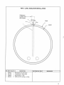
1
M-501-T1 099H2-99
TEXAS
Serial Number:41099
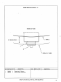
Storage Tank
OPERATION, MAINTENANCE,
SAFETY ANd PARTS MANUAL
a:::
_r-
E. D. ETNYRE & CO., Oregoh, lll 61 061
ASPHALT STORAGETANK
Operation, Safety and Parts Manual
M-501 -T1 099H2-99
TEXAS
41099
HOWTO ORDER PARTS
To assure prompt delivery when ordering parts, please furnish the following information: 1) Complete
name and address of consignee. 2) Method of shipmentprefened. 3) Is shipment to be prepaid or collect? 4)
Serial numbers of units to which parts apply. 5) Complete part numbers and descriptions. 6) Any special
instructions.
Specify unit serial number when ordering parts!
WARRANTY
E.D. Etnyre & Co. warrants to the original Purchaser, it's new product to be free from defects in material and
workmanship for a period of twelve (12) months after date of delivery to original Purchaser. The obligation of
the Company is limited to repairing or replacing any defective part retumed to the Company and will not be
responsible for consequential damages or any further loss by reason of such defect.
The company excludes all implied warranties of merchantability and fitness for a particular purpose. There a¡e
no warranties, express or implied, which extend beyond the description of the goods contained in this contract.
This warranty does not obligate the Company to bear the cost of machine transportation in connection with the
replacement or repair of defective parts, nor does it guarantee repair or replacement of any parts on which
unauthorized repairs or alterations have been made or for components not manufactured by the Company except to the extent of the warranty given by thti original Manufacturer.
This warranty does not apply to:
(1) Normal start-up services, normal maiiltenance services or adjustments usually performed by
the selling dealer, factory service representative or customer personnel.
(2) Any product manufactured by E.D. Etnyre & Co. purchased or subjected to rental
use.
(3) Any product or part thereof which shows improper operation, improper maintenance, abuse,
neglect, damage or modification after shipment from factory.
(4) Any product or part thereof damaged or lost in shipment. Inspection for damage should be
made before acceptance or signing any delivery documents releasing responsibility of the de
livering carrier.
This warranty and foregoing obligations are in lieu of all other obligations and liabilities including negligence
and all warranties of merchantability or otherwise, express or implied in fact or by law.
E. D. ETNYRE & CO., Oregon, lllinois 61061 -9278
1333 South Daysville
Road
Phone: 8151792-2116 Fax:815-732-T4OO
I
ïABLE of CONTENTS
Reporting Safety Defects
a
J
Safety Instructions
General Identifi cation ..........................
4
5
Insulation
Electric Heaters
Float Gauge
Electric Power
Thermometer
Plumbing...
Control Box ...........
Control Panel Inside
Preparation For Use
6
6
6
6
6
6
7
8
9
Connecting Power
...10
General Operating Instructions
...11
Heater Operation
,.. 11
Pump Tank Operating Instructions
,..12
Fill from Transport Tanker
,.. 12
Unloading Storage Tank
.. 13
Cleaning Asphalt Pump
t4
Recirculation .............
15
Wiring - Motors Control panel.........
16
Piping, Motor & P200 Pump Installation ................ t7
Piping, Motor & P200 pump Installation................ 18
Insulation & Heat Shield Installation
t9
insulation & heat shield installation
20
Heater Installation ..
2l
Heater Kit - 28kw/480 Volt ........
22
Pipe-Level Indicator Installation
Bituminous Pump P-200
Sump Installation - 4"
Tank Gauge Assembly
Handrail, Platform And Ladder Assembly ....
ManholeAssembly
Remote Bulb Temperature Control
Temperature Controller, Fenwal
Unitized Hearer Kir..............
Process Heating Co. Warranty
Control Panel Wiring
Schematic
23
24
25
26
27
28
Appendix I
Appendix II
Appendix III
Appendix IV
Appendix V
@ copyright 1999 E' D' ETNYRE & co' AII rights reserved.
No part of this publication møy be reproduced by any means, electronic
or mechanical, wirhout
the express permission of E. D. ETNYRE & co. The enclosed
dmwin[, ,"^ài, the property of E. D. ETNnRÈ
and no part may be copied or used
without the express permissíon of E. D. ETNyRE & CO.
a'co.
2
Reporting Safety Defects
If you believe that your vehicle has a defect which
could cause a crash, injury or death, you should
immediately inform the National Highway Traffic
Safety Administration (NHTSA) in addition to
notifying E.D. Etnyre & Co.
If NHTSA receives similar complaints, it may
open an investigation, Ifit frnds a safety defect exists
in a group of vehicles, it may order a recall and
remedy campaign. However, NHTSA cannot become
involved in individual problems between you, your
dealer, or E.D. Etnyre & Co.
To contact NHTSA, you may call the Auto Safety
Hotline too-free at 1-800-424-9393 (or 366-0123 in
the Washington, D.C. area). Or, you may write to:
U.S. Department of Transportation, 'Washington, D.C
20696. You may also obtain other information about
motor vehicle safety f¡om the Auto Safety Hotline.
E.D. Etnyre & Co., Oregon,Illinois 61061, Phone
Area Code 815/732-2116, Cable Address
..EDECO".CALIFORNIA
A
wnRNlNG
Do not attempt any operation which is not
described in the manuals.
Other operations could cause serious injury
or death.
Read, understand and follow the manuals
when operating or performing maintenance.
A
woRNrNG
Unsafe operation of equipment may cause
injury or death.
Read and understand the manuals before
operating or performing maintenance.
a
A
wnRNrNc
To avoid serious injury or death always
have shields in place when operating.
A IMPORTANT
When filling the storage tank for the first
time, carefully fill until the material level
raises to the top of the manhole collar. This
will cost the interior of the tank with a thin
film of asphalt that will deter corrosion.
3
SAFETY INSTRUCTIONS
Safety warnings have been provided to call attention to any potentially hazardous situation that may cause
property damage, personal injury or death to the operator or bystanders. Theses safety warnings are
identified by the following warning symbol.
A
A
A
A
The DANGER symbol alerts you to immediate hazards which V/ILL result in servere personal
injury or death.
The WARNING symbol alerts you to hazards which may cause severe personal injury or death.
A CAUTION alerts you to procedures that may result in damage to the equipment if not followed
properly.
An IMPORTANT provides general information that the operator should be aware of when performing an operation.
All of these warnings appear throughout the manual.
As with any type of equipment, there are certain hazards associated with improper or careless operation.
The ability to read and understand the instructions in this manual should be a required qualification to
become an operator.
A
A
HoT SURFAcES
Since this tank is intended to store hot liquid asphalt, the surfaces of the tank and equipment may be
hot. All surfaces and equipment should be considered to be hot. Wear insulated gloves and protective clothing to prevent burns. The piping is heated with electric heat tape, it will be hot even
though it has not been used recently.
Hor LreurDS
The liquids stored in this tank are hot. The piping and hoses used to transfer the liquids are hot.
insulated gloves, protective clothing and a face shield when transferring hot liquids, or handling hot liquid hoses to avoid burns. Stay clear of piping that may contain hot liquids. Leave all
valves closed unless you are performing an operation which requires a valve to be opened. Do not
open valves unless you are prepared for asphalt to flow.
'Wear
A
ELEcTRtcAL sHocK
This equþment is powered by high voltage electricity. To avoid electrical shock causing personal
injury or death, so not attempt to make repairs or adjustments without turning the main power off at
the control panel. Do not attempt to operate this equipment with the control panel door open.
A
MoVING PARTS
This equipment contains moving parts, turning shafts, pulleys and belts. Keep all guards in place
when operating. The agitator is controlled by a timer and may start unexpectedly. To avoid entanglement, do not attempt to make repairs or adjustments without turning the main power off at the
control panel.
A
FALLS
To avoid falls that could result in death or serious injury do not climb over the guard rails on to top
of the tank for any reason. Be careful when working on top of the tank to avoid dropping tools or
parts that could strike someone on the ground.
4
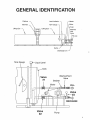
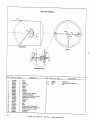
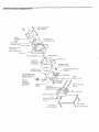
G EN
ERAL I DENTI FICATION
Platform
Level lndicator
Heater
Manhole
Tank Gauge
Motor
Pump
Lifting Eye
Lifting Eye
Washout
Vent
Valve
Fill Line
D
.)=
F
¡l
iþ-=
Sump
Discharge Line
Tank Gauge
Liquid Level
Tank
WashouWent
Valve
#1
Valve
Strainer
Motor
..7
FILL
o
€
Valve
<#3
+
DISCHARGE
)
Valve
#2
Pump
5
INSULATION
The tank is covered with fiberglass insulation, four inches thick. The insulation is intended to maintain the temperature of the heated asphalt. The insulation is covered with .040 Min. aluminum sheeting
for weather protection.
ELECTRIC HEATERS
The tank is heated with a 28KW Unitized Heater. The heater is located inside the bottom of the tank,
it is controlled by a thermostat located in the control box. A light in the control box door indicates when
the heater is on.
FLOAT GAUGE
The tank is equipped with a float type level gauge. The white line on the indicator weight aligns the
tank.
ELECTRIC POWER
Tanks with pumps require 2401480 volt, three phase power, with four wire (neutral wire) system.
Conversion to other voltages is done with wiring inside the control box.
A WARNING
This equipment is powered by high
voltage electricity. Turn main power off at
control panel before making repairs or
adjustments.
THERMOMETER
A dial thermometer is located in a dry well in the side of the tank. The thermometer indicates the
temperature of the asphalt in the tank. The thermometer may be removed from the well with asphalt in
the tank.
A
mRNING
All surfaces and equipment should be
considered to be hot. Wear insulated
gloves and protective clothing to prevent
burns.
PLUMBING
Three inch diameter lines run from the bottom of the tank to the pump. The pump is belt driven by a
five horsepower 2401480 volt three phase electric motor. It may be used to pump out of the storage tank
into other small tanks, or used to pump into the storage tank from transport tanks. The system may also
be used to recirculate the product in the storage tank. All lines are insulated and heated with 115 volt heat
tape.
6
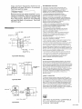
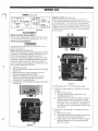
CONTROL BOX
The control box is located on the side opposite the ladder. In the door of the control box is a master
disconnect or switch which controls power for all of the electrical functions. A heater indicator light is
also located in the door, indicating when the heaters are on. Apump, forward, off, and reverse switch will
be located in the control box door as well. Inside the box are the various fuses and contactors to operate
the electrical equipment. A timer for the agitator and the thermostat for the heaters are located inside the
control box. Also located inside the control box is a 115 volt receptacle (GFI), that may be used for
powering lights or hand tools up to 15 amp capacity.
ON
OFF
OPEN
COVER
@
TEMPERATURE
GAUGE
WINDOW
LOW LEVEL
FORWARD
REVERSE
srop
I-IEAT ON
-.H HH
-ffi
16
ffi
HI LIMIT
PUSHTO RESET
@
Storage Tank Gontrol Panel
Outside View
¡[, onncER
This equipment is powered by high voltage electricity.
7
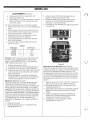
CONTROL PANEL INSIDE
I
7
10
1. GFCI/Heat Trace Transformer
2. Control Power Transformer
3. ICE Relay
4. Sectional Terminal Block (3-sections)
5. Main Tank Temperature Control
6. Tank High Limit Temperature Control
7. Heat Trace Contactor
I
9. Heat Trace Fuse Block
10. Reversing Motor Start-up Pump
12. Motor Protection Reversing Starter
14. Tank Heater Fuse Blocks
15. Tank Heater Contactors
16. GFCI Receptacle
17. Heat Trace Temperature Control
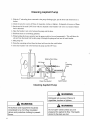
PREPARATION FOR USE
INSPECTION
Unpack the ladder, ladder cáge and handrail. Check for damage that may have occurred during shipment. Visually inspect the tank, particularly the tank jacket and insulation for damage that may have
occurred during shipment. Report any damage to the driver delivering the tank.
SETTING TANK IN PLACE
1. The tank level gauge float has been secured to the roof of the tank for shipment.
2. Install ladder, ladder cage, handrails and platform. Securely tighten all fasteners
A
wnRNrNG
I
To avoid falls that could result in death or
serious injury, do not climb over the guard
rails on top of the tank for any reason.
A *lRNtNG
Keep all guards in place when operating
9
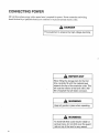
CONNECTING POWER
480 volt three phase power with a neutral wire is required for power. Power connection and wiring
should be done by a qualif,red electrician to conform to local and national electric codes.
A DANGER
This equipment ís powered by high voltage electricity
A IMPORTANT
When filling the storage tank for the first
time, carefully fill until the material level
raises to the top of the manhole collar. This
will cost the interior of the tank with a thin
film of asphalt that will deter corrosion.
A
wnRNrNG
Keep all guards in place when operating.
A
wlRNrNG
To avoid falls that could result in death or
serious injury, do not climb over the guard
rails on top of the tank for any reason.
10
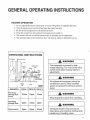
GENERAL OPERATING INSTRUCTIONS
HEATER OPERATION
1. Do not operate the heaters unless there is at least 700 gallons of asphalt in the tank.
2. Turn the master power switch off and open the contro box door.
3 Set the desired temperature on the thermostat knob.
4. Close the control box door and turn the master power switch on.
5. The heaters will turn on and off automatically to maintain the set temperature.
6. The indicator light on the control box door will turn on whenever the heaters are on
OPERATI NG INSTRUCTIONS
Tank Gauge
Liquid Level
A
Tank
This equipment is powered by high
voltage electricity. Turn main power off at
control panel before making repairs or
adjustments.
WashouWent
Valve
Valve
#1
Strainer
Motof
wnRNrNG
FILL
€
Valve
€#3
A
+
rll
DISCHARGE
Valve
Pump
#2
520030
Operation
Valve
Fill Using
Storage Tank
Pump
Glose
Unloading
Storage Tank
Open
Close
Open
Recirculation
Open
Open
Close
1
Valve 2 Valve
Open
1
3
Close
*oRNrNG
All surfaces and equipment should be
considered to.be hot. Wear insulated
gloves and protective clothing to prevent
burns.
A
wlRNrNG
Keep all guards in place when operating
A
wlRNrNG
The liquids stored in this tank are hot.
Wear gloves and protective clothing when
transferring or handling hoses.
11
PUMP TANK OPERATING INSTRUCTIONS
Fill from Transport Tanker Using Storage Tank pump
1. Connect the transport's hose to the outlet line on the transport tanker.
2. Connect the hose from the transport tanker to the 3 inch
fill
line on the storage fank. Be sure
Fill
Line Valve is closed.
3. Open the Valve on the storage tank and on the transport tanker.
4. Start the pump on storage tank.
5. Watch the tank level gauge on the storage tank to protect against over
filling the storage tank.
6. Close the valve on the transport tanker.
7. Clean the hoses as directed by the transport tanker operating instructions.
8. Close Valve on storage tank.
9. Shut offpump.
10. Disconnect the hose from the storage tank and install cap.
Step 3 OPEN
Step I CLOSE
Step 2
I
!
I
I
I
I
I
I
I
I
I
I
f
rru-
+
DISCHARGE
I
Fill from Transport Tanker
A
*oRNrNG
Do not open valves unless you are
prepared for asphalt to flow. The liquids
stored in this tank are hot.
A
*nRNlNG
All surfaces and equipment should be
considered to be hot. Wear insulated
gloves and protective clothing to prevent
burns.
t2
A
woRNrNG
The liquids stored in this tank are hot.
Wear gloves and protective clothing when
transferring or handling hoses.
Unloading Storage Tank W¡th Storage Tank Pump
lnto Asphalt Distributors Or Kettles
1.
Connect the hose to the discharge pipe on the storage tank pump.
2. Connect the other end to the distributor or kettle being loaded.
3. Open the valve between the storage tank and the pump on the storage tank.
4. Open the valve between pump and the hose.
5. Open the valve on the distributor or kettle being loaded if there is one.
6. Turn the pump switch forward.
7. Before the distributor or kettle is completely full, close the valve on the storage
8. Shut off pump.
9. If there is a valve on the distributor or kettle, close it.
tank.
If you
are loading the distributor or kettle through a top opening, raise the end of the hose above the
level of the liquid in the distributor or kettle.
11. Open the valve between the storage tank and the pump,
10.
12. Turn the pump switch to reverse, and draw the material from the hose and pump
it back into the
storage tank to clean the hose.
13.
If
the hose is connected to piping on the distributor or kettle, crack open the hose connection or open
the breather vent valve on the distributor or kettle if there is one. This will allow air to flow through
the hose to clean it.
14. Disconnect the hose
3
from the distributor or kettle and raise the end so that any asphalt remaining in
the hose can drain back to the pump.
15. Once the hose is clean, close the valve between the storage tank and the pump.
16. Shut
offpump.
17. Close the valve between the pump and the hose.
A WARNING
Step 3 OPEN
Step 7 CLOSE
Step 11 OPEN
Step l5 CLOSE
Do not open valves unless you are
prepared for asphalt to flow. The liquids
stored in this tank are hot.
Çnr-r-
r-f
DISCHARGE
+
)l
Step 1 CONNECT
Step 4 OPEN
Step 17 CLOSE
Unloading Storage Tank
A
wnRNrNG
All surfaces and equipment should be
considered to be hot. Wear insulated
gloves and protective clothing to prevent
burns.
A WARNING
The liquids stored in this tank are hot.
Wear gloves and protective clothing when
transferring or handling hoses.
13
Cleaning Asphalt Pump
1. V/ith the 3" unloading hose connected to the pump discharge pipe, put the loose end of the hose
in
a
bucket
2. Check the area for sources of flame,
lit cigarettes,
torches or lighters. Extinguish all sources of flame.
3. Put the end of the small (3/8") hose which is attached to the breather vent valve in a bucket of diesel
fuel or kerosene.
4. Open the breather vent valve between the pump and the hose.
5. Hold both hoses to avoid being splashed.
6. While holding the hoses securely, turn the pump switchto forward momentarily. This will draw the
solvent from the diesel fuel bucket, pump it through the pump and out into the catch bucket.
7, Shut pump off.
8, Drain the remaining solvent from the three inch hose into the catch bucket.
9. Close the breather vent valve between the pump and the 3/8" hose.
WashouWent Valve
3/8" Hose
3u
Qnr-r-
Unloading
Hose
(
i
Diesel Fuel Buckel
Catch Bucket
Cleaning Asphalt Pump
A
woRNrNG
Extinguish all sources of flame, lit
cigarettes, torches or lighters.
A
*nRNtNG
All surfaces and equipment should be
considered to be hot. Wear insulated
gloves and protective clothing to prevent
burns.
l4
A
*aRNtNc
Do not open valves unless you are
prepared for asphalt to flow. The liquids
stored in this tank are hot.
Recirculation
1. Check that
2.
3.
the caps are on and locked on the
fill
and discharge lines.
Close the valve at the end of discharge line.
Open the valve in the
fill line between the tank
and pump.
4. Open the valve in the discharge line between the tank and pump.
5.
Start pump.
Step 3
Step 1
CAP ON
OPEN
f
)
I
I
I
I
I
I
a
DISCHARGE
+
I
I
I
I
Recirculation
rrr-r-
Step 4
Step 2
OPEN
CLOSE
Step 1
CAP ON
A
wnRNrNG
Extinguish all sources of flame, lit
cigarettes, torches or lighters.
A
wlRNrNG
Do not open valves unless you are
prepared for asphalt to flow. The liquids
stored in this tank are hot.
A
wlRNrNc
All surfaces and equipment should be
considered to be hot. Wear insulated
gloves and protective clothing to prevent
burns.
15
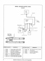
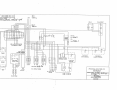
WIRING. MOTORS CONTROL PANEL
5200299
Low
Level
6, 8, 9,10
1,3,5
__7
Control
Panel
Thermowell
Approx.
24" Apart
1,3
1,3
g
6,8,9,
10
6,8,9
Pump
Cover
To Heat
Tape
1
,3,4,11
5HP
Heat Tape
lnstallation
REF
I
)
J
4
5
6
7
8
9
16
PART NO.
QTY
6700969 6
6700858 I
6702282 7
67009't0 I
0t44042
1
6700710 25ft
6000698
6
6702304 25ft
4100110 25fr
1,2,3, 12, 13, 14
DESCRIPTION
Connector-FEMT, 0.50IN, Lqd, Res.
Cord Grip-Male, 0.50x90, Lqd, Res.
Nut-Conduit, l/2 In Sealing
Connector-Femt, 0.50x90, Lqd. Res.
Bushing-Pipe, 0.75x0.50NPT, PD
Conduit-FEMT, 0.50, Sealrite EF
Clamp-Tube, l5/l 6, Berg#l5 1 I -7
Wire-l0GaAWG, White, Type TIIV/N
Wire-lOGa AWG, Black, Type TIIWN
REF
10
PART NO.
QTY
6702499 25ft
4100107 6
t2 6700349 I
r3 6't00023 I
t4 4100105
11
1
DESCRIPTION
Wire-lOGa AWG, Green, Type TIIWN
'Wire
Nuçl0GA
Cover-Unilet K50 Form 35
Gasket-O.5 In Box #GK50-N
Unilet-l/2 LB50-M
Specify Unit Serial No., Part No., & part Description
I
HEATER
I
i
L
I
I
I
I
fYP
I
6
I
25
T
Iz
I
I
F'
=
o
-{
o
¡
5 7/16
RT]AT]SI OE
L__-----
ee
('t!
N)l\,
47 l/2
ll
oo
oo
29 5/g
I
8ë
TYP
I
!
=
TYP
zØ
-{
Þ
¡-
t-
n
i
I
z
5 t/2
I
(
-{
õ
2
!
\
-I
Ji
*J
I ll/t6
JACKE
T
42 ll/16
\
4
| l,/16
2S
2t 9/16
t6 l/8
/4
TYP
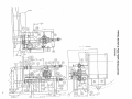
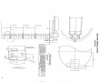
PIPING, MOTOR & P2OO PUMP INSTALLATION
5200280
3l
30
29
28
27
26
25
24
23
22
VALVE MARKER-TRANSFER
S1 1764G
3
CHANNEL-MTR&PUMP MTG HÚRIZ ,16-1/B
CH ANN E L M T R & P U MP MT G H! R I Z
C H AN N EL M D T n R & PUM P M ! UN ï I N G
5200283
I
=200282
520028 I
5200054
5200056
4
I
I
PIPE-3" X 13-9/16,
PTPE-3" X 1_T/2,
PIPE_SCH40,3' X 5_5/8 LG
PIPE-SCH40,3" X 6-1T/16 IG
I
'
=200276
5200275
5200274
660005
I
40 o274993
2T
20 40 ot22I4=
tg 2 62006 i I
6200514
IB
I
5200 1 96
l7
3340004
I
I6
860028 I
2
l5
l4 2 F600277
i3 I 5200053
8500079
I
r2
3380479
I
11
I
5200062
t0
1
VALVE-GATE, HDSE
NU T
ot44071
B
I
5200063
7
6
I
2
3
2
3
5
2
I
I
5
4
3
REF RE6
REMOVE
ALL
T,/VENT VALVE TNSTL
STRAINER ASSEMBLY
CAP-DIIST,3 IN,ALIIM, W,/CHAÏN
AD APT 3
ïN
PIPE-3"
X
CAP
W
EL L TE M P
C ¡NT R¡ L
G REE
=-7/16
E T PE 3 T N 77
DESCRIPTÏ!N
E,D,ETNYR E&f¡
TJK
OFTR
!REG¡N
ALL OIMENSIENS
IL,
IN INCHES
61061
OI] NTT SCALE
DVIG
DRAWING TITLE
OPÏION
TELERANCE
18
SUCTIEN
F L G t+4 2 o05 6 A 3 FL U E D A LEG NY CPL G
G AS K E T 3 F L A NG E A # i o 2 3 3B A S B
L GA T E G 1 0 1 : 3 A LL E GHE N Y L
PU MP U N ï T A s M -P 2 0 0 P UMP 5H P
UNLESS SPECIFIED
UNLESS SPEClFIEO
FRACTIONAL + I/32
xxr .03
,xxxr,0r0
ANGLESI
PIPING,4'4I]TER
0vlG
DECII.4AL
,xr.I
,
-
T HE R ME
C! U PL I NG
BENO RELIEF SHTP
EHART
7g_T/T6"
I
EV R T TE
A
WELL AS M-THERMÚI¡UPLE,8 I/4'
CE UPLING-PIPE, O ,75,PD
TEE & THERMECDUPLE WELL ASM
PIPE_SCH40,3' x 22-l/A LG, VrC
VIC
PIPE_SCH40,3" x
BREAK SHARP ED6ES
I,lINIMUI'4 EENO RAO.
FINISH
AL U M P R T
BOX-STUFFING GE #64440
BURRS
WEIGHT |
PD
EA
WASHilU
6445059
6000088
600007 I
6600045
5200262
PART N!
SER,N0: 41099
SIM,T0: Al077PH
I
I ,2=, GRZ, PD
SfREW-HEX
ELBEW-WELD,45, 3.00, LG RAD
TEE-STRAIGHT, 3IN, PART N 020
=200279
A I O77PM
GENERAL NDTES:
3
HE X LO K 0 3 N f
f
LG
INCH
O . 3BNCX
1
I
x 3-1/A
PIPE_SCH40,3"
1
g
RECRG
RECRG
O.30'
REV
I]RAWIN6 NE
SIZE
0
SEALE
& PzOO PUMP INSTAL.
5200280
I/8
DATE
g/11/94
SHEET
I TF
I
INSULATION & HEAT SHIELD INSTALLATION
5200297
ri
I
I
i
F
7
r
-
!-+
)û
J
f
E
I
UØ
\:
ü
N
z
o
F
)f
Ø
z
u
u
2
q
J
I
J
E
U
=
u
F z
ts
Øu
=<
UL
g<
U
o
J
.'<JO
u
UtsU
tØ<
ozt
z*ø
Ø
u
@
I
Þ
=
E
@
I
I
f,
F
Ø
FI
ili
::t
'f,-T
LI
þ
I
J
l
[[
t-
l
I_
-'-'\-,/'-'
)
l9
INSULATION & HEAT SHIELD INSTALLATION
5200297
28
27
26
25
24
23
22
21
20
l9
I8
t7
16
15
T4
t3
t2
ll
l0
I
B
7
6
5
4
3
2
I
REF
5200298
2
520020 I
2
6700858
I
6702482
40 6702495
5
6000753
600 I 230
50 6000550
l3 800 I 229
I
52002S0
I
520029 I
I
5200292
I
5200293
I
5200294
I
5200295
2
5200082
I
520007s
520008
I
5200080
B
5200076
4 5200296
I
520028S
I
5200288
I
5200287
5200288
I
5200285
I
5200284
I
5200067
REG
PART NE
1
f E RD G R I P
f H R!M A L ! X
ALL
EFTR
APPO
OPTION
SH T LH
sH LD
SH T RH
lvEIGHT
I
SH T LH
SHT R H
SHT L H
SH]ELD-HEAT, UPPER , SHIRT
T E- Ê N D H E A T S H I E LD U PP E R
P L A T E _E N D H E A ï s H I E L D L ¡W E R
ï
RH
I
P L A E EN D HE Á T S H E L D
L DW E R LH
ANGLE-HEAT SHIELD )¿
ANGLE_HEAT SHIELD 2 45 DEG
SHÏELD-HEAT, IJPPER, LENG
PL A TE C ¡V E R H E A T s H I E L D LEW E R
PLATE-HEAT BEX , SIDE, RH
PLATE-HEAT BDX SIDE, LH
PLATE-HEAT BDX , FRINT
PLATE-HEAT BEX REAR
CEVER-HEAT BlX
DESCR
ALL OIMENSIT1NS
t0Ö.
UNLESS SPEEIFIED
FRAETIENAL T I/32
OECIMAL
,xr .l
, xxt .03
ANGLESi O' 30,
IPTIDN
, ETNYRE&fN,
= !REG!N IL, 61061
T K
,XXXI.OIO
FINISH IHART
20
H EA T
H EA T
PL
TT]LERANCE
SER.NE:41099
SII'4 IE: 5200091
I
S HL D H E A T LN W ER B EV E LED
BURRS
BREAK SHARP EO6ES CHKR
MINIMUM BEND RAO,
UNLESS SPECIFIEO ENGR
BEND RELIEF SHOP
0 5X 0 37 5 # 1 2 06
# R T R ES E ND SE L K T
L E W E R B E E LED
S H LD
LD w E R B E E L ED
SH L D -H E ï L OW E R B E VEL E D
^
SH L D -H E A T L ¡w E R B E VE L E D
1
I
MA L E
WIRE_HEAT TRACE ,10'.// /=T
] NSIJLATI EN_FBRGLASS ,2IN THK,/SF
I N S U LA T I DN ELB D W 3 TH K FE R 3 E L B
SC R E W H E X 0 25 I 4X 0 7 5 T E K 3 P D
INSULATIEN-PIPE 3" THKF ER3" PIPE
SHL D HE A T L I WER BE EL E D s H T RH
1
GENERAL NUTES
REMOVE
SHIELD-HEAI , UPPER LONG, LH
RI NG-FTNISHTNG, VALVE BNDY
1
IN
INCHES
OE NET SCALE
OWG
DRA\./ING TITLE
INSULATIEN & HEAT SHIELI] INSTAL.
u\,JG
SIZE
ORAWING NE
D
scALE l,/8
REV
5200297
oAfE 9/r5/ga
SHEET
1 OF
1
+
ï
q
PAO
r
BRACKEÍ
I
o-l
-30
12
I
PAO
É BR^CXEI
20'( to' -o' ,
f
PAO
ù
BRAIKEI
r20.( ¡o' -0' )
lt
I
ii
I
SEAM
REF
m
I
m
(¡Ð
I\)=
n
m
t9 t/2
UI
I
r
n
HEAI€R IUSE ERACKET
E
-0
{
ú
N
f, o
3 o
¡J
n cJ ú
i
LJI @
c
t
c
c
ß-
zo
7 3/g
N c
o c
o c
N à
u
! À
n n
oI
m
zo
zF
I
I
E
E
INSIDE
ú q
T
Ø
I
7 7/B
I
OF
l5 )/4
SEETION'À_A'
HEATER TUBE I'IOUNTING DETAIL
¡+ Ø
m
õ
n
n
I
U
lUI
t\)
o
o
t\)
Û)
o
-
F
z
I
m
N>
ût+
7\
m
'f¡
\zHø
¿U
ài
q)>
of
c¡ -{
f-H
-iE
z
ft
o
B
+.-
f
4
7 )/E
T
ì-
3
b')
Io
m J
FURNISHED T/HEAIER
3/4
-õØ
tu{
o)Þ
oF
l/2
PFÂR
FÂN T¡IIflII
NFTAfI
REVISIONS
t\)
N
2BKW
APPROVED
DATE
DESCRIPTION
REV
UN IZ=D HEATTR KIT
WITH CONTROLS MOUNTED AND PREWIRED TO HEATER
LOW LEVEL SENSOR SWITCH
CONTROL PANEL TO I NCLUDE.
MAIN DISCONNECT SWITCH WITH THROUGH DOOR OPERATOR
CONTROL POWER TRANSFORMER(FUSED)
HEATER CONTACTORS AND INDIVIDUAL LOAD FUSES FOR EACH ELEMENT
HEATER TEMPERATURE AND HI_LIMIT CONTROLS
5 HP REVERSING STARTIR WITH OVERLOAD PROTECTION FOR PUMP MOTOR
FWD/REV/STOP PUSH BUTTONS FOR PUMP
ALL COMPONENTS MOUNTED, PREW I RED AND FUNCT I ONALLY TESTED
U. L. L I ST I NG AS I NDUSTR I AL CONTROL PANEL
12OV TEMpERATURE CONTROL FOR HEAT TAPE SOL l D STATT W/4" PROB
1 1sV RECEPTACLE(Gl F), 15 AMP
FOR
6"
78" I.D. X 390" (SHELL)
m
I
m
¡
x
o)=
oì¡
or
ON
G)c)
(ox
J<
Þ
@
o
o
TANK
HE I GHT BETWEEN HEATER AND CONTROL BOX
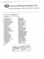
PROCESS HEAT I NG COMPANY,
I
NC. PART
T
2BKW/48O VOLT,3 PHASE
NO
GENERAL NOTES.
DFTR
ALL
CHK R
REMOVE
BURRS
SHARP EDGES
BREAK
MINIMUM BEND RAD.
UNLESS SPECIFIED
BEND
RELIEF
SHOP
JRB
ALL DIM
ENGR
UNLESS SPECIFIED
FRACT TONAL
DEC I MAL
.xl .l
WEIGHT.
XXi
.
OJ
.xxxr.010
FINISH
CHART
ETNYRE&CO
rLS 61061
DO
GON
N
DWC
NOT
APPD
TOL ERANCE
s rM. To, 650038 5
D
ORE
DRAWING TITLE
OPT I ON
SER. NO, A't o99
E
ANGLESl O' 30'
r 1/32
HEATER K I T, 2BKW/48O VOLT
DWG
DRAWING
S IZE
REV
6500391
A
SCALE
NO
NONE
DArE 7/17/98 SHEET 1 OF
'I
PI
PE-LEVEL
I
N
DICATOR INSTALLATION
5200254
Reference
Liquid
Bin-Dicator
Level-+l2
I
L-lEi::-:iñ,
Shell
3,4
Jacket
REF
PART NO.
t
2
3
4
5200253
0187399
5200048
6000434
ow
I
1
I
6
DESCRIPTION
REF
PART NO.
OTY
DESCRIPTION
Pipe-liquid Level, Bin-dicaror
Coupling-pipe, l.O0npt, Steel
Ring-finishing, 1" Pipe
Rivet-dr, 0.19,0.12 Grip, 0.17 Max
23
BITUMINOUS PUMP
P-2OO
3340 593
37
Relief Valve 40
30
PSI
32
0
3l
ll
2l
l2
:-17 .
l3
2
24
PART NO.
REF
QTY
I 33{0331
e 33f0593
7
E
9
to
ll
L2
t3
L7
0r22tl5
0r03ó15
24
H€x 80Lf 3/a x I L/\
PIN-r{OFxlt/+
33r 05 73
2
GA
33t0335
33r033r
3 3r03 r0
ó000r ôt
3r0337
ê6003¡0
33f0307
33r030E
3t
I
BÉ.AR
25
?6
27
29
30
32
3
3
2A
CÂ SE
PUtIP ASr'l-2O0 GAL^rLG RO
SH^Ff¡NO HEAT JACXET¿IIEL
vLv
33f03tf
2L
2?
?3
2ì
OESCRIPTION
ó000¡å 9
331031?
33Ò029r
33tO9t9
0lef613
3 3103 t2
33r03t3
I
t
1
II.G
SKET
IreS¡¡a*
I n eE ¡¡a*
DR
¡VE SFÀFI
I
xËY3/8xL7/1
z
sr'raFl
KEY 3/E X 5
F^CE PLÄ TE
t
!
I
SLEEVE.IIEARING
t
PACX ING
OLANO
2
t
STUD.PACKING GLAIID
?
NUT-HEX, JAl,l, 0. 56NC
I
BY-PISS VALVE TSSETBLY
BY.PASS VALVE FACE PLIÎE
I
I
ct
¡P
il
REF
3?
33
3l
35
36
PART NO.
33t03tt
3
3¡r03¡}5
33103 +6
ó60 0208
33t03t7
02 ¡¿r
37-
6 óO
3E
0e7t501
39
ro
f1
33t03ts
3310319
33t035c
OTY
DESCRIPTION
I V^LVE BOOY
t, SPRJNG
T SPRING BE^RI IC
1 GASXET
I PLUG
T GÂSKEI
I HEX \UT 7./1ó
I
ÌNq SCLf
^OJUST
I G^SKET
1 CÀP
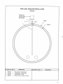
SUMP INSTALLATION . 4''
INSIDE of TANK
L
4" INSULATION
L-----------I
SHELL
I
I
1
2
BELLY of TANK
PAFT NO.
OTY
1
2æ0262
2
6200155
1
1
REF.
DESCRIPTlON
REF.
PART NO.
QTY
DESCRIPTION
Sump Asm-4" Cleanout
Plug-PP,SqHd,4.00NPT,PN
SPECIFY UNIT SERIAL NO., PART NO., & PART DESCRIPTON
25
TANK GAGE ASSET¿|BLY
:l
\i
ROAOSIOE
HEAR
EXPLODED VIEW
REF
I
PARÍ
NO.
QTY.
DESCRIPT¡ON
I
Shåft
I
Spacer
a
AIOTTE.E
3301165
J
3360825
)
4
33011ó3
1
5
6
33Éoty2
1
1
9
3360187
x301164
33ó0828
33Ét20É
t0
0Æ2æ99
J
t
72
0720376
0131002
2
13
A7W7ÊC
l4
I
Nut-Hex, JAM. 1.00NC,PD
Nut-Hex,031NC^PD
WashenFlat. 1.004(1.06 x 250)pD
3360196
t5
AßNTF
I
7
I
u
I
NutAsm
1
Packing
t6
3%1167
I
33ó1r6ó
2
18
A1T77T,Ai
I
I
19
072mt4
20
0121900
9416509
3341199
2
Ttfr593
I
2t
22
z3
2
I
t(
¿6
SGew-1"NC
Sp.ing
Sleeve
Spacer
t7
24
Gasket
1
1
REF
PART
NO.
3360851
3380578
7377
ATY.
DESCRIPf
1
Pointer.¡r"sm
1
DiaI Blank-Trailer Dlstributer
I
Dial
Strdr Asm,78- Dia Tank
DoneÀsm
Spacer
Socket
t€S
Shaft
Washer-l¡ck, 031, Sprin g,pD
Sqew-Hex, 0J5NC x l.OO,cR2.pD
Nut-Hex, Lock, 025, GR2^pD
Cover-facket
Pad-Ring
26
spEc¡Fy uNtT
SERTAL
NO.,
pART
NO., &
DESCRtpltoN
'ART
ION
HANDRAII- PI.ATFORM & LADDEH ASM
1
5
¿-6
r./"
I
7
7
7
I
7REF
1
.,
î
SPECIFY UN IT SERIAL NO.
,
PARÍ NO,
ATOZGE
6
0?'4993
ATOZGU
7
0720426
8
0120384
9
01z2r94
10
Al(]77GN
11
A107æC
72
AlOZF'R
l3
2750377
14
A1077Ð
15
16
A10ZÆE
0120æ3
t7
0446363
18
AlOZÆG
19
2780138
0722007
2t
07202t4
2.
0122408
0120390
94717T7
24
,
Al(]ZGT
07?5973
aa
7t
Al0zcs
4
20
l9
PAFIT NO.
ow
f
1
1
4
t4
2
6
6
6
6
I
2
4
2
Z
4
4
I
4
4
4
2
2
2
& PART DESCRIPT¡ON
DESCRIPT'ION
HÃndrail Aszr-LH
Ha¡rdrailAsm-RH
I{and¡ail Asm-Rear
S<¡ew-Hex, 0.38NC x 3S0, GR2¡D
Nut-Lock,0.38NC"PD
Base
SGew-Hex,0.50NC x 125, GRAPD
Washer-Lock,0.50,Spring^pD
Sqew-Hex,0.38NC x 2i0. GR¿PD
Handrail Mounting Tube
PlaÉormAsm
Chain Guard
Bracket
Support
Lee
Saew-Hex,0.38NC x 1.00, GI{2.PD
Washer-Flat,0.3lA(0.38x0.88),PD
LadderAsm
Baclcstay
. Ssew-Hex,0.31NC x 0.7S, GI{2¡D
Washer-Lock,0.31,Spring,PD
Sqew.Hex,0.50NC x 1.00, GI{¿PD
Washer-Flat,0.50A, W PD
Nut-Hex,Lock,O.S0NC,EA,PD
27
MÁNHOLE ASSEI,ELY
!.ll
o
ril
REF
PART
NO.
QTY.
DESCRIPTION
I
2600379
I
Cover
2
3
4
A1077EX
2600371
4
Bo I
260037?
4
5
26003 73
26003 76
0 137204
4
6
I
9
10
1l
t2
0103364
0120390
2700248
3390535
3561030
I
I
2
I
2
I
I
I
REF
PART
NO
QTY.
Asm
Asm
Colìar
t-Eye
Hinge Pin
5h
aft
Handle
Asm
Cotter Pin,0.12 x l.50,PD
Cotter Pin, 0.06 x 1.25,PD
I'lasher- Fl at, 0 .50 A, H,PD
Gas keÈ
PI AIE-HARNING, MA¡{HOLE SAFETY
P1 ate-CAUTI0N, HOT SURFACE
28
SPECIFY UNIT SERIAL
NO.,
PART
NO., &
PART OESCRIPTION
DESCRIPT¡ON
PIPE . LEVEL INDICATOR INSTALLATION
Reference
Liquid
Bin-Dicator
Level--+l--- -l
2
.]-d
Shell
3,4
1
Jacket
e
REF
I
2
3
4
PART NO.
5200253
0t87399
5200048
6000434
QTY
I
I
I
6
DESCRIPTION
REF
PART NO.
QTY
DESCRIPTION
Pipe-liquid Level, Bin-dicator
Coupling-pipe, l.O0npt, Steel
Ring-finishing, 1" Pipe
Rivet-dr,0.19, 0.12 Grip, 0.17 Max
29
APPENDIX
I
Remote Bulb Temperature Control
-L
UE
55 Series
..-F
UN
Remote Bulb Temperature
Controllers
ITED ELECTR IC
CO NTR O LS
lnstallation and Maintenance
lnstructions
Pleøse read all
hstructiotwl Líterature carcfully ond thoroughly before stafüng. Refer to the final þage for the lßting of
Líahilitie s ønìI W ørr antie s.
Rec o¡nrnend.ed P rcctíc e s,
GENERAL
Temperature variations sensed by the liquidfilled bulb are hydraulically transmitted through
the capillary to a stainless steel diaphragm
capsule. The capsule operates a lever to
actuate one or two snap-action switches.
Surface Mounting (Types E55 and E55A)
Mount using two enclosure mounting holes as
shown.
tB75
z31g
(9 6;0)
(4
150,71
OLEARANOE
Part I - lnstallation
+10 soREw
2
FOH
HOLS
Tools Needed
Drillwith #25 (.1495) and 5/16" bits
Flatblade screwdriver
't56
5, õ)
LOCATE THE CONTFìOL WHERE SHOCK,
VIBRATION AND AMBIENT TEMPERATURE
@ FLUCTATIONS
ARE MINIMAL.
l
i .,'t'
The control can be mounted in any position.
ril
I
nel to accommodate #6-32 sc
. Hole locations should al ign with
holes in mounti ng bracket (see figure
Also, drill 5/16" diarneter ho le to accommodate
control adjustment shaft. Note: maximum panel
thickness is 1/2 inch.
F4
t.
1.r50 G4.5)
coiling the capillary tube smaller than J/2"
radius. Exercise caution when making bends
near the capillary ends. lf a separable well or
7
656
(1ô,7)
1.313 (33.3)
#6-32NC
4 PLACES
- 2
(PANEL MT'G)
Type E55AS (Mounting)
Top View
immersed in the media, recalibration may be
necessary, in which case follow procedures outlined in Part ll.
shaped to fit the installation. Avoid sharp bends
and coils smaller than 2" radius. Do not bend
"B".style bulbs (3/8" OD), Avoid bending or
R-AT
a7s lz2.2l
control head so that it will sense the same ambient temperatures. Factory calibration, unless
spe.cified othenrrrise, allows for 6" capillary tube
in the sensed medium. If more than 6" w¡tt ¡e
"C" style bulbs (1/8" OD) can be coiled or
250 (63s)
213
Fully immerse the bulb and 6" capillary in the
control zone. For best results it is generally
desirable to place the bulb close to - (but noi
touching) the heating or cooling source in order
to sense temperature fluctuations quickly.
Place the remäining capillary adjacenf to tñe
union connector is used follow separate instructions included.
Making Wirino Connectíons
Wire directly to switch terminals according to
particular requirements of the application. For
HOLE
dual switch Types E55A and ESSAS, if switches
a¡e to be_ set apart, connect wiring so that switch
No. 2 will function at the higher temperature.
LIVE SUPPLY CIRCUITS MUST BE
@ ALL
DISCONNECTED BEFORE WIRING THE
CONTROL. WIRE IN ACCORDANCE WITH
l.500
Adjusting Dual Switch
Types E55A and E55AS
112.71
MÆ(. PANEL
F
L
TI-IICKNESS
350
8el
2.s31 163.3)
55 Series controllers are standardly supplied
with the No. 2 (higher temperature) switch set to
the dial. To adjust switch settings for these
2
controllers, follow the recalibration procedure.
+6-32 TERi¿
SCBEW
NATIONAL AND LOCAL WIRING CODES.
MAXIMUM RECOMMENDED WIRE SIZE IS
#14 AWG.
Set the dial to the same temperature as the test
bath. Using 1/16" allen head wrench, loosen
knob set screw and remove dial, taking care not
to rotate the shatt.
Switch Settings
On dual switch units, both switches are factory
set to actuate together within 5% of range
(switch No. 2 set on dial) but may be set to actuate up to '100% of scale range apart. Either
switch may be set to agree with the dial. See
Part ll-Adjustments.
Start-Up Process
Turn dial and knob to the desired temperature
setting. Controller is ready for operation, Minor
adjustments may be necessary to obtain better
set point accuracy after installing the unit in a
particular process. See Part ll-Adjustments.
Part
ll - Adiustments
Tools Needed
1/16" Allen wrench
Small screwdriver
f@l
v
rHE uNrr rs BErNc usED ro coNÍRor'. A PRocESS, PERFoRM oALIBRA-
TION TEST AFTER ADJUSTMENT. UNIT MUST
REPEAT ON SUCCESSIVE ON.OFF CYCLES.
l.500
{12,
MAX, PANEL
THICKNES S
+6-02
350 88.9)
2.s31 163.3)
TÊRVL SCRFW
Shaft has calibrated flat for easy dial replacement. Using 1/16" allen wrench, turn zero
adjustment, located inside adjustment shaft,
until switch No. 2 actuates. Turn counter clockwise for higher setting, clockwise for lower setting.
Replace dial on shaft. Do not secure. Turn dial
to a higher setting equal to temperature differential ('F or 'C) desired between switches No. 1
and No. 2. Remove dial for access to the No. 1
switch adjustment screw. Using a small screwdriver turn in or out the No. 1 switch adjustment
screw (accessible through opening behind dial).
Replace dial, tighten dial set screw to calibrated
flat. Controller is ready for operation.
For single switeh units the only adjustment
needed is the set screw adjustment in the
middle of the adjacent shaft.
Part
lll - Replacements
Tools Needed
Test Thermometer
Use añ accurate test thermometer (such as a
thermocouple) with its sensing area located next
to the sensing bulb.
1/16" Allen wrench
Small screwdriver
Stabilization
Before making adjustments allow 5 minutes
for the thermãl system to adjust to the bath
temperature.
läù orscoNNEcr ELEcTRTcAL suppLy
S2 so rHAT swrrcH coNTAcrs AND
Set Point Reference
eonnect test lights to the terminals to indicate
switch operation.
Adjusting Single Switch
Tyþes E55 and E55S
TERMINALS ARE NOT ALIVE, REPLACE
WITH IDENTICAL SWITCHES CNLY.
Enclosed Types
Remove cover and adjustment dial; then
remove two (2) flat head screws to dismount
control body from enclosure. Remove the large
rectangular cover plate and rubber gasket from
the bottom of the enclosure, and disconnect
wiring from the switch terminals. lnsert the new
switch(es) and tighten screws, Recalibrate set-
!
General Layout, Exploded Mew
._
switch Adjustment
cover Screws
Switch
Control Body
Mount¡ng Screws
Adjustment
Cover
Calibrated
Knob and Dial
Knob Set Screw
Enclosure A,ccess
to f1 Switch
Adjustment Screw
Enclosure
calibrated Flat
Zero Adjustment
Control Body
Access to
#1 Swrlch
Adjustment
Actuating Lever
Extension Spring
b
Capillary CIamp
Mounting Screw
4
Compensat¡ng Disc
(lnstallwith Curved
Side as Shown)
Used on
Standard
Consenated
Units 0nly
\åL+dJ
Capillary
Clamp
Compensating Bimetal
\À,äs h e rs
Diaphragm
{_
LEV ET
(Flipper ptate)
Th
Assm.
+--._
r
Adjustment Screw
s1 Switch
Switch Mounting
Screws
(Dual units 0nly)
ch Term¡nals
S'#itch lnsulators
Switch li,,| ountinq
Locknuts ----?+
Cover Plate/
and Gasketìng
c
Mounting Scre,#s
ting(s). See Part ll-Adjustments. Rewire the new
switch(es) and place unit back in its enclosure.
Reconnect electrical supply.
Skeleton Types
Remove the two (2) switch mounting screws;
remove the switch(es). lnsert the new switch(es)
and tighten screws. Recalibrate setting(s). See
Part ll-Adjustments. Rewire the new switch(es)
and place unit back in its enclosure. Reconnect
electrical supply.
Dimensions
250 (6s5)
2r] 6¿) RAT
875
+t.al
75
t.
122.2)
6
\
1.750 (44.s)
(16,7)
r,s13 (33.31
RECOiIMENDED PRACTICES
Unrled Electric Controls Company recommends careful
consideration of the following lactors when specifying and
installing UE pressure and temperature units. Before
install¡ng a unit, the Installalion and Maintenance instructions
provided with unit must be read and understood.
. To avo¡d damaging un¡t, proof pressure and max
temperature limits stated in literature and on nameplates
must never be exceeded, sven by surges ìn lhe system.
Operat¡on of the unit up to proof pressure or max temperature is
acceptable on a limited bas¡s (i.e.slart-up, testing) but continuous
operation must be restricted to the designated adiustable range.
Excessive cycl¡ng at proof pressure or maximum
lemperature lim¡ts could reduce sensor life.
. A back-up unit ìs necessary for applications where damage
lo a primary unit could endanger life, limb or property. A high
or low ¡imrt switch is necessary for applications where
dangerous runaway cond¡tion could result.
. The âdiustable range must be selected so that incorrect,
inadvertent or malicious sening at any range po¡nl can not
result in an unsaTe system condil¡on.
. lnstall unit where shock, vibration and ambient temperature
fluctuat¡ons will not damage unit or affect operat¡on. Orient
unit so that moisture does not enter the enclosure via
the electricâl connection.
. Un¡t must not be altered or modilied after shipment.
Consult UE ¡t modification is necessary.
. Monitor operation to observe warning signs of possible damage
to unit, such as drift in set point. Check unit immediately,
. Preventative maintenance/periodic testing is necessary lor cntical
applications where damage could endanger property/ personnel.
. For all appl¡cat¡ons. a factory set unit should be tested before use.
Electrical ratings stated
#6-32NC
4
¡n
literature and on nameplate must not be
exceeded. Overload on a switch can cause damage, possible on the
f¡rst cycle. Wire unit according to local and national electrical codes,
- 2 HOLE
using wire size recommended in installation sheet.
PLACES
.
.
.
Use only factory authorized replacement parts and procedures.
Do not mount unit ¡n ambient temp. exceeding published limits.
For remote mounted temperature units, capillary lengths
beyond 10 feet can ìncrease chance of error, and may
requ¡re re-calibration of set poinl and indication.
(PANEL MT'G)
Type E55AS (Mounting)
LIMIT WARRANTY
1875 l,r7
zSlo
158.¿
OLEAFANOE FOR
+10 soREw
2
t0ô0
HOLE
+t5ó
UE warrants that the product thereby purchased is, upon delivery,
free from defects in material and workmanship and that any such
product which is found to be defective in such workmanship or material w¡ll be repaired or replaced by UE (F O B. UE); provided, however,
that lhis warranty applies only to equipment found to be so defective
within a period of 12 months after installation by buyer but not to
exceed 18 months after delivery by the seller. Except for the limited
warranty of repair and replacement stated above, UE disclaims
all warranties whatsoever with respect to the product, including
all implied warranties of merchantability or fitness for any
particular purpose.
LIABILITY LIMITAT¡ON
The sole and exclusive remedy of buyer for any liab¡lity or seller
for any clarm, including incurred in connection with (l) breach of any
warranty whatsoever expressed or implied, (ll) a breach of contract,
(lll) a negligent act or acts (or negligent fa¡lure to act) committed by
seller, or (lV) an act for which strict liability will be imputed to seller,
is limited to the limited warranty or repair and replacement stated
herein. ln no evenl shall the seller be liable for any special, indirect,
consequential or other damages or like general nature, including,
without lim¡tation, loss of prof¡ts or production, or loss or expenses of
any nature, incurred by the buyer or any third party.
Type E55, E55A
CAPILLA.BY
.500
112
MAX. PANEL
THiCKNES
350
2.ssr (8o,sl
S
2
{6-02
Type E55AS
TERr,r
SCSEW
1
el
UE
UNITED ELECTRIC CONTROLS
P.0. Box 9143, Wateriown, MA 02272-9143 USA
617
926-1000 Fax 617 926-2568
MAPl 0M696
APPEi\DIX
II
Temperature Controller, Fenwal
40018
FEW
r'a
!
INDICATING
TEMPERATURE CONTROLLER
INSTALLATION INSTRUCTIONS
PRINCIPTE OF OPERATION
Control action of these mechanical indicating
temperature controllers is provided through the
principle of lÍeuid volume change, See Figure 1.
With a change in temperature, the liquid in the
sensing bulb expands and contracts, causing the
bellows to actuate the switchrng mechanism.
Ambient compensatron is provided by an expandable push rod assembly mounted on top oi the lever
arm which moves the pointer and switching
mechanism. Changes in ambie:nt temperatures
through a range of 0 to 150'F (- 18 to + 65"C)
expand or contract this push rod assembly to
provide an operating balance for the expansion and
contraction of the bellows assembly within the
actuator housing.
PROCESS DIFFERENTIAL
The process differential is minimum when the
narrow differential switch ts used, when the fastest
responding (smallest diameter)bulb is used, when
the narrowest scale range is used, and when the
sensing bulb is installed in a suitably designed
process and in a location which is close enough to
the heater or cooling device to sense temperature
changes quickly.
In general, it is difficult to predict the operating
differential of a given process. The differential can
SNAPSWITCH ELECTRICAL RATINGS
Standard Differential
15 A,125-250 VAC
0.50 A, 125 VDC
0.25 A, 250 VDC
Narrow Differential: 15 A,125-250 VAC
DielectrÍc Strength: Not less than 15OO VDC or lSOO
RMS-AC for one mlnute between the case and
terminaÌs connected in parallel
ACTUÁfING
PIN
-
L
8EI-LOWS EXPANDS PROVIOING
Âcfl./af¡NG FoRCE tO SWrTCll
ANO INOICATING MECHAN¡SMS
o
o
G
z
ACIUÁÍOÊ SPRING
o
ó
o
F
OP:RATING AE!-LOWS
U
AClUÂTOR HOUSING
o
ñ
LOCK
SPECtFtCAT|Ot{S
HOUSING
The housing (and cover assembly) is made of die
cast aluminum with a gray baked enamel finish. It
is designed to meet the requirements of NEMA Type
4 and 12 (lEC IP65 and IP62). Neoprene or corkneoprene gaskets seal all ports and covers. Even
though the housing is watertight, a separate cover
or shield is recommended to þrotect the controller
from exposure in outdoor applications.
ÑUÎ
OFFSEIA0JUSTOA NUf
swrvELJotNl
EULB
CÀPILLAFV
Figure
1
BULB AND CAPILLARY
Material: Type 316 Stainless Steel bulb and capillary
are standard. Copper capillary is available upon
request.
SERIES 4OO
Temperature ExPosure LimÍts
.
(100.c)
top Iange limit of 300
.
.
3.
- izs"F - 115"C) minimum for instruments with
a top range limit of up to and including 200"F
(
. - IOO"F ( - 75'C)minimum for instruments with a
through 500"F (150 through
260"C)
25"F (5'C)minimum for instruments with a top
range limit of 700"F (370"C)
Maximum temperature is 25F" (15C') above the
4.
5.
Do not bend capiilary closer than 1 1/4 inch (32
mm)to the actuator assembly. However, the
caplllary may be rotated 3ô0" at the actuator
assembly.
Where necessary, allow sufficient length to
provide strain relief loops in the capillary.
Mount bulb and capillary so as to avoid flexing
due to vibration.
WIRING
Awnnunc
top range limit
Preèsure Exposule Limit: Bulb will withstand 400
psi (2.75 MPa) over any temperatule range
INSTALLATION
CONTROLLER LOCATION
The Series 400 Controller housing (including the
controller mechanism and actuator assembly)
should be mounted where the ambient tempelature
is within the limits of - 65 and + 150'F (- 55 and
+ 65'C). The controller is ambient temperature
compensated from 0 to 150'F (- 18 to +65"C). The
controller has high resistance tovibration' However,
avoid mounting the unÍt in areas of extreme
vrbration if possible. If it is necessary to mount the
controller in such a location, use a snapswitch with
a maximum acceptable operating differential.
CONTROLLER MOUNTING
The controller can be surface mounted by using the
three adjustable mounting brackets attached to the
case sides and bottom. Fasten with #10 hardware'
Series 4OO Controllers (except those with
ng)can
Modification
should be
also be panel
68.28 mm)
6.500 in (tOS
high. Four mounting holes are provided in the
ovãrhanging portion at the top and bottom of the
case. Thé holes will accept #B hardware and will be
hidden by the cover. A tempiate for the cutout and
holes is located on Page 7.
BULB INSTÀLI,.ATION
Temperature limitations for the bulb and caPillary
are listed in the SPECIFICATIONS section' For
optimum control, the bulb and 6 in (15 cm)of
cäpillary shouid be immersed in the process'
AwlRnlnc
/n cont¡o/Je¡s with upper range llrnits ol 700'F (370C),
flunging the bu/Þ lrom a very cold temperature into a hot
since
þrocèss couta cause the buJb tc st¡etch or even rupture,
i¡e ¡lu¡d is veryviscous at temperatures below 25"F (-4'C)
Acnurlon-
(2'75
Do not expose bulb to pressures greater .than 40O psi
MPa). Beyond th js po¡nt some creep ¡n the buJb structure
occu¡s wirich introduces offset into the system
CAPILI.ARY INSTALI.ATION
1. Minimum bending radius is 1/4 inch (6 mm)'
2. Do not bend capillary closer than 1/4 inch (6
mm)to the bulb-caPillary weld'
ecopyrtghl 1992 Krdde-Fenwal lnc
-t
t'
SPECIFICATIONS Continued
Highvolt
seve¡e in
qualiÍied
controilerthat cou/dcause
ld onlY be PerÍormed bY
belore wiring Wire in
accordance with )ocal codes
Wiring Entrance
Entrance for winng is provided by
a knockout on
each side of the housing. Remove knockout by
applying one or two sharp blows with a metal or
wooden dowel. Be careful not to damage switches.
To maintain the watertight and dusttight feature'of
the Series 400 Controller, proper conduit connector
fittings should be used.
ln controllers with Explosion-proof Housing
(Modification 110), a sepalate houstng for the
snapswitches and wiring is located on top of the
coniroller. To maintain the explosion-proof feature
of the housing (Class I, Groups C and D, or Class II,
2), wiring must
Groups
that is screwed
enter the
the housing. For
into the
a waterProof
compound on the pipe threads. To gain access to
the snapswitches in the housing, remove the knob
and front panel of the controiler to expose the four
screws on the front of the housing. Remove these
screws and the housing cover,
l
E,
h
1/2
additional
for exampies of wiring
units respectively.
made with generous loops
of wire so as not to impâir switch operation or
marked NO (open below
d NC (closed below set
ce on snapswitch when
maktng connections.
Controllers with additional snapswitches in the
lower compartment (S.F' 75)have prewired and
marked connections as follows:
closad
:Clo¡ed
Cl¡crrh=
iBotrve€n
-N-nltef
2and
F
Note: Switch
1
is
nearest front of controller
SERIES
400
WIRIHG Continued
'...j
^
NO
NC
a'l
Y
H¡A]IXG
to^D
--¡- --.
i¡ coouxc
LOAD
--
I
!
Figure
2A
Figure 28
Model 4O-7O3 (See Figure 4)
This controller has two switches, either one of
which can be adjusted to operate when the pointers
are in alignment. The other switch will either be
above or below the indicated settrng, depending on
whether it is used for overheat alarm, warm-up heat
or some other auxrliary'function, The procedures
are as follows:
ADJUSTMEIITS
KNOB TOROUE ADJUSTMENT
Knob torque is adjustable by means of the set screw
A in the front shaft bearing. See Figure 3, 4, 5 or 6
SWITCH ADJUSTMENTS
A,wann¡nc
Djsconnect power when adjusting snapswitches to avord
possible elect¡ic shock.
.t
I
.J
Model 4O-7O2 (See Figure 3)
When the set pointer is in exact alignment with the
temperature indicating pointer, the switch should
be midway between the Operate and Reset
positions. The Operate position is the point where
the switch clicks on; the Reset positions is the point
where the switch clicks off. The relationship will
usually be upset if the snapswitch is replaced, but it
can be easily restored as follows:
1. Remove top cover.
2. Bring set pointer (B) in alignment with indicating
pointer (C).
3. Adjust screw (E) midway between the two
positions where switch (F) ciicks.
4. Check the setting by placing a screwdrlver
under lever (D) and simulate temperature
changes by moving the iever.
5. if necessary, trim the setting by slight adjustment
of screw (E).
Figure 4
For Differential Up To
t
15% of Scale Length
A. When the upper setting is indicated by the
pointer:
1. Remove top cover.
set
2. Bring set pointer (B) in alignment with
3
indicating pointer (C).
Adjust screw (H)on the front switch to a point
midway between the two positions where
switch (l)ciicks. This switch must always be
the upper of the two settings An attempt to
do otherwise wiil cause the rear switch to be
inoperative.
B. When the lower setting is indicated by the set
pointer:
1. Remove top cover
2. Adiust set pointer (B)the differential amount
lower than the indicating pointer (C).
3. Ad¡ust screw (H)on the front switch to a point
midway between the two positions where
)
switch (l)cticks.
Figure 3
SER|ES
ADJUSTMENTS Continued
4. Bring set pointer (B) in alignment with
indicating pointer (C).
5. Adjust screw (L)on the rear switch to a point
midway between the two positions where
switch (K)clicks.
For Wider Differentials (Up to 112 Scale Length)
1.
Remove front cover, top cover, and temperature
400
3. Adjust
4.
5.
screws (E) midway between the two
positrons where each switch clicks.
Check the setting by placing a screwdriver
under lever (D)and simuiate temperature
changes by moving the lever.
If necessary, trim the setting by slight adjustment
of screws (E).
^^^t^
òucilü.
2. Adjust screws (H)and (L)to achieve
a
3.
4.
t
5,
6.
1/8 in (3
mm)between switch bracket and case shelf.
Turn set pornter (B) to extreme left.
Raise lever (F)with a screwdriver to move
indicating pointer (C) to midscale.
Turn wide differentiai screw (G)so that rear
switch just actuates.
Turn screw (G) counter-clockwise amount
shown in Table tr*r"
,
Differential
Sc¡ewTurns
3-15%
12-23%
2341%
4r-52%
Example: 125"F diferential in an instrument with
50-700"F scale is approximately 20% of scale
length, since (125/650X1000Á) : approximately 19%. Therefore turn screw 1 turn.
7 Repiace temperature scale.
B. Align set pointer (B) with indicating pointer (C).
9. Determine which switch is to be indicated.
10. Loosen set screw (P) and rotate pulley on shaft
untilthe switch to be indicated just actuates.
Tighten set screw.
11. Check settings by simulating temperature
changes with the screwdriver under lever (F).
Trim by adjustments to screws (H)and (L).
Model 4O-7O4 (See Figure 5)
When set pointer (B) is in exact alignment with
temperature indicating pointer (C), the REAR
switch should be midway between the Operate and
Reset positions. When set pointel (J) is in exact
alignment with temperature indicating pointer (C),
the FRONT swilch shouid be midway between the
Operate and Reset positions. The Operate position
is the point where the s:witch clicks on; the Reset
positions is the point where the switch clicks off
The relationship wÍll usually be upset if the
snapswitch is replaced, but is easily restored as
.
folÌows:
1.
2.
J{
Figure 5
Explosion-proof Housing (See Figu¡e 6)
When the set pointer (B) is in exact alignment with
indicating pointer (C), switch (J) should be midway
between the Operate and Reset positions. The
Operate position is the point where the swrtch clicks
on; the Reset positions is the point where the switch
clicks off. This relationship will usually be upset if
the snapswitch is replaced, but is easily restored as
follows:
1. Remove knob, front cover, and dial. Use care tn
removing dial so as not to deform pointers.
2. Bring the set pointer (B) into alignment with
indicating pointer (C).
3. Adjust hex head screw (D)to a position midway
between the two positions where the switch
clicks.
4. Check the setting by placing a screwdriver
under lever (F)and simulatlng tempelatule
changes by movement of this lever.
5. If necessary, trim the setting by sltght
readjustment of screw (D)
-ì
Remove top coveI.
Bring set pointer (B or J) in alignment with
indicating pointer (C).
s-/
SERIES 4OO
à
ADJUSTMENTS Coniinued
Method 2 (For maximum calibration accuracy over
the full temperature range)
1. With the process temperature (or calibration
bath) near the center of the scale range. loosen
locknut (D).
2. Adjust nut (E)until
the indicating pointer agrees
with the process temperature,
3. Tighten locknut (D).
4. With the process temperature (or calibration
bath) near one end of the scale range, loosen
screws (A) and (B)and move the actuator
assembly Ieft or right untilthe indicating pointer
agrees with the process temperature.
5. Repeat steps 1 - 3
MAINTENAT{CE
Figure 6
t
CALIBRATION (See Figure 7)
Every Senes 400 Controller is carelully calibrated
and tested before shipment, but recalibration may
be required to nullify offsets resulting from
differences between bench calibration and actual
process measurement.
Figu¡e
J
7
The enti¡e actuator assembly (C) can be moved to
the right or Ieft to inc¡ease or decrease, respectively,
the rate of travel of the indicating pointer. This is
done by loosening screws (A) anO (B). Adiustment
of nut (E), after loosening locknut (D), raises or
Iowers the entrre bellows by a fixed amount.
To calibrate the controller, use one of the followÍng
methods:
Method 1 (When the controller is normally used
within a narrow range of temperatures)
1. With the process (or calibration bath) at the
desired temperature, loosen locknut (D).
2. Adjust nut (E)until the indicating pointeragrees
with the process temperature.
3. Tighten locknut (D).
LUBRICATION
No lubrication is required.
GI.ASS REPI.ACEMENT
1. Remove broken glass and excess cement
2. Line'window frame with Dow Corntng 732 RTV
Rubber Cement.
3. Insert glass and apply light even pressure.
4. Allow cement to cure before subjecting
controller to vibration or shock.
SNÀPSWITCH REPLACEMENT
Snapswitches are unlikely to need replacement
except when operated in a short ci¡cuit or
continuously in a contamtnated atmosphere. The
procedures for replacing snapswitches are as
tollows:
In Standard Housing (See Figure 8)
1. Remove top cover.
2. Remove switch and mounting bracket by
removing screw (A) and sliding switch to the
right (away from screw (B),
3, If the switch wili not easily slide away from
screw (B), reduce compression on the switch by
depressing lever (F) in Figure 4.
4. Insert new switch. Ensure that insulation
remains intact and in position.
Figure
I
SERIES 4OO
MAINTENANGE Continued
In Explosion-proof Housing (See Figure 6)
1. Remove knob and front cover to expose screws
2.
3.
4.
(tr l.
Remove four screws (G).
Remove two screws (H), switch, and mounting
bracket.
i
Insertnew switch. Ensure that insulation
remains intact and in position.
ACTUÀTOR ÀS SEMBLY REPLACEMENT
In the event that the liquid filled assembly has been
damaged, it is necessary to replace the entire
actuator assembly. See Figure 7.
1. Remove old assembly by removing screws (A)
and (B).
2. Install new assembly. Tag on replacement
assembly shows proper positioning to provide
1% accuracy. Position groove on actuator
housing in relation to scale on housing as
indicated on tag.
ñ\/
//\\wi, YEsi-:l
90
Þ
0
t{
Õ
Note: If the oilginel actuator asssembly has a buJb larger than
O.375 in(9.53 mm), e.g.,a "C" style (coiled) bulb, itis necessary
to specify a packing gland (iÍ required) when teodeting the
aatuatoÍ assembl¡
REPLÀCEMENT PARTS (See Figure 9)
Code
Description
A Snapswitch
B
C
D
E
F
G
H
I
J
K
L
M
N
O
P
(Na¡row Dilferential)
Snapswitch
(Standard Differential)
SeU Tapping Screw
Locknut
Adjustlng Nut
Glass Window
Front Cove¡ Gasket
Front Cove¡ Screws
Top Cover
Top Cove¡ Gasket
Top Cover Screw
Mountlng Bracket
Mountìng Bracket Sc¡ew
l¡dicator Knob
Temperature Dial
Actuator Assembly
Part Number
Figru¡e 9
Table 2
06-125723-004
?
06-125723-005
06-2501 12-011
06-133426-000
06-250025-030
06-231187-001
06-231193-001
06-250025-049
06-231869-001
06-231835-002
06-250042-047
06-136919-O0O
06-114829-000
06-114789-003
State complete
model numbe¡
and temp. range
See Table 2.
:
the following (See Figure 10)
0 = Style A Bulb; 6 ft (2 m) capillary
1 : Style B Bulb; 6 Ít (2 m)capillary
2 = Style C Bulb; 6 ft (2 m) capillary
3 = Style D Bulb; 6 ft (2 m)capillary
4 : Style A Bulb; 10 ft (3 m)capillary
5 = Style B Bulb; 10 ft (3 m) capillary
6 : Style C Bulb; 10 ft (3 m)capillary
7 = Style D Bulb; 10 ft (3 m)capillary
Where X
375 0tA
{9 S)
Í0
250 0lA
t6 35)
t2EO)
B
o
093{2 36t Or^
Figu¡e 10
.213 (5.41) DlA.
(#3 DRILL)
(4) HOLES
MOUNT WITH
(4) #8-32 SCREWS
+.015
6.625
(168.28 *.38)
+.015
2.500
+-.0'15
1.312
(33.33 *.38)
(63.5 1.38)
E[:{MOUNTED TEMPLATE
.015
7156
( 181.76
+.38
in parentheses..
+.015
î
FRO
PANEL
OUTLINE
r-.015
5.125
(130.18 *.38)
.687
(17.45
+-.015
6.500
*.38)
(165.10
*
.38)
SERIES 400
¡
Th¡s literature is provided for inlormational purposes only. KIDOE-FENWAL. lNC. æsumes no
respons¡b¡lify for the producl's su¡tab¡l¡ty lor a palicular appllcalion. The producl musl be
properly applied to perfom as descñbed here¡n
ll
you need moro inlomatlon on this product, or it you have a quâstion, contact KIDOEFENWAI- lNC., Ashtand, MA 01721. (SOS) SS1-2OOO.
@
KIDOE.FENWAL. INC
4OO
MAIN STREET, ASHLANO, MA 01 721
TEL: (508)
06-L002204O0 5/95 @1995 Kidde-Fenwat,
tnc.
printed in U S A
881-2000 FAx:
(SOB) Bg1-6729
APPENDIX
III
Unitized Heater Kit
Process llealing Company, lnc
2732 3rd Ave.Soullr
P.O. Box 84585
seaille, wA 98124
Unitized Heater Kit
lnstal lalion and Operation
Every Process Healíng Company (PHCo) product is eflicient, safe and reliable. ll
properly inslalled and mainlained PHCo producls will give you rnany years ol
dependable service. Should your healer be damaged when received, lile a claim
with lhe carrier immedialely.
WARNING!III!I! DANGER!!!!I!I
1. Read and undersland all lags and inslallation and
operaling instructions before commencing.
2. Welding arêa on tank should be thoroughly cleaned
3. Work area should be well venlilated.
4. Check that the electrical service will handle llre load
Unil must be adequately grounded.
5. All wiring should confornr lo requirenlents ol national anrJ
local electrical codes and or standards.
Only a licensed electrician should connecl pow€r to
partol and syslem.
6. Never expose heater tubes to air wilh power
on. DANGER
OF EXPLOSION MAY EXIST.
7. Ca¡s should be used when working around lubes wherl
cleaning or installing. Walls are only 1/4" lhick.
B. lf there are any questions concerning lhe ralings
or instruclions please conlacl your dislributor or lhe
faclory. Phone (206) 682-3414 Fax (206) 682-1582
101'p1
UI,IITIZED HEATER KIT-INSTALLATON & OPERATON
Preparatlon
These instructions cannot possibly cover €very
situation concerning the operation, inspeclion
1. Remove jacketing and insulation from section of tank
adjustment and lest ol the equipment lurnished.
heater is to be installed ihrough.
Process Heating Company (PHCo), in the lurnishing
2.
ol this equipmenl and these instructions, must prosume
that the operating and mainlenance psrsonnel using this
Mark location of opening of tank. Heater should be kept
as low as possible in lank.
equipmenl have sutficient technical knowledge and
CAUTON!
experience to apply sound safety and operational
BEFORE BURNING OR WELDING ON TANK CLEAN THOROUGHLY
AND KEEP WELL VENTILATED
practices which may not be mentioned.
I
2.
ln applications where PHCo lurnished equipment is to
lnstallatlon
1.
be lntegrated with a process or olher equipment,
Burn opening in lank slightly larger than heater
terminal box (snug
these instruclions should be lhoroughly reviewed to
fit).
Fìemove slag and grind opening
smoolh.
determine lhe proper integration of the equipment
2.
into the overall plant or system operational
Remove blocking and slide heater through opening in
lank. Stop at marked ,Weld line" on heater lerminal
procedures.
box.
3.
3.
PHCo does not supply, recommend, or approve the various
syslems in which its products are or may be used.
Heater tube support plales should be aflached to lank
bottom. Level heater tubes and weld supports to lank.
DO NOT weld heater tub€s to support plates.
Unless designed, manufaclured, and used properly,
4. Weld heater lerminal box to tank. Terminal box is 1/4"
various syslems may be inherenlly unsafe or dangerous.
thick steel plate. Weld must be liquid tighl.
The user should check and comply with all federal,
5. Tank discharge should be kept 2"lo 3" above healer
stale and local regulalions and other regulalions and
lubes. Never €xpose heater lubes lo air with power on.
recommendalions such as: NFPA, UL, APl, OSHA, etc.
DANGER OF EXPLOSION MAY EXIST.
6. Re-install insulatíon
and jacketíng around heater
terminal box.
r"ì
'ari
7. Have licensed eleclrician conn€ct prop€r vohage and
phase with properly sized conductors to main power
swilch. Unit must be adequately grounded. Check all
electrical connection for lighlness.
10t-p2
101-p3
CONTROL PANEL
Operatlon
1. Fill tank with desired malerial. Turn on power al main
ï
switch.
2. Sel main índicating lemperature
II
control lo proper tank
Rating and voltage of the unh will be found on the name plate located on
the inside of door in the control panel, and conduit enclosed insulated
conductors of the proper gauge should be brought from the main circuit
holding temp€rature.
3. Set Hi-Limil control 20lo
breaker or fused disconnecl switch.
30 degrees above main conlrol
The controlling thermostat can be pre-set lo any desired temperature
within the thermostat dial range.
set poinl. Hi-Limit will act only in event of main
control lailure. Heatsr will continue to cycle at
Hi-Limit set point and red light on panel door will
ll the control panel has been equipped with a time clock please refer to the
separale inslructions enclosed lor proper clock setting.
indicate "Hi-Limit" condilion. Press light to resel
I
when condition is remedied.
4.
Your unit has also been equipped with an over-temperalure thermoslat
that should be set 20 - 30 degrees above main lemperalure control. lts
primary function is to protect against over heating in lhe event ol main
temp€rature conlrol malfunction. The unit will cycle at lhis new temperature and a red Hi-Limit warning light, on lhe outside of the control panel will
light. This light will remain on until the limit circuit is reset to alert personnel that there is a malluncîion.
lf unit is equipped with a time clod<, see instruction
sheet lor proper clock setling.
5. Heater operation
ALL WIRING SHOULD CONFORTú TO REOUIREMENTS OF APPLþ
CABLE NATIONAL AND LOCAL ELECTRICAL CODES AND OR
STANDARDS,
is now complelely automatic. Check
The cause of the malfunction should be investigated at once. Possible
teasons are:
electrical con nectíons periodically lor tightness.
Keep panel door closed tightly at all times.
6. Clean tank at iegular intervals.
1. Capillary rupture on the
Heater tubes are 114'
thick steel pipe. Use care wilh jack hammers
and
main lemperature conlroller
(indicated by temperature indicating pointer at far
chisels so as not lo rupture
left hand position).
tube wall.
.r...
NOtg.
2. "Over Ranging" of the
r.lr
main lemperature controller
(indicated by incorrect lemperature reading on the
Terminalblock if provided is to ínter-lock
heat "off'while olher loads are running.
scale).
(Remove jumper and conneci to terminals 11 & #2.1
3. Thermostat tsmperature setting
4.
Í,*)
I
is too high
Main lemperature controller out of calibration.
5. Over-Temperature lhermostat out of calibralion.
I
6.
Heater magnetic conlactor locked ín closed position
because ol "welded" conlacts or mechanical bind.
101-p4
I01-p5
DESCRIPTION OF
DATE
For Untrtlzed Haatars
I
:l
I
Mainlenance checklist
.l
1. Check electrical connections for tþhtness.
2. Tank should
be cleaned ât regular intêrvals.
3. Check to be sure tþe control panel door is
tighlly c'losed at alltimes.
4.
f\,
Be sure lo see that tank has adequate
\.:b!y'
insulation. lnsulation lends lo break down
in timE thus costíng dollars in lost
eflieiency
t1ì'
'wl
1O1-p6
4¿r1r\
'l¡.'r¡i'
10.197
ß,Þç
MAINTENANCE
INITIALS
JÊN-øa-9aTHU1ø:.4aPRocESsHEÈrINl-cUf.lPÈN.rzuÞoìJzL3,dz
@
process Heatittg Company, Inc.
p.o. Box 845Ê5 . Seãtgé, waahlngæn gg124-öSg5 ',Phons:
r * * t I I I a I t ¡ . . I r I
' '
I I
t I I I I t
'
' ' '
¡ t'¡
List of part #s used on tho 2ekW 24AU 3Ph heat
I I I t ¡ t ¡ I t I t À| I t t i
' '
(2OS)
r I t I t I r I t I I I
I ¡ I {
'
kit
Our Model# for this heater kit is U-2892724-23
DescrÍPtion
Perüt
Fenv/all 400, 0o-500"
UE E55S.E23BC
UE E55S€228C
1 - Temperature Control
1 - Hi Limit Control-Tenk heat
1 - Low Limit Control
Zytron - 12O-7 -Z\ 52'056
Type J - 10'TFE
Souare "D" - 9740-251F
Sduare"D" 8910 DPA12
1 - Heat Trace TemP Control
1 - Heat Trace ThermocouPle
1 . Hâet Traca/GFCI Trensformer
1 - Contaclor-Heet traca
1 - Heat Trecs Fues Block
2 - Heat Trace Fuse
1 - GFC¡ ReceptecJe
1 - Control Relay
1
Bussman 11250-30
Bussman NON-104
Leviton - 125V,6O1{¿204
RH2B.12OVAC
c/H cc 3150
Souare ''D" 8910 DPA¿3
Sduare'D" 8910 DPA53
Square "O" - TF100O1
Bussrnsn FNQ*. 1.54
Bussman FNt'/t, 1A
Tefemecanique ZB2-BWO62
- Disconnect
1 - Contector-Tãnk heât
1 - Contactor-Tanf< heat
1 - Cont¡ol Trarsformer
2 - Transformer Primary Fuse
1 -Transformer Secondary Fuse
f
- Resêt Llght
Telemecanlqua ZB28V06
Te lemecanique ZB2-8V03
TelemeceniqueZÊ2-BA2
1 - Light-Low Level
I - Light-Heat On
1 - Push Button-Fonverd
Tefsmecanlque ZB2-BA5
1 - Push Button-Reverse
Telemecanique ZB2-BL4
1 - Push Button-Stop
Eussman H250^3O
3 - Tenk Heel Fuse Elocks
Bussman NON-304
PHCo R€.19272¿'-3
9 - Tank Heat Load Fusa
9 - Heatlng Elements
'1 - sHP Reversing Motor Starter
f - 5HP Ovatload
I - 7.5HP Molor Starter
1 -7.5HP Overload
Square "Ð" LC2D1801G6
Square "Dn G\r2-Àr20
Square "D" LC102510G6
nD" G\f2-Nff2
Sqtrare
Tork E100
Electromate E3613008
1 - Timê Clock
1 - Enclosure
NOTES
Post.it'Fax
co./D€ot.
Phone
Ë
Note
7671
>¿
Date
Co,
n
6S2€/t14' Fax:
'
(2OS) 682'1582
i I I I t I ' ' ¡
@A
Process
Heatitg ComPanY, Inc-
p.O. Bor 84SBS . Seatde, Waghlngton 98124.5S85 ' Phone: {206ì 6S2'3414' Far: (206) 682-1t82
rrrlti{ttt^ttttlltlaaalt"lr'rllt¡llltll¡l'lrltttl"'lll¡¡littttttlrll¡ttltr'ti¡
List sf part #s used on the 28kW 48OV 3Ph heat kit:
Oqr Model # for this høater ldt is U'269274a-2-3
Pert#
Dêscnptiôn
1 - Temperature Control
Fenwall400, 0"-500"
1 - Hi Limit Conrol-Tank hêet
UE E55S.E23BC
1 - Low Limit Control
uE E55S-F"?BC
I - Heat Trace Temp Control
1
- Heât Traee Thermocouple
1 - Heat Trace/GFClTraneformer
Zytron - 12A-7-2152456
TypeJ-1dTFE
Squara'Ð" - 9740-231F
1 - Contactor-Heat trace
Square'Ð" 8910 DPA12
1 - Heat Tracg Fuse Block
2 - Heat Trace Fuse
1 - GFCI Receptacle
1 - Control Re{ay
Bussman H250-30
Bussman NON-104
Leviton - 1 25V,60H2,204
RH2B.12OVAC
1 - Conbctnr-Tank heat
1 - Contactor-Tank heat
Square "D" 8910 DPA13
Square "D" 8910 DPA'2S
I - Disconned
1 - Control fransformer
2 - Transformer Pr¡mary Fuse
1 - Trånsformer Secondary Fuse
1 - Reset Light
1 - Light.lo¡r Level
1 - Light-Heat On
1 - Push Button-Fonvard
1 - Push Button-Reverse
1 - Push Button-Stop.
3 - Tank Heat Fuse Blocks
9 -Tank Heat Load Fuse
9 - Heeting Elements
1 - 5HP Reversing Motor Sterter
1 - sHP Overload
1 - 7.SHP Motor Sterter
1 - 7.5HP Overloed
1 - Time Clock
1 - Enclosure
NOIES
CfH
EHD3OSO
Squana "D'' - TF10OO1
Bussman FNQ-R. .84
Bussman FNM, 1A
Telemecanique ZB2-8WO62
Talemeeanique ZB2-8V06
Teternecsnique ZB2-8V03
TelemecaníqueZB2-BI.2
Telemecanlque ZB2-BA5
Telemecanique 282-8L4
Bussman Bþ1603PO
Bussman ICIK-154
PHCo R3.192748-3
Square "D" LC2D1801G6
Square "D" GV2+t14
Square nD" LC1D251OGG
uDn
GV2-M16
Square
Tork E100
Electromale 836L3008
ef
SI
lJllnG[: TnHl(
CUI IIULE IH TNh{I( AS
t-rELD
12ta9_
llIn-l Eß TU't'nHt( ilEnt)
LÛT4
ÊS T}ÛSSIBLE
I,TELD SUPPÜRTS TO
ì'nHH tsoTTUl.l
APPENDIX IV
Process Heating Co. Warranty
ÍN
yeilt
\f,/arr
c
on
Products
lìilanufactured by
Process Heating ComPanY
PHGo
and detivered to the initial user are subject to the following limited warranty:
pHCo warrants lts Palrr:,ied Heating Elements to be free from defects in workmanship
and materials for a period of flve (5) years (one [1] year for drop-in-style) after the date-
of delivery to the initial user when operated under normal use and service and in
accorclance with prlnted lnstructions provided by PHGo. All other parts and
components provided by PHCo as part of the unit are wärranted to be free from
defects in material and workmanshlp for a period of one (1) year from date,of delivery
to the inltial user.
THE ABOVE WARRANTY IS SUBJECT TO THE TERMS AND
CONDITIONS ON THE REVERSE SIDE OF THIS DOCUMENT.
Unless olherwise agreed in wriling by Process Healing Company ("PHCo"), all of the following lerms and conditions shall apply lo ils transaction with you (the
"buye/'):
1. LIMITED WARRANTY: DISCLAIMERS. PHCo waranls that the goods sold under this contract shall be lree lrom delects ln worknranship and materials
al the lime delivery is lendered. ll lhere is discovered any lailure of goods to ccrnlorm lo lhis limiled warranty wilhin one (1) tear after tender ol delivery (live
(5) years in lhe case ol immersion type heating elemenls olher than drop-in style elemenls), and il Buyer notilies PHCo in wriling ol such facl wilhin lhirty (30)
days following such discovery, PHCo at ils own expense eilher will repair the defeclive item, or replace it, or refund to Buyer lhe purchase price paid for that
item (with lhe choice between repair, replacemenl or refund to be made solely by PHCo). The foregoing limited waranty and remedy are exclusive ol all
olher warranlies, express or implied, and constitule PHCo's exclusive liability, ahd Buyels exclusive remedy, on accounl of any claim relating lo any ilem
sold. PHCo DISCLAIMS ANY WARRANTY OF MERCHANTABILITY oH FINESS FOR ANY PARTICULAR PURPOSE. lf PHCo should elect to repair or
replace a delective item and if for any reason lhe repair ol replacement should lail in its essential purpose (which is to provide Buyer with a non-delective
ilem), then PHCo's liabilily neverlheless shall be limited to lhe purchase price charged by PHCo lor the goods. Pl'lCo shall have no llability on accounl of any
claim asserled under r:rrrrciples of negligence or olher torl, breach of any stalutory duty, indemnity or contribution, or on any olher basis, if PHCo's liability on
accounl ol such claim would exceed or in any respect differ f rom its lialrililt' under lhe forgoing limited warranty and exclusive remedy.
2. LIABILITY OF PHCo UNDER THE FOREGOING LIMITED WARRANTY SHALL EXIST ONLY lF:
a. The goods are ¡nstalled, operaled and lested in accordance wilh the PHCo approved installation and operalii,r,Inslnlclion,
b. The goorls are used and mainlained in conlormily with inslallation and operallon instruclions approved or published by PHCo.
c. Wrilten aulhorizalion musl be given by PHCo belore any wananty work is done.
The above limited warranty shall be void and no lurther in effecl ¡l lhe goods are subject lo abuse, strain, impacl or loading lhat is grealer than their normal
3.
LIMITATION OF LIABILITY. UNDER NO CIRCUMSTANCES SHALL PHCo OR ANYONE ELSE INVOLVEn lN THE MANUFACTURE oR SALE OF TIJE
GOODS BE LIAELE TO BUYER OR OTHERS FOR ANY SPECIAL, INCIDENTAL OR CONSEOUENTIAL DAMAGES, INCLUDING BUT NOT LIMITED TO
LOST PROFITS, EVEN IF PHCo HAS BEEN ADVISED OF THE POSSIBILITY OF SUCH DAMAGES, OR FOR ANY DAMAGES OR SUMS PAID BY
BUYER OR OTHER TO THIRD PARTIES. THE FOREGOÍNG LIMITATION OF LIABILITY SHALL APPLY I'J!IETHER ANY CLAIM FOR ANY SUCH DAMAGES IS BASED UPON PHINCIPLES Of- TjIJNTRACT, WARHANTY, NEGLIGENCE OR OTHER TORT, BREACH OF ANY STATUTORY DUTY. PRINCIPLES OF INDEMNITY OR CONTRIBUI ION, THE FAILUBE OF ANY LIMITED OR EXCLUSIVÍI NEMEDY TO ACHIEVE ITS ESSENTIAL PURPOSE, OR
ANY.OTHER BASIS.
4.
AUTHORITY OF PHCo'S AGENTS. No aq ,rrt, employee or represenlative ol PHCo has any aulhority lo t¡ind PHCo to any other affirmalion, represcnlalion, promise or warranly concerning the goods sold under lhis contract, unless it is in wrillllg and included as part of lhe lerms of lhis a contract.
5.
MODIFICATION OF WAIVER. No subsequenl waiver or modificalion ol lhis Limited Warranty and Liability shall be etleclive unless lhe same is in writing
and signed by lhe party againsl whom such waiver or modification ls asserled. No waiver in any one instance shall conslÍtule a wsi\, e¡ r¡l lhe same or any
other lerm or condilion on any subsequenl occasion. None ol lhe express lelntii ,:l lhis Limiled Wananty and Liabilily may be waived or varied by course ol
deallng or usage of trade.
I,
6. DISPUTES. Thls agreement shall be govemed by lhe laws ol ltrr, Slale of Washingrton wilhout telerenceto lts choice ol law rules. Any aclion lo enforce
any ol lhe lerms or condilions ol lhis agreement may be commenced or mainlained at lhe option of eilher party ln any lederal or slate courl localed ín Kíng
County, Washíngton havlng jurisdiclion over lhe matler, and bolh paf íes conssnl ln advance to the exerc¡se by such coutts ol jurisdictlon over lhem personally. No action by either parly arising oul of or relating to lhis conlracl (including any aclion based upon principles of contracl, lort or olherwíse) may be
commenced more lhan one (1) year alter lhe cause of aclion has accrued, and any aclion commenced by a parfy lhereafler shall be dismissed at lhe inslance of lhe olher parly.
APPEI{DIX V
Control Panel Wiring Schematic
PHCOIØB-2HLX),:X
Uo-.
LÌ.lE
n/ z 7t/
RIgI,/RESET
F€LAY
El&_ù{r.
Lþ-a*
í¡ q-A.J27
iY,ä¿"ua
ll=
t4,
,.,nÉÁtw - |
I
REV ¡¡OTCR STARTER
TO ASPMLT PLIIqP
(
1i
I
¿aÃ
M'
]E€õH
FE¿FO
'l-
ì
TA¡K I-EAT
TEI",P COiTRO_
H)
1
t
LEVEL CO{'IRûTERIIIML S-æK
.-r<
I
tElP.
F€VERSÉ
F(R
LOI,I TEIP
CDNTRO-
cofiru-
i€^T
fR^Cr
I
J
Lo^D F
sE
I
I
t!-ON;3o
TO HE,\TERS
STfP
cfrl
T^¡K I-EAT
HI{I¡{IT CÛ{TFOL
PROCESS HEAT]NG CO.
I
zTle THRO
5(l
E^ÍÌLE ¡{^^\,É
Sâ3a
TO
HOTOR
TIME CLOCK
to
r-€^T
rM¡E
&l¡r-¡r|{/re
UarAr4bElJil
hrhh