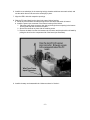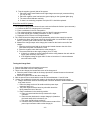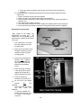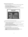
1
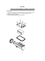
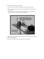
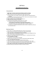
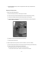
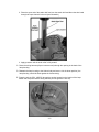
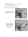
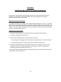
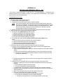
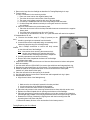
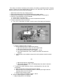
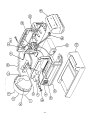
TABLE OF CONTENTS
Preface ..............................................................................................…….. 2
Troubleshooting Procedure ........................................................……….. 3
General Notes ....................................................................................……. 4
Section I, Litebox Housing Disassembly/Assembly Procedures ......... 5
Section II, Testing/Replacing the Lamp .................................................. 8
Section III, Testing the Litebox Battery .................................................. 9
Section IV, Testing/Replacing the Switch ...........................................… 10
Section V, Testing/Replacing the Wiring Harness ................................. 11
Section VI, Testing/Repairing the Printed Circuit .................................. 15
Section VII, Testing and Repairing the Charging System ..................... 18
Appendix I , Identifying and Testing the Power Failure Model ............. 23
Appendix II , Litebox Replacement Parts and Diagram ...................... 24
Appendix III , Testing and Repairing the SL - 40X ................................. 25
Appendix IV , SL- 40X Replacement Parts and Diagram ……………..… 30
-1-
LITEBOX SERVICE MANUAL
PREFACE
The purpose of this manual is to provide the information needed to service the Streamlight
Litebox flashlight system.
This manual is dated (see front cover). Additions, deletions and changes to this manual will
display a later date.
A set of tools including a Philips screwdriver, pliers, and a multimeter are required to service
the Litebox.
Additional tools which are available:
(1) Switch boot tool, Streamlight P/N 450074
(2) Strain relief tool, Streamlight P/N 450075
Lamp may be changed without special tools.
For additional information and/or assistance contact:
STREAMLIGHT, INC.
Repair Department
1030 West Germantown Pike
Norristown, Pa. 19403
Phone (610) 631-0600
Phone (800) 523-7488
FAX (610) 631-0712
7:00 a.m.-5:00 p.m. EST
-2-
GENERAL NOTES
Troubleshooting Note
A troubleshooting diagram is provided (page 3) to help enable a repair technician to isolate and
repair electrical problems which can arise. The diagram describes a condition and suggests the
underlying cause. Repair procedures are provided in the chapters indicated in the solution
blocks. The troubleshooting procedure does not attempt to isolate individual components.
Instead it suggests replacement of modules or assemblies such as the printed circuit board, the
battery, the switch, etc. Occasionally problems may arise which are not included in the
troubleshooting procedure. In these cases a thorough physical inspection may reveal a broken
wire, cracked or damaged circuit board, or some other mechanical damage which results in an
apparent electrical problem. If the Litebox can be turned “on” and “off “ and the problem is still
elusive the printed circuit board may be malfunctioning. The printed circuit board can be replaced
as a module (see Section IV). If the problem remains elusive the Litebox and all of its available
components (including the mounting rack and plug-in wall charger) should be returned to
Streamlight for factory service.
The Red and Green Charge Indicators
The Litebox is equipped with two LED’s which light to indicate the mode which the
charging circuit is in. The red LED indicates that the battery is being charged. The
green LED indicates that the charging cycle is complete and the battery is at
maximum capacity.
The LED’s can warn of malfunctions within the charging circuitry. The red LED
should turn “off” completely twenty-four (24) hours or less after the charge cycle is
initiated and the green LED should turn “on”. If the red LED remains lit for more than
24 hours the charging circuit must be tested and replaced or repaired as necessary
(see section VI).
Additional Information
Important Note : When mounting or repairing the charge rack Do Not Use anaerobic thread
locking compounds (Loc-tite, etc). Chemical reactions caused by the curing of these compounds
destroys the molded plastic and will void the factory warranty.
Caution : Adjustment of the controls on the printed circuit board within the Litebox should be
performed only within the guidelines established in this manual. Improper adjustment may result
in serious damage to the system and may cause physical injury. Damage caused by improper
settings may require extensive repair at the factory.
The plugs and sockets may be cleaned with contact cleaner (make sure it is plastic safe) to
minimize corrosion. Silicone grease may be used to improve contact and retard corrosion. Make
sure that the power is disconnected and lightly spread a small amount on each connector plug
pin.
-4-
SECTION I
LITEBOX HOUSING DISASSEMBLY/ASSEMBLY PROCEDURES
Disassembly
1.
2.
3.
4.
Use a Phillips screwdriver to remove the six screws from the bottom of the Litebox.
Separate the top and bottom halves of the housing by pulling them apart.
Remove the black rubber gasket.
Disconnect the battery leads and remove the battery.
-5-
Reassembly
1. Make sure that the battery wires are properly routed (see diagram).
a. Press each wire firmly into the proper slot.
Note : The battery wires must be properly seated and should not cross one another.
b. Lay the foam sheet over the wires before inserting the battery.
2. Place the battery onto the bottom housing.
a. The positive battery terminal must face toward the lamp holder (see diagram).
b. Use a pair of needle nose pliers to connect the leads to the battery terminals (red to positive;
black to negative). Note : The positive terminal is marked with a red patch and a “+” sign.
3. Fit the black rubber gasket onto the upper housing.
-6-
4. Align the bottom and top halves of the housing.
a. The charge connector on the bottom housing should face the rear of the Litebox.
b. Make sure that the charge connector wiring is routed through the center channel of the
bottom housing.
c. Remove the slack from the charge connector wiring by drawing any excess wire to the
component side of the printed circuit board (see illustration).
5. Place the top and bottom halves of the housing together and make sure that they mate fully
with the black rubber gasket.
6. Insert the six screws into the bottom and tighten them until they are snug.
-7–
SECTION II
TESTING/REPLACING THE LAMP
1. Remove the black rubber lamp ring from the lamp housing.
note : A flat blade tool can be used to help pry the black rubber ring from the housing.
2. Pull the lamp/reflector assembly from the lamp housing.
3. If the lamp is the sealed beam type disconnect the slip-on connectors from the lamp blades.
a. Test the bulb by placing a multimeter into the continuity position and place one lead on
each lamp contact (a beep indicates a good bulb).
b. Replace the bulb if necessary.
c. The wattage of the bulb is shown on the back of the lamp in the second printed data line.
1. Example “ 6V 8W 01-28-96 1720” - the 2nd group of characters (8W) indicates the
wattage (8 watts).
2. A clear lens is a spotlight pattern (“S“); a waffled lens is a flood pattern (“F”).
4. If the lamp is the new style with a plastic reflector and screw-in bulb(s) follow the
instructions below.
a. Test the bulb(s) by unscrewing the plastic threaded bulb socket from the plastic reflector.
1. Pull the old bulb straight out from the socket.
2. Use a multimeter in the continuity position and place a meter lead on
each bulb lead (a beep indicates a good bulb).
b. Bulb replacement
1. Replacement bulb information (voltage and wattage) is printed on a label located on the
back of the reflector assembly .
2. Replace the bulb by aligning the pins with the holes in the socket and seat the bulb
firmly.
3. Wipe off any fingerprints from the bulb with a tissue and alcohol.
4. Screw the socket back into the reflector assembly.
a. The socket can be fully seated in the flood reflector assembly.
b. The socket can be adjusted in the spot reflector assembly.
1. Turn the Litebox on and shine it on a wall approximately 10 feet away.
2. Adjust to the desired focus by screwing the socket inward towards the fully seated
position or outwards until the point where the socket O-ring starts to leave the
surrounding screw shell of the reflector. Note : The focus should be attained
somewhere between the two limits described (try 1/4 turn out from the fully seated
position).
5. Place the reflector assembly into the lamp housing.
a. Try to dress the wires away from one another.
b. The reflectors need to be aligned so that the key on the reflector fits into the recesses on
the lamp housing.
c. There are two key positions on the plastic reflector assembly which allow the flood pattern
to be adjusted to either a wide or a tall pattern.
6. Replace the black rubber lamp ring.
note : A flat blade tool can be used to help pry the black rubber ring onto the lamp housing.
-8-
SECTION III
TESTING THE LITEBOX BATTERY
1. Disassemble the Litebox as shown in Section I.
2. Remove the battery from the Litebox.
a. Carefully disconnect the battery leads.
b. Slowly pull the battery from the Litebox housing and remove the foam pad.
3. Charge the battery to full capacity in a known good Litebox system.
4. Operate the battery in a known good Litebox and note the run time.
a. Run time is the time from when the Litebox is turned on to the point where it becomes
no longer usable.
b. Nominal run times are 8 hours for the 8 watt bulb and 3.5 hours for the 20 watt bulb.
Lamp Option
8 watt spot/flood
20 watt spot/flood
Run Time
8.00 hrs.
3.50 hrs.
Charge Time (AC)
24.0 hrs.
24.0 hrs.
Charge Time (DC)
15-24 hrs.
15-24 hrs.
c. Normal intensity and short run time is usually an indication that a battery is suffering
from sulfation.
d. Low intensity and normal run time is usually an indication that a battery has one or
more shorted cells.
e. Batteries which exhibit signs of sulfation or shorted cells should be replaced.
5. Install the battery and reassemble the Litebox as shown in Section I.
-9-
SECTION lV
TESTING/REPLACING THE SWITCH
Testing the Switch
1. Disassemble the Litebox and disconnect the battery as shown in Section I.
Note : Make sure that the battery leads are disconnected from the battery.
2. Slide the printed circuit board outward from the upper Litebox housing.
a. Slide the board out far enough to access the solder pads where the switch leads are
connected.
b. Use care to avoid bending the leads of the LED’s mounted on the underside of the board.
3. Place a multimeter into the continuity position.
4. Place one lead on each of the solder pads marked “S 1”.
5. Depress the switch 8 times (4 on/off cycles).
6. The multimeter should indicate continuity for the 4 “on” cycles.
a. If continuity is indicated as above the switch is functional.
1. Slide the printed circuit board back into the upper Litebox housing.
(note: Make sure that the LED’s are aligned with their respective openings).
2. Reinstall the battery and reassemble the Litebox as shown in Section I.
b. If continuity is not indicated as described the switch needs to be replaced according to
the instructions below.
Replacing the Switch
1. If the Litebox is not already disassembled refer to Section I for instructions.
2. Slide the printed circuit board out of the slots in the upper Litebox housing.
(note: Use caution to avoid bending the LED’s out of place).
3. Use the switch boot tool (P/N 450074) to remove the switch boot and integrated lock ring.
(note: The lock ring is an integral part of the boot).
4. Desolder the switch leads from the solder pads marked “S 1” and discard the old switch.
5. Obtain a new switch (P/N 400157).
a. Cut the leads to 4” in length.
b. Strip and tin 1/4” from the end of each lead.
6. Solder the leads of the switch to the printed circuit board at the solder pads marked
“S 1”. (note: Either lead to either pad.)
7. Install the new switch in the opening in the upper Litebox housing.
8. Use the switch boot tool to secure the switch boot and integrated lock ring in place.
(note: Do not overtighten the switchboot as it may prevent the switch from turning "on".)
9. Slide the printed circuit board back into its slots in the upper Litebox housing.
(note: Make sure that the LED’s are aligned with their respective openings.)
10. Install the battery and reassemble the Litebox as shown in Section I.
- 10 -
SECTION V
TESTING/REPLACING THE WIRING HARNESS
Testing the Wiring Harness
1. Disassemble the Litebox as shown in Section I.
2. Disconnect and remove the battery.
3. Remove the lamp ring, reflector, and lamp from the lamp head as shown in Section II.
A . Inspect and test the wiring harness between the Litebox pc board and the lamp housing.
1. If the wiring is frayed or damaged it should be replaced.
2. Test the lamp wires for continuity.
a. Place a multimeter in the continuity position.
b. Place one of the meter leads on any of the lamp lead connectors located at the lamp
head.
1. If the leads are color-coded place the other meter lead onto the corresponding
PC board solder pad position (see illustration).
a. The meter should indicate continuity.
b. Repeat the above procedure for each lamp lead.
B. If the test of the leads does not indicate continuity or if the leads are black and
made from lamp cord the wiring harness will need to be replaced. A head
upgrade kit is available P/N: 450104(orange), 450105(beige), or 450107 (yellow).
- 11 -
C. If the wiring harness does not need to be replaced the Litebox may be reassembled as
shown in Section I.
Replacing The Wiring Harness
1. Remove the existing wiring harness.
A . Remove the lamp ring, reflector, and lamp from the Litebox.
B. Loosen and remove the swivel assembly which connects the lamp head to the body.
C. Cut the wire tie fastener which secures the wiring harness to the lamp head.
D. Use wire cutters to cut the wiring harness strain relief base where it passes through the
Litebox housing (see illustration).
E. Desolder and remove the lamp leads from the PC board
F. Discard the old wiring harness.
2. Install the replacement wiring harness (2 wire P/N : 450053 or 3 wire P/N : 450054).
A . Route the wiring harness (slip-on connectors first) through the opening in the Litebox body.
B. Place the strain relief in the opening in the Litebox body.
(note: Apply soapy water to the strain relief to provide lubrication.)
1. Use the strain relief tool (P/N : 450075) to seat the strain relief in place.
- 12 –
2. Place the open end of the strain relief tool over the strain relief and direct the wire leads
through the open channel in the tool (see illustration).
3. Apply pressure until the strain relief is fully seated.
C. Route the wiring harness (slip-on connector end) through the opening in the back of the
lamp housing.
D. Reattach the lamp housing to the Litebox body and secure it in the down position ( the
lamp housing should be flush against the Litebox body).
E. Place the wire tie (P/N : 450073) through the anchor located on the interior of the lamp
holder and wrap it around the wiring harness (do not tighten the wire tie).
- 13 –
F. Draw the wiring harness away from the eyelet to remove slack.
G. Maintain tension on the wiring harness and draw the wire tie snug to secure the harness in
place (trim the excess portion of the wire tie).
H. Solder the lamp leads to the PC board (see Section VI).
I. Replace the lamp, reflector and lamp ring.
J. Reassemble the Litebox as shown in Section I.
- 14 -
SECTION VI
TESTING/REPLACING THE PRINTED CIRCUIT BOARD
Testing the Printed Circuit Board
1. Disassemble the Litebox as shown in Section I.
2. It is important to determine that the power input charging connector is functioning properly.
Refer to Section VIl, Testing the Litebox Charge Connector. Do not reassemble the
Litebox; follow the testing instructions below.
3. Disconnect both battery leads and remove the battery.
Caution : The battery must not be connected to the leads.
4. Make sure that the switch has been checked according to the instructions in Section IV.
5. Make sure that the wiring harness has been checked according to the instructions in
Section V.
6. Connect the Litebox to a known good wall charger.
A . If the green LED is lighted and the red LED is off follow the test procedures below.
Set the multimeter to the DC volts position.
1. Place the positive meter lead on the red battery lead.
2. Place the negative meter lead on the black battery lead.
3. The meter should read between 7.1 and 7.4 volts.
a. The green LED should be on
b. The red LED should be off.
4. Keep the multimeter connected to the battery leads.
a. Place a 15 ohm/10 watt resistor across the battery leads.
b. The multimeter should read between 6.65 and 6.95 volts.
c. The green LED should be off.
d. The red LED should be on.
e. If the PC board performs as outlined in the steps above it
is functional (reassemble the Litebox as shown in Section I).
f. If the PC board did not perform satisfactorily it should be replaced.
B. If the red LED is lighted, both LED's are lighted, or neither LED is lighted, the circuit
board should be replaced.
Replacing the Printed Circuit Board
1. Disassemble the Litebox as shown in Section I.
2. Remove the input power connector from the
bottom Litebox housing.
a. Remove the screw holding the connector.
b. Pry the connector upward and away from
the mounting hole in the housing (see
illustration).
- 15 -
3. Remove the switch.
a. Remove the switch boot and integrated lock ring with the switch boot tool.
b. Slide the switch free from its mounting hole.
4. Pull the PC board out of its slots in the housing.
5. Desolder the lamp leads and discard the old PC board and switch.
6. Desolder the lamp leads which are included on the new PC board.
a. For Standard and Power Failure model
Liteboxes solder the existing lamp leads to the
new PC board at the pads marked “L 1” (see
illustration).
b. For Dual Filament and Dual Bulb model
Liteboxes solder the existing lamp
leads to the new PC board as follows:
1. Solder the green and white lamp
leads to the solder pads marked
"L 1".
2. Solder the black lamp lead to the
solder pad marked "L 2".
- 16 -
6. Install the new switch(es) in the mounting hole(s); thread a switchboot onto each switch, and
use the switch boot tool to secure the switch(es) in place.
7. Align the LED’s with their respective openings.
8. Slide the PC board back into the slots in the upper Litebox housing.
a. Route any excess switch and lamp wiring into the well where the switch is located.
b. Install the power input connector in the bottom housing of the Litebox .
1 . Place the power input connector (slot side up) through the rear opening in the bottom
housing and snap the connector into place.
2. Secure the connector in place with the retaining screw.
3. Remove the slack from the wire between the connector and the printed circuit board by
pulling the wire from the component side of the board (see illustration).
9. Install the battery and reassemble the Litebox as shown in Section I.
- 17 –
SECTION VII
TESTING/REPAIRING THE CHARGING SYSTEM
The Litebox charging rack is available in two configurations. Both systems have a two pin
connector located at the rear of the charge rack which provides charging power to the Litebox.
The difference between the two systems is the way which external power is delivered to the
charge rack. The Litebox Vehicle Mount System has a 12VDC power cord which is permanently
attached to the charge rack. The Litebox Standard System rack has a power input connector
which is mounted on the side of the rack housing. Systems which use a charge rack must be
tested with the Litebox removed from the rack.
Testing For Input Power From The AC Wall Charger
1. The AC wall charger can be tested by simply measuring its output
voltage.
2. Make sure that the wall charger is plugged into a functioning 120Volt
AC outlet.
3. Place a multimeter in the DC volts position.
4. With the charge connector facing towards you the black key should
be located at the top of the connector (see illustration).
a. Place the positive lead from the meter onto the left pin of the
connector.
b. Place the negative meter lead on the right pin.
5. The meter should give a reading between 13 and 22 volts and
there should be no indication of reversed polarity.
6. If the voltage or polarity is wrong replace the charger.
7. Do not attempt to repair the AC charger.
Testing For DC Input Power
DC - 1 System (cigarette plug)
1.
2.
3.
4.
Connect the DC-1 charger plug to its power source (power point, cigarette lighter outlet, etc.).
Place a multimeter into the DC Volts position.
The voltage should be measured as directed in step 4 above (AC testing).
The meter reading should reflect the vehicle’s supply voltage and should be between 12 and
15 Volts DC.
A . If there is no reading the system needs to be checked.
1. Place the multimeter into the continuity test position and place the positive lead onto the
left charge connector pin (with the connector facing you, key on top).
2. Place the negative meter lead onto the tip of the cigarette lighter plug.
3. The meter should beep and/or indicate that the circuit is complete.
a. If the circuit is not complete then the fuse may have blown or the wire may be broken.
b. Replace the fuse by unscrewing the end of the cigarette lighter plug.
c. Replace the fuse with a 20mm X 5 mm fuse (2 amp slow-blow, 2 amp fast-blow, or
5 amp fast blow).
B. Test again as in steps 2,3,4 above.
1. If the circuit is still not complete disassemble the cigarette lighter plug and inspect the
connections.
2. Repair any loose or broken connections.
- 18 -
C. Test the negative (ground) side of the system.
1. Place the positive meter lead onto the right charge connector pin (connector facing
you, key on top).
2. Place the negative meter lead onto the ground spring on the cigarette lighter plug.
3. The meter should indicate continuity.
4. If there is no continuity (complete circuit) the DC-1 should be replaced.
Direct Wire and DC-2 Systems
1. DC-2 system testing (system does not have a rack and utilizes the Litebox input connector).
a. Connect the DC-2 to a known good 12 volt source.
b. Place a multimeter in the DC volts position.
c. The voltage should be measured as in step 4 of the AC input test procedure.
d. The meter should give a reading of between 12 and 15 volts DC.
e. Replace the DC-2 if there is no voltage detected.
2. The 12VDC direct wire charge rack has a permanently wired cord to supply input power.
a. If possible the direct wire charger should be checked while it is connected to its power
source ( a known good 12VDC source is also suitable).
b. Measure the charger output at the charge pins located on the interior rear wall of the
charger.
1. Place the positive meter lead on the charge pin located closest to the side of the
rack where the power cord enters the rack.
2. Place the negative meter lead onto the other charge pin.
3. The meter should show the supply voltage (12 to 15 volts).
a. If there is no voltage or reverse voltage check the wiring between the rack and the
supply (also check any in-line fuse).
b. If the supplied voltage is higher than 15 volts or lower than 12 volts an alternate
source should be used.
Testing the Charge Rack
1. Connect the charge rack to its power input source.
2. Place a multimeter in the DC volts position.
3. There are two charge pins located at the rear of the charge rack.
a. Place the positive meter lead on the charge pin which is located closest to the external
power input connector.
b. Place the negative lead on the other charge pin.
4. With the power source connected the meter should read between 11 and 22 volts.
5. If there is no reading the charge rack needs to be checked for internal wiring integrity.
A . Charge racks which utilize an external power connector should be disconnected from
their power source.
1. Place the charge rack on a flat surface with the power input
connector facing you.
2. The power input connector has a key slot which should be
facing toward the rear of the rack.
3. Place a multimeter in the continuity position.
a. Place one meter lead into the top contact of the input
connector.`
b. Place the other lead onto the output charge pin (located on
the interior wall) which is closest to you.
c. The meter should indicate continuity.
d. Follow the same procedure to test the bottom contact of the
power input connector and the other charge pin.
- 19 –
e. If the meter does not indicate continuity the interior wiring harness should be
replaced.
B. Charge racks with permanently wired input power should be disconnected from their
input source.
1. Place a multimeter into the continuity position.
2. Place one lead on the positive power input lead (red stripe).
3. Place the other lead onto the output charge pin (located on the interior wall) which is
closest to you.
4. The meter should indicate continuity.
5. Follow the same procedure to test the negative lead (black) and the other charge pin.
6. If the meter does not indicate continuity the wiring harness will need to be replaced.
Repairing The Charge Rack
Both versions of the charge rack
disassemble the same way. The
charge rack is held together by two
push retainers located on the bottom
of the rack.
1. Use a pointed tool to remove
the push retainers from their
mounting posts.
2. Insert the tool (as shown in the
illustration) and pry the push
retainers up and off of their
mounting posts.
3. Remove the existing wiring
harness. Note : Replace
the direct wire model with
P/N: 450031 and use P/N:
450029 for the standard
model.
4. Place the charge connector
in the opening in the upper
charge rack housing and
slide the assembly in place.
5. Place the charge pin
assembly in the notches on
the rear wall of the charge
pin
opening.
Note:
The
assembly
is keyed and will only install
one
way.
When
the
assembly
is properly installed the
positive (white striped) lead
is closest to the charge
connector.
- 20 -
Testing the Litebox Charge Connector
1. The Litebox charge connector should be tested to make sure that it is functional.
2. Disassemble the Litebox and remove the battery as shown in Section I.
3. Test the connector and wiring by one of the following methods.
A . If an AC wall transformer is available the output connector from the transformer can be
connected directly to the input connector of the Litebox.
1. Use a multimeter to check the input voltage.
2. Pull the circuit board straight up and out of the slots in the upper housing.
Note : Make sure that the PC board is on a non-conductive surface whenever power is
applied to it.
3. Place the multimeter into the DC volts position.
a. Place the positive lead onto the soldered connection where the wire is connected to
the
board (this location is marked with a “ + “).
b. Place the negative lead onto the soldered connection marked “ - ”.
c. The meter should read between 13 and 22 volts and a “ - ” should not precede the
reading.
B. If an AC wall transformer is not available the charging connector can be checked by placing
the multimeter into the continuity position.
1. Test the positive input.
a. Hold the input connector so that the keyed slot is facing upwards.
b. Place the red lead from the multimeter into the right socket (located inside the
charging input connector).
c. Place the black lead onto the solder pad marked “+” on the printed circuit board.
d. The meter should beep and indicate continuity.
2. Check the ground input.
a. Place the positive meter lead into the left socket and place the negative meter lead onto
the solder pad marked “ - “ on the printed circuit board.
b. The meter should beep and indicate continuity.
- 21 -
Replacing the Litebox Charging Connector
A . If continuity is not indicated or no voltage is detected (AC charger test) the lantern charging
harness will need to be replaced.
1. Pull the printed circuit board straight up and out of the slots in the top housing.
2. Remove the input connector retaining screw.
3. Insert a screwdriver under the connector where the wire is attached to it.
4. Pry the rear of the connector upwards approximately 1/4”.
5. Push on the front of the connector where it contacts the housing until the connector slides
free from its mounting hole.
B. Install the new lantern charging harness as shown below.
1. The wire from the input connector passes through a hole located in the printed circuit
board.
2. Unsolder the two leads of the charging harness from the rear of the PC board.
a. Clean the mounting holes thoroughly.
b. Discard the old charging harness.
3. Route the wire of the new charging harness (P/N : 450028) through the hole on the back of
the PC board (the side without the components).
4. Solder the white striped (positive) lead to the solder pad marked “ + “ on the PC board.
5. Solder the black (negative) lead to the solder pad marked “ - ”.
6. Place the input connector (slot side up) through the rear opening on the bottom housing
and
snap the connector into place.
7. Secure the input connector with the connector retaining screw.
8. Slide the PC board into the slots in the upper housing until it seats.
Note : Make sure to align the LED’s with the openings in the housing.
9. Route the input connector wire through the open grid in the bottom of the housing.
10. Install the battery and reassemble the Litebox as shown in Section I.
- 22 -
APPENDIX I
IDENTIFYING AND TESTING THE POWER FAILURE MODEL
Power Failure model Liteboxes are essentially the same as conventional Liteboxes with the
exception of the PC board. Follow the standard instructions contained in this manual to
identify and test the Power Failure model.
Identifying The Power Failure Model
The label located above the LED’s on the Litebox indicates what type of unit it is. The power
failure version is marked with the words “power failure” above the serial number on the label. The
power failure model Litebox printed circuit board is different from that of the non-power failure
Litebox. The power failure circuit board has most component positions filled (some examples
are: Q5, C4, Q4, CR10 and R14-R17).
Testing a Power Failure Litebox
1. First remove the Litebox from its charging rack and verify that the lamp is working.
2. If the lamp works switch the Litebox off.
3. Connect a wall charger directly (no charge rack) to the Litebox.
a. If the charger is not plugged into a wall outlet the Litebox should turn on with full intensity.
b. Plug the wall charger into a working wall outlet; the Litebox should turn off.
4. An optional method of testing the power failure Litebox is to use a piece of wire (or needle
nose pliers) to short the contacts on the power input connector. When the contacts are
shorted the power failure Litebox should turn on.
If the Power Failure model fails to perform as indicated above; the printed circuit board will need
to be replaced. Refer to Section IV.
- 23 -
APPENDIX III
TESTING AND REPAIRING THE SL - 40X
This section includes information to repair the SL - 40 series flashlights. A multimeter and
Phillips screwdriver will be needed to perform most repairs and troubleshooting. Some repairs
may require the use of a soldering iron.
Testing/Replacing the Lamp
1. The lamp is held in place by the lamp ring.
a. Hold the body of the flashlight firmly.
b. Press down on the lamp ring and rotate it counter clockwise.
NOTE : Use care and attempt to avoid stressing the lamp housing where it connects to
the body of the flashlight. An alternate method of securing the lamp housing is to
move the lamp housing to a position 90 degrees from the flashlight body. Place
the back of the lamp housing on a sturdy work bench or desk top to provide
leverage while the lamp ring is being turned.
c. Remove the lamp from the lamp housing and slip the wire leads from the bulb leads.
2. Test the lamp while it is disconnected from the flashlight
a. If the lamp is the sealed beam type test as below.
1. Place a multimeter into the continuity position.
2. Place the red lead on one of the lamp contacts
3. Place the black lead on the other lamp contact.
4. The meter should beep and indicate continuity.
b. If the lamp is the new style with a plastic reflector and screw-in bulb test as
below.
1. Test the bulb by using a multimeter in the continuity position.
2. Place the red meter lead on one of the bulb leads.
3. Place the black meter lead on the other bulb lead.
4. The meter should beep and indicate continuity.
3. If the meter does not indicate continuity the bulb will need to be replaced.
a. If the SL-40 was equipped with a sealed beam bulb it will need to be upgraded with
the PAR-36 Lamp Retrofit Kit P/N : 40107.
1. The kit contains 3 lamp spacers which are required to support the new plastic reflector
system.
a. Place the lamp spacers (beveled edge down) into the slots provided in the head.
b. The spacers' support surface should be located 1/8" below the edge of the lamp
housing (see illustration).
- 25 -
2. The new black lamp ring will be used at the end of this procedure to secure reflector
and bulb in place.
b. When the SL-40 is equipped with the new system follow the instructions below.
1. Replace the bulb(s) by unscrewing the plastic threaded bulb socket from the plastic
housing.
a. Pull the old bulb straight out from the socket.
b. The bulb is labeled with voltage and wattage.
c. Replacement bulb information is printed on the back of the reflector assembly.
2. Replace the bulb by aligning the pins of the new bulb with the holes in the socket and
seat the bulb firmly.
3. Wipe off any fingerprints from the bulb with a tissue and alcohol.
4. Screw the socket back into the reflector assembly.
a. The socket can be fully seated in the flood reflector assembly.
b. The socket can be adjusted in the spot reflector assembly.
1. Turn the SL-40 on and shine it on a wall approximately 10 feet away.
2. Adjust to the desired focus by screwing the socket in to the fully seated position
or outwards until the point where the socket O-ring starts to leave the
surrounding screw shell of the reflector. Note : The focus should be attained
somewhere between the two limits described (try 1/4 turn out from the fully
seated position).
5. Place the reflector in the lamp housing and secure it in place with the lamp ring.
Battery Replacement and Testing
1. Test the battery as instructed in Section III of this manual.
2. Remove the battery from the flashlight.
a. Use a Phillips screwdriver to remove the four screws located on the rear cover of the
flashlight.
b. Remove the rear cover.
c. Slowly slide the battery out of the body of the flashlight.
Note : Use care when removing the battery so that the battery terminals and wiring
harness do not become stressed.
d. Remove the protective tape which covers the battery terminals.
e. Slide the battery leads from the battery terminals.
3. Replace the battery in the flashlight.
a. Connect the red battery lead to the positive battery terminal.
b. Connect the black battery lead to the negative battery terminal.
Note : Always use a fusible link (P/N: 400307)
between the negative lead and the
negative battery terminal.
Note : It is very important that proper polarity
is observed. Reversed wiring may
cause permanent damage to the
SL - 40.
c. Tape the connections securely in place with
3/4” strapping tape.
d. Place the positive end of the battery into the
rear opening of the flashlight and slowly guide
it into the body until its seats in place.
1. As the battery is sliding in take the slack
out of the positive lead and guide it into the
channel in the side of the SL - 40. A wire
hook is helpful (see illustration).
- 26 –
2. A small loop of the black (negative) lead should remain outside of the rear of the
housing.
3. When the battery is seated tuck the extra loop of wire into the slot between the battery
and the flashlight housing.
e. Place the rear cover on the flashlight and secure it in place with the four Phillips screws.
Note : Be careful not to overtighten the screws as they could strip their plastic anchors.
Testing/Replacing the Switch
If the battery and lamp are in proper working order but the flashlight still fails to operate the
switch may be malfunctioning.
1. Disconnect the SL-40 from any charging source.
2. Remove the battery and rear cover as described in the battery section above.
3. Remove the lamp from the flashlight as described in Testing/Replacing the Lamp
4. Test the switch.
a. Place a multimeter in the continuity position.
1. Place one meter lead on the negative battery lead.
2. Touch the other meter lead to either of the lamp leads.
3. The meter must indicate continuity with one of the lamp leads.
4. If continuity is established with one of the lamp leads put that lead aside.
5. If neither lamp lead indicates continuity the wiring will need to be checked
(see 6 below).
b. Place one meter lead on the positive battery lead.
1. Place the other meter lead on the lamp lead which was not connected to the negative
battery lead.
2. Cycle the switch at least 8 times (four on/off cycles).
3. If continuity is not indicated in all four “on” cycles the switch will need to be replaced.
5. Disassemble the SL-40.
a. Remove the shoulder strap D - Rings (if present) on the
carry
handle by opening them outwards from the handle.
b. Loosen and remove the adjustable wing nut assembly which
fastens the lamp housing to the flashlight body.
c. Use a Phillips screwdriver to remove the body screws
located
on the side and foot of the flashlight.
Note : Use caution when removing the screws as their
anchor nuts (located on the opposite side) will be
freed from their mountings and could be misplaced.
d. Carefully separate the two halves of the body.
e. Remove the rubber footpads at the bottom of the flashlight
and place them aside.
6. Inspect the wires to make sure that none of them are disconnected or broken and replace
them as necessary.
7. Use the switch boot tool (P/N 450074) to remove the switchboot and integrated lock ring.
8. Desolder the switch leads from the circuit board. (The replacement switch is P/N 400157)
9. Solder the leads of the replacement switch to the circuit board at the solder pads
marked “sw” (either lead to either pad).
10. Place the new switch into the opening in the handle.
11. Use the switch boot tool to secure the switch boot and integrated lock ring in place.
12. Reassemble the SL-40.
a. Align the two halves of the flashlight body.
- 27 1. Make sure the circuit board is inserted in the slots provided.
2. Join the two halves of the flashlight body together.
3. Check to make sure that there are no pinched wires.
b. Place the body screws in their mounting holes and secure them with their anchor nuts.
c. Replace the rubber footpads in their openings at the bottom of the flashlight.
d. Place the lamp housing mounting screw and wing nut into the mounting hole located on
the flashlight body forward of the carrying handle and secure the lamp housing in position.
e. Reattach the D-Rings (if desired) by aligning them with their mounting holes and
squeezing them into place with pliers.
f. Reinstall the battery and rear cover as described in the battery section.
Testing/Repairing the Circuit Board
If the lamp is functional, the battery tests properly, the switch is operational and the charging
system is working, but the flashlight fails to operate or the LED fails to light there may be a
problem with the circuit board inside the flashlight.
1.
2.
3.
4.
Disconnect the S-40 from any charging source.
Remove the battery and rear cover as described in the battery section.
Disassemble the flashlight as described in the testing/replacing the switch (step 5).
Perform a visual inspection of the circuit board.
a. Look for broken or pinched wires.
b. Look for broken connections where the wires are soldered to the board.
5. Test the components of the circuit board.
A . The 5 ohm, 5 watt resistor is located near the center of the board (see illustration).
1. Check the resistor to see if it is open.
a. Use a multimeter set to the lowest ohms position.
1. Place the black lead on either one of the resistor leads.
2. Place the red lead on the other resistor lead.
3. The meter should read close to zero (approx. 5 ohms).
4. If the meter indicates an “open” condition the resistor will need to be
replaced.
b. If a multimeter is not available a jumper wire can be placed across the resistor
leads.
- 28 –
1. Apply charge power to the flashlight .
2. If the charge indicating LED on the flashlight lights the resistor is bad and
needs to be replaced.
2. To replace the resistor desolder it from the mounting pads on the rear of the
circuit board.
a. Make sure that the mounting holes are free of debris.
b. Bend the leads of the replacement resistor so that they are aligned with the
mounting holes on the circuit board.
c. Solder the new resistor in place.
d. Test the resistor as described in step A 1 above.
B. The 3 pin voltage regulator is marked “7905”.
1. Apply charge power to the flashlight.
2. Place a multimeter in the DC volts position.
a. Place the red (positive) lead onto pin 1 of the regulator.
b. Place the black (negative) lead onto pin 3 of the regulator.
c. The multimeter should give a reading of 5 volts (10% tolerance allowed).
3. To replace the voltage regulator desolder it from the solder pads on the rear
of the circuit board.
a. Make sure that the mounting holes are free of debris.
b. When the voltage regulator is properly oriented (label side toward you) pin # 1
is the pin on the left.
c. Align the leads of the new voltage regulator with the holes in the circuit board.
d. Solder the three pins of the voltage regulator in place.
e. Test the voltage regulator as described in B 1,2 above.
Note: If the voltage regulator still fails to perform reassemble the light as below
and send it to:
Streamlight, Inc.
Repair Department
1030 W. Germantown Pike
Norristown, Pa. 19403
Testing/Repairing the Charger System
See Section VI of the SL-45 Litebox manual (p. 12) for charger testing and repair information.
- 29 -
SL - 40 REPLACEMENT PARTS
ITEM
1
2
QTY PART NO.
1
1
30
3
4
3
1
5
6
2
1
7
8
9
1
1
1
10
1
11
1
12
1
13
14
15
1
1
1
40107
40117
45908
45911
45910
45913
40114
400105
400105-1
202027
4051
4052
400130-1
400157
400258
400258-1
400254
400256
400255
400257
400174
400126
400126-1
400123
45937
400167
KIT, PAR 36 LAMP RETROFIT
(LAMP RING & SPACERS)
KIT, PAR 36 LAMP RETROFIT, BEIGE
LAMP, 8W FLOOD
LAMP, 8W SPOT
LAMP, 20W FLOOD
LAMP, 20W SPOT
NEOPRENE SPACER (LAMP)
LAMP HOUSING, ORANGE
LAMP HOUSING, BEIGE
STRAIN RELIEF
SWIVEL HEAD ATT- ORANGE
SWIVEL HEAD ATT.- BEIGE
SWITCH BOOT
SWITCH W/BOOT
REAR COVER,ORANGE (W/FOOT)
REAR COVER,BIEGE (W/FOOT)
BODY R.H. - ORANGE
BODY R.H. - BEIGE
BODY L.H. - ORANGE
BODY L.H. - BEIGE
DOOR, SOLID - ORANGE
DOOR, SLIDING - ORANGE
DOOR, SLIDING - BEIGE
NEOPRENE FOOT
BATTERY
COILED CORD ASSY.
ITEM
QTY
PART NO.
DESCRIPTION
16
1
400176
400175
900079
400241
400242
45070
45071
40072
40073
PLUG ASSY.- 4 PIN P.F.
PLUG ASSY - 2 PIN STANDARD
L.E.D.
P.C.B. ASSY.- STANDARD
P.C.B. ASSY. - POWER FAILURE
RACK ASSY - STANDARD, ORG
RACK ASSY-DIRECT WIRE, ORG
RACK ASSY-P.F., ORANGE
RACK ASSY - P.F. BEIGE
17
18
1
1
19
1
NOT SHOWN
40232
400262
400267
400266
400307
400179
SHOULDER STRAP (W/D-RINGS)
D-RINGS, SHOULDER STRAP
SCREW PACKET,(REAR COVER)
SCREW PACKET, BODY
FUSIBLE LINK ASSY
KIT, 2-PIN PLUG (INCLUDES
PARTS FOR RACK AND LIGHT)
CHARGERS
22311
21725
22051
120V AC, STANDARD
230V AC, STANDARD
12V DC-1, W/LIGHTER ADAPTER
MISC. RACK
PARTS
400170
40163
STRAIN RELIEF (DIRECT WIRE)
LOCK, KEYED DIFFERENTLY
(INSTALLED)
LOCK, KEYED ALIKE
(INSTALLED)
40164
The lead acid battery in this product is recyclable. At the end of its useful life, under various state laws,
it may be illegal to dispose of this battery in the municipal solid waste stream. Check with your local solid
waste officials for details in your area for recycling options or proper disposal.
Pb
- 31 -