1
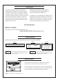
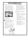
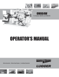
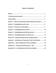
ONL673L4
For Model: NL673L4 and NL673L4E
OPERATOR’S MANUAL
Marine Generators | Marine Diesel Engines | Land-Based Generators
ULTRA LOW
SULFUR FUEL
ONLY
RE529956
As of January 2011, U.S. EPA regulations require the
application of a permanently applied label near the fuel tank
fill port for diesel driven equipment. This label is to state:
ULTRA LOW SULFUR FUEL ONLY
Northern Lights is providing this label for application to the
fuel inlet of the fuel supply tank for each engine or generator
set. This is to be applied by the installer of the engine or gen
set, or by the manufacturer of the equipment that the engine
or gen set is installed in. The location of the label must be
in clear site of personnel that refill the supply tank.
— CALIFORNIA —
Proposition 65 Warning:
Diesel engine exhaust and some of its constituents are known to the State of California to cause
cancer, birth defects, and other reproductive harm.
Northern Lights
4420 14th Avenue N.W.
Seattle, WA 98107
Tel: (206) 789-3880
Fax: (206) 782-5455
Copyright ©2013 Northern Lights, Inc.
All rights reserved. Northern Lights™, and
the Northern Lights logo are trademarks of
Northern Lights, Inc.
Printed in U.S.A.
PART NO.: ONL673L4 11/13
OPERATOR'S MANUAL
for Model
NL673L4 and NL673L4E
Read this operator's manual thoroughly before starting to operate your equipment.
This manual contains information you will need to run and service your new unit.
Table of Contents
SERVICING
Lubrication - General........................................ 15
Checking Oil..................................................... 16
Oil Changes...................................................... 16
Changing Oil Filter........................................... 16
Air Filter........................................................... 17
V-Belts.............................................................. 17
Valve Clearances............................................... 17
Fuels - General.................................................. 18
Fuel Filters........................................................ 18
Bleeding the Fuel System................................. 19
Injector Service......................................... 20 - 21
Injection Pump.................................................. 21
Cooling System - General................................. 21
Cooling System Flushing.................................. 22
Clean Radiator.................................................. 22
Electrical System - General.............................. 22
Glow Plugs........................................................ 23
Booster Batteries............................................... 23
Battery Care...................................................... 23
Winterizing / Out-of-Service............................ 23
Generator End........................................... 24 - 27
INTRODUCTION .....................................................2
Models Included..................................................2
Model Numbers...................................................2
Serial Numbers....................................................2
WARRANTY.............................................................3
SAFETY RULES................................................3 - 7
LOCK OUT / TAG OUT PROCEDURES.............8
COMPONENT LOCATIONS
Industrial Generator.......................................... 10
CONTROL PANEL
S-1B Control Panel............................................11
OPERATING PROCEDURES
Break-in Period................................................. 12
Before Starting.................................................. 12
Starting.............................................................. 12
Operating.......................................................... 12
Stopping............................................................ 12
Shutdowns and Alarms..................................... 13
Spare Parts........................................................ 13
TROUBLESHOOTING
Electrical........................................................... 28
Lamp Codes...................................................... 29
Engine....................................................... 30 - 32
SERVICING SCHEDULE CHART..................... 14
WIRING DIAGRAMS
AC Electrical............................................ 33 - 34
DC Electrical............................................ 35 - 40
Proprietary Information
This publication is the property of Northern Lights, Inc.
It may not be reproduced in whole or in part without the written permission of Northern Lights, Inc.
© Northern Lights, Inc. All rights reserved. Litho U.S.A. Publication number ONL673L4 11/13
ONL673L4 11/13
1
Introduction
Servicing of industrial generator sets presents
unique problems. In many cases these generators
are far from a repair facility. Generators cannot be
compared to the servicing of automobiles, trucks or
even farm equipment. Failures often occur in remote
areas far from competent assistance. Generators
can be taxed far more severely than auto or truck
engines; therefore, maintenance schedules must be
adhered to more strictly.
Failures begin with minor problems that are
overlooked and become amplified when not
corrected during routine maintenance.
As operator, it is your obligation to learn about your
equipment and its proper maintenance. This is not a
comprehensive technical service manual. Nor will it
make the reader into an expert mechanic. Its aim is
to aid you in maintaining your unit properly.
Unit Identification
MODELS INCLUDED
This manual covers the operating instructions for:
NL673L4 & NL673L4E industrial generator sets.
Model Numbers
Model numbers give the unit's application, block model, aspiration, and RPM:
NL
NL - Northern Lights industrial generator set
NL673L4
=
673
+
L, 4, E
Model number of engine block
Bore
Cylinders
67 mm
3
Northern Lights industrial generator set with a 673
engine, TF-276D series generator end, AVR, and
Tier IV compliant.
NL673L4E
=
L = Designates new
+ series of generator set
4 = Tier IV compliant
E = Electronic
Northern Lights industrial generator set with a
673 engine, TF-276D series generator end, AVR,
Electronic, and Tier IV compliant.
Serial Numbers
Your set has three serial numbers: an engine number stamped
on the block, a generator plate, and a generator set plate.
Use the serial number on the generator set plate when ordering parts
or in correspondence. The generator set plate is found on the service
side of the generator and resembles the drawing in Figure 1.
Figure 1: Generator set serial number plate.
ONL673L4 11/13
2
Revised 7-10-13
Warranty
NOTE: If the warranty is to apply, the servicing
instructions outlined in this manual must be
followed. If further information is needed, please
contact an authorized dealer or the factory.
A warranty registration certificate is supplied
with your set. It entitles the original purchaser of
our equipment to a warranty covering material
or assembly faults. The extent of coverage is
described in the Limited Warranty Statement. We
recommend that you study the statement carefully.
Safety Rules
NOTICE: Accident reports show that careless use of engines causes a high percentage of accidents.
You can avoid accidents by observing these safety rules. Study these rules carefully and enforce them on the job.
IMPORTANT SAFETY INSTRUCTIONS.
Electromagnetic equipment, including generator sets
and their accessories, can cause bodily harm and
life threatening injuries when improperly installed,
operated or maintained. To prevent accidents be aware
of potential dangers and act safely.
on parts and components from outside suppliers
that is not reproduced in this manual. Consult the
suppliers for additional safety information.
Learn how to operate the machine and how to use
the controls properly. Only trained personnel should
operate machines, or work on or around them.
READ AND FOLLOW ALL SAFETY
INSTRUCTIONS IN THIS MANUAL,
PRIOR TO THE INSTALLATION
OF ANY GENERATOR SET OR
ACCESSORY. KEEP THESE
INSTRUCTIONS FOR FUTURE
REFERENCE.
Keep you machine in proper working condition.
UNAUTHORIZED MODIFICATIONS TO THE
MACHINERY MAY IMPAIR ITS FUNCTION
AND SAFETY PARAMETERS.
Recognize Safety Symbols and Instructions
In addition to the information found in this section, this
operator’s manual uses three different signal words to
outline potential dangers of a specific nature.
!
DANGER
DANGER indicates a hazardous situation which, if
not avoided, will result in death or serious injury.
! WARNING
WARNING indicates a hazardous situation which, if
not avoided, could result in death or serious injury.
! CAUTION
CAUTION indicates a hazardous situation which,
if not avoided, could result in minor or moderate
injury.
Prevent Bypass and Accidental Starting
! WARNING
Do not start engine by shorting
across start terminal. Engine will
start if normal circuitry is bypassed,
creating a hazard by runaway
machinery.
Start engine only from operator’s station.
Follow All Safety Instructions
Carefully read and understand
all safety messages in this
manual and on your machine’s
safety signs. Keep signs in good
and clean condition. Replace
missing or damaged signs. Be
sure new equipment components and repair parts
include the current safety signs. For replacement signs,
proper placement of safety signs or clarification on any
safety issue, consult your Northern Lights dealer or the
factory.
There can be additional safety information contained
Handle Fuel Safely - Avoid Flames
! WARNING
Diesel is highly flammable and should be treated
with care at all times. Do not refuel while smoking
or when near sparks or open flame.
ALWAYS STOP ENGINE
BEFORE FUELING
MACHINE. Always fill
portable fuel tank outdoors.
Never fuel a hot engine.
ONL673L4 11/13
3
Revised 4-9-12
Safety Rules (Continued)
Prevent accidental discharge of starting fluids by
storing all cans in a cool, safe place, away from sparks
or open flame. Store with cap securely on container.
Never incinerate or puncture a fuel container.
Operating equipment requires the full attention of
the operator. Do not use radio or music headphones
while operating machinery.
Prevent fires by keeping machine clean of accumulated
trash, grease and debris. Always clean any spilled fuel
as swiftly as possible. Do not store oily rags, which
can ignite and burn spontaneously.
Practice Safe Maintenance
! CAUTION
Understand all service procedures
before starting work. Keep area clean and dry.
Never lubricate, service, or adjust machine while it is
in operation.
Be prepared if a fire starts. Keep a first aid kit and fire
extinguisher handy. Keep emergency contact numbers
for fire department, doctors, ambulance and hospital
near the telephone.
Keep hands, feet and clothing away from powerdriven equipment. When shutting down an engine,
disengage all power and operator controls. Allow
the engine to cool completely before beginning any
service work.
Service Machines Safely
!
DANGER
Securely support any machinery elements that must
be raised for service work with support or lifting
machinery specifically intended for that purpose.
Do not wear a necktie, scarf,
necklace, rings or other
jewelry, or any loose clothing
when working near moving
parts. Tie long hair behind your head. If any of these
items get caught in moving machinery, severe injury or
death could result.
Keep all parts in good conditions and properly
installed. Fix damage immediately. Replace any
worn or broken parts. Remove any build up of
grease, oil or debris.
Check for any loose electrical connections or faulty
wiring.
Disconnect battery ground cable (-) before making
any adjustments or service work.
Look completely around engine to make sure that
everything is clear before starting.
Stay Clear of Rotating Drivelines
!
Wear Protective Clothing
! WARNING
DANGER
Entanglement in rotating drivelines can cause serious
injury or death. Keep shields in place at all times.
Make sure that rotating shields turn freely in pace
with the drivelines.
To prevent catching anything in moving machinery,
always wear close fitting clothes and safety equipment
appropriate to the job.
Prolonged exposure to loud noise can cause hearing
loss or impairment.
Wear suitable authorized
hearing protection, such
as earmuffs or plugs to
protect against loud noises.
Do not wear loose fitting equipment around rotating
drivelines. Stop the engine and make sure that all
moving parts have stopped
before making any adjustments,
connections, or performing
any other type of service to
the engine or other driven
equipment.
ONL673L4 11/13
4
Revised 4-9-12
Safety Rules (Continued)
To Avoid Hazards:
• Fill batteries only in well-ventilated areas.
• Wear appropriate eye protection and rubber gloves.
• Never use air pressure to clean batteries.
• Wear appropriate ventilation equipment to avoid
inhaling fumes when adding electrolyte.
• Do not spill or drip electrolyte.
• Use correct jump-start procedure if required.
Install all Safety Guards
! WARNING
Direct contact with rotating
fans, belts, pulley and drives
can cause serious injury.
Keep all guards in place at all
times during engine operation.
If acid is spilled on skin or in eyes:
1. Flush skin with water.
2. Apply baking soda or lime to
help neutralize acid.
3. Flush eyes with water for
15-30 minutes.
4. Get medical attention
immediately.
If acid is swallowed:
1. DO NOT induce vomiting.
2. Drink large amounts of
water or milk, without
exceeding 2 liters
(2 quarts)
3. Get medical attention immediately
Wear close-fitting clothes. Stop the engine and be
sure all fans, belts, pulleys and drives are stopped
before making adjustments, connections, or cleaning
near fans and their components.
Do not allow anything on your person to dangle into
or come in contact with a moving fan, belt, pulley or
drive. Fans can act as vacuums and pull materials
up from below, so avoid that area as well while in
service.
Safe Battery Handling
! WARNING
! WARNING
Battery posts, terminals, and related accessories
can contain lead and lead compounds, chemicals
known to the State of California to cause cancer and
reproductive harm. Wash hands after handling.
Prevent Battery Explosions
Battery gas is highly
flammable. Battery
explosions can cause severe
injury or death. To help
prevent battery explosions, keep sparks, lighted
matches and open flame away from the top of battery.
When checking battery electrolyte level, use a
flashlight.
Handle Chemical Products Safely
! WARNING
Direct exposure to hazardous
chemicals can cause serious injury.
Among the potentially hazardous
chemicals that may be used
with Northern Lights
products are lubricants,
coolants, paints and adhesives.
Never check battery charge by contacting the posts
with a metal object. Use a volt-meter or hydrometer.
Frozen batteries may explode if charged. Never
charge a battery that has not been allowed to warm to
at least 16oC (60oF).
Always remove grounded (-) battery clamp first and
replace ground clamp last.
All potentially hazardous chemicals come with a Material
Data Safety Sheet (MSDS). The MSDS provides specific
details on chemical products, including physical hazards,
safety procedures and emergency response techniques
Sulfuric acid in battery electrolyte is poisonous and
strong enough to burn skin, eat holes into clothing and
other materials, and cause blindness if splashed into eyes.
ONL673L4 11/13
5
Revised 4-9-12
Safety Rules (Continued)
engine has been shut off. Do not remove a filler cap
unless it is cool enough to comfortably grip with bare
hands. Slowly loosen cap to relieve pressure before
opening fully.
Read and understand the MSDS for each chemical before
you start any job that includes it. Follow the procedures
and use appropriate equipment exactly as recommended.
Contact your Northern Lights dealer or Northern Lights
factory for MSDS’s used on Northern Lights products.
Avoid High Pressure Fluids
! WARNING
Work in Well Ventilated Areas
! CAUTION
Relieve pressure prior to
disconnecting pressurized lines.
Escaping fluid under pressure
can penetrate the skin causing
serious injury. Always relieve pressure before
disconnecting hydraulic or other pressurized lines.
Tighten all connections firmly before re-applying
pressure.
Exhaust fumes from engines contain carbon monoxide
and can cause sickness or death. Work in well ventilated
areas to avoid prolonged exposure to engine fumes. If it
is necessary to run an engine in an enclosed area, route
the exhaust fumes out of the area with an approved, leak
proof exhaust pipe extension.
If searching for leaks, use a piece of cardboard.
Always protect your hands and other body parts from
high-pressure fluids.
Remove Paint Before Welding or Heating
! WARNING
If an accident occurs, see a doctor immediately. Any
high pressure spray injected into the skin must be
removed within a few hours to prevent the risk of
gangrene or other infection.
Hazardous fumes can be generated
when paint is heated by welding,
soldering or using a torch. To avoid
potentially toxic fumes and dust,
remove paint before heating.
Avoid Heating Near Pressurized Fluid Lines
• Remove paint a minimum of 100
mm (4 in.) from the
area that will be affected by heat.
• If paint cannot be removed, wear an approved respirator.
• If you sand or grind paint, use an approved respirator.
• If you use solvent or paint stripper, remove stripper
with soap and water before welding. Remove
solvent or paint stripper containers from the area.
• Allow at least 15 minutes for fumes to disperse
before welding or heating.
! WARNING
Flammable spray can be generated
by heating near pressurized fluid
lines, resulting in severe burns and
bodily injury. Pressurized lines
can rupture when heat goes beyond the immediate
flame area. Do not weld, solder or use a torch or
open flame near pressurized lines or other flammable
fluids.
Do not use a chlorinated solvent in an area where welding
will occur. Work only in areas that are well ventilated.
Dispose of paint and solvent properly.
Do Not Open High-Pressure Fuel System
!
Service Cooling System Safely
! WARNING
DANGER
Many Northern Lights engines use high-pressure
fuel injection. High-pressure fluid remaining in fuel
lines can cause serious injury. Do not disconnect or
attempt any repair of fuel lines, sensors, or other
Opening a pressurized cooling
system can release explosive
fluids and causing serious burns.
Before opening any pressurized
cooling system, make sure the
ONL673L4 11/13
6
Revised 4-9-12
Safety Rules (Continued)
components between the high-pressure fuel pump
and nozzles on engines with high pressure fuel
systems.
material containing asbestos.
Keep all bystanders away from
any area where asbestos dust may
be generated.
ONLY AUTHORIZED TECHNICIANS
CAN PERFORM REPAIRS ON AN HIGH
PRESSURE FUEL INJECTION SYSTEMS.
Use Proper Lifting Equipment
and Techniques
! WARNING
Avoid Hot Exhaust
! WARNING
Lifting heavy components incorrectly
can cause severe injury or damage
to machinery. Avoid unbalanced
loads. Do not use lifting eyes. Lift the
generator set using lifting bars inserted through the
lifting holes on the skid. Follow all recommended
removal and installation procedures in this and
associated Northern Lights manuals.
Avoid exposure to and physical
contact with hot exhaust
gases. Exhaust parts and streams can reach high
temperatures during operation, leading to burns or
other serious injury.
Cleaning exhaust filters can also lead to exposure to
hot exhaust gas and the injury risk associated with
it. Avoid exposure to and physical contact with hot
exhaust gases when cleaning exhaust filters.
Use Proper Tools
! CAUTION
During auto or manual/stationary exhaust filter
cleaning operations, the engine will run at
elevated temperatures for an extended period of
time. Exhaust parts and streams can reach high
temperatures during operation, leading to burns or
other serious injury.
Makeshift tools and procedures
can create safety hazards.
Always use appropriate tools for the job.
Use power tools only to loosen threaded parts and
fasteners. For loosening and tightening hardware,
always use the correct sized tools.
Avoid Harmful Asbestos Dust
Do not use US measurement tools on metric
fasteners, or vice versa. Use only service parts that
meet Northern Lights specifications.
! WARNING
Inhaling asbestos fibers may cause
lung cancer. Avoid breathing any
dust that may be generated when
handling components containing
asbestos fibers, including some
gaskets.
Dispose of Waste Properly
! CAUTION
Disposing of waste improperly can threaten the
environment and lead to unsafe working conditions.
Potentially harmful waste used in Northern Lights
equipment can include oil, fuel, coolant, filters and
batteries.
The asbestos used in these components is usually
found in a resin or otherwise sealed. Normal
handling of these components is not dangerous,
as long as airborne dust containing asbestos is not
generated.
Avoid creating dust. Never use compressed air for
cleaning. Avoid brushing or grinding materials
containing asbestos. When servicing, wear an
approved respirator. A special vacuum cleaner is
recommended to clean asbestos. If this vacuum is
not available, apply a mist of oil or water on the
Use leakproof containers to drain fluid. Do not
use food or beverage containers that may mislead
someone into drinking from them.
Do not pour waste onto the ground, down a drain or
into any water source.
ONL673L4 11/13
7
Added 4-9-12
Scope
Lock Out / Tag Out Procedures
During maintenance, repairs or retooling of a Northern Lights generator set, simply turning the machine off or unplugging
it while it is being worked on does not give enough protection to others who are not performing the maintenance or
repair. Many serious accidents happen when someone thought the machine was turned off, or all of its energy was
safely blocked or released.
General Policy
If shutting off of air, water or other material cannot be
achieved at the local supply valve, shut off valves further
back in the system and re-check the bleed-off point until
complete shut-off is achieved.
! CAUTION
To avoid dangerous or hazardous situations, refrain from
any of the following:
• Removing or bypassing a guard or other safety device
• Placing any part of your body in a position where you
could be caught by moving machinery.
• Cleaning or oiling machinery when in operation.
• Adjusting circuits, chillers, pumps, air handlers, valves,
circuit breakers or fans while in operation.
• Working on piping or high pressure systems.
Affix a DO NOT OPERATE tag to each valve handle that
requires shut off. Each DO NOT OPERATE tag must be
signed and dated by the authorized technician servicing
the equipment.
Lock Out/Tag Out Instructions Air Hose Connected Pneumatic Equipment
! WARNING
Lock Out/Tag Out Instructions Electrical Equipment
Equipment connected to the compressed air system
through an air hose with a detachable fitting must be
shutdown and unplugged. Excess air must be bled prior
! WARNING
to removing the air hose, prior to any maintenance or
Be sure the equipment’s ON/OFF switch is in the OFF repair activities.
position and is unplugged from any electrical source before
attempting to perform any type of work on the equipment. Affix a DO NOT OPERATE tag to the air hose near the
Obtain an electrical plug cap cover with a lockset. Secure detachable fitting. Each DO NOT OPERATE tag must be
the plug terminal end using the electrical plug lockout cap. signed and dated by the authorized technician servicing
Lock the cap and retain the key.
the equipment. Check that the equipment cannot be
operated by activating the ON switch.
If the equipment is directly wired into an electrical box with
a shut off switch, obtain a lock pad and/or the appropriate Stored Energy
colored tags and place the lock and tag through the shut
! WARNING
off lever. Retain the key until the repair is completed and
the machine is safe to start. Be certain the shut off lever Immediately after applying Lock Out or Tag Out devices,
is in the OFF position before restarting. NEVER give a ensure that all potentially hazardous stored or residual
lock out key to unauthorized personnel.
energy is relieved, disconnected, restrained and otherwise
rendered safe.
If the equipment is directly wired into an electrical box
without a shut off switch and lock out capability, then a Verification of Isolation
circuit breaker lock out will be required. Obtain a circuit
! CAUTION
lock and tag set. Install the lock onto the circuit breaker
box. Ensure the unit ON/OFF switch is in the OFF position Verify the machinery or equipment is actually isolated and
before restarting.
de-energized prior to beginning work on a machine or on
equipment that has been locked out.
Lock Out/Tag Out Instructions Pneumatic and Hydraulic Equipment
Restarting Procedures
! CAUTION
! WARNING
For servicing pneumatic and hydraulic equipment, the
following additional procedures must be implemented,
following completion of lock out/tag out procedures for
the unit to be serviced:
Follow the procedures below prior to restoring energy:
• Ensure that all machinery or equipment is properly
reassembled. Inspect the machinery or equipment to
verify non-essential items have been removed.
• Ensure that all personnel are safely outside danger
Shut off air, water or supply valves at the equipment to zones. Notify personnel that lock out/tag out devices have
be serviced.
been removed and energy will be reapplied.
• Only authorized personnel may remove lock out/tag out
Check the local bleed-off point for completed release of devices or notices.
pressurized air, water or oil.
ONL673L4 11/13
8
Industrial Generator Component Locations
4
3
6
7
5
2
1
8
13
11
12
9
10
14
8
16
Figures 2-A and B: NL673L4
Service Side and Non-service side
1.
2.
3.
4.
5.
6.
Junction Box
DC Circuit Breaker
Air Filter
Crankcase Vent
Lube Oil Fill
Injection Pump
7.
8.
9.
10.
11.
Coolant Fill
Radiator Shroud
Dipstick
Oil Filter
Fuel Lift Pump
12.
13.
14.
15.
16.
Secondary Fuel Filter
Vibration Mount
Exhaust Outlet
Starter
Alternator
ONL673L4 11/13
9
15
Industrial Generator Component Locations
4
3
6
7
5
2
1
8
14
13
11
12
9
10
15
16
8
18
17
Figures 2-A and B: NL673L4E
Service Side and Non-service side
1.
2.
3.
4.
5.
6.
Junction Box
DC Circuit Breaker
Air Filter
Crankcase Vent
Lube Oil Fill
Injection Pump
7.
8.
9.
10.
11.
Coolant Fill
Radiator Shroud
Dipstick
Oil Filter
Fuel Lift Pump
12.
13.
14.
15.
16.
Secondary Fuel Filter
Vibration Mount
Warning Light
Exhaust Outlet
Starter
ONL673L4 11/13
10
17. Electrical Control Unit
18. Alternator
Control Panel
Figure 3: Series 1-B Generator Control Panel
1. PREHEAT/ SHUTDOWN BYPASS SWITCH
This switch serves two functions:
1. Preheats the fuel before beginning the starting process. Press switch for 10-20 seconds before attempting start-up.
2. Bypasses the safety shutdown feature during the
starting process. Keep switch engaged while starting
engine, and for 2 to 3 seconds afterwards, allowing oil
pressure to build beyond the shutdown set point.
NOTE: Three position Engine Control switches must be
in the RUN position during preheating. Preheat switch
must be held in ON position during starting.
2. ENGINE CONTROL SWITCH
To start the engine, hold this switch in the START
position until the engine is running.
After the engine starts, release the switch and it will
return to RUN position. To stop the engine, hold the
switch in the STOP position.
NOTE: The rocker switch is used on Series 1 panels
only, and has a light that glows when the set is running.
3. HOUR METER
Keeps track of engine running time.
ONL673L4 11/13
11
Updated 1-10-13
Operating Procedures
BREAK-IN PERIOD
STARTING
1. The first 100 hours on a new or reconditioned
engine are critical to its life and performance.
2. Operate the engine under various conditions,
particularly heavy loads with minimal idling, to help
set engine components properly.
3. Constantly check the engine temperature and oil
pressure.
4. Oil consumption is greater during break-in as
piston rings take time to seat.
5. Break-In Oil Changes: Change engine oil and
filter at 50 hours. Change oil and filter again at
100 hours (consult Lubricants section for oil
recommendation).
1. Hold the Shutdown Bypass-Preheat switch in the
ON position for 10 to 20 seconds before starting
a cold engine. Holding the switch too long can
burn out the glow plugs.
2. While holding the Shutdown Bypass-Preheat
switch in the ON position, push the Engine
Control switch to the START position.
3. As soon as the engine starts, release both switches.
Do not crank the starter for more than 10 seconds
consecutively. If the engine fails to start with the
first attempt, be sure that it has stopped completely
(stationary at least 30 seconds) before
re-engaging.
BEFORE STARTING
OPERATING
1. Check the water level by removing the pressure
cap from the expansion tank or radiator. In order to
give the cooling water an opportunity to expand, the
level should be about 1 in. (2.5 cm) below the filler
cap sealing surface when the engine is cold.
1. Check oil pressure often. Oil pressure must be
above 15 PSI. Normal coolant temperature is 75
to 90°C (167 to 194°F). Check the AC voltage
and frequency. If these deviate from normal
levels, shut down the generator set and
investigate.
2. Let the unit run unloaded for about 10 minutes
for a warm-up period.
3. Add electrical load.
CAUTION: Use protective clothing and open the filler
cap carefully when the engine is warm to prevent
burns.
STOPPING
2.
Check the oil level in the crankcase
with the dipstick. The oil level must be in the
waffled area on the stick. Never allow the level
to go below this area. Always add the same
viscosity of oil as is already in the crankcase.
3. Check the fuel tank level and open any fuel valves.
1. Cool down the engine by operating at low idle
speed for 3 minutes.
2. Check the engine noise and oil pressure for
abnormalities.
3. Remove electrical load from the generator set.
4. Turn the control switch to off.
NOTE: The battery switch must always be kept
ON while the engine is running. If the switch is
turned OFF while the engine is running, the
battery charging regulator could be ruined.
ONL673L4 11/13
12
updated 11-26-13
Operating Procedures
SHUTDOWNS AND ALARMS
5.
1. Generator sets have shutdown systems to stop the
engine in the event of high water temperature or low
oil pressure.
Other alarms and shutdowns are available as
optional equipment.
NOTE: Do not rely on any shutdowns to the
exclusion of careful gauge monitoring. Watching
your gauges can prevent damage to the unit and
dangerous power losses.
2. Electronically-controlled generator sets will run
at reduced capacity when the Engine Control Unit
(ECU) detects a problem with one of its sensors.
These problems are indicated by a flashing trouble
code on the ECU warning light. For the NL676L4E,
see Figure 30 on page 28 for the meaning of
different codes.
3. Do the following when your warning or shutdown
system is activated:
a. Check the temperature gauge.
If above 230°F (110°C), shut
off the engine immediately.
b. Use the Trouble Shooting Guide on page 24 to
isolate the cause of the overheat.
c. If the oil level is normal, DO NOT restart the
engine. Call your dealer for assistance.
If the ECU is indicating a trouble code
a. Record the code and shut off the engine.
b. Refer to Figure 30 on page 28 and the DC
wiring diagram to determine the problem.
c. Repair the problem and restart the engine.
SPARE PARTS
1. NLI recommends that you keep the following
spare parts on hand for field service. The parts are
available from your local Northern Lights dealer.
2. All owners should have the following:
a. Primary and secondary fuel filter elements
b. Oil filters
c. Air filter
d. Alternator belt
e. Thermostat and gaskets
f. Glow plug
g. Injector and washer
CAUTION: Do not remove the water fill
cap of an overheated engine. Escaping high
temperature steam can cause severe burns.
Allow the engine to cool and then remove the cap
slowly using protective clothing.
3. If your set is operating a long distance from a
servicing dealer, add the following:
a. Complete set of injectors
b. Copper washers for injector change
c. Complete set of glow plugs
d. Fuel lift pump
c. Make repairs.
Restart your Industrial set after the temperature
gauge registers below 225°F (107°C).
d. Watch the temperature gauge regularly and
turn off the unit if the temperature rises above
230°F (110°C) on Industrial sets. Repeat trouble
shooting.
4. If shutdown is activated and the temperature gauge
shows temperature within normal temperature range:
a. Check the engine crankcase oil level.
b. If the oil level is low, fill with recommended
lubricating oil and restart. Watch the oil pressure
gauge carefully and shut off the engine if it does
not show a normal reading (20-60 PSI) after a
few seconds of operation.
ONL673L4 11/13
13
Updated 7-9-13
Servicing Schedule Chart
The Servicing Schedule Chart below shows the service schedule required for proper maintenance of your generator
set. More detailed coverage of each Service Point (SP) is listed on the page noted in the ‘page’ column.
DAILY:
SP1Check oil level in engine
SP5Check V-belt tension
SP7Check primary fuel filter
SP13
Check coolant level
SP18 Check electrolyte level in batteries
SP8Change primary fuel filter element
SP9Change secondary fuel filter
SP16 Check radiator filler cap
EVERY 500 HOURS:
SP11
Check injectors
SP14
Check and flush cooling system
SP19
Check state of charge of batteries
AFTER FIRST 50 HOURS:
SP2/3
Change engine oil and filter
SP6Adjust valves
EVERY 1000 HOURS:
SP6Check valve clearances
SP12
Check fuel injection pump
SP16 Check and clean radiator
AFTER FIRST 100 HOURS:
SP2/3
Change engine oil and filter
EVERY 200 HOURS:
SP2/3
Change engine oil and filter
SP4Check air cleaner
SERVICE
POINT
PAGE
SP1
8 & 12
SP2
12
Change engine oil
1) 4)
SP3
12
Change lube oil filters
1) 4)
SP4
13
Check air cleaner
1) 3) 6)
SP5
13
Check V-belt tension
1) 3)
•
SP6
13
Check valve clearances
SP7
14
Check primary filter (Racor)
2)
•
SP8
14
Change primary filter element (Racor)
2)
SP9
14
Change secondary fuel filter
1) 2)
OPERATION
DAILY
ENGINE:
•
Check oil level
FUEL SYSTEM:
SP10
15
Bleed the fuel system
2)
SP11
17
Check injectors
1) 2) 5)
SP12
17
Check fuel injection pump
SP13
17
Check coolant level
SP14
18
Check and flush cooling system
SP16
18
Check and clean radiator fins
COOLING SYSTEM:
50
Hours
200
Hours
•
•
•
•
•
500
Hours
1000
Hours
•
•
•
•
•
•
Check radiator filler cap
ELECTRICAL SYSTEM:
SP18
19
Check electrolyte level in batteries
1) 3)
SP19
19
Check condition of batteries with hydrometer
1) 3)
SP20
19
Winterizing or out-of-service
•
•
OUT OF SERVICE:
2)
1) Perform all maintenance once a year even if hour level has not been reached.
2) Whenever necessary.
3) More often if necessary.
ONL673L4 11/13
14
2500
Hours
4) After first 50 hours and at 100 hours.
5) Clean injection nozzles every 1500 hours.
6) Replace element every 1000 hours.
•
•
•
Service Record Notes
ONL673L4 11/13
15
Updated 7-9-13
Servicing
LUBRICATION - GENERAL
SP2. OIL CHANGES
1. Use only clean, high quality lubricants stored in
clean containers in a protected area.
2. These lubricants are acceptable:
a. API Service CC/CD/CE single viscosity oils.
b. API Service CC/CD/SF multi-viscosity oils.
3. Use the proper weight oil for your average operation
temperature.
1. The set is delivered with special break-in oil.
Change the engine oil and oil filter after 50 hours
of operation. Use Service CC 30 weight oil during
the first 100 hours.
2. Change the oil and filter again at 100 hours using the
oil recommended in Figure 4. After this, change oil
and filter every 200 hours.
3. During intermittent cold weather operation, change
oil every 100 hours or six weeks, whichever comes
first.
4. Change oil at any seasonal change in temperature
when a new viscosity of oil is required.
5. Change oil when engine is warm.
6. Dispose of waste oil in an approved manner.
7. Never use a flushing oil.
8. Loosen the clamp on the oil change tube. Remove
cap. Drain oil. Replace the cap and tube.
9. Refill engine with recommended oil.
10.Engine capacity with new oil filter is:
3.3 quarts (3.1 liters)
Air
Temperature
Single
Viscosity
MultiViscosity
Above 32°F
(0°C)
SAE 30W
SAE 15-40W
-10 to 32°F
(-23 to 0°C)
SAE 10W
SAE 10-30W
Below -10°F
(-23°C)
SAE 5W
SAE 5-20W
Figure 4: Lube Oils
4. Some increase in oil consumption may be expected
when SAE 5W and SAE 5-20W oils are used. Check
oil level frequently.
5. Never put additives or flushing oil in crankcase.
SP3. CHANGING LUBE OIL FILTER
SP1. CHECKING OIL LEVEL
1. Check the oil level in the crankcase with the
dipstick. The oil level must be in the waffled area
on the stick. Never allow the level to go below this
area. Follow the lubrication recommendations above.
1. Change the lube oil filter every 200 hours.
2. Use a filter wrench to remove old filter. Dispose of
filter in approved manner.
3. Make sure the gasket from the old filter is removed
and discarded. Clean mount face.
4. Spread a thin film of engine oil on the rubber gasket
on the new filter and screw it on nipple until gasket
meets the sealing surface.
5. Using hands only – no wrench – tighten filter
one-half turn farther. Overtightening can do
damage to filter housing.
6. Fill engine with recommended oil. Start engine and
check for leakage. Stop engine, wait 3 minutes, and
check oil level. Add additional oil if necessary.
7. The oil filter part numbers are:
#24-08001 - NL673L2 and NL673L3
#24-02001 - NL673K and NL673L
ONL673L4 11/13
16
Updated 7-9-13
Servicing
SP4. AIR CLEANER
1. Inspect air cleaner every 200 hours. In dusty
conditions, check more often.
2. Industrial sets: the element cannot be cleaned.
Replace it when necessary. Part number is:
NL673K, L, L2, L3 – #24-27301
4. NOTE: Make absolutely sure no impurities enter
the engine while changing the element. Do NOT
run the engine with the air cleaner removed.
Figure 6: Valve Adjustment
SP5. V-BELTS
SP6. VALVE CLEARANCES
1. Check the tension and wear on the V-belt daily.
2. Use your thumb to press on the belt at the midpoint
between the fan pulley and alternator pulley. The
tension is correct if the belt can be depressed about
3/16 in. (5 mm).
3. If belt needs to be adjusted - pivot the alternator
(Figure 5) at the alternator mounting bolt by:
1. Loosening the alternator tensioning arm bolt and the alternator mounting bolt.
2. Then pivot the alternator at the mounting bolt toward the engine left or right side as required.
3. Tighten the mounting bolt and the adjusting bolt.
4. Recheck belt tension after tightening bolts and again after running the engine for five minutes at low idle.
1. Adjust valve clearance every 1000 hours, or as needed.
2. Valve adjustments should be done after the cylinder
head bolts have been re-tightened. Engine should be
cold and NOT running.
3. Watch the valves while turning the engine over by
hand. Turn until the inlet valve starts to open and the
exhaust valve starts to close (the valves are rocking).
Then turn the crankshaft one more full turn and adjust
the clearance on both valves for this cylinder.
4. Loosen the lock nut and adjust the clearance between
the rocker arm and valve guide of both the intake and
exhaust valves with the adjustment screw (Figure 6).
Clearance on both intake and exhaust valves should be
0.008 in. (0.2 mm).
5. Repeat steps 3 and 4 for each cylinder. Each set of
valves must be adjusted individually.
6. Replace the rocker arm cover. Tighten cover nuts to
5 - 8 ft/lbs (0.8 - 2.3 kg/m).
Figure 5: Belt Tension
ONL673L4 11/13
17
Servicing
FUELS - GENERAL
SP7-9. FUEL FILTERS
1. Use only clean, high quality fuels of the following
specifications, as defined by ASTM designation
D975 for diesel fuels:
a. Use grade no. 2 diesel at ambient temperatures
above freezing 32°F (0°C).
b. Use grade no. 1 at ambient temperatures below
freezing and for all temperatures at an altitude of
above 5,500 ft. (1500 meters).
2. Use fuel having less that 1% sulphur (preferably less
that 0.5%).
3. The cetane number should be a minimum of 45.
4. DO NOT use these unsuitable grades of fuel:
a. Domestic heating oils, all types.
b. Class B engine.
c. Class D domestic fuels.
d. Class E, F, G or H industrial or marine fuels.
e. ASTM-D975-60T No. 4-D and higher number
fuels.
5. Storing fuel:
a. Keep dirt, scale, water, and other foreign matter
out of fuel.
b. Avoid storing fuel for long periods of time.
c. Fill the fuel tank at the end of each day’s
operation. This will reduce condensation.
1. Your generator set should have a primary fuel filter
installed. We recommend the Racor brand of fuel
filter-water separators.
a. Check the primary fuel filter daily as
recommended by the filter manufacturer.
Empty the collection bowl as necessary.
b. Change the element as often as necessary or
every 250 hours.
c. If the bowl fills with water, change the primary
and secondary element immediately.
2. Change secondary fuel filter every 250 hours.
a. Remove the spin-on filter by turning it
counterclockwise with a filter wrench. Fill the
new cartridge with fuel and install it after
applying engine oil to gasket surface. Screw on
until the gasket surface comes into contact with
sealing surface of filter base. Then, tighten it
two-thirds of a turn by hand. Do not overtighten.
b. The fuel filter part number is:
NL673K, L, L2, L3, L4 – #24-52020
ONL673L4 11/13
18
Servicing
SP10. BLEEDING THE FUEL SYSTEM
CAUTION: Escaping diesel fuel under pressure can penetrate skin causing serious personal
injury. Before disconnecting lines be sure to relieve all pressure. Before applying pressure, be sure
all connections are tight and lines, pipes and hoses aren't damaged. Fuel escaping from a very
small hole can be almost invisible. Use a piece of cardboard or wood, rather than hands, to search
for suspected leaks. If injured by escaping fuel, see a doctor at once. Serious infection or reaction
can develop if proper medical treatment isn't administered immediately.
Figure 7: 673 Fuel System.
1. The fuel system is self-bleeding. However, any
system may need manual bleeding when:
a. A new fuel filter is installed;
b. The engine has run out of fuel;
c. The fuel lines, injection pump or any other fuel
system component has been removed and installed.
2. Loosen bleed screw “A” (Figure 7) on top of the
filter. Pump hand primer “B” on fuel lift pump until
pure fuel (no bubbles) escapes from bleed screw
“A”. Tighten bleed screw “A”.
3. Loosen bleed screw “C”. Pump hand primer “B” on
fuel lift pump until pure fuel (no bubbles) escapes
from bleed screw “A”.
4. If the engine does not start after the above
bleeding process, loosen a fuel line at the
injector. Crank the engine until pure fuel escapes,
then tighten the connection. Do each line one at a
time.
5. After the engine has started, check for fuel leaks
using a piece of cardboard.
ONL673L4 11/13
19
Servicing
Figure 8: Remove delivery line flare nuts.
Figure 12: Unscrew injector.
Figure 9: Remove delivery lines.
Figure 13: Remove and replace copper sealing washer.
Figure 10: Remove return line nuts.
Figure 11: Remove return line.
Figure 14: Reinstall injector. Torque to proper tightness.
ONL673L4 11/13
20
revised 11-8-13
Servicing
SP11. INJECTOR SERVICE
SP12. INJECTION PUMP
1. Injectors should be checked every 1000 hours.
Check should be made by a Northern Lights dealer
or local injection repair station.
1. Since operating conditions may vary considerably, it
is difficult to give a definite interval for checking the
injection pump. But as a rule, pump settings,
maximum speed, idle speed and exhaust smoke
should be checked after every 2500 hours of
operation. Service of the fuel injection pump should
only be done if checks indicate pump malfunction.
2. Black smoke can be an indication of pump
malfunction. Before servicing the pump, check other
possible causes:
a. Check cleanliness of air filter.
b. Check valve clearances.
c. Clean and check injectors.
3. Any repair which involves disassembly of the
injection pump must be carried out by specially
trained mechanics with the proper tools and test
equipment.
NOTE: All warranties on the engine become null
and void if the injection pump seals are broken by
unauthorized persons.
CAUTION: Escaping diesel fuel under pressure
can have sufficient force to penetrate the skin
causing serious personal injury. If injured by
escaping diesel fuel, see a doctor at once.
2.
Injector removal:
a. Clean loose dirt from around the injectors and
the fuel lines.
b. Relieve high pressure in the fuel lines by
loosening the delivery line flare nuts at each
injector (Figure 8).
c. Remove delivery lines by disconnecting from
injectors and injection pump (Figure 9). Remove
all lines as an assembly; do not remove the
spacers. Cover the ends of the lines, the injector
inlets and injection pump outlets to keep dirt out.
d. Remove the return line retaining bolts (Figure 10).
Remove the return line (Figure 11).
e. Unscrew and remove the injectors (Figure 12).
NOTE: Do not use pry bars to remove injectors
from cylinder head.
f. After removing the injectors, discard the copper
sealing washers from the injector hole in the head
(Figure 13). Cover holes to prevent dirt and debris
from entering the cylinders.
3.
Injector installation:
a. Install a new copper sealing washer in each
injector hole (Figure 13).
b. Screw in injector and tighten to 43 or 50 ft/lbs
(6 to 7 kgm) (Figure 14).
NOTE: Overtightening can damage injector.
c. Install return line using new copper sealing above
and below each connection. Tighten return line
retaining bolts to 22 - 30 ft/lbs.
d. Install delivery lines. Leave loose at injectors for
bleeding.
e. Pump hand level on fuel pump to fill lines.
Tighten lines at injectors. Start engine and check
for leaks using a piece of paper or cardboard.
DO NOT use hand to check for leaks.
COOLING SYSTEM - GENERAL
CAUTION: The cooling water in the engine
reaches extremely high temperatures. You must
use extreme caution when working on hot
engines to avoid burns. Allow the engine to cool
before working on the cooling system. Open the
filler cap carefully, using protective clothing
when the engine is warm.
WATER QUALITY
1. Distilled, deionized, soft water is preferred for use in
cooling systems. Bottled distilled water from a food
store or water supplier is recommended. Tap water
often has a high mineral content. Tap water should
NEVER be put in a cooling system unless first tested
by a water quality laboratory. Do not use water
made by the reverse osmosis method unless it has
been PH neutralized.
ONL673L4 11/13
21
revised 11-8-13
Servicing
SP14. COOLING SYSTEM FLUSHING
2. Here are acceptable water quality specifications:
Parts
per Million
Grains
per Gallon
Maximum Chlorides
40
2.5
Maximum Sulfates
100
5.9
Maximum Dissolved Solids
340
20.0
Maximum Total Hardness
170
10.0
Contaminates
1. Flush the cooling system every 2500 hours or every
12 months, whichever comes first.
2. Industrial sets:
Remove radiator cap and open drain cocks on radiator
and engine block. Pour clean water into radiator until
water coming from radiator is clear of discoloration.
Close the radiator drain and continue flushing until
water from engine drain is clear. Open all drain cocks
and drain completely. Close drain cock and refill with
recommended coolant mixture. Clean fins on radiator.
3. Coolant Specifications:
Use 50% water / 50% ethylene glycol antifreeze
mix. Antifreeze mixture is recommended as a good
year-round coolant.
4. Check hoses and connections and repair any leakage.
PH Level 5.5 to 9.0
3. If chlorides, sulfates or total dissolved solids are
higher than the above given specification, the water
must be distilled, demineralized, or
deionized before it is used in a cooling system.
4. If total hardness is higher than 170 ppm and all other
parameters are within the given
specifications, the water must be softened before it is
used to make coolant solution.
SP16. CLEAN RADIATOR
1. Remove debris from radiator fins daily.
2. In very dusty applications, clean the radiator with
compressed air or steam cleaner every 100 hours.
Clean in the reverse direction of the airflow.
SP13. CHECK THE COOLANT LEVEL
1. Check the coolant level each day before starting the
engine. Check the water level by removing the pressure cap from the radiator.
In order to give the cooling water an opportunity to
expand, the level should be about 1 in. (2.5 cm) below
the filler cap sealing surface when the engine is cold.
2. The pressure valve in the filler cap releases when the
pressure is approximately 7 PSI (0.5 bar). Use a cap
pressure tester to check cap if you suspect it is faulty.
ELECTRICAL SYSTEM - GENERAL
1. Never switch battery switch off or break the circuit
between the alternator and batteries while the engine
is running. Regulator damage can result.
2. Do NOT reverse the polarity of battery cables when
installing the battery.
3. When welding on the unit, disconnect the regulator
and battery. Isolate the leads.
4. Disconnect the battery cables when servicing the
D.C. alternator.
5. Never test with a screwdriver, etc., against any
terminal to see if it emits sparks.
6. Do not polarize the alternator or regulator.
7. A D.C. circuit breaker protects your control panel
and wiring harness. It is located in the side of the
generator junction box.
ONL673L4 11/13
22
Servicing
GLOW PLUGS
SP 18-19. BATTERY CARE
1. Each cylinder is supplied with a glow plug which
serves to heat the combustion chamber.
2. To check the glow plugs, loosen the current
carrying flat wire between the plus-poles of the
glow plugs (Figure 15). Connect a D.C. test bulb
between the plus-pole of the battery and the
plus-pole of the glow plug. If the bulb lights up,
the glow plug is functioning properly.
3. Check all glow plugs and replace any faulty ones.
1. Check electrolyte level daily. Add distilled water to
manufacturer’s recommended level.
2. Batteries, cables and cable terminals should
be checked and cleaned every 100 hours.
Clean corrosion with a water and baking soda
solution. Flush with clean water. Tighten terminals
and grease them to inhibit corrosion.
3. Check the battery condition with a hydrometer every
250 hours.
SP20. WINTERIZING / OUT-OF-SERVICE
1.
Figure 15: Glow plugs.
BOOSTER BATTERIES
CAUTION: Battery gas can explode. Keep all flames and sparks away from batteries.
1. Before changing or using booster batteries, check
battery electrolyte level. Add distilled water if
necessary.
2. Booster and main batteries must have the same
voltage rating.
3. First, connect positive (+) terminal of booster battery to positive (+) terminal of main battery. Then,
connect negative (-) terminal of booster battery to
ground on the engine block (see Figure 16).
4. Remove booster battery after starting engine.
5. Sealed batteries: See manufacturer charging and
booster instructions.
Figure 16:
Battery connections.
ONL673L4 11/13
23
Industrial sets:
a. Drain and flush the radiator and cooling system.
Leave dry or refill with antifreeze-water mixture.
If refilling, start the engine and run to circulate
the antifreeze.
b. Fill the fuel tank or add biocide as per
manufacturer’s instructions.
c. Seal the air cleaner inlet, exhaust opening,
crankcase breather pipe, and fuel tank vent with
plastic bags and tape.
d. Store the set in a dry, protected place. If unit must
be stored outside, be sure it is well protected with
a cover.
e. Change the crankcase oil and filter.
f. Loosen the alternator belt.
g. Disconnect and clean battery. Remove to warm
storage place if possible.
h. Clean outside of unit. Paint any scratched or
chipped surfaces. Put corrosion preventative on
all exposed metal surfaces.
Revised 4-9-12
AC Generator - TF-276D
GENERAL
1. A Generator Set includes the engine, the generator,
and the control or “J” box (Figure 17).
2. The generator and the control or “J” box produce
the electrical power.
3. Generator excitation is provided by residual
magnatism and electrical output voltage is
controlled by the automatic voltage regulator (AVR)
located in the control box (Figure 19, Item 2).
GENERATOR (Figure 18)
1. Stator Core
2. Stator Coil
3. End Cover
4. Brush
5. Ball Bearing
6. Slip Ring
7. Frame
8. Coupling Plate
9. Field Coil
10. Field Core
11. Shaft
12. Ventilation Cover
Figure 17: Composition.
CONTROL BOX (Figure 19)
1. Control Terminal Board
2. Automatic Voltage Regulator (AVR)
3. 12 Volt DC Circuit Breaker
4. AC Circuit Breaker
5. AVR Circuit Breaker
6. Output Terminal Board
Figure 18: Generator Components.
Figure 19: Control Box Components.
ONL673L4 11/13
24
AC Generator - TF-276D
CONNECTIONS
1. 120 Volt Output:
a. 120 volt output can be selected by connecting
the terminals of the control terminal board to 120
(Figure 20).
Figure 23: Output Terminal Board, 240 Volt Output
3. 120/240 Volt Output
a. Connect the control terminal board for 240 volts
(Figure 24).
Figure 20: Control Terminal Board, 120 Volt Output
b. Connect U1 to U2 and V1 to V2 on the output
terminal board (Figure 21). Connect 120 volt
output leads to terminals U1 and V2.
.
Figure 24: Control Terminal Board, 120/240 Volt Output
Figure 21: Output Terminal Board, 120 Volt Output
2. 240 Volt Output:
a. 240 volt output can be selected by connecting
the terminals of the control terminal board to 240
(Figure 22).
b. Connect U2 and V1 on the output board
(Figure 25). Connect output leads to U1 and V2
and neutral lead to V1 (or U2). 240 volt output is
available from the leads connected to U1 and V2.
The 120 volt load should be divided as equally as
possible between two 120 volt circuits.
Figure 22: Control Terminal Board, 240 Volt Output
Figure 25: Output Terminal Board, 120/240 Volt Output
b. Connect U2 to V1 on the output terminal board
(Figure 23).
ONL673L4 11/13
25
AC Generator - TF-276D
OPERATION
In order to ensure a long, trouble-free life, the
generator must be operated properly and the
specified maintenance must be performed.
OPERATING ENVIRONMENT
Always keep electrical equipment clean. Moisture,
salt, dust, and oil will damage the generator. The
operating environment must be kept as clean and
moisture free as possible.
4. Voltage Adjustment
a. If there is some voltage, but it does not build up
to rated voltage, voltage adjustment can be made
using the “hand trimmer” in the AVR (Figure 26).
b. The normal voltage setting at no load is 121 volts
at 62 Hertz or 242 volts at 62 Hertz.
VENTILATION
Good ventilation is important for proper generator operation. When installing the generator set, be
sure the ambient temperature does not exceed 40°C
(104°F) during operation.
MAINTENANCE
Proper and effective maintenance is required to
ensure trouble-free operation. In addition to the
above items, the following are required:
1. Periodically check all bolts and nuts for proper
torque. This is especially true for coupling bolts.
2. Be sure to keep the generator area clean and dry.
a. Dust and foreign material may reduce the flow of
cooling air, reducing heat dissipation and causing
the generator to overheat.
b. If electrically conductive debris accumulates on
the windings, or if moisture or salt water are
absorbed into the windings, the windings may
short or ground, reducing voltage output.
c. Wiping is the only effective method for removing
dust and foreign materials. Use a clean, lint-free
piece of cloth.
3. If the generator has not been operated for an
extended period of time, check the insulation
resistance of each stator coil and the rotor.
Disconnect the AVR from the generator when
performing this test.
Figure 26: Hand Trimmer Location on AVR.
5.
6.
Check the ball bearing in the generator end.
a. Listen for unusual noise.
b. Abnormal temperature rise can be noted by
discoloration.
c. If the bearing is failing, it must be replaced.
d. Generator bearing should be replaced by your
Northern Lights dealer at 10,000 hours.
Check the brushes
a. The carbon brushes gradually wear with use, so
they must be inspected periodically and replaced
as necessary.
b. If the brushes are excessively worn as to expose
the pigtail (Figure 27), sparking will occur at the
surface of the slip ring, causing surface damage.
Therefore, periodic inspection of the brushes is
important.
c. Normally, the brushes will have to be replaced
with a new brush assembly within 3,000 hours.
Figure 27: Brush Pigtail.
ONL673L4 11/13
26
AC Generator - TF-276D
7. Replacing Brushes
a. Shut down the generator. Remove four screws
and end cover of the generator.
b. Brush assembly is white plastic with two wires
leading to it. It is located at ten o’clock and is
held in position by two screws (Figure 28).
Remove the screws and unplug leads.
9. Parts: See Parts Book for complete list
a. Bearing
Part #22-68305
b. Brush assembly
Part #22-68304
10.Test Specifications: See Wiring Diagram(s)
a. Resistance of J-K
16.6 ohm at 20°C (68°F)
b. Resistance of A-B
0.25 ohm at 20°C (68°F)
c. Resistance of U1-V2
0.56 ohm at 20°C (68°F)
d. No load voltage setting
242V or 121V at 62 Hz with cold generator
Figure 28: Brush Location.
c. Attach leads to new brush assembly and install it
with the plastic ears towards the front of the
generator.
NOTE: Be sure to connect wire J to terminal J,
and connect wire K to terminal K.
8. Generator Protection
To protect the generator and AVR from
unbalanced loads and over loads, two 20 amp
breakers are placed in the output circuit and one
3 amp breaker is placed in the AVR sensing
circuit (Figure 29).
Figure 29: Breaker Locations.
ONL673L4 11/13
27
Troubleshooting
DC ELECTRICAL SYSTEM
PROBLEM
POSSIBLE CAUSE
RECOMMENDATION(S)
Battery Will Not Charge
Loose or corroded connections
• Clean and tighten battery connections.
Sulfated or worn out batteries
• Check specific gravity of each battery.
• Check electrolyte level of each battery.
Loose or defective alternator belt
• Adjust belt tension.
• Replace belt.
Check DC circuit breaker
• If the breaker is tripped, reset it.
Loose or corroded connections
• Clean and tighten loose battery and
harness plug connection.
Low battery output
• Check specific gravity of each battery.
• Check electrolyte level of each battery.
Defective electrical system
ground wire:
• Repair or replace.
Low battery output
• Battery is too small.
• Battery cables are too small.
Check specific gravity
of each battery
• Replace battery if necessary.
Check electrolyte level
of each battery
• If low, fill cells with distilled water.
Crankcase oil too heavy
• Fill with oil of appropriate viscosity.
Loose or corroded connections
• Clean and tighten loose connections.
Check DC circuit breaker
• If breaker is tripped, reset it.
Faulty connection
• Clean and tighten battery and harness
plug connections.
Sulfated or worn out batteries
• Check specific gravity and electrolyte
level of each battery.
Dead Battery
• Charge battery.
Starter Inoperative
Starter Cranks Slowly
Entire Electrical System
Does Not Function
If you cannot correct problems with these procedures, see your Northern Lights dealer.
ONL673L4 11/13
28
added 11-26-13
Troubleshooting
Lamp Flashing Pattern when Error has Occurred
Before starting the engine:
1. Check all connections before powering the Engine ECU on.
2. When the Engine ECU is powered on (assuming no failures), the lamp will flash one time and then off.
3. If an Engine ECU failure is detected, the lamp will flash one of the codes below.
4. To resolve an Engine ECU failure, turn power off, check and connect wiring connections and power on again.
Figure 16: Lamp Codes
Lamp Code Reason For Error
13
22
33
15
04
Error Dectection After Error Detection
Oil pressure SW failure or wire disconnected Engine ECU Power ON (EG Start Enable)
Pressure Sensor failure or wire disconnected Engine ECU Power ON (EG Start Enable)
Engine running
Pressure Sensor failure or wire disconnected Engine ECU Power ON (EG Start Enable)
Engine running
Speed Sensor Failure or wire disconnected
Cranking
Engine Running
Actuator drive wire disconnected
Engine ECU Power ON
Cranking
Go to Low Power Mode
Go to Low Power Mode
Go to Low Power Mode
Go to Low Power Mode
Go to Low Power Mode
Engine doesn’t start
Go to Low Power Mode
Lamp action only
Engine doesn’t start
Lamp Code Analysis
Lamp Code specifies the pattern of long and short flashes the ECU uses to indicate a particular problem.
The lamp will continue flashing as shown below until the error is resolved.
Case 1. Error Only:
Code: 13: Long, Short, Short, Short
Long
Short
Short
Short
Long
Short
Short
Short
}
}
1 Cycle
1 Cycle (repeated)
Case 2. Error combination (when 2 errors occur at the same time):
Code 13: 13 means Long, Short, Short, Short
Code 04: 04 means Short, Short, Short, Short
Long
Short
Short
Short
Short
Short
Short
Short
}
1 Cycle
ONL673L4 11/13
29
Troubleshooting
ENGINE
PROBLEM
POSSIBLE CAUSE
RECOMMENDATION(S)
Engine Hard to Start
or Will Not Start
Improper starting procedure
• See starting section of this manual. Take
special note of Bypass Switch operation.
No fuel
• Check level of fuel in fuel tank.
Low battery output
• Check electrolyte level and condition.
Excessive resistance
in starting circuit
• Clean and tighten all battery connections.
Crankcase oil too heavy
• Use oil of proper viscosity.
Improper type of fuel
• Consult fuel supplier and use proper type
of fuel for operating condition.
Water, dirt or air in fuel system
• Drain, flush, fill and bleed system.
Clogged primary or secondary
fuel filter element
• Clean or replace primary filter element,
replace secondary filter element.
Dirty or faulty injection nozzles
• Have your dealer check injection nozzles.
Fuel injected but no ignition
• Glow plug malfunction.
• Injection timing not correct.
• Low cylinder compression pressure.
Below normal engine temperature
• Remove and check thermostat.
Clogged primary or secondary
fuel filter element
• Clean or replace primary filter element, replace secondary filter element.
Water or dirt in the fuel system
• Drain, flush, fill and bleed system.
Dirty or faulty injection nozzles
• Have your dealer check injection nozzles.
Air in fuel system
• Inspect clamps and hoses on suction side
of fuel pump for air leak.
Improper type of fuel
• Consult fuel supplier and use proper type
of fuel for operating condition.
Low idle, not stable
• Uneven compression cylinders.
Intake air restriction
• Service air cleaner.
Clogged primary or secondary
fuel filter element
• Clean or replace primary filter element,
replace secondary filter element.
Improper type of fuel
• Consult fuel supplier and use proper type of
fuel for operating conditions.
Overheated engine
• See “Engine Overheats” in next category.
Below normal engine temperature
• Remove and check thermostat.
Improper valve clearance
• Reset valves. Best done by dealer.
Dirty or faulty injection nozzles
• Replace injectors. Best done by dealer.
• See your local dealer.
Engine Runs Irregularly
or Stalls Frequently
Lack of Engine Power
ONL673L4 11/13
30
Troubleshooting
ENGINE
PROBLEM
POSSIBLE CAUSE
Lack of Engine Power
(continued)
Cylinder compression pressure low, • Adjust valve clearance.
cylinder compression pressure
• Adjust nozzle holder alignment.
leakage
• Check cylinder bore wear.
Engine Overheats
Low coolant level or cooling
system defective
• Fill tank or radiator to proper level.
• Check hoses for loose connections
and leaks.
• Fan belt slipping.
Cooling system needs flushing
• Flush cooling system.
Defective thermostat
• Remove and check thermostat.
Defective temperature gauge
• Check water temperature with thermometer
and replace gauge if necessary.
V belts slipping
• Fix belts to proper tension.
Insufficient oil
• Call your dealer.
Injection pump out of time
• Call your dealer.
Below normal engine temperature
• Check your thermostats.
• Check water temperature to see if
temperature gauge is working properly.
Engine overheating
• See “Engine Overheating” section.
Improper type of fuel
• Use correct fuel for temperature.
Clogged or dirty air cleaner
• Service air cleaner.
Improper valve clearance
• See your dealer.
Injection nozzles dirty
• See your dealer.
Injection pump timing off
• See your dealer.
Engine overloaded
• Check load usage.
Engine not at proper temperature
• Check your thermostats.
• Check water temperature with thermometer
and replace gauge if necessary.
Thermostats not working properly
• Check thermostats.
Temperature gauge
not working properly
• Check water temperature with thermometer.
Engine Knocks
High Fuel Consumption
Below Normal
Engine Temperature
RECOMMENDATION(S)
If you cannot correct problems with these procedures, see your Northern Lights dealer.
ONL673L4 11/13
31
Troubleshooting
ENGINE
PROBLEM
POSSIBLE CAUSE
RECOMMENDATION(S)
Low Oil Pressure
Low oil level
• Fill crankcase to proper level.
Clogged filter and strainer or
worn bearings and oil pump
Improper type of oil
• Repair or replace.
Partially plugged oil filter
• Replace filter.
Break-in period
• Oil consumption decreases after break in.
Crankcase oil too light
• Use proper viscosity oil.
Oil leaks
• Check for leaks in lines around gaskets
and drain plug.
Clogged or dirty air cleaner
• Service air cleaner.
Defective muffler
(back pressure too high)
• Have dealer check back pressure.
Improper fuel
• Use correct fuel for temperature.
Injection nozzles dirty
• See your dealer.
Engine injection timing off
• See your dealer.
Improper fuel
• Use correct fuel for temperature.
Cold engine
• Warm up engine to normal operating
temperature.
Defective thermostat
• Remove and check thermostat.
Engine injection timing off
• See your dealer.
High Oil Consumption
Engine Emits Black
or Gray Exhaust Smoke
Engine Emits
White Smoke
• Drain and fill crankcase with correct oil.
If you cannot correct problems with these procedures, see your Northern Lights dealer.
ONL673L4 11/13
32
Wiring diagrams are subject to change without notice.
120/240 Volt AC Engine Wiring Diagram
NL673L4 60 Hz Drawing B-6103J
revised 8-16-11
Wiring Diagrams
ONL673L4 11/13
33
Wiring diagrams are subject to change without notice.
120 Volt AC Engine Wiring Diagram
NL673L4 Drawing B-6105G
revised 8-16-11
Wiring Diagrams
ONL673L4 11/13
34
Wiring diagrams are subject to change without notice.
DC Engine Wiring Diagram
NL673L, NL673L4 Drawing B-9873
revised 8-16-11
Wiring Diagrams
ONL673L4 11/13
35
Wiring diagrams are subject to change without notice.
240 Volt AC Engine Wiring Diagram
NL673L4 Drawing B-6104F
revised 8-16-11
Wiring Diagrams
ONL673L4 11/13
36
Wiring diagrams are subject to change without notice.
AC Engine Wiring Diagram
50 Hz NL673L4 Drawing B-7373C
Wiring Diagrams
ONL673L4 11/13
37
Wiring diagrams are subject to change without notice.
S-1B Wiring Diagram
12 Volt Drawing A-3170
added 8-16-11
Wiring Diagrams
ONL673L4 11/13
38
Wiring diagrams are subject to change without notice.
S-3C Wiring Diagram
12 Volt Drawing A-12616
added 4-9-12
Wiring Diagrams
ONL673L4 11/13
39
Wiring diagrams are subject to change without notice.
DC Wiring Diagram
12 VDC NL673L4E
added 7-9-13
Wiring Diagrams
ONL673L4 11/13
40
4420 14th Ave. NW., Seattle WA 98107
Tel: (206) 789-3880 • 1-800-762-0165 • www.northern-lights.com
Northern Lights and Lugger are registered trademarks of Northern Lights, Inc.
© 2013 All rights reserved. Litho USA.