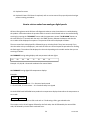
1
Direct Vent Heaters
Troubleshooting Manual
WARNING
There are a number of live tests that are required when fault finding this product. Extreme care should be used
at all times to avoid contact with energized components inside the furnace.
You MUST be a qualified service person before proceeding with these test instructions.
Before checking resistance readings, turn off power source to unit and then isolate each item to be checked
from the circuit by unplugging it.
When setting gas pressures on one of these units, please check the complete model number you are troubleshooting. Gas pressures and dip switches can vary among models. Always check the rating plate for complete
information and follow directions.
CAUTION
Label all wires prior to disconnection when
servicing controls. Wiring errors can cause
improper and dangerous operation.
If any of the original wire as supplied with the appliance must
be replaced, it must be replaced with type 18 AWG wire or its
equivalent.
1
06212013GW
Table of Contents
Code Numbers
Page #
Lo – Hi = Analog Indicator ……………………………………………………………………………………………………………………….4
PF = Digital Read Out.…..…………………………………………………………………………………………………………………………4
60 = Analog Indicator ….………………………………………………………………………………………………………………………….5
11 = Digital Read Out.……………………………………………………………………………………………………………………………..5
LO = Analog Indicator ….…………………………………………………………………………………………………………………………8
12 = Digital Read Out …………………………………………………………………………………………………………………………….8
68 = Analog Indicator..…………………………………………………………………………………………………………………………..10
14 = Digital Read Out ……………………………………………………………………………………………………………………………10
HI = Analog Indicator...………………………………………………………………………………………………………………………….11
16 = Digital Read Out……….……………………………………………………………………………………………………………………11
72, 76 = Analog Indicator………………………………………………………………………………………………………………………12
31 = Digital Read Out …………………………………………………………………………………………………………………………..12
76, 80 = Analog Indicator …………………………………………………………………………………………………………………….13
32 = Digital Read Out ...................………………………………………………………………………………………………………..13
64, 68, 72 = Analog Indicator……………………………………………………………………………………………………………….14
33 = Digital Read Out……………………………………………………………………………………………………………………………14
68, 72, 76 = Analog Indicator ………………………………………………………………………………………………………………15
34 = Digital Read Out……………………………………………………………………………………………………………………………15
LO, 60, 64 = Analog Indicator……………………………………………………………………………………………………………….16
53 = Digital Read Out …………………………………………………………………………………………………………………………..16
60, 64, 68 = Analog Indicator ………………………………………………………………………………………………………………17
61 = Digital Read Out……………………………………………………………………………………………………………………………17
64, 68 = Analog Indicator …………………………………………………………………………………………………………………….18
70 = Digital Read Out …………………………………………………………………………………………………………………………..18
LO, 60 = Analog Indicator………………………………………………………………………………………………………………………19
2
06212013GW
71= Digital Read Out……………………………………………………………………………………………………………………………19
80 = Analog Indicator…………………………………………………………………………………………………………………………..20
72 = Digital Read Out……………………………………………………………………………………………………………………………20
72, 76, 80 = Analog Indicator ………………………………………………………………………………………………………………21
73 = Digital Read Out……………………………………………………………………………………………………………………………21
49 = Digital Read Out …………………………………………………………………………………………………………………………..22
99 = Digital Read Out …………………………………………………………………………………………………………………………..23
How to retrieve codes from analog or digital key panel….………………………………………………………………….24
Rinnai America Corporation • 103 International Drive, Peachtree City, GA 30269
Toll-Free:1-800621-9419 • Phone: 678-829-1700 • www.rinnai.us
© 2013 Rinnai America Corporation. Rinnai is continually updating and improving products; therefore,
specifications are subject to change without prior notice. Local, state, provincial and federal codes must be
adhered to prior to and upon installation.
3
06212013GW
Code LO-HI or PF Troubleshooting Procedure
Power Failure – Electric power has been lost while the appliance was running
WARNING: You must be qualified to perform service on electrical systems to proceed. Turn off the
power supply before replacing any parts or fuses.
1. Ensure power supply is on. Check with meter at receptacle if unsure. If you do not have a meter
plug lamp into receptacle and test.
2. If you have no power at the receptacle, check fuse or circuit breaker feeding this circuit.
3. Verify safety circuit – over heat switches (OHS) or thermo-fuse circuit is not open.
4. Check fuse inside unit. If blown replace with proper size fuse, see markings on fuse for size or
owner’s manual.
5. If fuse is not blown, check to see if your unit has a transformer in it. If it does check for proper
transformer output voltage of each windings or read resistance through each set of windings.
See service manual section under troubleshooting or fault finding for proper voltage readings or
resistance values for each windings. If you fall to get a voltage reading or resistance readings
across either winding, replace the transformer.
6. If the transformer is ok or the unit doesn’t have a transformer, replace the PC board. If PC
board is replaced, refer to service manual for proper dip switch and gas pressure setting
procedures.
4
06212013GW
Code 60 or 11 Troubleshooting Procedure
Missed Ignition – Flame rod current does not reach 1 micro amp within a certain time after the solenoid opens
WARNING: You must be qualified to perform service on electrical and gas systems to proceed. Turn
off the electrical and gas supply before replacing or servicing any parts.
1. Verify circuit feeding appliance is properly grounded. Should have a three prong plug and
receptacle feeding the appliance that is grounded and bonded to the circuit panel and ground
rod to the home.
2. Verify all gas valves on gas system are open feeding the proper gas pressure to said appliance.
3. Verify all air was purged from gas lines after installation.
4. Verify proper inlet gas pressures are being fed to appliance. Check appliances rating plate for
proper pressures. This plate or label is located on the side of each unit. The minimum listed inlet
pressure MUST be maintained with all gas appliances at the location firing on high fire.
5. Verify proper gas type; ensure the gas supply at this location matches that listed on said
appliance.
6. Verify gas type dip switch on PC board is switch to proper gas type position for older models. On
newer models this can be done through the control panel electronically. See gas pressure sitting
procedure for appliance you are working on for details.
7. Verify igniter is working. Turn off gas valve feeding the appliance. Unplug igniter wire; hold the
igniter wire with an insulated pair of pliers about a 1/4" from a piece of metal. Cycle the unit to
ensure you see a spark when unit is cycling. If not, check ignition system for loose connections,
damaged components or disconnected plugs back to PC board. . If no spark is noted check the
ignition board to verify it is getting the proper voltage from the PC board. See service manual for
proper voltage and connector numbers. Note; there will be no voltage present unless the unit is
going through the ignition cycle.
8. Make sure the ceramic sparker electrode is tight in its mounting bracket. You should not be able
to move it with your finger if gasket is intact. If loose remove it and clean with dollar bill.
Reinstall using new gasket and ensure it is tight when the installation is finished. If the electrode
is loose the tip can drop down and touch the burners creating a short or no spark.
9. Verify the proper flame rod wire is plugged into the proper flame rod on said unit. Some units
have multiple flame rods.
10. Verify the flame rod is tight in its mounting bracket. You should not be able to move it with your
finger if gasket is intact. If loose remove it and clean with dollar bill. Inspect flame rod for cracks.
Reinstall using new gasket and ensure it is tight when installation is finished.
5
06212013GW
11. Look into view window on appliance to see if you ever see a flame in the burner box while the
unit is going through the ignition cycle. If you do that indicates an issue in the flame rectification
circuit. This could be a buildup of carbon or a white substance on flame rod, bad connection at
flame rod, loose or damaged flame rod, bad PC board, gas valve or low inlet gas pressure.
Before replacing the PC board or gas valve continue troubleshooting the steps below.
12. Remove igniter and flame rod and inspect them for carbon or a white substance build-up. Clean
both the igniter and flame rod before reinstalling. In addition inspect the burners under the
igniter for debris or condensate build-up. Blow out burners and burner box with 120 psi of air. If
you remove just the igniter and flame rod assemblies, make sure you have a new flame
rod/igniter gasket. This gasket MUST be replaced if this seal is broken.
13. If you note improper inlet gas pressures check to see if the gas system was properly sized. If you
are in doubt on how to size the gas system, gas piping, regulator or tank contact your utility
company or a professional gas technical or master plumber for assistance. Refer them to the
International Plumbing Code Book for proper sizing.
14. Inspect the vent system for loose joints, improper fittings, failure to meet clearances around
vent terminal outside building. See venting instructions for clearance specifications. Failure to
meet vent terminal clearances can lead to recirculation of combustion gases causing incomplete
combustion which will lead to carbon build up on flame rods. In addition; ensure vent length is
within specifications, jumpers are placed in the correct position and dip switches for vent
lengths has been properly set.
15. Verify the proper venting materials were used at this installation site. See Rinnai venting
instructions for details.
16. Verify proper altitude settings have been met; see high altitude gas pressure setting procedure
for dip switch and manifold gas pressure settings.
17. Check to ensure all two stages regulators are installed at least six foot away from appliance.
Ensure when appliance shuts off the pressure from the two stage regulator doesn't exceed the
maximum inlet pressure for the appliance. To verify this connect your manometer up to the
heater’s gas test port. The inlet pressures should never exceed 10 inches water column for
natural gas or 13.5 inches on propane. If it does the regulator may be defective.
18. Other suggestions:
a. Verify all burners are clear of debris, spider webs or any obstructions.
b. Verify voltage output to gas valve from PC board could be incorrect or intermittent due to a
bad component on PC board, replace PC board.
c. Ensure correct wiring harness is plugged into correct solenoids on gas valve. If you replaced
the gas valve you could have mixed/crossed the wiring harnesses up.
d. Check resistance readings to all gas valve solenoids; refer to tech sheets or service manual
for proper values.
6
06212013GW
e. Check for proper voltage to gas valve solenoids when unit is trying to fire; proper voltages
can be found in tech sheets or service manual. Replace PC board. If PC board is replaced,
refer to service manual for proper dip switch and gas pressure setting procedures.
7
06212013GW
Code LO or 12 Troubleshooting Procedure
Flame Failure
WARNING: You must be qualified to perform service on electrical and gas systems to proceed. Turn
off the electrical and gas supply before replacing or servicing any parts.
1. Verify circuit feeding appliance is properly grounded. Should have a three prong plug and
receptacle feeding the appliance that is grounded and bonded to the circuit panel and ground
rod to the home.
2. Verify all gas valves on gas system are open feeding the proper gas pressure to said appliance.
3. Verify all air was purged from gas lines after installation.
4. Verify proper inlet gas pressures are being fed to appliance. Check appliances rating plate for
proper pressures. This plate or label is located on the side of each unit. The minimum listed inlet
pressure MUST be maintained with all gas appliances at the location firing on high fire.
5. Verify proper gas type; ensure the gas supply at this location matches that listed on said
appliance.
6. Verify gas type dip switch on PC board is switch to proper gas type position for older models. On
newer models this can be done through the control panel electronically. See gas pressure sitting
procedure for appliance you are working on for details.
7. Verify the proper flame rod wire is plugged into the proper flame rod on said unit. Some units
have multiple flame rods.
8. Verify the flame rod is tight in its mounting bracket. You should not be able to move it with your
finger if gasket is intact. If loose remove it and clean with dollar bill. Inspect flame rod for cracks.
Reinstall using new gasket and ensure it is tight when installation is finished.
9. Look into view window on appliance to see if you ever see a flame in the burner box while the
unit is going through the ignition cycle. If you do that indicates an issue in the flame rectification
circuit. This could be a buildup of carbon or a white substance on flame rod, bad connection at
flame rod, loose or damaged flame rod, bad PC board, gas valve or low inlet gas
pressures. Before replacing the PC board or gas valve continue troubleshooting the steps
below.
10. Remove flame rod and inspect them for carbon or a white substance build-up. Clean both the
igniter and flame rod before reinstalling. In addition inspect the burners under the igniter for
debris or condensate build-up. Blow out burners and burner box with 120 psi of air. If you
remove just the igniter and flame rod assemblies, make sure you have a new flame rod/igniter
gasket. This gasket MUST be replaced if this seal is broken.
11. If you note improper inlet gas pressures check to see if the gas system was properly sized. If you
are in doubt on how to size the gas system, gas piping, regulator or tank contact your utility
8
06212013GW
company or a professional gas technical or master plumber for assistance. Refer them to the
International Plumbing Code Book for proper sizing.
12. Inspect the vent system for loose joints, improper fittings, failure to meet clearances around
vent terminal outside building. See venting instructions for clearance specifications. Failure to
meet vent terminal clearances can lead to recirculation of combustion gases causing incomplete
combustion which will lead to carbon build up on flame rods. In addition; ensure vent length is
within specifications, jumpers are placed in the correct position and dip switches for vent
lengths has been properly set.
13. Verify the proper venting materials were used at this installation site. See Rinnai venting
instructions for details.
14. Verify proper altitude settings have been met; see high altitude gas pressure setting procedure
for dip switch and manifold gas pressure settings.
15. Check to ensure all two stages regulators are installed at least six foot away from appliance.
Ensure when appliance shuts off the pressure from the two stage regulator doesn't exceed the
maximum inlet pressure for the appliance. To verify this connect your manometer up to the
heater’s gas test port. The inlet pressures should never exceed 10 inches water column for
natural gas or 13.5 inches on propane. If it does the regulator may be defective.
16. Other suggestions:
a. Verify all burners are clear of debris, spider webs or any obstructions.
b. Verify voltage output to gas valve from PC board could be incorrect or intermittent
due to a bad component on PC board, replace PC board.
c. Ensure correct wiring harness is plugged into correct solenoids on gas valve. If you
replaced the gas valve you could have mixed/crossed the wiring harnesses up.
d. Check resistance readings to all gas valve solenoids; refer to tech sheets or service
manual for proper values.
e. Check for proper voltage to gas valve solenoids when unit is trying to fire; proper
voltages can be found in tech sheets or service manual. Replace PC board. If PC
board is replaced, refer to service manual for proper dip switch and gas pressure
setting procedures.
9
06212013GW
Code 68 or 14 Troubleshooting Procedure
Overheat Safety Device – High limit temperature thermistor or thermo fuse has activated
WARNING: You must be qualified to perform service on electrical and gas systems to proceed. Turn
off the electrical and gas supply before replacing or servicing any parts.
1. Verify appliance air filters are not clogged.
2. Verify the unit is connected to the proper gas type; see rating plate for gas type of unit.
3. Check to ensure this unit has ever been converted from one gas type to another? If it was
converted verify conversion was performed per manufacturer’s specifications. See conversion
procedure for the model number unit at your location.
4. Verify proper clearances were maintained around unit and vent terminals.
5. Inspect the safety circuit wiring harness for loose connectors, damage or broken wires.
6. Ohm out safety circuit to determine if the bi- switch is open or if the issue is a blown thermofuse. Replace any damaged or blown thermo fuses. Before replacing those components
complete the inspection of all items listed below to find your root cause for the failure.
7. Verify all dip switches are set per manufacturer’ recommendations, contact Rinnai for details on
proper settings if you need assistance.
8. Verify low and high fire manifold gas pressures, check using a manometer. Procedure for
checking these pressures can be found in the service manual. If you need assistance contact
Rinnai technical services 24/7 for details on now to check these pressures. You must have a
manometer to check operating gas pressures.
9. Inspect burner manifold, burner assembly for debris build-up or blockage. If you find debris
build-up inside the burner assembly clean it out. If heat burner assembly shows signs of
excessive heat replace the heat exchanger.
10. Inspect the front, sides and back of the heat exchanger surface for cracks, separations,
discoloration or damage of any kind. If you find any of the above mentioned items replace the
heat exchanger.
11. Inspect all components inside the unit’s cabinet for signs of excessive heat damage. Take note of
the area around the burner site glass and gasket. If discoloration (black) surface is noted replace
heat exchange.
12. Verify venting is within vent clearance specifications and lengths per manufactures’
recommendation.
13. If code 14 still appears after performing the above inspections, replace PC board. If PC board is
replaced, refer to service manual for proper dip switch and gas pressure setting procedures.
10
06212013GW
Code HI or 16 Troubleshooting Procedure
Over Temperature Cut Off
WARNING: You must be qualified to perform service on electrical and gas systems to proceed. Turn
off the electrical and gas supply before replacing or servicing any parts.
Room temperature is sensed as being above 104°F for longer than 10 minutes.
1. Verify air filter is not clogged.
2. Verify the unit is connected to the proper gas type; see rating plate for gas type of unit.
3. Check to ensure this unit has ever been converted from one gas type to another? If it was
converted verify conversion was performed per manufacturer’s specifications. See conversion
procedure for the model number unit at your location.
4. Verify proper clearances were maintained around unit and its vent termination, see owner’s
manual for proper clearance requirements.
5. Verify vent terminal is not blocked, may have to disassemble to inspect inside termination
air/exhaust chambers.
6. Inspect the room temperature thermistor wiring harness for loose connectors, damage or
broken wires.
7. Ohm out room temperature thermistor to determine if the thermistor is open. See service
manual for proper resistance values.
8.
Replace room temperature thermistor
11
06212013GW
Code 72.76 or 31 Troubleshooting Procedure
Room Temperature Thermistor Disconnected
WARNING: You must be qualified to perform service on electrical systems to proceed. Turn off the
power supply before replacing or servicing any parts.
1. Inspect the room temperature thermistor wiring harness for loose connectors, damage or
broken wires.
2. Verify room temperature thermistor is not sensing cold air from an opening behind the unit
such as an unsealed gas line or vent terminal penetration through an outside wall. Other items
that could cause cold drafts across the thermistor are;
a. Air leaks around doors or windows near the unit
b. Un-insulated walls behind or around the unit. Cold air entering the room drops to the floor
and is drawn to the unit when the appliance is firing. Move the room temperature
thermistor up higher behind unit or just outside the rear covers to see if room temperature
drops to unit’s set point.
3. Ohm out room temperature thermistor to determine if the thermistor is open. See service
manual for proper resistance values.
4. Replace room temperature thermistor
12
06212013GW
Code 76.80 or 32 Troubleshooting Procedure
Room Temperature Thermistor Short Circuit
WARNING: You must be qualified to perform service on electrical systems to proceed. Turn off the
power supply before replacing or servicing any parts.
1. Inspect the room temperature thermistor wiring harness for loose connectors, damage or
broken wires.
2. Ohm out room temperature thermistor to determine if the thermistor is open. See service
manual for proper resistance values.
3. Verify room temperature thermistor is not sensing cold air from an opening behind the unit
such as an unsealed gas line or vent terminal penetration through an outside wall. Other items
that could cause cold drafts across the thermistor are;
a. Air leaks around doors or windows near the unit
b. Un-insulated walls behind or around the unit. Cold air entering the room drops to the floor
and is drawn to the unit when the appliance is firing. Move the room temperature
thermistor up higher behind unit or just outside the rear covers to see if room temperature
drops to unit’s set point.
4. Replace room temperature thermistor
13
06212013GW
Code 64.68.72 or 33 Troubleshooting Procedure
High Limit Thermistor Disconnected
WARNING: You must be qualified to perform service on electrical systems to proceed. Turn off the
power supply before replacing or servicing any parts.
1. Verify air filters are not clogged.
2.
Inspect the high limit thermistor wiring harness for loose connectors, damage or broken wires.
3. Ohm out high limit thermistor to determine if the thermistor is open. See service manual for
proper resistance values.
4. Replace high limit thermistor
14
06212013GW
Code 68.72.76 or 34 Troubleshooting Procedure
High Limit Thermistor Short Circuit
WARNING: You must be qualified to perform service on electrical systems to proceed. Turn off the
power supply before replacing or servicing any parts.
1. Verify air filters are not clogged
2. Inspect the high limit thermistor wiring harness for loose connectors, damage or broken wires.
3. Ohm out high limit thermistor to determine if the thermistor is open. See service manual for
proper resistance values.
4. Replace high limit thermistor
15
06212013GW
Code LO.60.64 or 53 Troubleshooting Procedure
Abnormal Spark Sensed
WARNING: You must be qualified to perform service on electrical systems to proceed. Turn off the
power supply before replacing or servicing any parts.
Sparker doesn’t shut OFF within 20 seconds at time of ignition. 1st spark was not sensed within two
seconds, second spark sense was not continuous for one second after solenoid valve opens
1. Inspect the igniter wire for a loose connection, damage or broken wire.
2. Is spark generator (igniter module) firmly attached to the appliance’s cabinet with a screw? It is
important to have this devise firmly attached for proper ground and proper ignition.
3. Verify igniter is working. Turn off gas valve feeding the appliance. Unplug igniter wire; hold the
igniter wire with an insulated pair of pliers about a 1/4" from a piece of metal. Cycle the unit to
ensure you see a spark when unit is cycling. If not, check ignition system for loose connections,
damaged components or disconnected plugs back to PC board. If no spark is noted check the
ignition board to verify it is getting the proper voltage from the PC board. See service manual or
troubleshooting data sheets for proper voltage and connector numbers.
4. Make sure the ceramic igniter electrode is tight in its mounting bracket. You should not be able
to move it with your finger if gasket is intact. If loose remove it and clean with dollar bill.
Reinstall using new gasket and ensure it is tight when the installation is finished. If the electrode
is loose the tip can drop down and touch the burners creating a short or no spark.
5. Remove igniter and inspect it for carbon or a white substance build-up. Clean the igniter before
reinstalling. In addition inspect the burners under the igniter for condensate build-up, spider
webs or debris. Blow out burners and burner box with 120 psi of air. Anytime you remove the
igniter make sure you have a new igniter gasket. This gasket MUST be replaced if this seal is
broken.
6. Check igniter gap, see service manual for gap setting normally about 3/16”.
7.
Verify proper altitude settings, see high altitude gas pressure setting procedure for dip switch
and manifold gas pressure settings.
8. Verify spark electrode is installed in the correct position.
9. Verify all burner cassettes are in place in burner rack. Sometimes when a unit is dropped the
burners can shift and become dislodged. If you find the burners dislodged loosen the burner
bracket and reseat them.
16
06212013GW
Code 60.64.68 or 61 Troubleshooting Procedure
Abnormal Combustion Fan Motor RPM
WARNING: You must be qualified to perform service on electrical systems to proceed. Turn off the
power supply before replacing or servicing any parts.
1. Check wiring harness for loose, broken or damaged connections from fan motor back to PC
board.
2. Remove fan motor with power supply to product turned off. Inspect blower wheel to ensure it
turns freely.
3. Check fan housing and blower wheel for obstacles that could prevent it from turning.
4. Measure fan motor winding resistance; see service manual or troubleshooting sheets for proper
resistance readings. If windings are open replace motor.
5. If motor windings are within specifications and fan motor turns freely, replace PC board. If PC
board is replaced, refer to service manual for proper dip switch and gas pressure setting
procedures.
17
06212013GW
Code 64.68 or 70 Troubleshooting Procedure
ON/OFF Switch Failure
WARNING: You must be qualified to perform service on electrical systems to proceed. Turn off the
power supply before replacing or servicing any parts.
1. Check wiring harness for loose, broken or damaged connections from ON/OFF Switch back to PC
board.
2. Replace ON/OFF switch
18
06212013GW
Code LO.60 or 71 Troubleshooting Procedure
Main Solenoid, SV1, SV2, SV3, PVO Solenoid Valve Fault
WARNING: You must be qualified to perform service on electrical and gas systems to proceed. Turn
off the gas and power supply before replacing or servicing any parts.
1. Check wiring harnesses to all solenoid valves for loose, broken or damaged connections from
gas valve solenoids back to PC board.
2. Check voltage to all solenoid valves while the unit is trying to fire. If you have proper voltage but
keep getting an error code proceed to the next item.
3. Measure the resistance of all solenoid valves, if any of the solenoid valves are found to be open,
meaning having no resistance replace the gas control valve.
4. If you are still getting a code 71 replace the gas control valve. You may get a good resistance
reading upon unplugging the wires, however under load it could open or you may have a
mechanical problem inside the valve that won't allow the valve open.
5. Replace PC board. If PC board is replaced, refer to service manual for proper dip switch and gas
pressure setting procedures.
19
06212013GW
Code 80 or 72 Troubleshooting Procedure
Flame Rod Failure
WARNING: You must be qualified to perform service on electrical and gas systems to proceed. Turn off
the gas and power supply before replacing or servicing any parts
1. Verify the proper flame rod wire is plugged into the proper flame rod on said unit. Some units
have multiple flame rods.
2. Make sure the ceramic on the flame rod or rods is not cracked or damaged.
3. Inspect condition of flame rod, portion inside burner to ensued it’s not broken or damaged.
4. Replace flame rod or rods.
20
06212013GW
Code 72.76.80.HI or 73 Troubleshooting Procedure
Communication Failure
WARNING: You must be qualified to perform service on electrical systems to proceed. Turn off the
power supply before replacing or servicing any parts.
Data transfer between CPU and E2PROM failed.
1. Unplug power to unit and then reapply to see if code goes away.
2. Replace PC board. If PC board is replaced, refer to service manual for proper dip switch and gas
pressure setting procedures.
21
06212013GW
Code 49 Troubleshooting Procedure
Pressure Sensor Break Down of Disconnected
WARNING: You must be qualified to perform service on electrical systems to proceed. Turn off the
power supply before replacing or servicing any parts.
1. Check wiring harnesses to air pressure switch for loose, broken or damaged connections from
pressure switch back to PC board.
2. Check air pressure switch hoses to blower motor housing in rear of unit for blockage or spider
webs inside hoses.
3. Check to ensure plastic hose connections on rear of unit are not broken or damaged.
4. Check hoses for cracks or deterioration, replace if needed.
5. Replace air pressure switch
6. Replace PC board. If PC board is replaced, refer to service manual for proper dip switch and gas
pressure setting procedures.
22
06212013GW
Code 99 Troubleshooting Procedure
Air Supply or Exhaust Blockage
WARNING: You must be qualified to perform service on electrical and gas systems to proceed. Turn off
the gas and power supply before replacing or servicing any parts.
Inspect the entire vent system inside/outside the home or business. Verify all clearances were met and
the proper vent materials were used.
1.
Perform this test only if the unit is coding out during your service call. Remove the intake and
exhaust pipe behind the unit, fire the product and see if it will operate without the vent system
connected. If the unit operates without coding out at that point that's a great indication the
problem is in the vent system. CAUTION: Never leave a unit operating without the vent system
properly connected. The test mentioned above is only that, a test. If the unit functioned with
the vent disconnected there is a 99.9% chance the issue is in the vent system. Proceed to the
next step below.
2. Verify each section of vent was installed properly.
3. Inspect the vent system to ensure all clearances around vent terminations were met. Improper
clearances will result in recirculation of combustion gases.
4. Make sure the vent length was not exceeded. The proper vent lengths are thirteen total feet
with no more than an eight foot vertical rise and no more than two elbows. See venting
instructions for further details.
5. Inspect vent termination for ice build-up inside or around air chamber outside structure.
7. Remove vent termination and inspect for debris, inspects, water or ice in vent system.
8.
Disconnect all vent joints looking for water, condensation, inspects or other items.
9. Verify vent terminals are installed with the proper clearance from overhangs, grade,
obstructions, walls, porches, etc. Must be at least 12” from window or doors and 12’ above
grade or the highest anticipated snow load. See venting instructions for further clearance
requirements.
10. Remove fan motor and inspect fan wheel, housing, and air duct for any type restriction.
11. Remove burner manifold and inspect for insects or other debris in air channel for restriction.
12. Verify low and high fire manifold pressures are set correctly. See gas pressure setting procedure
for proper settings.
23
06212013GW
13. Replace fan motor
14. Replace PC board. If PC board is replaced, refer to service manual for proper dip switch and gas
pressure setting procedures.
How to retrieve codes from analog or digital panels
All Rinnai EnergySavers with LED have self-diagnostic codes to assist the technician in troubleshooting
the product. Information about the previous faults is stored in the PC board and can be recalled during
servicing by pressing the “ECONOMY” button and the temperature control “UP & DOWN” buttons at
the same time for 2.5 seconds with the unit in the “OFF” position. Release the buttons and then the
error codes will be displayed in sequence. The previous faults will be displayed as follows:
The most recent fault is displayed first followed by up to 10 other faults if they have occurred, If you
miss the codes as they are displayed, , wait until the LED turns off and repeat the procedure for recalling
the faults again. The codes will be displayed on the units depending on the model number that you are
servicing as follows:
ALL FURNACES having analog displays with temperature indicator lights.
LO
60
64
68
72
76
80
HI
Example = 60, 64, 68 = Abnormal combustion fan motor RPM’s.
ALL FURNACES having digital LED temperature displays
Examples
SET
ROOM
1
53
2
14
1 = First code and most recent - 53 = Abnormal spark sensed
2 = Second code, 2nd most recent – 14 = Overheat safety has tripped
On the RHFE263 and RHFE1004 Series product the temperature display shows either the temperature or
error code.
01
71
Example = 01 most recent, then fault code such as 71 indicating a faulty gas solenoid valve.
The number such as 01 will appear followed by the fault code, then 02 followed by the second fault
code, 03 followed by the third fault code and so on.
24
06212013GW