1
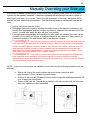
Service Manual
Gulf Stream Electronic
Full Wall Slide Systems
CONTENTS
1217 E. 7th St.
Mishawaka IN
46544
800-334-4712
fax (574) 256-6743
www.powergearus.com
6-05-07
Before you operate the slide system
Operating Instructions
Preventive maintenance
Manually overriding your slide system
Parts List
Wiring Diagram
Teaching the control
Programming without 140-1176
Adjustment information
Troubleshooting guide
Warranty information
Page
2
3
3
4
5-9
10-11
12
13
14
15
16
2
Before you operate the slide system
SYSTEM DESCRIPTION
Your Power Gear Slideout System is a rack and pinion design operated by a 12 Volt DC
electric motor.
MAJOR COMPONENTS
•
•
•
•
Inner rail assemblies are designed to support the room weight.
The 12 Volt DC gearmotor will operate the room using power from the on-board
unit battery.
Slideout systems are equipped with a manual override that allows you to extend /
retract the room in the event of a loss of power.
A specially designed control that gives the user full control of room movement, in
or out. The control has a load sensing capability that stops the motor when the
room is fully extended or retracted.
WARNING
•
ALWAYS MAKE SURE THAT THE SLIDEOUT ROOM PATH IS CLEAR OF PEOPLE
AND OBJECTS BEFORE AND DURING OPERATION OF THE SLIDEOUT ROOM.
•
ALWAYS KEEP AWAY FROM THE SLIDE RAILS WHEN THE ROOM IS BEING
OPERATED. THE GEAR ASSEMBLY MAY PINCH OR CATCH ON LOOSE
CLOTHING CAUSING PERSONAL INJURY.
•
INSTALL TRANSIT BARS (IF SO EQUIPPED) ON THE SLIDEOUT ROOM DURING
STORAGE AND TRANSPORTATION.
3
Operating Modes
EXTENDING THE ROOM
1.
2.
3.
4.
5.
Level the unit.
Verify the battery is fully charged and hooked-up to the electrical system.
Remove the transit bars (if so equipped).
Turn ‘ON’ the on/off switch or key (if so equipped).
Press and hold the IN/OUT switch (Fig. 1) in the OUT position until the room is fully
extended and stops moving.
6. Release the switch, which will lock the room into position. NOTE: If the slideout switch is
held after the room in fully extended, the control will sense that the room has stopped and
will shut off the motor after a few seconds.
7. Turn ‘OFF’ the on/off switch or key (if so equipped).
RETRACTING THE ROOM
1. Verify the battery is fully charged and hooked-up to the electrical system.
2. Turn ‘ON’ the on/off switch or key (if so equipped).
3. Press and hold the IN/OUT switch (Fig. 1) in the IN position until the room is fully
retracted and stops moving.
4. Release the switch, which will lock the room into position. NOTE: If the slideout
switch is held after the room in fully retracted, the control will sense that the room
has stopped and will shut off the motor after a few seconds.
5. Turn ‘OFF’ the on/off switch or key (if so equipped).
6. Install the transit bars (if so equipped).
Preventative Maintenance
Your Power Gear slide-out system has been designed to require very little maintenance. To
ensure the long life of your slide-out system read and follow these few simple procedures.
CAUTION: DO NOT WORK ON YOUR SLIDE-OUT SYSTEM UNLESS THE BATTERY IS
DISCONNECTED.
•
•
When the room is out, visually inspect the inner slide rail assemblies. Check for excess
build-up of dirt or other foreign material; remove any debris or items that may be
present.
If the system squeaks or makes any noises it is permissible to apply a light coating of
silicone spray or lithium grease to the roller and bearing sleeve I.D., removing any
excess lubricant so that dirt or debris do not build-up. DO NOT lubricate the slide-out
drive gears, gear racks, or roller OD as this will attract dirt / debris.
IF YOU HAVE ANY PROBLEMS OR QUESTIONS CONSULT YOUR LOCAL AUTHORIZED
DEALER OR CALL US AT POWER GEAR (800-334-4712)
4
Manually Overriding your Slide-out
In the event of battery / power failure or some other loss of system power, your Full Wall Slide
System can be manually operated. It has been equipped with mechanical override couplers on
each keyed shaft assy. for your use. Due to the size and weight of the room, assistance will be
needed and care taken during the process. Use the following steps to mechanically operate the
room:
1. Unplug each motor near the motor.
2. Disengage each motor brake by pushing the rubber boots in the direction indicated on the
decal to the “disengaged” position (counter clockwise as observed from the boot end of the
motor). A metal lever within the boot will “pop” into position.
3. If enough people are available and wrenches for each shaft are available, the room can be
moved in or out quickly as long as all shafts are turned at the same time. Use a wrench or
socket and ratchet to turn each keyed shaft in the direction required.
!!! WARNING !!!
4.
After the room has been moved in the desired direction, the brake levers on
each motor MUST be returned to the “engaged” position. When the motor brake is disengaged the
slideout room will not lock into place; therefore, the room will not be sealed. When the room has
been manually retracted, be sure to install the transit bars (if so equipped) and return the motor
brake lever to its normal engaged position in order to seal and lock the room into position. Do not
travel unless each motor brake is in the “engaged” position!
5.
!!! WARNING !!!
If the room has been moved while the motor sensing control harness has
been unplugged, do not attempt to use the room again until a service center has re-set the
computerized controller according to the service manuals instructions. Failure to reset the controller
may cause damage to the system or coach.
NOTE: If only one or two people are available to move the room the following procedure must be
followed:
•
•
•
Start at the front of the coach, release the motor brake, rotate that shaft
approximately 1/8 turn, re-apply the motor brake.
Proceed to the rear rail. Release the motor brake, rotate that shaft approximately 1/8
turn, re-apply the motor brake.
Return to the front rail. Repeat this procedure in the above order until the room has
been fully opened or closed as desired.
5
3”X3” Class A Rail Parts List
2)
3)
4)
5)
6)
7)
8)
9)
10)
11)
12)
250-0005
510036
15-1412
18-1032
524035
15-1131
520014
16-1034
15-1130
521336
10-1036
Spur Gear
Sleeve Bearing
Set Screw
Clip Pin
Keyed Shaft
Nut-1/2 13
Outer Roller
Washer Flat
Bolt HD 1/2 13 X5
Woodruff Key
Pin .014X1.25
6
2”X2” class C Rail Parts List
7
3”X 1.5” Class A Rail Parts List- Bolt on Bracket Style
8
3”X 1.5” Class A Rail Parts List- Plate End Style
9
Other Parts
Motor = 1010000803
Encoder = 140-1189
Over ride coupler = 54066
Control = 140-1233
Harness from motor to control 200”= 141-0047200
Harness from motor to control 384”= 141-0050384
Harness from control to wall switch = 141-0004012
(Fuse (each) ¼ amp = 1510000012)
Ramp Left 88.0” = 1010000028
Ramp Left 114” = 1010000092
Ramp Left 141” = 670433
Ramp Left 162” = 1010000274
Ramp Right 91.5” = 670430
Ramp Right 116.5” = 1010000611
Ramp Right 144” = 1010000275
Felt Seal (per inch) = DN12437
10
Class
ADIAGRAM
Coach Wiring Diagram
WIRING
Use these buttons
when resetting the
stop points (If the
programming box
is not being used).
Additional safety switches such as door switches, seat
switches, room lock switches, bed switches, etc.
may be in the system depending on each model. All of these
switches are designed to prevent room operation unless
certain conditions exist i.e. door between slide room and
bathroom is stored in travel position. If ANY of the switches
has failed to close, the room will NOT operate.
11
Class C Coach Wiring Diagram
14 gage red signal feed
fused at .25 amp
12
Teaching the control
When using the 140-1176 control programmer, follow these instructions exactly. Failure
to do so may result in failure to program properly.
1.
2.
3.
4.
Move the “Teach/Run” switch to “Run”.
Press the “Field Reset” IN & OUT buttons simultaneously for about 1 second.
Move the “Teach/Run” switch to “Teach”.
Make sure each motor moves IN when “IN” is pressed. This is easier to check if you do this
one motor at a time.
• Switch M2 off. Momentarily press the “IN” button to see if M1 motor moves the slide in. If
not switch direction with the a-b switch under M1.
• Check the other motor by turning M2 on and M1 off. Momentarily press the “IN” button to
see if M2 motor moves the slide in. If not switch direction with the a-b switch under M2. If it
is OK turn M2 and M1 both on.
5. Run all of the motors IN until they are in a fully retracted position, turning off individual
motors as necessary to achieve a good seal. Press “Set In” to store the IN position.
6. Run all of the motors OUT until they are in a fully extended position, turning off individual
motors as necessary to achieve a good seal. Press “Set Out” to store the OUT position.
The control should no longer operate in teach mode at this point. Test this by pressing “IN”
or “OUT”. If it moves, the control was not programmed. Start over or find out what went
wrong. If it doesn’t move everything is OK, proceed to step 7.
7. Move the “Teach/Run” switch to the “Run” position. Cycle the room IN and OUT to verify
that the control held the set stop points
8. If you need to re-teach the stop points, repeat the above steps starting at “Move the
Teach/Run switch to Teach”
9. Remove the 4-way programming box harness from the control
10. Replace it with a 4-pin wall switch harness (Power Gear P/N 141-0004012) which should be
hooked up to your wall switch in the coach. (Green = “IN” Blue = “OUT” Red = “12V” wire
to the “center” position on the wall switch)
• It is important that you use this red wire as the 12V source to the switch. The control will
not operate properly if 12V is acquired from another source
• If the room moves the wrong direction when using the wall switch, then you have the
green IN wire and the blue OUT wires backward. Reverse these 2 wires to fix this.
13
Programming without using the 140-1176
control programmer
This procedure is intended as an emergency instruction list for service center
personnel to use in the field. On site personnel may not have ready access to the
programming box. The procedure is best handled with three people. One operating
the wall switch inside the coach, one operating the reset buttons on the control, and
a third person checking room seals.
1. Align the rails. If one or more rails are not in the correct position you must
align them by unplugging the motor on the rail(s) that is the first to reach the
stop point, then the person inside the coach can move the rest of the rails until
another person under the slide room to advise when the rails are aligned.
Then plug the motor back in. This may take a couple of tries. The object is to
get all rails aligned in a row before setting the stop points on the controller.
2. Reset the IN stop point. The reset buttons on the controller are noted in the
picture above. Press the reset button for the IN position in and hold while
moving the room IN until reaching the correct stop point. When the room is in
the correct IN position, release the reset button. This will set the correct
position for all motors. Note: IN must be set before OUT
3. Reset the OUT stop point. Push in and hold the OUT stop reset button while
another person operates the room switch to move the room until it is in the
correct out position. Once the room is in the correct OUT position, release the
OUT reset button. This completes the slide control calibration / programming.
4. Failure to completely hold the button in until finished programming will
require starting over!!!!!!!!
14
FLAT FLOOR ROOM HEIGHT ADJUSTMENT---FLUSH FLOOR STYLE SLIDES
Instructions for setting the room height on a flat floor full wall slide-out system utilizing angled rails.
With the room fully extended• Measure from the top of the first moving slide-out rail to the bottom of the slide-out room
floor up close to the coach. This is dimension “A”.
• Measure from the top of the first moving slide-out rail to the bottom of the slide-out room
floor out near the mounting bracket. This is dimension “B”.
• To calculate dimension “B” use the following formula:
“B” (end bracket height setting)=“A” + (slide out room floor thickness) + ¼”.
EXAMPLE:
“B” (end bracket height setting)=“A” + (slide out room floor thickness) + ¼”.
If “A” = 3-1/4”
Then “B”=3-1/4” + 1” + ¼” = 4-1/2”
•
Perform this check on each slide-out rail independent of the other.
NOTE:
1) These figures are approximates. Each coach may be slightly different.
2) Refer to manufacturer of coach/trailer for correct slide out room floor thickness.
15
TROUBLE SHOOTING
Description of Problem
Motor(s) will not run. LED
lights DO NOT light up on
bottom of the control
when button is pushed to
move the room.
Solution
Check all connections.
Make sure driver seat is pulled all the way forward and switch is closed
Make sure parking brake is set and switch is closed
Make sure the engine is running.
Make sure the bed has been retracted (folded up to make it shorter)
Make sure room locks are in open position and safety switches are closed (if so
equipped)
Make sure any other safety switches such as door switches are closed.
Make sure that 12 v signal going out on the red wire comes back on the green
wire when the room switch is depressed to the “IN” position and blue wire when
the switch is depressed into the “OUT” position. If no voltage check in line fuse
at the control box wire labeled “14 GA. red signal feed-fused”
Check fuse for that motor on the controller.
Check for proper voltage to the controller while under load, (11 volts min!!)
Check that harnesses are connected to proper plug.
The control is not trying to move the room indicating that the program may have
been erased. Try reprogramming the control with tool 140-1176 and instructions
included earlier in this manual.
Motors do not move the
room. LED lights DO light
up on bottom of the
control when button is
pushed to move the room.
Measure voltage on the black and red wires going to each motor. Make sure one
is positive and one is ground. If both are the same (positive or negative) the
control is faulty and will need to be replaced.
If you have a spare harness, hook it up outside the vehicle as a test. If you do
not have a spare harness, proceed with the following tests.
While plugged in, test for AC voltage on the Green and Blue wires. When the
room is running they should have 2.5 volts Alternating Current. Also check for
AC voltage between the Green and Yellow wires (should also be 2.5 volts AC
when running and plugged in). Failure here indicates a bad encoder on the
motor or a bad wiring harness from the motor to the control.
While UN-plugged test DC voltage between the orange and green wires (- test
lead on the Green wire and + lead on the Orange wire). Voltage should be 5.6
VDC.
These wires supply power to the motor position sensors. They run between the
motors and the control. Failure here indicates a bad encoder on the motor or a
bad wiring harness from the motor to the control.
Check for mechanical problems such as skipping teeth or pinion to rack gear
alignment.
Motors run in opposite
directions.
Room does not stop
coming in- or does not
stop going out.
Rooms seems “weak”
Reprogram the motor direction using the Programming harness or reverse the
motor leads, AND center two sensor leads. (de-pinning tool will be required as
splices are not acceptable)
Need to reprogram stops with 140-1176 tool.
Check voltage at each motor while the room is climbing the ramp. Repair wiring
or batteries if voltage falls below 10.5 volts.
Check for excessive weight in slide system.
Check for proper room height setting.
Check for proper room alignment within the seals/wall opening.
16
WARRANTY
Power Gear warrants to the original retail purchaser that the product will be free from
defects in material and workmanship for a period of (5) years following the retail sales date
later than 9-1-05. Labor to repair these components will be covered for two years. Power
Gear will, at its option, repair or replace any part covered by this limited warranty which,
following examination by Power Gear or its authorized distributors or dealers, is found to
be defective under normal use and service. No claims under this warranty will be valid
unless Power Gear or its authorized distributor or dealer is notified in writing of such claim
prior to the expiration of the warranty period. Warranty is transferable pending
documentation of original sale date of product.
THIS WARRANTY SHALL NOT APPLY TO:
• Failure due to normal wear and tear, accident, misuse, abuse, or negligence.
• Products which are modified or altered in a manner not authorized by Power Gear in
writing.
• Failure due to misapplication of product.
• Telephone or other communication expenses.
• Living or travel expenses.
• Overtime labor.
• Failures created by improper installation of the product’s slideout system or slideout room
to include final adjustments made at the plant for proper room extension/retraction; sealing
interface between slideout rooms and side walls; synchronization of inner rails; or improper
wiring or ground problems.
• Failures created by improper installation of leveling systems, including final adjustments
made at the plant, or low fluid level, wiring or ground problems.
• Replacement of normal maintenance items.
There is no other express warranty other than the foregoing warranty. THERE ARE NO
IMPLIED WARRANTIES OF MERCHANTIBILITY OR FITNESS FOR A PARTICULAR
PURPOSE. IN NO EVENT SHALL POWER GEAR BE LIABLE FOR ANY INCIDENTAL OR
CONSEQUENTIAL DAMAGES. This warranty gives you specific legal rights, and you may
also have other rights, which vary from state to state. Some states do not allow the
limitations of implied warranties, or the exclusion of incidental or consequential damages,
so the above limitations and exclusions may not apply to you.
For service contact your nearest Power Gear authorized warranty service facility or call 1800-334-4712. Warranty service can be performed only by a Power Gear authorized service
facility. This warranty will not apply to service at any other facility. At the time of requesting
warranty service, evidence of original purchase date must be presented.