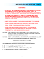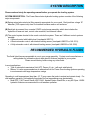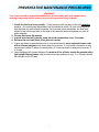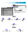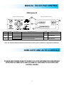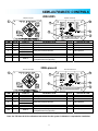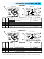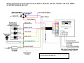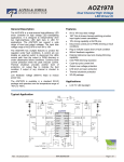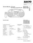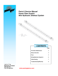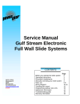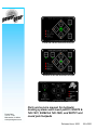
1
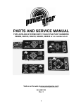
# 500675 & 140-1231 Semi-auto touchpad # 500629 & 140-1226 Automatic touchpad # 500731 Manual touchpad Power Gear 1217 E. 7th St. Mishawaka, IN 46544 www.powergearus.com Parts and service manual for hydraulic leveling systems with touch pad #’s 500675 & 140-1231, 500629 & 140-1226, and 500731 and round jack footpads Released June, 2006 82-L0506 TABLE OF CONTENTS Page 2: Table of Contents Page 3: Warning/Before you operate the system Page 4: System description/Recommended fluids Page 5: Preventive maintenance Page 6: Replacement jacks Page 7: Pump assemblies Page 9: Manifold (valve) assemblies Page 10: Fluid Sensors Page 11: Hoses Page 12: System controls Page 15: Wiring diagram Page 16: Troubleshooting Page 20: Warranty 2 BEFORE YOU SERVICE THE COACH WARNING DO NOT USE THE POWER GEAR HYDRAULIC LEVELING SYSTEM (OR AIR SUSPENSION) TO SUPPORT VEHICLE WHILE UNDER COACH OR CHANGING TIRES. THE HYDRAULIC LEVELING SYSTEM IS DESIGNED AS A ‘LEVELING’ SYSTEM ONLY. TIRE REPAIRS SHOULD BE PERFORMED BY A TRAINED PROFESSIONAL. ATTEMPTS TO CHANGE TIRES WHILE SUPPORTING THE VEHICLE WITH THE HYDRAULIC SYSTEM COULD RESULT IN DAMAGE TO THE MOTOR HOME AND/OR CAUSE SERIOUS INJURY OR EVEN DEATH. KEEP PEOPLE CLEAR OF COACH WHILE LEVELING SYSTEM IS IN USE. NEVER LIFT THE WHEELS OFF THE GROUND TO LEVEL THE COACH. DOING SO MAY CREATE AN UNSTABLE CONDITION. NEVER EXPOSE HANDS OR OTHER PARTS OF THE BODY NEAR HYDRAULIC LEAKS. HIGH PRESSURE OIL LEAKS MAY CUT AND PENETRATE THE SKIN CAUSING SERIOUS INJURY. CAUTION - PARK THE COACH ON A REASONABLY SOLID SURFACE OR THE JACKS MAY SINK INTO GROUND. ON SOFT SURFACES, USE LOAD DISTRIBUTION PADS UNDER EACH JACK. CAUTION - CHECK THAT POTENTIAL JACK CONTACT LOCATIONS ARE CLEAR OF OBSTRUCTIONS OR DEPRESSIONS BEFORE OPERATION. BEFORE YOU OPERATE THE SYSTEM: The leveling system shall only be operated under the following conditions: 1. 2. 3. 4. The coach is parked on a reasonably level surface. The coach "PARKING BRAKE" is engaged. The coach transmission should be in the neutral or park position. The ignition is in the run position, or engine is running. 3 SYSTEM DESCRIPTION Please read and study the operating manual before you operate the leveling system. SYSTEM DESCRIPTION - The Power Gear electro-hydraulic leveling system consists of the following major components: (A) Spring return jacks rated at a lifting capacity appropriate for your coach. Each jack has a large 10" diameter (78.5 square inch) shoe for maximum surface area on soft surfaces. (B) Each jack is powered from a central 12VDC motor/pump assembly, which also includes the hydraulic oil reservoir tank, control valve manifold, and solenoid valves. (C) The control system located in the coach controls the system. There are 3 different control systems possible: A Manual control with bubble level (touchpad # 500731). A Semi-automatic control, with internal leveling sensor (touchpad # 500675 or 140-1231). A fully automatic control, with internal leveling sensor (touchpad # 500629 or 140-1226) RECOMMENDED HYDRAULIC FLUIDS The fluids listed here are acceptable to use in your pump assembly. Contact coach manufacturer or selling dealer for information about what specific fluid was installed in your system. Please consult factory before using any other fluids. In most applications, Type A automatic transmission fluid (ATF, Dexron III, etc.,) will work satisfactorily. Mercon V is also recommended as an alternative fluid for Power Gear leveling systems operating in environments with large temperature swings Operating in cold temperatures (less than -10 F) may cause the jacks to extend and retract slowly. For cold weather operation, fluid specially-formulated for low temperatures may be desirable, Mobil DTE 11M, Texaco Rando HDZ-15HVI, Kendall Hyden Glacial Blu, or any Mil. Spec. H5606 hydraulic fluids are recommended for cold weather operation. 4 PREVENTATIVE MAINTENANCE PROCEDURES WARNING: Your coach should be supported at both front and rear axles with jack stands before working underneath, failure to do so may result in personal injury or death. 1. Check the fluid level every month. Fill the reservoir with the jacks in the fully retracted position. On vertical pump assemblies, the fluid should be within 1/4 inch of the fill port lip and checked only with all jacks retracted. On horizontal pump assemblies, the fluid level should be up to the weep hole on the side of the reservoir tank and checked only with all jacks retracted. 2. Change fluid every 24 months. 3. Inspect and clean all hydraulic pump electrical connections every 12 months. 4. Remove dirt and road debris from jacks as needed. 5. If jacks are down for extended periods, it is recommended to spray exposed chrome rods with a silicone lubricant every seven days for protection. If your coach is located in a salty environment (within 60 miles of coastal areas), it is recommended to spray the rods every 2 to 3 days. 6. Jacks equipped with grease fittings at the bottom of the cylinder should be greased with a light weight lithium grease using a hand pump style grease gun only. 2 or 3 pumps should be sufficient for 20-30 uses. 5 REPLACEMENT JACKS (LEGS) Internal Spring External Spring Measurements in inches Internal Spring Jacks and Rebuild Kits Leveling jack # Rebuild kit # 500385 kit # 800137S 500070 kit # 800131S 500145 kit # 800131S 500386 kit # 800130S 500620 kit # 800130S 500620 has a mounting pad width of 7.25 External Spring jacks Jack # Spring # Rebuild kit # 500082 500094 kit # 800129S 500146 500094 kit # 800129S 500272 500094 kit # 800129S 500235 500252 kit # 800129S 500498 500252 kit # 800129S 500384 500590 kit # 800132S 500598 500590 kit # 800132S 500482 500591 kit # 800132S 500600 500591 kit # 800132S Power Level Jacks Jack # Spring # Rebuild kit # 500730 500591 kit # 800133S 500832 500591 kit # 800133S 500842 500591 kit # 800133S 500876 500591 kit # 800133S 500933 500591 kit # 800133S 500759 500094 kit # 800138S 500833 500094 kit # 800138S 500843 500094 kit # 800138S 500932 500094 kit # 800138S 500800 500094 kit # 800199S Power Level Jack Dimensions A=22.25 A=22.25 A=22.25 A=22.375 A=22.375 B=3.625 B=4.0 B=4.0 B=4.5 B=4.5 Dimensions A=20.75 A=20.75 A=20.75 A=18.3 A=18 A=21.25 A=21.25 A=18 A=18 B=3.25 B=3.25 B=3.25 B=3.25 B=3.25 B=2.625 B=2.625 B=2.625 B=2.625 (800132 kits for 2001 and later only) (800132 kits for 2001 and later only) (800132 kits for 2001 and later only) (800132 kits for 2001 and later only) Dimensions A=19.15 A=23.25 A=20.4 A=18.94 A=19.75 A=20.85 A=23.15 A=21.15 A=25.3 A=19.2 B=2.25 B=2.25 B=2.25 B=2.25 B=2.25 B=2.6 B=2.6 B=2.6 B=2.6 B=3.25 C=16 C=22.3 C=19.5 C=17.0 C=17.75 C=17.6 C=22.2 C=20.2 C=24.4 C=16.75 6 D= 8.0 D= 8.0 D=14.3 D=12.3 D=12.3 D= 8 D=14.3 D=14.3 D=14.3 D= 8.0 E=2.5 E= .5 E=1.5 E=3.0 E=1.0 E=5.0 VERTICAL PUMP ASSEMBLIES 2003 - PRESENT 1 10 2 11 3 9 4 8 6 7 5 ITEM 1 - 11 8,9 2 4 6 5 7 See Fluid Sensors, Page 10 11 10 1 3 1,2,4,5,6 9 PART # 500721 500888 500893 500911 500505 500641 500595 500454 800302 800036S 07-1238 130-1214 130-1214 030-1040 07-1239 500118 500199 500450 500119 500299 500661 500894 500097 500440 500310 500685 13-1100 13-1138 130-1162 130-1189 500099 500439 DESCRIPTION Complete power unit (1.5 gal. capacity) Complete power unit w/ manual override valves Complete power unit Complete power unit Valve manifold assembly (used w/ pump # 500893) Valve manifold assembly (used w/ pump # 500721) Valve manifold assembly (used w/ pump # 500911) Valve manifold assembly w/ manual override valves (used w/ 50088) Motor + Bearing Tank replacement service kit (2.0 gal only) Fill plug Breather cap/dip stick (used with pump # 500911 only) Push-in breather cap and dipstick Grommet, push-in breather cap Drain plug Fluid sensor assembly Fluid sensor assembly with 1k ohm resistor Fluid sensor assembly w/ Packard connector (American Coach) 90 degree fluid sensor assembly 90 degree fluid sensor assembly w/ Packard connector Pump harness Pump harness w/ Packard connectors Dump valve assembly Dump valve assembly w/ manual override Motor solenoid Air breather Pump/motor assy. (used with pump assembly # 500893) Pump/motor assy. (used with pump assembly # 500721) Pump/motor assy. (used with pump assembly # 500888) Pump/motor assy. (used with pump assembly # 500911) Leg valve assembly Leg valve assembly w/ manual override 7 QTY APPLICATION 1 2003 - present 1 1999 - present 1 2003 - present 1 1999 - present 1 1999 - present 1 1 1 1 1 1999 - present 1993 - 1999 2000 - present 1995 - present 1993 - 1998 1995 - 1998 1 1 2003 - present 1 1994 - present 1 1 1 1999 - present 1999 - present 1999 - present 1 2003 - present 3 1994 - present HORIZONTAL PUMP ASSEMBLIES 2003 - PRESENT 4 1 6 3 2 Weep Hole THE DIFFE RE NCE IS IN THE DETAILS HYDRAULIC POWER UNIT 5 level ™ P /N: SIZ E: S /N: MISHAWAKA, INDIANA 500812 9 “A” 8 ITEM PART # 1-8 500773 500781 500825 1-9 500197 500910 500920 500925 501000 501013 1-2 500772 500960 500641 1-2 1 3 4 5 6 7 8 9 500959 500099 500439 140-1146 130-1213 130-1214 030-1040 130-1194 130-1196 500661 800302 130-1150 130-1151 130-1193 130-1195 500310 500097 500440 7 DESCRIPTION Complete 3-valve pump assy 1.0 gal. capacity w/ manual override valves 1.6 gal. capacity w/ manual override valves 1.0 gal. capacity w/o manual override valves (obsolete) Complete 4- valve pump assy 1.5 gal. capacity w/o manual override valves (obsolete) 1.0 gal. capacity w/o manual override valves (replaces pump # 500825) 1.4 gal. capacity w/o manual override valves 1.4 gal capacity w/ manual override valves 1.0 gal capacity w/ manual override valves 1.4 gal capacity w/ manual override valves Manifold assembly w/ manual override valves Manifold assy. pump #’s 500773 & 500781 Manifold assy. pump #’s 500925 & 501000 Manifold assy. pump # 501013 Manifold assembly w/o manual override valves Manifold assy. pump #’s 500910 and 500920 Leg valve assembly Leg valve assembly w/ manual override Fluid sensor (Horizontal pump assemblies only) (see page 10) Breather cap and dipstick Push-in breather cap and dipstick (pump assy. 500781) Grommet, push-in breather cap 1.0 gal. reservoir (obsolete) 1.4 gal. reservoir (obsolete) Pump harness Motor + Bearing only Pump/motor assy. for power unit assy’s 500773 and 500825 Pump/motor assy. for power unit assy 500781 Pump/motor assy. for power unit assy’s 500910 and 501000 Pump/motor assy. for power unit assy’s 500920 and 500925 Motor solenoid Dump valve assembly w/o manual override Dump valve assembly w/ manual override 8 “A” QTY APPLICATION 11.0” 9.0” 11.0” 1 1 1 2003 - present 2003 - present 2002 - 2004 9.8” 13.3” 13.3” 9.8” 13.3” 1 1 1 1 1 1 1992-1995 2003 - present 2003 - present 2003 - present 2004 - present 2004 - present 1 1 1 2003 - present 2003 - present 2004 - present 1 3 3 1 1 1 1 1 1 1 2003 - present 1994 - present 1994 - present 2002 - present 2002 - present 2003 - present 2003 - present 2003 - present 2003 - present 2002 - present 1 2002 - present 1 1 1 1 1 1 2003 - present 2003 - present 2003 - present 1994 - present 1994 - present 1994 - present 3 OR 4 JACK (LEG) VALVE ASSEMBLY 1999 - PRESENT Valve manifold assembly ITEM PART # 1,3,4 1,3,6 500636S 500637* 500099 500439 500523 500505 500641 500454 500772 500960 500959 5 8 1-7 DESCRIPTION Rear hose connector kit Front hose connector kit Leg valve kit Leg valve kit w/ manual override O-ring kit Valve manifold assembly, pump # 500893 Valve manifold assembly, pump # 500721 Valve manifold assembly, pump # 500888 Valve manifold assembly, pump # 500773 & 500781 Valve manifold assembly, pump # 500925 & 501000 Valve manifold assembly, pump # 501013 *”F” port has 2 springs 9 QTY APPLICATION 1 1 1 1 1 1 1999- present 1999- present 1 2003- present 1994- present 1999- present 1999- present FLUID SENSORS 5 3 2 4 3 ITEM 1 2 3 4 5 PART # 500118 500199 500450 500119 500299 140-1146 DESCRIPTION Fluid sensor Fluid sensor with 1k ohm resistor Fluid sensor w/ Packard connector (American Coach) 90 degree fluid sensor assembly 90 degree fluid sensor assy w/ Packard connector Horizontal pump assy. fluid sensor 10 QTY 1 1 1 1 1 1 APPLICATION 1993-1999 2000 - present 1995 - present 2002 - present HOSES AND FITTINGS Hose # Right hose fitting 080-XX XXX - II A B C D E F G x x Hose fitting at each end Letter Left hose fitting Definition #4 37 deg female swivel end, 7/16-20 thread per S.A.E. J514/J.I.C #6 37 deg female swivel end, 9/16-18 thread per S.A.E. J514/J.I.C 90 deg short bend tube, #4 37 deg female swivel 7/16-20 thread per S.A.E. J514/J.I.C 90 deg short bend tube, #6 37 deg female swivel 9/16-18 thread per S.A.E. J514/J.I.C 45 deg short bent tube, #4 37 deg female swivel 7/16-20 thread per S.A.E. J514/J.I.C #4 37 deg male rigid end 7/16-20 thread per S.A.E. J514/J.I.C #6 37 deg male rigid end 9/16-18 thread per S.A.E. J514/J.I.C Example: Hose assembly # 080-AA264-II is 264 inches long, with #4 37 deg female swivel end fittings on both ends. Fittings: 070-1267 070-1261 070-1269 070-1268 070-1262 Reducers: 070-1263 070-1258 11 MANUAL TOUCH PAD CONTROL 2004-present 500731 touchpad (front view) 500731 touchpad (rear view) 1 4 2 3 ITEM NOTE 1 3 N 4 N PART # DESCRIPTION QTY APPLICATION 500731 Manual system touchpad 1 2004-present 5021-XXX Pump harness 1 2004-present 141-0005XXX Pump harness (with fuse) 5010-XXX Safety interconnect harness 1 2004-present 5018-XXX N=Part not shown “-XXX” = length of harness in inches Note: See TIP Sheet # 204 for calibration instructions for this system. Calibration is required after installation. SEMI AUTO AND AUTO CONTROLS PLEASE SEE POWER GEAR TIP SHEET # 218 FOR INFORMATION REGARDING UPDATING OF SEMI AUTO AND AUTOMATIC LEVELING TOUCH PADS AND CONTROL BOXES 12 SEMI-AUTOMATIC TOUCH PAD CONTROL SEMI-AUTOMATIC CONTROLS 2002-2005 500674 control box 500675 touchpad 1 2 4 6 5 3 ITEM NOTE 1 2 3 N N 4 N 5 6 N PART # DESCRIPTION QTY 500675 500663 5021-XXX 5020-XXX 5018-XXX 5019-XXX 500674 Semi-auto touchpad Obsolete - use 500675S Auxiliary harness Coach interconnect harness 1 1 1 2002-2005 2002-present 2002-present APPLICATION Safety interconnect harness 1 2002-present Touch pad harness Obsolete 1 2002-2005 Control box Obsolete – use 500674S 1 2002-2005 Semi-auto control kit (touchpad, control box, 2002-present 500673 touchpad/control box harness) N=Part not shown “-XXX” = length of harness in inches 2006-present 140-1231 touchpad 140-1230 control box 1 2 4 6 5 3 ITEM NOTE 1 2 3 N N 4 N 5 6 N 1,5,6 PART # 140-1231 500663 5021-XXX 5020-XXX 5018-XXX 141-0045XXX 140-1230 DESCRIPTION QTY APPLICATION Semi-auto touchpad Auxiliary harness Coach interconnect harness 1 1 1 2006-present 2002-present 2002-present Safety interconnect harness 1 2002-present Touch pad harness 1 2005-present Control box 1 2006-present Semi-auto control kit (touchpad, control box, 2002-present 500673 touchpad/control box harness) N=Part not shown “-XXX” = length of harness in inches Note: See TIP Sheet # 152 for calibration instructions for this system. Calibration is required after installation. 13 AUTOMATIC TOUCH PAD CONTROL 2002-2005 1 500629 touchpad 500630 touchpad 2 4 6 5 3 ITEM NOTE 1 2 N 3 4 5 6 N N N PART # 500629 500771 500787 5013-XXX 5021-XXX 5020-XXX 5019-XXX 500630 DESCRIPTION QTY APPLICATION Auto touch pad Obsolete - use 500629S 1 2002-2005 Auxiliary harness 1 2002-present Coach interconnect harness 1 2002-present Safety interconnect harness 1 2002-present Touch pad harness Obsolete 1 2002-2005 Control box Obsolete – use 500630S 1 2002-2005 Automatic control kit (touchpad, control box, 1 500643 2002-present touchpad/control box harness) N=Part not shown “-XXX” = length of harness in inches 2006-present 1 140-1226 touchpad 140-1227 control box 2 4 6 5 3 ITEM NOTE 1 2 N 3 4 5 6 N N N 1, 5, 6 PART # 140-1226 500771 500787 5013-XXX 5021-XXX 5020-XXX 141-0045XXX 140-1227 DESCRIPTION QTY APPLICATION Auto touch pad 1 2006-present Auxiliary harness 1 2002-present Coach interconnect harness 1 2002-present Safety interconnect harness 1 2002-present Touch pad harness 1 2006-present Control box 1 2006-present Automatic control kit (touchpad, control box, 1 500643 2002-present touchpad/control box harness) N=Part not shown “-XXX” = length of harness in inches Note: See TIP Sheet # 153 for calibration instructions for this system. Calibration is required after installation. 14 Wiring diagram for systems with control #’s 500731, 500675 & 140-1231, 500674 & 140-1230, 500629 & 140-1226, 500630 & 140-1227 Leveling Control Box P/N’s: 500630 & 140-1227 500674 & 140-1230 Manual Touch Pad P/N: 500731 * * Horizontal pump assemblies 500773, 500781, and 500825 do not use a dump valve assembly. 15 1 TROUBLESHOOTING SYSTEM WILL NOT TURN ON, INDICATOR LIGHT DOES NOT LIGHT PROBABLE CAUSE Coach ignition not in run position Transmission not in park or neutral Parking brake not set Control has been left on for more than four minutes, auto shut off has occurred CORRECTIVE ACTION Turn ignition to run position Place transmission in park or neutral Set brake Push on/off button twice Pin #5 of the 6 pin connector on the control must have +12 VDC with ignition in run position, check coach fuse or breaker Ground wire disconnected or shorted Pin #1 of the 8 pin connector is the main ground. Test for continuity with ground. Check for voltage at pin #6 at the 6 pin connector on the control. If it has 12v+ make sure pin Neutral safety switch wires shorted #2 also has 12v+. If it is ground, try grounding pin #2. If the control then operates, repair or replace wires or neutral safety switch Parking brake wire not grounded, or Check continuity between pin #1 of the 6 pin connector and ground. If there is no continuity, the switch is bad, the parking brake is not set, or the wires to the switch are bad. faulty parking brake switch No power to control Faulty control If all previous causes and actions do not apply replace control JACKS WILL NOT EXTEND, PUMP IS NOT RUNNING PROBABLE CAUSE CORRECTIVE ACTION Check for power at the blue solenoid signal wire while front or rear button is pushed (pin #3 of the 8 pin connector). If no power, check wires, and control.. Check for +12 VDC at the large battery terminal of the solenoid, if no voltage recharge battery or replace power cable. Add new ground cable from pump motor to chassis battery; check chassis ground connection Check for power at the blue solenoid signal wire while jacks down button is pushed. If no power, check wires, and control. If power is present, connect +12 VDC to motor side terminal of solenoid; if motor runs, replace solenoid Check for continuity between the motor and ground. Connect +12 VDC to motor side terminal of solenoid; if motor does not run, replace pump motor (see TIP sheet 216 for details). If all previous causes and actions do not apply replace control Motor solenoid wire defective No power from battery to pump Bad ground to pump motor Motor solenoid faulty Pump motor faulty Faulty control JACKS WILL NOT EXTEND, PUMP IS RUNNING PROBABLE CAUSE Fluid level low; pump cavitating Pump harness faulty Dump valve stuck open or faulty Pump itself is damaged Leg solenoid wires damaged Valve solenoids mis-wired CORRECTIVE ACTION Fill tank to proper level with automatic transmission fluid see tip sheet 140 Check for ground at the black wire for each solenoid valve. If none, repair the wire. While pushing the button for "jacks down" check for 12 v + at the control wire for each solenoid valve, if none check for voltage at these wires where they exit the controller. If voltage is present, repair the wires. If no voltage is present check the controller for trouble codes (see tip sheet 184). If no trouble codes check for proper signals on the 6 pin harness see "system will not turn on, indicator light does not light ". If proper signals are present, replace the controller. It is possible to use a leg valve to diagnose by swapping the dump valve and one leg valve. If the system then builds pressure the dump valve is bad (the leg that now has the dump valve will malfunction). Replace dump valve and return leg valve to original position. NOTE- If there still is no pressure after swapping the valves, the pump may be faulty. See TIP sheet 215 for pump diagnostic details. See TIP sheet 215 for details. Remove tank and disassemble pump for visual inspection. Check for 12 V + at leg coil wires from control while pushing the button "front" or "rear" for that jacks valve. If no 12 V + signal, check for continuity on each wire between coil and controller. Good wire = bad control. Check for ground at the black wire for each solenoid valve coil. Repair if necessary Check wiring diagrams 16 1 ONLY FRONT JACKS WILL NOT EXTEND, PUMP IS RUNNING PROBABLE CAUSE Leg solenoid wires damaged Valve solenoid coil defective Front jack valve faulty CORRECTIVE ACTION Check for 12 V + at leg coil wires from control while pushing the button "front" or "rear" for that jacks valve. If no 12 V + signal, check for continuity on each wire between coil and controller. Good wire = bad control. Check for ground at the black wire for each solenoid valve coil. Repair if necessary Check coil for continuity, if none replace solenoid coil Replace cartridge valve ANY ONE OF THE REAR JACKS WILL NOT EXTEND, PUMP IS RUNNING PROBABLE CAUSE Leg solenoid wires damaged Valve solenoid coil defective Cartridge valve faulty CORRECTIVE ACTION Check for 12 V + at leg coil wires from control while pushing the button "front" or "rear" for that jacks valve. If no 12 V + signal, check for continuity on each wire between coil and controller. Good wire = bad control. Check for ground at the black wire for each solenoid valve coil. Repair if necessary Check coil for continuity, if none replace solenoid coil Replace cartridge valve ALL JACKS WILL NOT RETRACT OR WILL NOT RETRACT FULLY PROBABLE CAUSE Dump solenoid wires damaged System overfilled with fluid System is operating as if the jacks are already retracted Dump solenoid coil defective Dump cartridge valve faulty CORRECTIVE ACTION Check for 12 V + at leg coil wires from control while pushing the button "front" or "rear" for that jacks valve. If no 12 V + signal, check for continuity on each wire between coil and controller. Good wire = bad control. Check for ground at the black wire for each solenoid valve coil. Repair if necessary Drain fluid to recommended level-see tip 140 Check float switch operation. Check the float switch for proper orientation. Check the system for overfilling. Check for continuity on brown wire from float switch to control. Check for ground to float on black wire. Check coil for continuity, if none replace solenoid Replace valve ANY ONE OR TWO JACKS WILL NOT RETRACT AT ALL PROBABLE CAUSE Broken jack spring (s) Jack coil signal wire faulty Jack coil ground wire faulty Jack solenoid valve coil faulty Jack rod guide is rusted or dirty Jack valve faulty Shunt valve clogged Hose damaged CORRECTIVE ACTION Replace jack spring see tip sheet 34 Pin #5 of the 8 pin connector completes circuit for road side rear jack Pin #6 of the 8 pin connector completes circuit for curb side rear jack Pin #7 of the 8 pin connector completes circuit for front jack (s) Check for continuity, if none replace wire Check for ground at the coil terminal black wire repair if necessary Check coil for continuity, if none replace solenoid Clean chrome rod, grease rod guide if equipped with grease fittings. Otherwise lubricate with silicone fluid. It may be necessary to reseal jack or replace. Replace cartridge valve Remove hose fitting on manifold for that jack, to gain access to valve. Clean valve passages with solvent and compressed air. Replace kinked, or damaged hose (damage may not be visible externally) ANY JACK RETRACTS VERY SLOWLY PROBABLE CAUSE Shunt valve clogged Shunt valve spring damaged Hose damaged Jack rod guide is rusted or dirty Internal failure within jack CORRECTIVE ACTION Remove hose fitting on manifold for that jack, to gain access to valve. Clean valve passages with solvent and compressed air. Replace spring Replace kinked, or damaged hose (damage may not be visible externally) Clean chrome rod, grease rod guide if equipped with grease fittings. Otherwise lubricate with silicone fluid. It may be necessary to reseal jack or replace. Rebuild / replace components or jack as necessary. 2 17 ANY JACK RETRACTS WITH NO POWER, WITH POSSIBLE POPPING SOUND PROBABLE CAUSE CORRECTIVE ACTION Air in system Contaminated fluid Leg solenoid valves stuck open Dump solenoid valve contaminated Dump solenoid valve stuck open All solenoid valves stuck open Jack legs create popping sound Check for coils in hose. Remove the coil if present then extend all jacks to full extension, then retract fully, repeat 4 cycles waiting a few minutes between cycles, check fluid level in between cycles Replace fluid, see page a3, tip sheet 140 and 141. Remove solenoid valve, clean or replace Remove solenoid valve, clean or replace Replace solenoid valve Replace all valves Extend jack legs, clean rod, lubricate with light weight grease if equipped with grease fittings or lubricate with silicone spray Due to changes in temperature, expanding and contracting of fluid will magnify the problem of popping jacks, to help minimize this replace fluid with Mercon V fluid PANEL JACKS DOWN LIGHT WILL NOT GO ON WITH JACKS EXTENDED PROBABLE CAUSE Harness wire faulty Fluid sensor mis-adjusted Fluid sensor faulty Open on the brown wire Defective light on touch pad CORRECTIVE ACTION Check for ground at fluid sensor wires. Brown wire to control should read ground when jacks are down. Other wire should read ground at all times. See tip sheet 30, 54 or 81 for fluid sensor orientation Check fluid sensor for continuity* with jacks extended, if no continuity, replace sensor * continuity: pre 2001 models, resistance should be near zero. For 2001 and newer units, resistance should be near 1 KW Check for continuity between brown wire at float sensor and brown wire at control. If none replace wire. Apply +12 VDC at brown wire to 8 pin harness with key on. If no light. Replace touch pad, control, or both. PANEL JACKS DOWN LIGHT WILL NOT GO OFF WITH JACKS RETRACTED PROBABLE CAUSE Low fluid level Fluid sensor misadjusted Fluid sensor faulty Control faulty CORRECTIVE ACTION Fill tank with automatic transmission fluid see tip sheet 140 See tip sheet 30, 54 or 81 for fluid sensor orientation Check fluid sensor for continuity* with jacks extended, if no continuity, replace sensor * : pre 2001 models, resistance should be near zero. For 2001 and newer units, resistance should be near 1 KW If all other probable causes have been checked, replace control and touch pad. JACKS DOWN LIGHT AND ALARM WILL GO ON WHILE DRIVING, JACKS RETRACTED PROBABLE CAUSE Low fluid level Fluid sensor misadjusted Float sensor faulty Short in harness CORRECTIVE ACTION Fill tank with automatic transmission fluid see tip sheet 140 See tip sheet 30, 54 or 81 for fluid sensor orientation Check fluid sensor for continuity* with jacks extended, if no continuity*, replace sensor: pre 2001 models, resistance should be near zero. For 2001 and newer units, resistance should be near 1 KW Check float switch wires for open circuit. SYSTEM LEVELS OK BUT RETRACTS WHEN KEY IS TURNED OFF PROBABLE CAUSE Improper wiring to 6 pin harness. CORRECTIVE ACTION See tip sheets 195, 196, 197, 199, 200, 204, 205 SYSTEM JUMPS DOWN SLIGHTLY AS KEY IS SHUT OFF PROBABLE CAUSE Improper wiring to 6 pin harness. CORRECTIVE ACTION See tip sheets 195, 196, 197, 199, 200, 204, 205 LEVELING SYSTEM DUMPS WHEN KEY IS PUT INTO ACC POSITION PROBABLE CAUSE Improper wiring to 6 pin harness CORRECTIVE ACTION See tip sheets 195, 196, 197, 199, 200, 204, 205 3 18 SYSTEM WILL NOT AUTO RETRACT WHEN THE CHASSIS IS PUT INTO DRIVE PROBABLE CAUSE CORRECTIVE ACTION Improper wiring to 6 pin harness. See tip sheets 195, 196, 197, 199, 200, 204, 205 Check for voltage at pin #6 at the 6 pin connector on the control. If it has 12v+ make sure pin Neutral safety switch wires shorted #2 also has 12v+. If it is ground, try grounding pin #2. If the control then operates, repair or replace wires or neutral safety switch SYSTEM DOES NOT GO TO CORRECT LEVEL POSITION PROBABLE CAUSE Control / level needs to be recalibrated Faulty control Control box is not mounted in proper orientation CORRECTIVE ACTION See tip sheet 147, 152, or 153, If previous causes and actions do not apply replace control Arrow on control box must point forward. Mounting flange for control box must be on top, with wire harnesses coming out the bottom. TOUCH PAD LIGHTS ARE FLASHING PROBABLE CAUSE Jacks are still down partially Possible trouble code being displayed Coach is in emergency retract mode CORRECTIVE ACTION Press retract all jacks button to allow jacks to fully retract See tip sheet 184 for trouble codes and corrections Fluid low, see tip sheet 140 Sensor in pump tank is misadjusted see tip sheets 30, 54,81 SYSTEM TURNS ON BUT TURNS OFF AS SOON AS A BUTTON IS PUSHED PROBABLE CAUSE Low system voltage CORRECTIVE ACTION Voltage must remain above 10 volts while in operation-check battery condition and connections. 19 4 POWER GEAR LIMITED WARRANTY Power Gear warrants to the original retail purchaser that the product will be free from defects in material and workmanship for a period of (2) years following the retail sales date. Power Gear will, at its option, repair or replace any part covered by this limited warranty which, following examination by Power Gear or its authorized distributors or dealers, is found to be defective under normal use and service. No claims under this warranty will be valid unless Power Gear or its authorized distributor or dealer is notified in writing of such claim prior to the expiration of the warranty period. Warranty is transferable pending documentation of original sale date of product. THIS WARRANTY SHALL NOT APPLY TO: • • • • • • • Failure due to normal wear and tear, accident, misuse, abuse, or negligence. Products which are modified or altered in a manner not authorized by Power Gear in writing. Failure due to misapplication of product. Telephone or other communication expenses. Living or travel expenses. Overtime labor. Failures created by improper installation of the product’s slideout system or slideout room to include final adjustments made at the plant for proper room extension/retraction; sealing interface between slideout rooms and side walls; synchronization of inner rails; or improper wiring or ground problems. • Failures created by improper installation of leveling systems, including final adjustments made at the plant, or low fluid level, wiring or ground problems. • Replacement of normal maintenance items. There is no other express warranty other than the foregoing warranty. THERE ARE NO IMPLIED WARRANTIES OF MERCHANTABILITY OR FITNESS FOR A PARTICULAR PURPOSE. IN NO EVENT SHALL POWER GEAR BE LIABLE FOR ANY INCIDENTAL OR CONSEQUENTIAL DAMAGES. This warranty gives you specific legal rights, and you may also have other rights, which vary from state to state. Some states do not allow the limitations of implied warranties, or the exclusion of incidental or consequential damages, so the above limitations and exclusions may not apply to you. For service contact your nearest Power Gear authorized warranty service facility. Warranty service can be performed only by a Power Gear authorized service facility. This warranty will not apply to service at any other facility. At the time of requesting warranty service, evidence of original purchase date must be presented. Power Gear 1217 E. 7th Street Mishawaka, IN 46544 www.powergearus.com 20 5