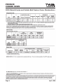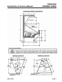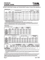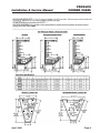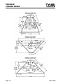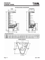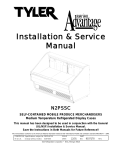
1
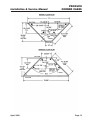
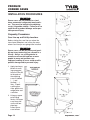
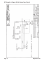
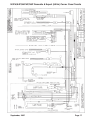
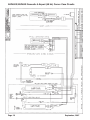
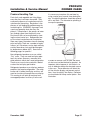
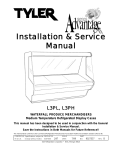
Installation & Service
Manual
PRODUCE CORNER (WEDGE) CASES
PRODUCE SELF-SERVE INSIDE & OUTSIDE CORNER MERCHANDISERS
Medium Temperature & High Performance Refrigerated Corner Display Cases
This manual has been designed to be used in conjunction with the
General (UL/NSF) Installation & Service Manual.
Save the Instructions in Both Manuals for Future Reference!!
This merchandiser conforms to the American National Standard Institute & NSF International Health and Sanitation standard ANSI/NSF 7 - 2003.
PRINTED IN Specifications subject to REPLACES
IN U.S.A.
change without notice. EDITION
12/05
ISSUE
DATE
9/07
Tyler Refrigeration * Niles, Michigan 49120
PART
NO.
9037172
REV.
B
PRODUCE
CORNER CASES
CONTENTS
Page
Specifications
NP Top Display Inside & Outside Corner Merchandisers . . . . . . . . . 4
N3P Waterfall Inside & Outside Corner Merchandisers . . . . . . . . . 6
N4P Multi-Shelf Inside & Outside Corner Merchandisers . . . . . . . . . 8
N5P Multi-Shelf, Extended Height Inside & Outside Corner
Merchandisers . . . . . . . . . . . . . . . . . . . . . . . . . . . . . . . . . . . . . . . . . 11
Pre-Installation Responsibilities . . . . . (See General-UL/NSF I&S Manual)
Installation Procedures
Carpentry Procedures . . . . . . . . . . . . . . . . . . . . . . . . . . . . . . . . . . 14
Case Line-Up and Pull-Up Locations . . . . . . . . . . . . . . . . . . . . . . . 14
Trim & NSF Thermometer Installation . . . . . . . . . . . . . . . . . . . . . . . 15
Electrical Procedures . . . . . . . . . . . . . . . . . . . . . . . . . . . . . . . . . . . 15
Electrical Considerations . . . . . . . . . . . . . . . . . . . . . . . . . . . . . . . . . 15
Case Fan Circuit . . . . . . . . . . . . . . . . . . . . . . . . . . . . . . . . . . . . . . . 15
Fluorescent Lamp Circuit . . . . . . . . . . . . . . . . . . . . . . . . . . . . . . . . . 15
Plumbing Procedures . . . . . . . . (See General-UL/NSF I&S Manual)
Refrigeration Procedures . . . . . (See General-UL/NSF I&S Manual)
Defrost Information . . . . . . . . . . . . . . . . . . . . . . . . . . . . . . . . . . . . 15
Defrost Control Chart . . . . . . . . . . . . . . . . . . . . . . . . . . . . . . . . . . . 15
Wiring Diagrams . . . . . . . . . . . . . . . . . . . . . . . . . . . . . . . . . . . . . . . . . . . 15
NP Dom. & Exp. (50 Hz) Corner Case Circuits . . . . . . . . . . . . . . . . 16
N3P/N4P(HP)/N5P Dom. & Exp. (50 Hz) Corner Case Circuits . . 17
N4P45OS/N5P45IS Dom. & Exp. (50 Hz) Corner Case Circuits . . 18
Cleaning and Sanitation
Component Removal and Installation Instructions for Cleaning 19
Mirrors (N4P/N5P Models) . . . . . . . . . . . . . . . . . . . . . . . . . . . . . . . . 19
Shelves and Shelf Brackets (N4P/N5P Models) . . . . . . . . . . . . . . . 19
Bottom Trays . . . . . . . . . . . . . . . . . . . . . . . . . . . . . . . . . . . . . . . . . . 19
Front Air Ducts . . . . . . . . . . . . . . . . . . . . . . . . . . . . . . . . . . . . . . . . 19
Rear Duct Panels (Models w/o Shelf Light Sockets) . . . . . . . . . . . 19
(Models w/ Shelf Light Sockets) . . . . . . . . . . . . . . . . . . . . . . . . . . . 19
Discharge Air Honeycomb . . . . . . . . . . . . . . . . . . . . . . . . . . . . . . . . 19
Front Lower Cladding . . . . . . . . . . . . . . . . . . . . . . . . . . . . . . . . . . . 20
Front Upper Cladding . . . . . . . . . . . . . . . . . . . . . . . . . . . . . . . . . . . 20
Cleaning Instructions . . . . . . . . (See General-UL/NSF I&S Manual)
Page 2
September, 2007
Installation & Service Manual
PRODUCE
CORNER CASES
Page
General Information
NSF Product Thermometer Installation . . . . . . . . . . . . . . . . . . . . 20
Mirror Installation (N4P/N5P Models) . . . . . . . . . . . . . . . . . . . . . 20
Produce Handling Tips . . . . . . . . . . . . . . . . . . . . . . . . . . . . . . . . . 21
Service Instructions
Preventive Maintenance . . . . . . (See General-UL/NSF I&S Manual)
Connecting the Refrigeration Piping and Components . . . . . . . 24
Compact Lamp Replacement . . . . . . . . . . . . . . . . . . . . . . . . . . . . 24
Discharge Grid Replacement . . . . . . . . . . . . . . . . . . . . . . . . . . . . 24
Fan Blade and Motor Replacement (See Gen.-UL/NSF I&S Manual)
Color Band & Bumper Replacement (See Gen.-UL/NSF I&S Man.)
Parts Information
Operational Parts Lists . . . . . . . . . . . . . . . . . . . . . . . . . . . . . . . . . 25
Cladding and Optional Trim Parts Lists . . . . . . . . . . . . . . . . . . . . 26
TYLER Warranty . . . . . . . . . . . . . . . . . (See General-UL/NSF I&S Manual)
The following Medium Temperature, Top Display, Waterfall and Multi-Shelf, Refrigerated Bulk
Produce Corner Merchandiser models are covered in this manual:
MODELS
DESCRIPTION
NP45IS
45° INSIDE TOP DISPLAY BULK PRODUCE CORNER MERCHANDISER
NP45OS
45° OUTSIDE TOP DISPLAY BULK PRODUCE CORNER MERCHANDISER
NP90OS
90° OUTSIDE TOP DISPLAY BULK PRODUCE CORNER MERCHANDISER
N3PH45IS
45° INSIDE WATERFALL BULK PRODUCE CORNER MERCHANDISER
N3PH45OS
45° OUTSIDE WATERFALL BULK PRODUCE CORNER MERCHANDISER
N4P30IS
30° INSIDE MULTI-SHELF BULK PRODUCE CORNER MERCHANDISER
N4P45IS
45° INSIDE MULTI-SHELF BULK PRODUCE CORNER MERCHANDISER
N4P45OS
45° OUTSIDE MULTI-SHELF BULK PRODUCE CORNER MERCHANDISER
N4PHP45IS
45° INSIDE HIGH PERFORMANCE MULTI-SHELF BULK PRODUCE
MERCHANDSER
N4P90IS
90° INSIDE MULTI-SHELF BULK PRODUCE CORNER MERCHANDISER
N4P90OS
90° OUTSIDE MULTI-SHELF BULK PRODUCE CORNER MERCHANDISER
N5P45IS
45° INSIDE EXTENDED HEIGHT MULTI-SHELF BULK PRODUCE CORNER
MERCHANDISER
N5P90IS
90° INSIDE EXTENDED HEIGHT MULTI-SHELF BULK PRODUCE CORNER
MERCHANDISER
N5P90OS
90° OUTSIDE EXTENDED HEIGHT MULTI-SHELF BULK PRODUCE CORNER
MERCHANDISER
December, 2005
Page 3
PRODUCE
CORNER CASES
SPECIFICATIONS
NP Top Display Inside and Outside Bulk Produce Corner Merchandisers
Page 4
April, 2008
Installation & Service Manual
April, 2008
PRODUCE
CORNER CASES
Page 5
PRODUCE
CORNER CASES
N3PH Waterfall Inside and Outside Bulk Produce Corner Merchandisers
Page 6
April, 2008
Installation & Service Manual
April, 2008
PRODUCE
CORNER CASES
Page 7
PRODUCE
CORNER CASES
N4P(HP) Multi-Shelf Inside and Outside Bulk Produce Corner Merchandisers
Page 8
April, 2008
Installation & Service Manual
April, 2008
PRODUCE
CORNER CASES
Page 9
PRODUCE
CORNER CASES
Page 10
April, 2008
Installation & Service Manual
PRODUCE
CORNER CASES
N5P Ext. Height Multi-Shelf Inside & Outside Bulk Produce Corner
Merchandisers
April, 2008
Page 11
PRODUCE
CORNER CASES
Page 12
April, 2008
Installation & Service Manual
April, 2008
PRODUCE
CORNER CASES
Page 13
PRODUCE
CORNER CASES
INSTALLATION PROCEDURES
WARNING
Corner cases are not intended as stand
alone commercial refrigerated merchandisers. They must be bolted to the adjoining
case(s) to provide stability. Failure to do so
could result in product damage and/or possible personal injury.
Carpentry Procedures
Case Line-up and Pull-Up Locations
Before starting the case line-up, review the
store layout floorplans and survey the areas
where case line-ups are going to be installed.
WARNING
Corner cases can be very heavy and possibly top heavy before they are secured in a
line-up. Always use a lifting device to
remove case from skid and two or more
people to move and position case.
Improper handling of cases could result in
product damage and/or personal injury.
1. Apply two heavy
beads of caulking compound
from the Filler Kit
to the ends of
the adjoining
cases at dotted
(. . .) and
dashed (- - -)
lines. Proper
caulking provides good case
refrigeration and
sanitation.
2. Using an appropriate lifting
device, lift corner
case from skid
and install four
pipe legs.
Lower corner
case to floor.
Page 14
September, 2007
PRODUCE
CORNER CASES
Installation & Service Manual
3. Position corner case at end of case line-up
so front bumpers and case pull-ups line up.
4. Adjust legs inserts in bottom of legs (1), up
to 1 1/2”, to align and level pull-ups and
bumpers. Push corner case tight against
case line-up.
CAUTION
Do not drill or use other holes through the
case end for pull-ups. This may deform the
case ends and could cause joint leaks
and/or poor refrigeration.
5. Secure corner case to case line-up by
installing pull-up bolts and mounting hardware (2) at pull-up locations (A & B) or (A,
B, C & D) as shown on page 10. NOTE:
Do not tighten any pull-up hardware until all
of it has been installed. Tighten all pull-up
hardware equally starting at point A and finishing at point B or D. Do not overtighten.
6. Install kickplate assembly (3) by securing
clips to front legs (1).
7. Install lower front cladding (4) by positioning lower tab behind top of kickplate and
securing top of lower front cladding with
bottom screws from upper front cladding.
Trim & NSF Thermometer Installation
The joint trim and mounting hardware are
shipped loose. Trim includes bumper joint
trim, front upper cladding joint trim, front lower
cladding joint trim and kickplate joint trim.
The NSF product thermometer and bracket
assembly is shipped loose with the case. After
removing the thermometer and bracket assembly from the shipping packaging, position it on
the inside of the front bottom left cutout in the
partition. Secure bracket to partition with two
screws.
Electrical Procedures
Electrical Considerations
CAUTION
Make sure all electrical connections at components and terminal blocks are tight. This
will prevent burning of electrical terminals
and/or premature component failure.
December, 2005
NOTE
The electrical components are located in
the electrical terminal box at the right front
or center front of the case, behind the
lower front cladding.
Case Fan Circuit
This circuit is to be supplied by an uninterrupted, protected 120V circuit. The case fan
circuit is not cycled during defrost on any of
these models.
Fluorescent Lamp Circuit
N3PH, N4P, N4PHP and N5P corner case
lighting is supplied by PL-L folded lamps with
electronic ballasts. It is controlled by a light
switch in each case. The standard lighting is
1-row of horizontal lighting.
Defrost Information
See “General-UL/NSF I&S Manual” for
operational descriptions for Off Time
defrost control.
Defrost Control Chart
Defrost
Type
Off Time*
NP
N3PH
N4P
N4PHP
N5P
Defrost
Defrosts Duration
Per Day
(Min)
3
3
3
2
3
40
40
40
10
40
Term.
Temp.
---------------------
*All produce models are only offered with
Off Time defrost.
WIRING DIAGRAMS
ELECTRICIAN NOTE - OVERCURRENT
PROTECTION
120V circuits should be protected by 15 or 20 Amp
devices per the requirements noted on the cabinet
nameplate or the National Electrical Code, Canadian
Electrical Code - Part 1, Section 28. 208V defrost
circuits employ No. 12 AWG field wire leads for field
connections. On remote cases intended for end to
end line-ups, bonding for ground may rely upon the
pull-up bolts.
The following wiring diagrams on page 16, 17
and 18 will cover all the NP/N3PH/N4P/
N4PHP/N5P produce corner case circuits.
Page 15
NP Domestic & Export (50 Hz) Corner Case Circuits
Page 16
September, 2007
N3PH/N4P/N4PHP/N5P Domestic & Export (50 Hz) Corner Case Circuits
September, 2007
Page 17
N4P45OS/N5P45IS Domestic & Export (50 Hz) Corner Case Circuits
Page 18
September, 2007
Installation & Service Manual
CLEANING AND SANITATION
Component Removal and
Installation Instructions for
Cleaning
PRODUCE
CORNER CASES
Rear Duct Panels
(Models w/o Shelf Light Sockets)
1. Remove mirrors, shelves and/or bottom
trays, see this page.
Mirrors (N3PH/N4P/N4PHP/N5P Models)
2. Remove mounting screws and rear duct
panels from case.
1. Remove mounting screws and end molding
from ends of mirror section(s).
3. After cleaning, replace and secure rear
duct panels in reverse order.
2. Carefully grasp and lift mirror section until
bottom edge clears the lower mirror track.
(Models with Shelf Lights Sockets)
3. Carefully lower mirror section out of upper
mirror track and remove from case.
4. After cleaning, replace in reverse order.
Shelves and Shelf Brackets
(N3PH/N4P/N4PHP/N5P Models)
1. Remove product from shelves.
2. If shelf has a light, unplug the light cord
from the socket in the rear duct panel.
Completely insert socket cover in the light
socket to protect the receptacle.
3. Push shelves back and then lift up and out
to remove them from the shelf brackets.
4. Remove shelf brackets from slots in rear
uprights.
5. After cleaning, replace in reverse order.
Bottom Trays
1. Remove product from bottom of case.
2. Grasp and lift out each lower tray from the
case interior.
3. Remove tray supports from slots in front
and rear ducts.
4. After cleaning, replace in reverse order.
Front Air Ducts
1. Remove bottom trays, see this page.
2. Lift out front air duct sections.
1. Remove mirrors, shelves and bottom
trays, see this page.
2. Remove mounting screws from rear duct
panels.
3. Slowly lift out rear duct panel until the
shelf harness connector near the top of
the panel can be accessed.
4. Desconnect shelf harness connector and
complete removing the rear duct panel.
WARNING
Rear duct panels with electrical receptacles can be cleaned without removing the
electrical receptacles. Do not get moisture
on electrical wires when cleaning under
this cover. Moisture on wires could cause
premature product failure and/or personal
injury or death from electrical shock.
5. After cleaning, reconnect the shelf harness connector and install and secure the
rear duct panels in reverse order.
Discharge Air Honeycomb
(N3PH/N4P/N4PHP/N5P Models Only)
NOTE
Note position of the honeycomb grid during removal so it can be reinstalled the
same way.
1. Remove screws, rear grid retainer and
honeycomb grid from front of top duct
panel.
3. After cleaning, replace in reverse order.
December, 2005
Page 19
PRODUCE
CORNER CASES
CAUTION
Improper installation of the honeycomb
grid could result in improper air flow
and/or poor refrigeration.
GENERAL INFORMATION
NSF Product Thermometer
Installation
2. After cleaning, replace honeycomb grid
as it was removed and secure with rear
grid retainer and screws.
1. Unwrap the thermometer and bracket
assembly shipped loose with the case.
Front Lower Cladding
2. Remove left front return air duct.
1. Remove screws from top of front lower
cladding.
2. Lower top of front lower cladding until
bottom can be remove from top of kickplate support brackets.
3. After cleaning, replace and secure front
lower cladding in reverse order.
Front Upper Cladding
1. Remove front lower cladding. See this
page.
2. Remove screws, bumper joint trim and
upper cladding joint trim from front corners of the case.
3. Remove color band, bumper and bumper
retainer from the case. See “GeneralUL/NSF I&S Manual”.
4. Remove screws from sides of front upper
cladding and remove front upper
cladding.
5. After cleaning, replace front upper
cladding and remaining front components
in the reverse order.
3. Position bracket 1” in from left edge and
just under the bottom return air duct
holes.
4. Mount the bracket to the return air duct
with two self-tapping screws.
5. Replace the front return air duct.
Mirror Installation
(N3PH/N4P/N4PHP/N5P Models)
Most corner cases will have two mirror sections. Make sure the gaps at the ends of
both mirrors are equal. This will prevent any
gap showing when the stainless steel trim is
installed. Also make sure all mirrors have a
good tight seal between each mirror.
NOTE
• Mirror angles have been designed to be
the same as straight cases, but mirror
heights on the back wall of the corner
case may be different due to the case
design.
• Stainless steel trim may need to be cut
and/or notched to fit the gap between
the corner and straight case joint.
Page 20
September, 2007
Installation & Service Manual
Produce Handling Tips
Fresh fruits and vegetable are living things,
even after they have been harvested. They
continue the process of respiration and transpiration after harvesting. Respiration is the
process of self feeding to provide energy for
maintaining life. (EXAMPLE: Asparagus and
sweet corn generate heat after they are
picked.) Transpiration is the process of water
loss through vapor from the plant tissues.
Post-harvest life can be maintained by slowing the rate of water loss. Refrigeration lowers the rate of respiration and transpiration.
Store most types of produce close to freezing
prior to display. There are a number of explanations (ex. Cucumbers can be kept relatively
cool by themselves, but could be damaged
by temperatures below 40°F). See chart on
following pages for specifics.
Non-refrigerated produce cases are called
“Dry” cases. They are used to display potatoes, dry onions, bananas, avocados and
other products which don’t need refrigeration.
These cases can also be used with a bed of
cracked ice to display perishables.
Refrigerated produce cases displays produce
products that require refrigeration. The refrigeration coil is below the display and fans are
used to circulate air through the case display.
This moving air will pick up moisture from
unwrapped produce and carry it to the coil.
December, 2005
PRODUCE
CORNER CASES
It is necessary to replace this moisture by
using a water spray several times during the
day. At night the produce should be covered
wih a wet cloth. The alternate to sprinkling is
to wrap the produce.
In order to maintain case air flow, the return
air duct must not be blocked by product. An
important aid to improve air circulation is to
use air deflectors below the elevated screens
in the case. These deflectors will direct the
air flow into the display and prevent cool air
from “short circuiting” the display. Deflectors
are furnished with hump screen option. See
illustration.
Page 21
PRODUCE
CORNER CASES
Ideal Storage Conditions
Produce
Temperature
Relative
(°F)
Humidity (%)
Display Rack Care
Sell Quickly
(1-2 days)
Refrigerate
(40°F)
Sprinkle
with Water
Special Notes
Avoid bruising
Apples
30-32
85-95
Helpful
No advantage
Apricots
31-32
85-90
Yes
Helpful
No
Asparagus
32-36
90-95
Yes
Profitable
Avocados
40-55
85-90
Yes
No
No
surface
Display on padded
Bananas, Ripe
56-58
85-90
Yes
No
No
Display on padded
surface
For Ripening
58-68
90-95
No
No
Avoid bruising
Beans, Lima
32-40
85-90
Yes
Profitable
No
Shake up to aerate
Beans, Snap
40-45
90-95
Yes
Profitable
Yes
Beets
No
Trim butts and stand
in ice or shallow water
32
85-95
Yes
Profitable
Yes
Moisten roots only
Berries
31-32
90-95
Yes
Helpful
No
Keep well ventilated
Broccoli
32-35
90-95
Yes
Profitable
Yes
Keep out of sun
Brussel Sprouts
Yes
Remove yellow leaves
32-35
90-95
Profitable
Yes
Cabbage
32
90-95
Helpful
Yes
Carrots
32
90-95
Profitable
Yes
bunches
Cauliflower
32
90-95
Yes
Profitable
Yes
Sprinkle only if refrigerated
No
Keep well ventilated
Keep cold to keep sweetness
Celery
31-32
90-95
Yes
Profitable Yes
Cherries
31-32
90-95
Yes
Helpful
Moisten roots only of
Corn, Sweet
31-32
90-95
Yes
Profitable
Yes
Cucumbers
45-50
85-90
Yes
No
No advantage
Eggplants
45-50
85-90
Yes
No
No advantage
Helpful
No advantage
Yes
Helpful
No
Keep well ventilated
Do not bruise, keep on ice
Grapefruit
50-60
85-90
Grapes
30-32
85-95
Honeydews
45-50
85-90
Helpful
No
Cover cut melons with
transparent film
Lemons
38-40
85-90
Helpful
Yes
Sprinkling may be helpful
Profitable
Yes
Avoid soaking with water
Helpful
No advantage
Lettuce
Yes
Remove decayed fruit
32
90-95
Limes
48-50
85-90
Mushrooms
32-35
80-90
Yes
Helpful
No
Handle carefully, keep dry
Muskmelons
32-35
85-90
Yes
Helpful
No
Cover cut melons with
transparent film
Onions, Dry
32
65-70
No
No
Remove loose wrappers,
keep dry
Onions, Green
32
90-95
Profitable
Yes
Keep well ventilated
Yes
Oranges
34-38
85-90
Helpful
No advantage
Parsnips
32
90-95
Helpful
Yes
Moisten roots only
Peaches, Ripe
31-32
90
Yes
Helpful
No
Ripen at room temperature
before storage
Pears
29-31
90-95
Yes
Helpful
No
Display in single or double
layer on pads
32
90-95
Yes
Profitable
Yes
Shake up to aerate, keep cold
Peas, Green
Page 22
Remove decayed fruit
September, 2007
PRODUCE
CORNER CASES
Installation & Service Manual
Ideal Storage Conditions
Produce
Temperature
Relative
(°F)
Humidity (%)
Display Rack Care
Sell Quickly
(1-2 days)
Refrigerate
(40°F)
Sprinkle
with Water
Special Notes
Peppers
45-50
90-95
Yes
Profitable
Yes
Pineapples, Ripe
45-55
85-90
Yes
No
No
Remove decayed fruit
Plums
31-32
90-95
Yes
Helpful
No
Remove decayed fruit
Potatoes
40-50
85-90
No
No
Keep out of sun
Radishes
32
90-95
Yes
Profitable
Yes
Keep water off tops,
avoid tight packing
Rhubarb
32
90-95
Yes
Profitable
No
Trim thin slice off stems
and stand in cold water
Squash, Summer 40-50
85-95
Yes
Helpful
Yes
Winter & Pmpkns 50-55
50-75
No
No
Yes
Profitable
Yes
Spinach
Sweet Potatoes
32
90-95
Keep ventilated
55-60
85-90
No
No
Keep ventilated
32
90-95
Yes
Profitable
No
Trim thin slice off stems
Squash, Summer 40-50
85-95
Yes
Helpful
Yes
Winter & Pmpkns 50-55
50-75
No
No
Profitable
Yes
Keep ventilated
No
No
Keep ventilated
Rhubarb
and stand in cold water
Spinach
Sweet Potatoes
Tangerines
32
90-95
55-60
85-90
Yes
32
85-90
Yes
Profitable
Yes
Remove decayed fruit
Tomatoes, Ripe
45-50
85-90
Yes
Helpful
No
Sell quickly, refrigerate
to hold
Tomatoes, Green
55-70
85-90
No
No
Ripen in back room,
sort frequently
32
90-95
Profitable
Yes
Sprinkle roots only
40-45
80-85
Helpful
No
Cover cut melons with
transparent film
Turnips
Watermelons
The “Produce Handling Chart” is courtesy of Produce Marketing Association, Inc., Newark,
Delaware 19711, from their 1973 Yearbook. This book is published as a service to the Fresh
Produce Industry.
For additional information, consult:
“The Commercial Storage of Fruits, Vegetables, and Florist and Nursery Stocks”, USDA
Handbook No. 66, 1968.
“The Shelf Life of Fresh Fruits and Vegetables - Retail Store Display Cases”, USDA HT&S Office
Report No. 247, October 1951.
“Fresh Fruits and Vegetables - Handling and Care”, Corporate Extension Service, Michigan State
University.
December, 2005
Page 23
PRODUCE
CORNER CASES
SERVICE INSTRUCTIONS
See “General-UL/NSF I&S Manual” for fan
blade & motor and color band & bumper
replacement instructions.
Connecting the Refrigeration
Piping and Components
WARNING
Be sure to position a flame and heatresistent shield over the bottom of the
case liner. Heat from brazing could
damage the liner and/or cause personal
injury or death from fire.
1. Remove lampshield end cap (1).
2. Gently pull down on lamp (2) and lampshield (3) to release end from retainer clip
(4).
3. Unseat and slide off light shield (3) from
lamp (2).
4. Carefully grasp and pull lamp (2) until it
releases from the receptacle (5).
1. Remove screws and refrigeration piping
cover from the left bottom of the case.
5. Insert new lamp (2) in receptacle (5) until
it snaps into place.
2. Position loose refrigeration piping and/or
optional valves between the open lines in
the bottom and upright of the case.
6. Slide on lampshield (3) until it is fully
seated on the receptacle (5).
NOTE
• Make sure all sensor and thermostat
wires are clear of areas being heated.
• Mount all refrigeration lines off the floor
to allow for cleaning access.
3. Apply flux to all joint ends. Starting at one
end, thoroughly heat each new pipe joint
and braze it together. Repeat this process
until all new pipe joints have been brazed.
4. After piping has cooled, route and connect thermostat and sensor wires through
openings in the bottom of the case.
Compact Lamp Replacement
(N3PH/N4P/N4PHP/N5P Models)
CAUTION
Shut off light switch or disconnect power
supply befroe changing a lamp. Lighting
system power and/or ballast surges can
burn out adjacent lamps if power is left on.
Page 24
NOTE
Slot in lampshield must line up with retainer clip to allow for proper lamp securing.
7. Snap lamp (2) and lampshield (3) into
retainer clip (4). Install lampshield end
cap (1) over open end of lampshield (3).
Discharge Grid Replacement
(N3PH/N4P/N4PHP/N5P Models)
1. Remove screws rear grid retainer and
discharge grid.
NOTE
Note position of the honeycomb grid during removal so new grid can be reinstalled
the same way.
CAUTION
Improper installation of the honeycomb
grid could result in improper air flow
and/or poor refrigeration.
2. Position new discharge grid so front
bottom lip is resting on lower lip of front
grid retainer. Install and secure discharge
grid with rear grid retainer and screws.
September, 2007
Installation & Service Manual
PRODUCE
CORNER CASES
PARTS INFORMATION
Operational Parts List
Case Usage
Domestic
Electrical Circuit
115 Volt 60 Hertz
Case Size
All Produce Corners
Fan Motor
5125532
5 Watt
Fan Motor Brackets
(6” Blades)
5213132
(7.75” Blades)
5120098
Fan Bracket Plate
9041077
Fan Blades
(6” 10° 5B) (NP90OS/N3PH45IS)
9403971
(6” 15° 5B) (N4P30IS)
9408191
(6” 21° 5B) (N3PH45OS)
5105621
(6” 27° 5B) (N4PHP45IS)
9023762
(7.75” 32° 5B) (N4P45OS)
5104738
(7.75” 37° 5B) (NP45IS-OS/N4P45IS/
N4P90IS-OS/N5P45IS/N5P90IS-OS)
9454640
Compact Lamp Ballast (N3PH/N4P(HP)/N5P)
(canopy)
5991029
(shelf - 3 rows)
5991030
Compact Lampholder
(N3PH/N4P(HP)/N5P)(can. or shelf)
9450238
Compact Lamp Clip
(N3PH/N4P(HP)/N5P)(can. or shelf)
9450239
Compact Lampsheild
(N3PH/N4P(HP)/N5P)(can. or shelf)
9410790
Anti-Sweat Heater (Light Channel)
(N4P30IS/N3PH45IS-OS/N5P45IS)
9044848
(N4P45OS)
9403434
(N4P90IS/N5P90IS)
9044847
(N4P90OS)
9044846
NSF Product Thermometer
5967100
For information on operational parts not listed above contact the TYLER Service Parts
Department.
December, 2005
Page 25
PRODUCE
CORNER CASES
Cladding and Optional Trim Parts Lists
NP Models
Item Description
45IS
45°OS
90°OS
9456419
9458302
9451538
1
Rear Riser Trim
2
Bumper Joint Trim
------------- color per order -------------
3
Bumper Retainer
------------- color per order -------------
4
Color Band, Ptd.
5
Bumper
6
Upper Front Cladding, Ptd.
9450873
9458241
9450576
7
Lower Front Cladding, Ptd.
9450872
9458242
9450575
8
Kickplate Joint Trim, Ptd.
9452769
N/A
9452784
9
Kickplate, Ptd.
9454863
9458261
9454859
10
Kickplate Support Assembly
9450892
9458238
9450578
11
Pipe Leg, Std. (2” X 9.75”)
9024894 (4)
9024894 (4)
9024894 (4)
12
NSF Product Thermometer
5967100
5967100
5967100
45°IS
45°OS
9400625
9400621
9450870
9452465
9450574
------------- color per order -------------
N3PH Models
Item Description
1
Canopy Joint Trim, Ptd.
2
Bumper Joint Trim
----- color per order -----
3
Bumper Retainer
----- color per order -----
4
Color Band, Ptd.
5
Bumper
6
Upper Front Cladding, Ptd.
9452262
9454666
7
Lower Front Cladding, Ptd.
9452259
9454667
8
Kickplate Joint Trim, Ptd.
9454847
9454736
9
Kickplate, Ptd.
9454855
9454857
10
Kickplate Support Assembly
9452245
9454750
11
Pipe Leg, Std. (2” X 9.75”)
9024894 (4)
9024894 (4)
12
NSF Product Thermometer
5967100
5967100
Page 26
9452253
9454678
----- color per order -----
September, 2007
PRODUCE
CORNER CASES
Installation & Service Manual
N4P/N4PHP Models
Item Description
30°IS
45°IS
45°OS
90°IS
90°OS
9400624
9400625
9400621
9400627
9400623
1
Canopy Joint Trim, Ptd.
2
Bumper Joint Trim
------------------------------ color per order ------------------------------
3
Bumper Retainer
------------------------------ color per order ------------------------------
4
Color Band Ptd.
5
Bumper
6
Upper Front Cladding, Ptd.
9452361
9450973
9452471
9450542
9450576
7
Lower Front Cladding, Ptd.
9452358
9450872
9452468
9450543
9450575
8
Kickplate Joint Trim, Ptd.
N/A
9452769
N/A
9452781
9452784
9
Kickplate, Ptd.
9454869
9454863
9454865
9454861
9454859
10
Kickplate Support Assembly
9451643
9450892
9452393
9450579
9450578
11
Pipe Leg, Std. (2” X 9.75”)
9024894 (4)
9024894 (4)
9024894 (4)
9024894 (4)
9024894 (4)
12
NSF Product Thermometer
5967100
5967100
5967100
5967100
5967100
9451642
9450870
9452465
9450541
9450574
------------------------------ color per order ------------------------------
N5P Model
Item Description
45°IS
90°IS
90°OS
9400625
9400627
9400623
1
Canopy Joint Trim, Ptd.
2
Bumper Joint Trim
------------ color per order ------------
3
Bumper Retainer
------------ color per order ------------
4
Color Band Ptd.
5
Bumper
6
Upper Front Cladding, Ptd.
9450873
9450542
9450576
7
Lower Front Cladding, Ptd.
9450872
9450543
9450575
8
Kickplate Joint Trim, Ptd.
9452769
9452781
9452784
9
Kickplate, Ptd
9454863
9454861
9454859
10
Kickplate Support Assembly
9450892
9450579
9450578
11
Pipe Leg, Std. (2” X 9.75”)
9024894 (4)
9024894 (4)
9024894 (4)
12
NSF Product Thermometer
5967100
5967100
5967100
December, 2005
9450870
9450541
9450574
------------ color per order ------------
Page 27