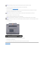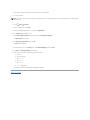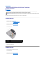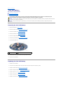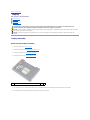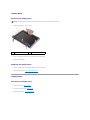
1
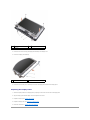
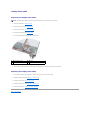
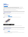
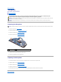
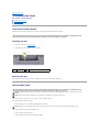
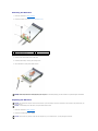
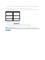
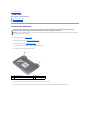
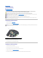
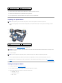
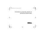
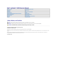
Dell™ Inspiron™ 910 Service Manual Before You Begin
Module Cover
Memory Module
Solid-state Drive
Communication Cards
Keyboard
Palm Rest
Internal Card With Bluetooth® Wireless Technology
Power Button Board
Display
Speaker
Camera (Optional)
System Board
Microphone
Coin-Cell Battery
Flashing the BIOS
Notes, Notices, and Cautions
NOTE: A NOTE indicates important information that helps you make better use of your computer.
NOTICE: A NOTICE indicates either potential damage to hardware or loss of data and tells you how to avoid the problem.
CAUTION: A CAUTION indicates a potential for property damage, personal injury, or death.
Information in this document is subject to change without notice.
© 2008 Dell Inc. All rights reserved.
Reproduction of these materials in any manner whatsoever without the written permission of Dell Inc. is strictly forbidden.
Trademarks used in this text: Dell, the DELL logo, and Inspiron are trademarks of Dell Inc.; Bluetooth is a registered trademark owned by Bluetooth SIG, Inc. and is used by Dell
under license. Microsoft, Windows, a n d Windows XP are either trademarks or registered trademarks of Microsoft Corporation in the United States and/or other countries.
Other trademarks and trade names may be used in this document to refer to either the entities claiming the marks and names or their products. Dell Inc. disclaims any
proprietary interest in trademarks and trade names other than its own.
Model PP39S
August 2008 Rev. A00
Back to Contents Page
Module Cover
Dell™ Inspiron™ 910 Service Manual Removing the Module Cover
Replacing the Module Cover
CAUTION: Before working inside your computer, read the safety information that shipped with your computer. For additional safety best
practices information, see the Regulatory Compliance Homepage at www.dell.com/regulatory_compliance.
CAUTION: Before performing this procedure, turn off the computer, disconnect the AC adapter from the electrical outlet and the computer,
disconnect the modem from the wall connector and the computer, and remove any other external cables from the computer.
NOTICE: To avoid electrostatic discharge, ground yourself by using a wrist grounding strap or by periodically touching an unpainted metal surface (such
as a connector on the back of the computer).
Removing the Module Cover
1.
Follow the instructions in Before You Begin.
2.
Remove the two screws on the module cover.
3.
Lift the cover off the computer at an angle as shown in the figure.
1
module cover
2
module cover tab (3)
3
screw (2)
Replacing the Module Cover
1.
Align the tabs on the module cover to the bottom of the computer and gently replace the module cover.
2.
Replace and tighten the two screws on the module cover.
3.
Slide the battery into the battery bay, until it clicks into place.
4.
Slide the battery-lock latch to the lock position.
Back to Contents Page
Back to Contents Page
Before You Begin
Dell™ Inspiron™ 910 Service Manual Recommended Tools
Turning Off Your Computer
Before Working Inside Your Computer
This section provides procedures for removing and installing the components in your computer. Unless otherwise noted, each procedure assumes that the
following conditions exist:
l
You have performed the steps in Turning Off Your Computer and Before Working Inside Your Computer.
l
You have read the safety information that shipped with your computer.
l
A component can be replaced or—if purchased separately—installed by performing the removal procedure in reverse order.
Recommended Tools
The procedures in this document may require the following tools:
l
Small flat-blade screwdriver
l
Phillips screwdriver
l
Flash BIOS update program CD
NOTE: Flash BIOS update program CD ships only in certain countries when you replace the system board.
Turning Off Your Computer
NOTICE: To avoid losing data, save and close all open files and exit all open programs before you turn off your computer.
1.
Save and close all open files and exit all open programs.
2.
Shut down the operating system:
Windows® XP:
Click Start® Shut Down® Shut down.
Ubuntu® Dell Desktop:
Click
® Quit
® Shut down.
Ubuntu® Classic Desktop:
Click
3.
® Shut down.
Ensure that the computer and all attached devices are turned off. If your computer and attached devices did not automatically turn off when you shut
down your operating system, press and hold the power button until the computer turns off.
Before Working Inside Your Computer
Use the following safety guidelines to help protect your computer from potential damage and to help to ensure your own personal safety.
CAUTION: Before working inside your computer, read the safety information that shipped with your computer. For additional safety best
practices information, see the Regulatory Compliance Homepage at www.dell.com/regulatory_compliance.
NOTICE: Handle components and cards with care. Do not touch the components or contacts on a card. Hold a card by its edges or by its metal
mounting bracket. Hold a component such as a processor by its edges, not by its pins.
NOTICE: Only a certified service technician should perform repairs on your computer. Damage due to servicing that is not authorized by Dell is not
covered by your warranty.
NOTICE: When you disconnect a cable, pull on its connector or on its pull-tab, not on the cable itself. Some cables have connectors with locking tabs; if
you are disconnecting this type of cable, press in on the locking tabs before you disconnect the cable. As you pull connectors apart, keep them evenly
aligned to avoid bending any connector pins. Also, before you connect a cable, ensure that both connectors are correctly oriented and aligned.
NOTICE: To avoid damaging the computer, perform the following steps before you begin working inside the computer.
1.
Ensure that the work surface is flat and clean to prevent the computer cover from being scratched.
2.
Turn off your computer (see Turning Off Your Computer).
3.
If the computer is connected to a docking device (docked), undock it. See the documentation that came with your docking device for instructions.
4.
Press and eject any installed cards from the 3-in-1 memory card reader.
NOTICE: To disconnect a network cable, first unplug the cable from your computer and then unplug the cable from the network device.
5.
Disconnect all telephone or network cables from the computer.
6.
Disconnect your computer and all attached devices from their electrical outlets.
NOTICE: To help prevent damage to the system board, you must remove the battery from the battery bay before you service the computer.
NOTICE: To avoid damage to the computer, use only the battery designed for this particular Dell computer. Do not use batteries designed for other Dell
computers.
7.
Turn the computer over.
1
battery-bay release latch
2
battery
3
battery-lock latch
8.
Slide the battery-bay release latch and the battery-lock latch towards the outer edges.
9.
Slide the battery out of the battery bay.
10.
Turn the computer top-side up, open the display, and press the power button to ground the system board.
Back to Contents Page
Back to Contents Page
Flashing the BIOS
Dell™ Inspiron™ 910 Service Manual Flashing the BIOS From a CD
Flashing the BIOS From the Solid-state Drive in Windows® XP
Flashing the BIOS From the Solid-state Drive in Ubuntu® If a BIOS-update program CD is provided with the new system board, flash the BIOS from the CD. If you do not have a BIOS-update program CD, flash the
BIOS from the solid-state drive.
NOTE: Your computer may or may not ship with an external optical drive. Use an external optical drive or any external storage device for the procedures
that involve discs.
Flashing the BIOS From a CD
1.
Ensure that the AC adapter is plugged in and that the main battery is installed properly.
NOTE: If you use a BIOS-update program CD to flash the BIOS, set up the computer to boot from a CD before inserting the CD.
NOTE: Your computer may or may not ship with an external optical drive. Use an external optical drive or any external storage device for the procedures
that involve discs.
2.
Insert the BIOS-update program CD, and restart the computer.
Follow the instructions that appear on the screen. The computer continues to boot and updates the new BIOS. When the flash update is complete, the
computer will automatically reboot.
3.
Press <0> during POST to enter the system setup program.
4.
Press <Fn> and <F9> to reset the computer defaults.
5.
Press <Esc>, select Save changes and reboot, and press <Enter> to save configuration changes.
6.
Remove the flash BIOS-update program CD from the drive and restart the computer.
Flashing the BIOS From the Solid-state Drive in Windows® XP
1.
Ensure that the AC adapter is plugged in, the main battery is properly installed, and a network cable is attached.
2.
Turn on the computer.
3.
Locate the latest BIOS update file for your computer at support.dell.com.
4.
Click Download Now to download the file.
5.
If the Export Compliance Disclaimer window appears, click Yes, I Accept this Agreement.
The File Download window appears.
6.
Click Save this program to disk and then click OK.
The Save In window appears.
7.
Click the down arrow to view the Save In menu, select Desktop, and then click Save.
8.
Click Close if the Download Complete window appears.
The file icon appears on your desktop and is titled the same as the downloaded BIOS update file.
9.
Double-click the file icon on the desktop and follow the instructions on the screen.
Flashing the BIOS From the Solid-state Drive in Ubuntu® 1.
Ensure that the AC adapter is plugged in and the main battery is properly installed.
2.
Turn on the computer.
NOTE: Your computer may or may not ship with an external optical drive. Use an external optical drive or any external storage device for the procedures
that involve discs.
3.
Click
4.
Create a new folder and name it BIOS.
® Places® Documents.
5.
Locate the latest BIOS update file for your computer at support.dell.com.
6.
Click Download Now to download the file.
7.
If the Export Compliance Disclaimer window appears, click Yes, I Accept this Agreement.
The File Download window appears.
8.
Click Save this program to disk and then click OK.
The Save In window appears.
9.
Click the down arrow to view the Save In menu, select Documents® BIOS, and then click Save.
10.
Click Close if the Download Complete window appears.
11.
Open the terminal command line application and proceed as follows:
a.
Type sudo -s
b.
Type your password
c.
Type cd Documents
d.
Type cd BIOS
e.
Type ./910A00
flash start... string appears.
The computer will restart automatically once the BIOS flash is complete.
Back to Contents Page
Back to Contents Page
Internal Card With Bluetooth® Wireless Technology
Dell™ Inspiron™ 910 Service Manual Removing the Card
Replacing the Card
CAUTION: Before working inside your computer, read the safety information that shipped with your computer. For additional safety best
practices information, see the Regulatory Compliance Homepage at www.dell.com/regulatory_compliance.
NOTICE: To avoid electrostatic discharge, ground yourself by using a wrist grounding strap or by periodically touching an unpainted metal surface (such
as a connector on the back of the computer).
If you ordered a card with Bluetooth wireless technology with your computer, it is already installed.
Removing the Card
1.
Follow the instructions in Before You Begin.
2.
Remove the module cover (see Removing the Module Cover).
3.
Remove the keyboard (see Removing the Keyboard).
4.
Remove the palm rest (see Removing the Palm Rest).
5.
Turn the palm rest over.
1
screw (2)
2
internal card with Bluetooth wireless technology
3
cable
6.
Remove the two screws that secure the card to the palm rest.
7.
Lift the card out of the palm rest.
Replacing the Card
1.
Insert card into the slot and tighten the two screws.
2.
Turn the palm rest over.
3.
Replace the palm rest (see Replacing the Palm Rest).
4.
Replace the keyboard (see Replacing the Keyboard).
5.
Replace the module cover (see Replacing the Module Cover).
6.
Slide the battery into the battery bay, until it clicks in place and slide the battery-lock latch towards the lock position.
Back to Contents Page
Back to Contents Page
Camera (Optional)
Dell™ Inspiron™ 910 Service Manual Removing the Camera
Replacing the Camera
CAUTION: Before working inside your computer, read the safety information that shipped with your computer. For additional safety best
practices information, see the Regulatory Compliance Homepage at www.dell.com/regulatory_compliance.
NOTICE: To avoid electrostatic discharge, ground yourself by using a wrist grounding strap or by periodically touching an unpainted metal surface (such
as a connector on the back of the computer).
Removing the Camera
1.
Follow the instructions in Before You Begin.
2.
Remove the module cover (see Removing the Module Cover).
3.
Remove the keyboard (see Removing the Keyboard).
4.
Remove the palm rest (see Removing the Palm Rest).
5.
Remove the display assembly (see Display Assembly).
6.
Remove the display bezel (see Display Bezel).
1
camera
2
camera cable connector
7.
Disconnect the camera cable from the connector.
8.
Remove the camera board.
Replacing the Camera
1.
Align the camera board over the slot holes and gently replace it.
2.
Reconnect the camera cable to the connector.
3.
Replace the display bezel (see Replacing the Display Bezel).
4.
Replace the display assembly (see Replacing the Display Assembly).
5.
Replace the palm rest (see Replacing the Palm Rest).
6.
Replace the keyboard (see Replacing the Keyboard).
7.
Replace the module cover (see Replacing the Module Cover).
8.
Slide the battery into the battery bay, until it clicks in place and slide the battery-lock latch towards the lock position.
Back to Contents Page
Back to Contents Page
Coin-Cell Battery
Dell™ Inspiron™ 910 Service Manual Removing the Coin-Cell Battery
Replacing the Coin-Cell Battery
CAUTION: Before working inside your computer, read the safety information that shipped with your computer. For additional safety best
practices information, see the Regulatory Compliance Homepage at www.dell.com/regulatory_compliance.
NOTICE: To avoid electrostatic discharge, ground yourself by using a wrist grounding strap or by periodically touching an unpainted metal surface (such
as a connector on the back of the computer).
NOTICE: To help prevent damage to the system board, you must remove the battery from the battery bay before you begin working inside the
computer.
Removing the Coin-Cell Battery
1.
Follow the instructions in Before You Begin.
2.
Remove the module cover (see Removing the Module Cover).
3.
Remove the keyboard (see Removing the Keyboard).
4.
Remove the palm rest (see Removing the Palm Rest).
5.
Remove the display assembly (see Display Assembly).
6.
Remove the system board (see Removing the System Board).
7.
Turn the system board over.
1
coin-cell battery
2
coin-cell battery cable connector
8.
Disconnect the coin-cell battery cable from the system board connector.
9.
Remove the coin-cell battery.
Replacing the Coin-Cell Battery
1.
Replace the coin-cell battery.
2.
Connect the coin-cell battery cable to the system board connector and hold the coin-cell battery in place.
3.
Replace the system board (see Replacing the System Board).
4.
Replace the display assembly (see Replacing the Display Assembly).
5.
Replace the palm rest (see Replacing the Palm Rest).
6.
Replace the keyboard (see Replacing the Keyboard).
7.
Replace the module cover (see Replacing the Module Cover).
8.
Slide the main battery into the battery bay, until it clicks in place and slide the battery-lock latch towards the lock position.
Back to Contents Page
Back to Contents Page
Display
Dell™ Inspiron™ 910 Service Manual Display Assembly
Display Bezel
Display Panel
Display Panel Cable
CAUTION: Before working inside your computer, read the safety information that shipped with your computer. For additional safety best
practices information, see the Regulatory Compliance Homepage at www.dell.com/regulatory_compliance.
NOTICE: To avoid electrostatic discharge, ground yourself by using a wrist grounding strap or by periodically touching an unpainted metal surface (such
as a connector on the back of the computer).
NOTICE: To help prevent damage to the system board, you must remove the battery from the battery bay before you begin working inside the
computer.
Display Assembly
Removing the Display Assembly
1.
Follow the instructions in Before You Begin.
2.
Remove the module cover (see Removing the Module Cover).
3.
Remove the keyboard (see Removing the Keyboard).
4.
Remove the palm rest (see Removing the Palm Rest).
1
Mini-Card antenna cables
5.
Turn the computer over, make note of the cable routing, and carefully dislodge the Mini-Card antenna cables from their routing guides.
6.
Pull the Mini-Card antenna cables through the system board as shown in the figure.
1
display cables
2
Mini-Card antenna cables
3
speaker cable
7.
Disconnect the display cables and the speaker cable from the respective system board connectors.
8.
Make note of the display cables and the speaker cable routing and carefully dislodge from their routing guides as shown in the figure.
9.
Remove the two screws from the display assembly hinges.
10.
Remove the display assembly from the computer base.
1
display cable connectors
2
screw (2)
3
speaker cable connector
Replacing the Display Assembly
1.
Align the display hinges with the holes in the base of the computer and then lower the display into place.
2.
Replace and tighten the two display assembly hinge screws.
3.
Carefully route the display cables and the speaker cable into their routing guides and connect them to the respective system board connectors.
4.
Carefully slide the Mini-Card antenna cables through the system board and into their routing guides.
5.
Replace the palm rest (see Replacing the Palm Rest).
6.
Replace the keyboard (see Replacing the Keyboard).
7.
Replace the module cover (see Replacing the Module Cover).
8.
Slide the battery into the battery bay, until it clicks in place and slide the battery-lock latch towards the lock position.
Display Bezel
Removing the Display Bezel
NOTICE: The display bezel is extremely fragile. Be careful when removing it to prevent damaging the bezel.
1.
1
Follow the instructions in Display Assembly.
display panel
2
display bezel
2.
Using your fingertips, carefully pry up the inside edge of the display bezel.
3.
Remove the display bezel.
Replacing the Display Bezel
1.
Realign the display bezel over the display panel, and gently snap into place.
2.
Follow the instructions in Replacing the Display Assembly.
Display Panel
Removing the Display Panel
1.
Follow the instructions Display Assembly.
2.
Remove the display bezel (see Display Bezel).
3.
Remove the camera (see Removing the Camera).
1
display cover
2
display panel
3
screw (6)
4.
Remove the six screws securing the display panel assembly to the display cover.
5.
Remove the display panel assembly.
1 screw (4 total; 2 on each side)
6.
2 display panel bracket (1 left, 1 right)
Remove the four screws (two on each side) that secure the display panel brackets to the display panel.
Replacing the Display Panel
1.
Attach the display bracket to the display panel by replacing the two screws on each side of the display panel.
2.
Align the display panel with the display cover and replace the six screws.
3.
Replace the camera (see Replacing the Camera).
4.
Replace the display bezel (see Replacing the Display Bezel).
5.
Follow the instructions in Replacing the Display Assembly.
Display Panel Cable
Removing the Display Panel Cable
NOTE: The Display Panel cables and connectors may differ depending on the Display Panel you ordered.
1.
Follow the instructions in Display Assembly.
2.
Remove the display bezel (see Display Bezel).
3.
Remove the camera (see Removing the Camera).
4.
Remove the display panel (see Display Panel).
5.
Turn over the display panel and place it on a clean surface.
1
back of display panel
2
flex cable
3
conductive tape
4
display board connector
6.
Lift the conductive tape that secures the flex cable to the display board connector and disconnect the flex cable.
Replacing the Display Panel Cable
1.
Connect the flex cable to the display board connector and secure it with the conductive tape.
2.
Replace the display panel (see Replacing the Display Panel).
3.
Replace the camera (see Replacing the Camera).
4.
Replace the display bezel (see Replacing the Display Bezel).
5.
Follow the instructions in Replacing the Display Assembly.
Back to Contents Page
Back to Contents Page
Keyboard
Dell™ Inspiron™ 910 Service Manual Removing the Keyboard
Replacing the Keyboard
For more information about the keyboard, see the Dell Technology Guide.
CAUTION: Before working inside your computer, read the safety information that shipped with your computer. For additional safety best
practices information, see the Regulatory Compliance Homepage at www.dell.com/regulatory_compliance.
NOTICE: To avoid electrostatic discharge, ground yourself by using a wrist grounding strap or by periodically touching an unpainted metal surface (such
as a connector on the back of the computer).
NOTICE: To help prevent damage to the system board, you must remove the battery from the battery bay before you begin working inside the
computer.
Removing the Keyboard
1.
Follow the instructions in Before You Begin.
2.
Turn the computer over.
NOTICE: The keycaps on the keyboard are fragile, easily dislodged, and time-consuming to replace. Be careful when removing and handling the
keyboard.
NOTICE: Be extremely careful when removing and handling the keyboard. Failure to do so could result in scratching the display panel.
3.
Remove the two screws from the base of the computer.
4.
Turn the computer top-side up and open the display.
5.
Carefully lift the keyboard and hold it to access the keyboard connector.
6.
Push out the securing tabs that secure the keyboard cable to the system board and remove the keyboard.
NOTICE: The securing tabs that secure the keyboard cable to the system board are fragile. To avoid damage to the securing tabs, do not push them
too far.
1
keyboard
2
keyboard tab (3)
3
keyboard cable
4
securing tab (2)
Replacing the Keyboard
1.
Slide the keyboard cable connector into the slot and push in the securing tabs to secure the keyboard cable to the system board.
NOTICE: The keycaps on the keyboard are fragile, easily dislodged, and time-consuming to replace. Be careful when removing and handling the
keyboard.
2.
Align the tabs on the keyboard to the bottom of the palm rest and keep it in place.
3.
Close the display, turn the computer over.
4.
Replace the two screws in the base of the computer.
5.
Slide the battery into the battery bay, until it clicks into place and slide the battery-lock latch to the lock position.
Back to Contents Page
Back to Contents Page
Memory Module
Dell™ Inspiron™ 910 Service Manual Removing the Memory Module
Replacing the Memory Module
CAUTION: Before working inside your computer, read the safety information that shipped with your computer. For additional safety best
practices information, see the Regulatory Compliance Homepage at www.dell.com/regulatory_compliance.
You can increase your computer memory by replacing the current memory module on the system board with a higher one. See "Basic Specifications" in your
Setup Guide for information on the memory supported by your computer. Install only memory modules that are intended for your computer.
NOTE: Memory modules purchased from Dell are covered under your computer warranty.
Your computer has a user-accessible SODIMM socket that can be accessed from the bottom of the computer.
Removing the Memory Module
NOTICE: To avoid electrostatic discharge, ground yourself by using a wrist grounding strap or by periodically touching an unpainted metal surface (such
as a connector on the back of the computer).
The memory module is located at the bottom of the computer.
1.
Follow the instructions in Before You Begin.
2.
Remove the module cover (see Removing the Module Cover).
NOTICE: To prevent damage to the memory module connector, do not use tools to spread the memory module securing clips.
1
memory module connector
2
securing clip (2)
3
memory module
3.
Use your fingertips to carefully spread apart the securing clips on each end of the memory module connector until the module pops up.
4.
Remove the memory module from the connector.
Replacing the Memory Module
NOTICE: To avoid electrostatic discharge, ground yourself by using a wrist grounding strap or by periodically touching an unpainted metal surface (such
as a connector on the back of the computer).
1.
Follow the instructions in Before You Begin.
2.
Align the notch in the memory module edge connector with the tab in the memory module connector slot.
3.
Slide the memory module firmly into the slot at a 45-degree angle, and rotate the memory module down until it clicks into place. If the module does not
click into place, remove the memory module and reinstall it.
NOTE: If the memory module is not installed properly, the computer may not boot. No error message indicates this failure.
1
tab
2
notch
NOTICE: If the cover is difficult to close, remove the module and reinstall it. Forcing the cover to close may damage your computer.
4.
Replace the module cover (see Replacing the Module Cover).
5.
Slide the battery into the battery bay until it clicks into place and slide the battery-lock latch to the lock position.
6.
Turn on the computer.
As the computer boots, it detects the additional memory and automatically updates the system configuration information.
To confirm the amount of memory installed in the computer:
Windows® XP:
Right-click the My Computer icon on your desktop, then click Properties® General.
Ubuntu®:
Click
Back to Contents Page
® System® Administration® System Monitor.
Back to Contents Page
Microphone
Dell™ Inspiron™ 910 Service Manual Removing the Microphone
Replacing the Microphone
CAUTION: Before working inside your computer, read the safety information that shipped with your computer. For additional safety best
practices information, see the Regulatory Compliance Homepage at www.dell.com/regulatory_compliance.
NOTICE: To avoid electrostatic discharge, ground yourself by using a wrist grounding strap or by periodically touching an unpainted metal surface (such
as a connector on the back of the computer).
NOTICE: To help prevent damage to the system board, you must remove the battery from the battery bay before you begin working inside the
computer.
Removing the Microphone
NOTE: The analog microphone is not present if you have ordered the optional camera. Instead, you will have digital array microphones with the camera.
1.
Follow the instructions in Before You Begin.
2.
Remove the module cover (see Removing the Module Cover).
3.
Remove the keyboard (see Removing the Keyboard).
4.
Remove the palm rest (see Removing the Palm Rest).
1
microphone
2
microphone cable connector
5.
Disconnect the microphone cable from the system board.
6.
Remove the microphone from the computer base.
Replacing the Microphone
1.
Insert the microphone in the slot and connect the microphone cable to the connector on the system board.
2.
Replace the palm rest (see Replacing the Palm Rest).
3.
Replace the keyboard (see Replacing the Keyboard).
4.
Replace the module cover (see Replacing the Module Cover).
5.
Slide the battery into the battery bay, until it clicks in place and slide the battery-lock latch towards the lock position.
Back to Contents Page
Back to Contents Page
Communication Cards
Dell™ Inspiron™ 910 Service Manual Subscriber Identity Module
Wireless Mini-Cards
Subscriber Identity Module
Subscriber Identity Modules (SIM) identify users uniquely through an International Mobile Subscriber Identity.
CAUTION: Before working inside your computer, read the safety information that shipped with your computer. For additional safety best
practices information, see the Regulatory Compliance Homepage at www.dell.com/regulatory_compliance.
Installing the SIM
1.
Follow the instructions in Before You Begin.
2.
In the battery bay, slide the SIM into the compartment.
1
SIM
2
battery bay
Removing the SIM
Press the SIM into the slot to release it. When it is partially ejected, remove the SIM from the battery bay.
Wireless Mini-Cards
CAUTION: Before working inside your computer, read the safety information that shipped with your computer. For additional safety best
practices information, see the Regulatory Compliance Homepage at www.dell.com/regulatory_compliance.
NOTICE: To help prevent damage to the system board, you must remove the battery from the battery bay before you begin working inside the
computer.
NOTE: Dell does not guarantee compatibility or provide support for Mini-Cards from sources other than Dell.
If you ordered a wireless Mini-Card with your computer, the card is already installed.
Your computer supports two Mini-Card slots:
l
Two Full Mini-Card slots - for WLAN and Mobile Broadband or WWAN
NOTE: Depending on the configuration of the computer when it was sold, the Mini-Card slots may not have Mini-Cards installed in them.
Your computer supports two types of wireless Mini-Cards:
l
Wireless Local Area Network (WLAN)
l
Mobile Broadband or Wireless Wide Area Network (WWAN)
Removing the Mini-Card
1.
Follow the instructions in Before You Begin.
2.
Remove the module cover (see Removing the Module Cover).
1
Mini-Card
2
securing screw (2)
3
antenna cable connector (2)
3.
Disconnect the antenna cables from the Mini-Card.
4.
Release the Mini-Card by removing the securing screws.
5.
Lift the Mini-Card out of its system board connector.
NOTICE: When the Mini-Card is not in the computer, store it in protective antistatic packaging. See the information on protection against electrostatic
discharge in the safety information that shipped with your computer.
Replacing the Mini-Card
NOTICE: The connectors are keyed to ensure correct insertion. If you feel resistance, check the connectors on the card and on the system board, and
realign the card.
NOTICE: To avoid damage to the Mini-Card, never place cables under the card.
1.
Follow the instructions in Before You Begin.
2.
Remove the new Mini-Card from its packing.
NOTICE: Use firm and even pressure to slide the card into place. If you use excessive force, you may damage the connector.
3.
4.
5.
Insert the Mini-Card at a 45-degree angle into the appropriate system board connector. For example, the WLAN card connector is labeled WLAN and so
on.
Press the other end of the WLAN card down into the slot on the system board and replace the two securing screws.
Connect the appropriate antenna cables to the Mini-Card you are installing. The following table provides the antenna cable color scheme for each MiniCard supported by your computer.
Connectors on the Mini-Card
Antenna Cable Color Scheme
WWAN (2 antenna cables)
Main WWAN (white triangle)
white with gray stripe
Auxiliary WWAN (black triangle)
black with gray stripe
WLAN (2 or 3 antenna cables) Main WLAN (white triangle)
white
Auxiliary WLAN (black triangle)
black
WPAN (one antenna cable)
WPAN
blue
6.
Secure unused antenna cables in the protective mylar sleeve.
7.
Replace the module cover (see Replacing the Module Cover).
8.
Slide the battery into the battery bay, until it clicks in place and slide the battery-lock latch to the lock position.
9.
Install the drivers and utilities for your computer, as required. For more information, see the Dell Technology Guide.
NOTE: If you are installing a communication card from a source other than Dell, you must install the appropriate drivers and utilities. For more
information, see the Dell Technology Guide.
Back to Contents Page
Back to Contents Page
Palm Rest
Dell™ Inspiron™ 910 Service Manual Removing the Palm Rest
Replacing the Palm Rest
Removing the Palm Rest
CAUTION: Before working inside your computer, read the safety information that shipped with your computer. For additional safety best
practices information, see the Regulatory Compliance Homepage at www.dell.com/regulatory_compliance.
NOTICE: To avoid electrostatic discharge, ground yourself by using a wrist grounding strap or by periodically touching an unpainted metal surface (such
as the back panel) on the computer.
1.
Follow the instructions in Before You Begin.
2.
Remove the module cover (see Removing the Module Cover).
3.
Remove the keyboard (see Removing the Keyboard).
4.
Turn the computer over and remove the left and right rubber bumpers.
5.
Remove the nine screws from the computer base.
1
left rubber bumper
2
screw (9)
3
right rubber bumper
6.
Turn the computer over and remove the seven screws from the top of the palm rest.
7.
Disconnect the Bluetooth card cable, touch pad cable, and the power button cable from the respective system board connectors.
1
power button cable
2
screw (7)
3
Bluetooth card cable
4
palm rest
5
touch pad cable
NOTICE: Carefully separate the palm rest from the computer base to avoid damage to the palm rest.
8.
Starting at the top of the palm rest, use your fingers to gently ease the palm rest from the computer base by lifting the inside of the palm rest while
pulling in on the outside.
NOTE: The thermal pads may stick to the bottom of the palm rest. Remove the thermal pads from the bottom of the palm rest.
9.
Remove the thermal pads from the processor, North Bridge, and South Bridge.
Replacing the Palm Rest
1.
Remove the centrifugal paper of the thermal pads, that shipped with your new palm rest, and paste it on the processor, North Bridge, and South Bridge.
1
thermal pad (3)
2
south bridge
3
north bridge
4
processor
2.
Align the tabs of the palm rest with the computer base.
3.
Gently snap the palm rest into place.
4.
Connect the Bluetooth card cable, touch pad cable, and the power button cable to the respective system board connectors.
5.
Replace the seven screws on the top of the palm rest.
6.
Turn the computer over and replace the nine screws in the computer base.
7.
Replace the left and right rubber bumpers.
8.
Replace the keyboard (see Replacing the Keyboard).
9.
Replace the module cover (see Replacing the Module Cover).
10.
Slide the battery into the battery bay, until it clicks in place and slide the battery-lock latch towards the lock position.
Back to Contents Page
Back to Contents Page
Power Button Board
Dell™ Inspiron™ 910 Service Manual Removing the Power Button Board
Replacing the Power Button Board
CAUTION: Before working inside your computer, read the safety information that shipped with your computer. For additional safety best
practices information, see the Regulatory Compliance Homepage at www.dell.com/regulatory_compliance.
NOTICE: To avoid electrostatic discharge, ground yourself by using a wrist grounding strap or by periodically touching an unpainted metal surface (such
as a connector on the back of the computer).
Removing the Power Button Board
1.
Follow the instructions in Before You Begin.
2.
Remove the module cover (see Removing the Module Cover).
3.
Remove the keyboard (see Removing the Keyboard).
4.
Remove the palm rest (see Removing the Palm Rest).
5.
Turn the palm rest over.
1
screw (2)
2
power button board
3
power button cable
6.
Remove the two screws that secure the power button board to the palm rest.
7.
Lift the power button board off the palm rest.
Replacing the Power Button Board
1.
Insert the power button board into the slot and tighten the two screws.
2.
Turn the palm rest over.
3.
Replace the palm rest (see Replacing the Palm Rest).
4.
Replace the keyboard (see Replacing the Keyboard).
5.
Replace the module cover (see Replacing the Module Cover).
6.
Slide the battery into the battery bay, until it clicks in place and slide the battery-lock latch towards the lock position.
Back to Contents Page
Back to Contents Page
Speaker
Dell™ Inspiron™ 910 Service Manual Removing the Speaker
Replacing the Speaker
CAUTION: Before working inside your computer, read the safety information that shipped with your computer. For additional safety best
practices information, see the Regulatory Compliance Homepage at www.dell.com/regulatory_compliance.
NOTICE: To avoid electrostatic discharge, ground yourself by using a wrist grounding strap or by periodically touching an unpainted metal surface (such
as the back panel) on the computer.
Removing the Speaker
1.
Follow the instructions in Before You Begin.
2.
Remove the module cover (see Removing the Module Cover).
3.
Remove the keyboard (see Removing the Keyboard).
4.
Remove the palm rest (see Removing the Palm Rest).
5.
Remove the display assembly (see Display Assembly).
6.
Remove the display bezel (see Display Bezel).
1
screw (3)
2
speaker cable
7.
Remove the three speaker screws from the display base.
8.
Make note of the speaker cable routing.
9.
Remove the speakers.
Replacing the Speaker
1.
Replace the speakers and the speaker cables.
2.
Replace the three speaker screws that secure the speakers to the display base.
3.
Replace the display bezel (see Replacing the Display Bezel).
4.
Replace the display assembly (see Replacing the Display Assembly).
5.
Replace the palm rest (see Replacing the Palm Rest).
6.
Replace the keyboard (see Replacing the Keyboard).
7.
Replace the module cover (see Replacing the Module Cover).
8.
Slide the battery into the battery bay, until it clicks in place and slide the battery-lock latch towards the lock position.
Back to Contents Page
Back to Contents Page
Solid-state Drive
Dell™ Inspiron™ 910 Service Manual Removing the Solid-state Drive
Replacing the Solid-state Drive
CAUTION: Before working inside your computer, read the safety information that shipped with your computer. For additional safety best
practices information, see the Regulatory Compliance Homepage at www.dell.com/regulatory_compliance.
CAUTION: If you remove the solid-state drive from the computer when the drive is hot, do not touch the solid-state drive.
NOTICE: To prevent data loss, turn off your computer (see Turning Off Your Computer) before removing the solid-state drive. Do not remove the solidstate drive while the computer is on or in Sleep state.
NOTICE: Solid-state drives are extremely fragile. Exercise care when handling the solid-state drive.
NOTE: Dell does not guarantee compatibility or provide support for solid-state drives from sources other than Dell.
NOTE: If you are installing a solid-state drive from a source other than Dell, you need to install an operating system, drivers, and utilities on the new
solid-state drive (see related topics in your Setup Guide).
Removing the Solid-state Drive
1.
Follow the instructions in Before You Begin.
2.
Remove the module cover (see Removing the Module Cover).
NOTICE: When the solid-state drive is not in the computer, store it in protective antistatic packaging (see "Protecting Against Electrostatic Discharge" in
the safety instructions that shipped with your computer).
1
screw (2)
2
solid-state drive
3.
Remove the two screws that secure the solid-state drive.
4.
Lift the solid-state drive out of its system board connector.
Replacing the Solid-state Drive
1.
Remove the new drive from its packaging.
2.
Insert the solid-state drive into the slot at a 45-degree angle.
3.
Press the solid-state drive down and replace the two screws that secure the drive.
4.
Replace the module cover (see Replacing the Module Cover).
5.
Slide the battery into the battery bay, until it clicks into place and slide the battery-lock latch towards the lock position.
NOTICE: Before turning on the computer, replace all screws and ensure that no stray screws remain inside the computer. Failure to do so may result in
damage to the computer.
6.
7.
Install the operating system for your computer, as needed (see "Restoring Your Operating System" in your computer Setup Guide or Ubuntu Quick Start
Guide).
Install the drivers and utilities for your computer, as needed (see "Reinstalling Drivers and Utilities" in your computer Setup Guide).
Back to Contents Page
Back to Contents Page
System Board
Dell™ Inspiron™ 910 Service Manual Removing the System Board
Replacing the System Board
Setting the Keyboard Matrix
CAUTION: Before working inside your computer, read the safety information that shipped with your computer. For additional safety best
practices information, see the Regulatory Compliance Homepage at www.dell.com/regulatory_compliance.
NOTICE: To avoid electrostatic discharge, ground yourself by using a wrist grounding strap or by periodically touching an unpainted metal surface (such
as the back panel) on the computer.
The system board's BIOS chip contains the service tag, which is also visible on a barcode label at the bottom of the computer.
Follow these instructions to enter the service tag Manually:
1.
Ensure that the AC adapter is plugged in and that the main battery is installed properly.
2.
Press <0> during POST to enter the system setup program.
3.
Navigate to the security tab and enter the service tag in the Set Service Tag field.
Using CD:
The replacement kit for the system board includes a CD that provides a utility for transferring the service tag to the replacement system board.
NOTE: Your computer may or may not ship with an external optical drive. Use an external optical drive or any external storage device for the procedures
that involve discs.
NOTICE: Handle components and cards by their edges, and avoid touching pins and contacts.
Removing the System Board
1.
Follow the instructions in Before You Begin.
2.
Remove the module cover (see Removing the Module Cover).
3.
Remove the memory module (see Removing the Memory Module).
4.
Remove the solid-state drive (see Removing the Solid-state Drive).
5.
Remove the keyboard (see Removing the Keyboard).
6.
Remove the palm rest (see Removing the Palm Rest).
7.
Disconnect the display cables, Mini-Card antenna cables, and the speaker cable from the respective system board connectors (see Display Assembly).
1
screw (2)
2
system board
3
microphone cable connector
4
AC adapter cable connector
8.
Disconnect the microphone cable and AC adapter cable from the respective system board connectors.
9.
Remove the two screws that secure the system board to the computer base.
10.
Lift the system board at an angle towards the side of the computer and out of the computer base.
Replacing the System Board
NOTE: The thermal pads may stick to the bottom of the palm rest. Remove the thermal pads from the bottom of the palm rest.
1.
Remove the centrifugal paper of the thermal pads that shipped with your new system board and paste it on the processor, North Bridge, and South
Bridge.
1
thermal pad (3)
2
south bridge
3
north bridge
4
processor
2.
Follow all of the steps in Removing the System Board in reverse order.
NOTICE: Before turning on the computer, replace all screws and ensure that no stray screws remain inside the computer. Failure to do so may result in
damage to the computer.
3.
Turn on the computer.
NOTE: After you have replaced the system board, enter the computer Service Tag into the BIOS of the replacement system board.
4.
5.
Insert the CD that accompanied the replacement system board into the appropriate drive. Follow the instructions that appear on the screen.
The keyboard matrix may change after you replace the system board. To set the keyboard matrix according to your country, see Setting the Keyboard
Matrix.
Setting the Keyboard Matrix
1.
Turn off your computer (see Turning Off Your Computer).
2.
If your computer is connected to the AC adapter, disconnect the AC adapter from the computer.
3.
Press and hold the following key combination for the desired keyboard matrix:¡
United States: <Fn><S>
¡
United Kingdom: <Fn><K>
¡
Japan: <Fn><J>
¡
Korea: <Fn><E>
4.
Connect the AC adapter to the computer and then plug it into a wall outlet or surge protector.
5.
Release the key combination.
Back to Contents Page