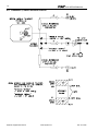
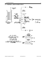
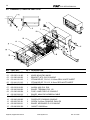
1
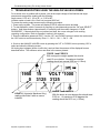
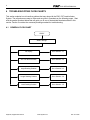
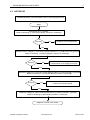
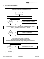
EI65
SERVICE MANUAL
SkyAzúl, Equipment Solutions
6126
www.skyazul.com
301-371-
NOTICE
SkyAzúl makes no warranty of any kind with regard to this material, including, but not limited to, the
implied warranties of merchantability and/or its fitness for a particular purpose.
SkyAzúl will not be liable for errors contained in this manual or for incidental or consequential
damages in connection with the furnishing, performance, or use of this manual. This document
contains proprietary information, which is protected by copyright, and all rights are reserved.
No part of this document may be photocopied, reproduced, or translated to another language without
the prior written consent of SkyAzúl.
SkyAzúl reserves proprietary rights to all drawings, photos and the data contained therein. The
drawings, photos and data are confidential and cannot be used or reproduced without the written
consent of SkyAzúl. The drawings and/or photos are subject to technical modification without prior
notice.
All information in this document is subject to change without notice.
SkyAzúl, Inc.
200 W. Main Street, Suite, 2A
Middletown, MD 21769
Fax 301-371-0029
[email protected]
SkyAzúl, Equipment Solutions
www.skyazul.com
301-371-6126
SkyAzúl, Equipment Solutions
www.skyazul.com
301-371-6126
EI65 SERVICE MANUAL
Table of Contents
1
GENERAL INFORMATION............................................................................................. 1
REFERENCE:................................................................................................................................. 1
SYSTEM MALFUNCTION: ............................................................................................................. 1
SYSTEM DESCRIPTION:............................................................................................................... 1
2
WARNINGS .................................................................................................................... 2
3
TROUBLESHOOOTING USING THE ANALOG VALUES SCREEN ............................. 3
4
TROUBLESHOOTING FLOW CHARTS ........................................................................ 4
4.1
4.2
4.3
4.4
4.5
4.6
GENERAL FLOW CHART............................................................................................................4
NO DISPLAY ................................................................................................................................5
ANTI TWO BLOCK PROBLEM ....................................................................................................6
ANGLE READING PROBLEM......................................................................................................8
LENGTH READING PROBLEM ...................................................................................................9
LOAD READING PROBLEM ......................................................................................................11
5
ERROR CODE TABLE ................................................................................................. 13
6
SYSTEM DRAWINGS................................................................................................... 14
Connection Board 056-065-300-002 Designations:.................................................................. 14
6.1 DRAWING 1. SYSTEM WIRING DIAGRAM (REFER TO INSTALLLATION
MANUAL 031-300-190-008) .......................................................................................................14
6.2 DRAWING 2. CONNECTION BOARD LAYOUT ........................................................................15
6.3 DRAWING 3. MAIN BOARD LAYOUT .......................................................................................15
6.4 DRAWING 4, ANGLE SENSOR CIRCUIT ..................................................................................16
6.5 DRAWING 5, LENGTH SENSOR CIRCUIT ................................................................................17
6.6 DRAWING 6, LINERIDER CIRCUIT ...........................................................................................18
6.7 DRAWING 7, LINERIDER SUPPLY VOLTAGES .......................................................................19
6.8 DRAWING 8, CONSOLE PARTS LIST.......................................................................................20
SkyAzúl, Equipment Solutions
www.skyazul.com
301-371-6126
GENERAL INFORMATION
1
1 GENERAL INFORMATION
The purpose of this service manual is to provide additional information to assist a service or
maintenance person in identifying malfunctions or system problems with the PAT System. A digital
voltmeter and regular maintenance and service tools will be required to troubleshoot the system. Note:
Knowledge of how to use a digital voltmeter is assumed.
REFERENCE:
Operator’s Manual 056-065-190-005
Calibration Manual 031-300-190-009
Installation Manual 031-300-190-008
SYSTEM MALFUNCTION:
In case of a malfunction of the system, an error code which identifies the
system malfunction will be displayed in the reeving portion of the display.
The error codes are listed in Section 4, Error Codes. The table identifies
various faults that can occur with the EI65, explain each fault, and describe the action, which shall be
taken to correct the fault.
MB 115.0 J1 85.0 J2 50.0 0J 15.0 E71
Faults within the electronic microprocessor shall be repaired by factory trained service personnel.
When these faults occur, contact your authorized dealer or service organization.
If the operator identifies a possible problem in the system, perform the pre-operation inspection
Section 5 in the Operator’s Manual 056-065-190-005 to define the problem.
SYSTEM DESCRIPTION:
The PAT Length-Angle-Radius-Load Indicator System EI65 has been designed to provide the crane
operator with the essential information required to enable the machine to be used within its design
parameters. The EI65 System indicates the length and angle of the boom, tip height, working radius
and the total weight being lifted by the crane. Using the various sensors and the limits set by the
operator, the EI65 System warns the crane operator of certain approaching hazardous conditions
which could occur during the operation of his crane.
WARNING
Always refer to operational instructions and load charts provided by the crane
manufacturer for specific crane operation and load limits.
SkyAzúl, Equipment Solutions
www.skyazul.com
301-371-6126
2
EI65 SERVICEMANUAL
2 WARNINGS
•
The EI65 is an operational aid, which warns a crane operator of certain approaching hazardous
conditions, which could cause damage to equipment and personnel.
•
The device is not, and shall not be, a substitute for good operator judgment, experience and use of
accepted safe crane operating procedures.
•
The responsibility for the safe operation of the crane shall remain with the crane operator who shall
ensure that all warnings and instructions supplied are fully understood and observed.
•
Prior to operating the crane, the operator must carefully and thoroughly read and understand the
information in the operator’s manual to ensure that he/she knows the operation and limitations of
the indicating system and crane.
SkyAzúl, Equipment Solutions
www.skyazul.com
301-371-6126
Troubleshoooting Using The Analog Values Screen
3
3 TROUBLESHOOOTING USING THE ANALOG VALUES SCREEN
For a sensor error or problem with a sensor, look at the output voltage of the linerider and angle
sensors and compare the reading with the following:
Angle sensor 1.875 at 0°, 2.5 at 45°, or 3.125 at 90°
Linerider under no load is 0 to 15mV not to exceed 2500 mV.
To access the analog output screen use the following procedure.
1. Power up the system. The screen will display EI 65/10 software version and date.
2. To start calibration, within 5 seconds of powering up, simultaneously press the “OK” and “SELECT”
buttons. Hold these buttons (approximately 15 seconds) until the screen changes to “CALIB.
PASSWORD”. If these buttons are not pressed and held, the screen changes to the existing
operating configuration. Refer to Operator’s section in this manual.
3. Enter the calibration password “0815”. Use the “UP” and “DOWN” buttons to select the number and
the “OK” button to confirm each entry. Enter 0 – OK, 8 – OK, 1 – OK, 5 - OK
4. Scrole to the ANALOG VALUES screen by pressing the “UP” or “DOWN” arrows, pressing “OK” to
select and show the following screen.
All Analog input voltages (shown in millivolts), received from the sensors will be displayed here as
described below. The minimum values are show in the screen pictured.
FORCE 1 and FORCE 2
With no signal or weight applied this should
read 15 mv or below. At maximum load the
reading should not exceed 2500 mv (+/-25mv).
1950
0
15
VOLT *1000
3125 3125
LENGTH (Hydraulic Machines Only)
reading should be 0 with no sensor
installed.
SkyAzúl, Equipment Solutions
ANGLE 1 and ANGLE 2
With the boom at zero degrees this should read
3125 mv . At maximum or 90 degrees the
reading should be 1875 mv (+/-25mv).
www.skyazul.com
301-371-6126
4
EI65 SERVICEMANUAL
4 TROUBLESHOOTING FLOW CHARTS
This section explains how to handle a problem that may arise with the EI65, PAT Load Indicator
System. The procedures are easy to follow and are given in flowcharts on the following pages. Start
with the general flowchart below that will guide you to one of the detailed flowcharts shown in this
section. Section 5 contains the necessary drawings needed for troubleshooting.
4.1
GENERAL FLOW CHART
START
What’s Wrong?
No display
Go to Section 3.1
Anti-Two Block Problem
Go to Section 3.2
Angle Reading Problem
Go to Section 3.3
Length Reading Problem
Go to Section 3.4
Load Reading Problem
Go to Section 3.5
SkyAzúl, Equipment Solutions
www.skyazul.com
301-371-6126
TROUBLESHOOTING FLOW CHARTS
4.2
5
NO DISPLAY
PROBLEM: Blank console display with no warning light shown.
Start
Check fuse F1 in console.
Refer to Drawing 2, Connection Board, Section 5. Drawings.
Correct?
No
Replace fuse (2amp/250V)
Yes
Measure crane voltage on connection board between X1:1 (+UB) and X1:3 (ground).
Refer to Drawing 1, System Diagram, Section 5. Drawings.
Correct?
No
Check crane power supply for faulty
crane electric or if supply is too low.
Yes
Measure voltage on connection board between MP4 (+5.25V) and MP1 (ground).
Refer to Drawing 2, Connection Board, Section 5. Drawings.
Correct?
No
Defect on connection board. Replace
console connection board.
Yes
Measure voltage to main board between MP15 (+5.25V) and MP1 (ground).
Refer to Drawing 3, Main Board, Section 5. Drawings..
Replace console main board.
SkyAzúl, Equipment Solutions
www.skyazul.com
301-371-6126
6
4.3
EI65 SERVICEMANUAL
ANTI TWO BLOCK PROBLEM
PROBLEM: Function of Anti-Two-Block System is faulty.
START
Check to see whether or not crane is in two-block condition.
Correct?
No
Lower hook down into safe position
Yes
Check weight position. Refer to Operator's Section of Handbook 056-065-190-005
Section 5. Pre-Operation Inspection, item 1, 2, and 3 for
switch weight positions for the main boom and extension.
Correct?
No
Position the weight properly.
Yes
Check the A2B circuit at the boom tip junction box.
With power off, measure A2B signal boom tip junction box.
With the bypass plugs and switch weight in position the ohm meter reads 4.7K ohms.
Refer to Installation Manual for system wiring diagram.
Correct?
No
Replace Anti-Two-Block switch.
Yes
Next Page
SkyAzúl, Equipment Solutions
www.skyazul.com
301-371-6126
ANTI-TWO BLOCK PROBLEM
7
PREVIOUS PAGE
With power off, measure the A2B signal in the console at the X1:9 and X1:10.
With the switch weight in position the ohm meter reads 4.7K ohms.
Refer to Installation Manual for system wiring diagrams.
Correct?
Fault in cable assembly. Check cable assemblies
and replace defective cable.
Refer to Installation Manual for system wiring diagrams.
No
Yes
With power on and the switch weight in position,
If the Anti-Two Block condition exists replace connection board.
A2B relay defective on connection board.
Refer to Drawing 2 in Section 5.
Yes
End
SkyAzúl, Equipment Solutions
www.skyazul.com
301-371-6126
8
4.4
EI65 SERVICEMANUAL
ANGLE READING PROBLEM
PROBLEM: Displayed Angle Incorrect. Actual measured angle is different from displayed angle.
START
Use a calibrated inclinometer to measure the actual main boom angle
and compare with displayed angle on console.
Refer to Installation Manual, Section 5 Mechanical Adjustments of Cable Reel Sensors.
Check the supply voltage to angle sensor on connection board
between X1:17 (+5VDC) and X1:20 (ground).
Refer to Installation Manual for system wiring diagram.
Correct?
Check system power supply voltage.
Refer to Section 3.2 No Display, this manual.
No
Yes
Check the voltage at angle sensor between connector pins A (AGND) and C (+5V).
Refer to Installation Manual for system wiring diagrams.
Correct?
Cable defective, replace cable or cable assembly.
Refer to Installation Manual for system wiring diagrams.
No
Yes
Check the voltage between X1:20 (ground) and X1:18 (signal/output voltage).
Voltage should be 3.125V (0°), 2.5V(45°), 1.875V (90°).
Refer to Drawing 4, Angle Sensor Circuit in Section 5.
Correct?
Yes
No
Replace Angle Sensor.
Refer to Installation Manual, Section 5 Mechanical Adjustments of
Cable Reel Sensors.
Complete steps 4.1, 4.2, 4.3, 4.8, 4.8.1 and 4.14 through 4.16 in the Calibration Manual,
031-300-190-009. Do NOT select Default in of section 4.4 or all other calibration data
will be lost, and you will have to complete the entire calibration procedure.
END
SkyAzúl, Equipment Solutions
www.skyazul.com
301-371-6126
LOAD READING PROBLEM
4.5
9
LENGTH READING PROBLEM
PROBLEM: Length reading incorrect. Crane is not in “out of load chart” condition.
START
Check mechanical adjustment of length potentiometer in cable reel.
Refer to Installation Manual, Section 5 Mechanical Adjustments of Cable Reel Sensors.
Correct?
No
If unable to adjust, replace length potentiometer assembly. Remove slip ring body
from shaft and remove gear wheel from potentiometer axle. Unscrew mounting
plate and remove potentiometer assembly from mounting plate. Remove
assembly wires form terminal block. Connect new assembly to terminal block.
Reinstall mounting plate, gear wheel and slip rings. With boom fully retracted,
reset potentiometer by turning counter-clockwise until it stops.
Refer to Installation Manual for system wiring diagrams and Section 5 Mechanical
Adjustments of Cable Reel Sensors.
Yes
Check out clutch in big gear wheel of length transducer. Extend and retract
boom to ensure that clutch is not sipping on potentiometer axle.
Correct?
No
Replace the gear wheel, clean potentiometer
axle. Reset length potentiometer.
Refer to Installation Manual, Section 5 Mechanical Adjustments
of Cable Reel Sensors.
Yes
Check 5.0V power supply to length transducer on connection board.
Refer to Installation Manual for system wiring diagram or connection board
designations this manual.
Correct?
No
Check system power supply voltage.
Refer to Section 3.2 No Display, this manual.
Yes
NEXT PAGE
SkyAzúl, Equipment Solutions
www.skyazul.com
301-371-6126
10
EI65 SERVICEMANUAL
PREVIOUS PAGE
Measure supply to length transducer in cable reel, between Pin 1 (ground) and Pin 3 (-5v)
Refer to Installation Manual for system wiring diagram
Correct?
Cable defective, replace cable or cable assembly.
Refer to Installation Manual for system wiring diagrams.
No
Yes
Measure signal from length transducer in cable reel at terminal between pin 2(signal) and pin
1(ground). Retract boom - 0 Potentiometer turn = -0.5v 10 Potentiometer turn = -4.5v
Refer to Drawing 5 Length Sensor Circuit.
Correct?
No
Replace length potentiometer assembly. Remove slipring body from shaft and
remove gear wheel from potentiometer axle. Unscrew mounting plate and
remove potentiometer assembly from mounting plate. Remove assembly
wires form terminal block. Connect new assembly to terminal block. Reinstall
mounting plate, gear wheel and slip rings. With boom fully retracted, reset
potentiometer by turning counter-clockwise until it stops.
Yes
Measure signal from length transducer at console connection board between X1-20 (ground) and X119 (signal: -0.5 and -4.5v) Refer to Installation Manual for system wiring diagram or connection board
designations this manual.
Correct?
No
Cable defective, replace cable or cable assembly.
Refer to Installation Manual for system wiring diagrams.
Yes
Measure length signal on main board between test point MP4 (signal) andMP1 (ground).
NOTE: Negative signal at terminal X1 Pin 15 will be converted into positive signal at MP6
(i.e.: input at terminal X1 Pin 15 = -0.5V; output test between MP15 and MP6 = +0.5v).
Refer to Drawing 3, Main Board, Section 5.
Main board defective.
END
SkyAzúl, Equipment Solutions
www.skyazul.com
301-371-6126
LOAD READING PROBLEM
4.6
11
LOAD READING PROBLEM
PROBLEM: Displayed Load is out of tolerance. The displayed load
should be equal to or 10% greater than the actual load.
START
Complete Pre-Operation Inspection in Section 5 of the Operator's Manual 056-065-190-005.
Before changing calibration information complete the following steps.
Check the Main/Aux voltages on connection board between
X1:25 (+9V) and X1:8 (ground)
X1:28 (-9V) and X1:8 (ground)
Refer to Installation Manual for system wiring diagram or connection board designations this
manual.
Correct?
Check system power supply voltage.
Complete to Section 3.2 No Display.
No
Yes
Check the voltage at linerider between connector pins A (+9V) and B (-9V).
Voltage = 18V
Refer to Drawing 7 in Section 5 and the Installation Manual for system wiring diagram.
Correct?
No
Cable defective, replace cable or cable assembly.
Refer to Installation Manual for system wiring diagrams.
Next Page
SkyAzúl, Equipment Solutions
www.skyazul.com
301-371-6126
12
EI65 SERVICEMANUAL
Previous Page
Remove hoist rope so there is no load on the load cell of the linerider.
Check the zero point of the Linerider on connection board between
Main X1:26 (+sig) and X1:27 (-sig)
Aux X1:30 (+sig) and X1:31 (-sig)
Voltage = 0 ±0.025V
Refer to Drawing 6 Linerider Circuit in Section 5 and the Installation Manual for system
wiring diagrams.
Correct?
No
With no load on the load cell of the linerider.
Check the zero point of the linerider in the boom tip junction box or as
close to the linerider as possible. Check the Main '+' and '-' signal and/or
the Check the Aux '+' and '-' signal at Voltage = 0 ±0.025V
Refer to Drawing 6 Linerider Circuit in Section 5 and the Installation
Manual for system wiring diagrams.
No
Check cable continuity; Replace cable if necessary
No
Replace Load Cell or Linerider Assembly
Yes
Lift test load and verify linerider output voltage increases after lifting the test load.
Main X1:26 (+sig) and X1:27 (-sig)
Aux X1:30 (+sig) and X1:31 (-sig)
Refer to Drawing 6 Linerider Circuit in Section 5 and the Installation Manual for system wiring diagrams.
No
Complete steps 4.1, 4.2, 4.3, 4.11 (Main) or 4.12 (Aux) through 4.16 in the Calibration Manual, 031300-190-009. Do NOT select Default in of section 4.4 or all other calibration data will be lost,
and you will have to complete the entire calibration procedure.
No
Replace Load Cell or Linerider Assembly
End
SkyAzúl, Equipment Solutions
www.skyazul.com
301-371-6126
SYSTEM DRAWINGS
13
5 ERROR CODE TABLE
Error code
11
Reason
Operating data in the buffered RAM
21
Action
Turn on the system again and
adjust operating data
Re-calibrate the system
Crane parameters in the serial EPROM
incorrect
31
Wrong EPROM programming or EPROM
Exchange EPROM
defective
51
Short circuit min layer device term 11&12
Check minimum layer device
52
Cable break min layer device term 11&12
Check minimum layer device
53
Short circuit A2B -switch - 2 term 13&14
Check anti-two block system
54
Cable break A2B -switch - 2 term 13&14
Check anti-two block system
55
Short circuit A2B -switch - 1 term 9&10
Check anti-two block system
56
Cable break A2B -switch - 1 term 9&10
Check anti-two block system
Load
on
the
main
hoist
hook
too
big
Reduce
load on main hoist
•61
Load on the auxiliary hoist hook too big
Reduce load on aux. hoist
•63
Limit
Length
Main
Boom
Max.
Decrease length limit
•71
Limit Length - Main - Boom - Min.
Increase length limit
•72
Limit WG - Main - Boom - Max.
Decrease main boom angle
•73
Limit WG - Main - Boom - Min.
Increase main boom angle
•74
Limit Boom height - Max.
Decrease main boom angle
•75
Limit Boom height - Min.
Increase main boom angle
•76
Limit Working radius - Max.
Increase main boom angle
•77
Limit
Working
radius
Min.
Decrease
main boom angle
•78
81
ADC-Measuring value KMD1 too big
Check zero point in linerider
82
ADC-Measuring value KMD1 too low
Check zero point in linerider
83
ADC-Measuring value KMD2 too big
Check zero point in linerider
84
ADC-Measuring value KMD2 too low
Check zero point in linerider
91
ADC-Measuring value LG1 too big
Check main length sensor circuit
92
ADC-Measuring value LG1 too low
Check main length sensor circuit
93
ADC-Measuring value WG1 too big
Check main angle sensor circuit
94
ADC-Measuring value WG1 too low
Check main angle sensor circuit
95
ADC-Measuring value WG2 too big
Check luffing angle sensor circuit
96
ADC-Measuring value WG2 too low
Check luffing angle sensor circuit
• Limit set by the operator refer to Operator’s Manual, Section 4.3. Activating and Setting Preset
Limits
SkyAzúl, Equipment Solutions
www.skyazul.com
301-371-6126
14
EI65 SERVICEMANUAL
6 SYSTEM DRAWINGS
The PAT EI65 System drawings in this section are provided as reference material for the
troubleshooting flow charts. Use the drawings in conjunction with the flow charts to help understand
the operation of the EI65 system.
Drawing List:
1. System Diagram
2. Connection Board Layout
3. Main Board Layout
4. Anti-Two Block Circuit
5. Angle Sensor Adjustment
6. Angle Sensor Circuit
7. Linerider Circuit
Refer to the Operator’s Manual for basic component layout on the crane and console drawing. The
EI65 console connection board has the following terminal designations.
Connection Board 056-065-300-002 Designations:
1
2
3
4
5
6
7
8
9
10
11
12
13
14
15
16
6.1
+ Battery
+ Battery
- Battery
- Battery
Load Limit output
A2B Relay output 2
A2B Relay output 1
Peripheral ground
A2B 1 input
A2B Ground
A2B 2 input
A2B Ground
3rd Wrap Switch input
3rd Wrap Switch ground
Digital input 1
Digital input 2
17
18
19
20
21
22
23
24
25
26
27
28
29
30
31
32
+5VDC
Main Boom angle input
Main Boom Length input
Analog Ground
+5VDC
Jib Angle input
Analog Ground
Analog Ground
+9VDC
KMD1 +Signal input
KMD1 -Signal input
-9VDC
+9VDC
KMD2 +Signal input
KMD2 -Signal input
-9VDC
DRAWING 1. SYSTEM WIRING DIAGRAM (REFER TO INSTALLLATION MANUAL
031-300-190-008)
SkyAzúl, Equipment Solutions
www.skyazul.com
301-371-6126
SYSTEM DRAWINGS
6.2
15
DRAWING 2. CONNECTION BOARD LAYOUT
MP1 = GND
MP2 = 5.6V
MP3 = 5.6V
MP4 = .5V min sig.
To 4.5V max sig.
6.3
DRAWING 3.
MAIN BOARD LAYOUT
MP0 = GND
MP1 = AGND
MP2 = +5.0V
MP3 = +5.0V
MP4 = SIGNAL, LENGTH CHANNEL
MP5 = SIGNAL, ANGLE 2
MP6 = SIGNAL, ANGLE 1
MP7 = SIGNAL, KMD1
SkyAzúl, Equipment Solutions
MP8 = SIGNAL, KMD2
MP9 = AN5 REFERENCE VOLATGE
MP10 = AN6 REFERENCE VOLTAGE
MP11 = AN7 REFERENCE VOLTAGE
MP12 = -0.5V
MP13 = +5.0V
MP15 = 5.25V
www.skyazul.com
301-371-6126
16
6.4
EI65 SERVICEMANUAL
DRAWING 4, ANGLE SENSOR CIRCUIT
SkyAzúl, Equipment Solutions
www.skyazul.com
301-371-6126
SYSTEM DRAWINGS
6.5
17
DRAWING 5, LENGTH SENSOR CIRCUIT
SkyAzúl, Equipment Solutions
www.skyazul.com
301-371-6126
18
6.6
EI65 SERVICEMANUAL
DRAWING 6, LINERIDER CIRCUIT
SkyAzúl, Equipment Solutions
www.skyazul.com
301-371-6126
SYSTEM DRAWINGS
6.7
19
DRAWING 7, LINERIDER SUPPLY VOLTAGES
The supply voltage can be checked directly at the cannon connection. Using a digital voltmeter
measure between pins A and B, (A= +9v) + (B= -9v) = 18volts. If this voltage is not correct refer to
the system wiring diagram and verify all cable connections. You may need to start at the console and
check the supply voltages at their proper measuring points.
SkyAzúl, Equipment Solutions
www.skyazul.com
301-371-6126
20
6.8
EI65 SERVICEMANUAL
DRAWING 8, CONSOLE PARTS LIST
NO. PART NO.
QTY DESCRIPTION
01
02
03
04
05
050-000-100-075
050-350-110-183
031-300-100-293
021-441-161-213
021-441-131-013
1
2
1
1
1
HOUSING, CONSOLE, EI65
KNOB, MOUNTING KNOB
BRACKET, MTG. EI65 CONSOLE
STRAIN RELIEF, PG13.5, 12-15mm GRAY+WHITE INSERT
STRAIN RELIEF, PG 13.5, 8-12mm RED+WHITE INSERT
06
07
08
09
10
000-214-210-013
000-323-010-525
056-065-300-002
031-300-100-294
056-065-300-010
2
1
1
2
1
NUT, PG13.5
ALARM, A2B, EI10, EI20
BOARD, TERMINAL EI65, 12V
FUSE, 4 AMP FOR EI-65 CONSOLE
BOARD, MAIN EI65 W/RIBBON CABLE
11
12
13
14
15
050-000-100-078
056-065-100-005
002-053-703-101
056-065-300-011
050-000-050-309
1
1
6
1
1
DISPLAY
FACEPLATE, EI65/0005 CONSOLE
SCREW, 3x10mm, PANHEAD, PHILLIPS
BOARD, KEYBOARD, EI 65 CONSOLE
GASKET 108X256mm
SkyAzúl, Equipment Solutions
www.skyazul.com
301-371-6126
SkyAzúl, Inc.
www.skyazul.com
SkyAzúl, Equipment Solutions
www.skyazul.com
200 W. Main Street, Suite, 2A
Middletown, MD 21769
Phone 301-371-6126
Fax 301-371-0029
[email protected]
301-371-6126